

Page 1
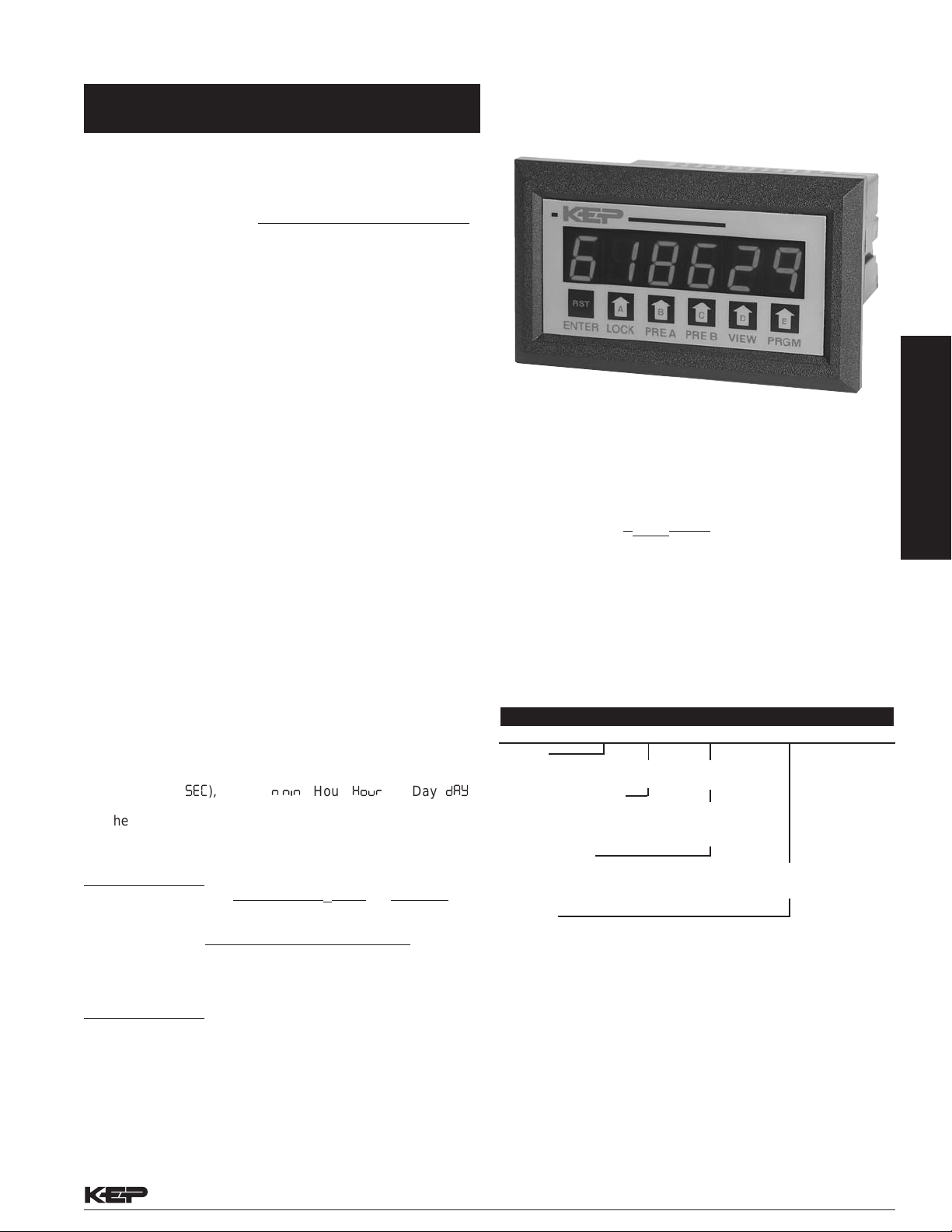
MINITROL-PW
Features
• Display Rate & Total
Flowrate Display =
• 30mV Magnetic Pickup Inputs (optional)
• RS422/RS232 Serial Communication (optional)
Input Frequency + Offset B
Factor A
Totalizer/Ratemeter for Paddle or
Pelton Wheel Turbine Flowmeters
• NEMA 4X / IP65 Front Panel
• 4-20mA or 0-20mA Analog Output (optional)
DESCRIPTION:
The Minitrol-PW is a single input counter/ratemeter intended for use
with low flow paddle or pelton wheel turbine flowmeters. Two scale
factors are used to describe the flowmeter calibration characteristics.
The two 5 AMP preset relay outputs can be programmed by the user
to apply to the "A" total counter or the "A" ratemeter. The user can
view the rate, total and grand total.
SPECIFICATIONS:
Electrical Specifications: See MINItrol-S
Dimensions: See MINItrol-S
K FACTOR/SCALING
The K-Factor is used to convert the input pulses to engineering
units. The two 5 digit scale factors, with decimal keyed into any
position, allow easy direct entry of any scaling factor from 0.0001
to 99999. Factor A is used to enter the linearized K-Factor and
Factor B is used to enter the offset frequency.
LOW FLOW CUTOFF:
A low flow cutoff is provided to inhibit operation in low flow out of
range regions.
RATEMETER
Accurate to 4 1/2 digits (±1 display digit). The rate meter can
be programmed to accept almost any number of pulses per
unit of measurement and auto-range up to 5 digits of significant
information. The display can be programmed to read in units
per Second (
COUNTER
The two 6-digit totalizers can count at 10kHz speed. They
share a 5-digit dividing scale factor. The totalizer performs as
follows:
If Freq. In > Cutoff
Total increment =
Rate = (Freqin + Freq offset) • time base
Time base: Sec =1, Min = 60, Hour = 3600, Day = 86400
If Freq. In < Cutoff
Total Increment = 0
Rate = 0
Total B (grand total) increments with Total A.
sec
), Minute (
min
), Hour (
Freq. Offset • ∆ Time + Pulses In
K Factor A K Factor A
K Factor A
hour
), or Day (
day
THEORY OF OPERATION
Low flow, Pelton Wheel turbine flowmeters have a transfer
characteristic which can best be represented by the following
equation for frequencies above the minimum usable flowrate
for the device:
frequency =
Where: K
determined during flow sensor calibration.
This transfer characteristic applies within the meter
manufacturers published range. Below some minimum flow
meter output frequency, the flow rate should be considered
as 0 and the totalization inhibited. This is called the "cutoff"
frequency.
K
• GPM – Offset Frequency
linearized
( )
linearized
60
and offset frequency are scaling constants
Ordering Information
Example: MRTPW A 3 1
Series:
MRTPW=6 digit counter / 5 digit ratemeter
).
Operating Voltage:
A= 110 VAC ± 15% or 12 to 15 VDC
B= 220 VAC ± 15% or 12 to 15 VDC
C= 24 VAC ± 15% or 12 to 15 VDC
Count Inputs:
3 = Standard, 4-30 VDC simultaneous inputs.
3M = Mag. Input, rate/total input only, 30mV input
Options
1= RS232 Communications
2= RS422 Communications
A= Analog Output (4-20/0-20 mA)
NOTE: RS232/RS422 & Analog Output options can not be combined
Accessories
Separate non keyboard panel order #34235
Separate keyboard panel - order #34234
NEMA4 wall mount enclosure available, see NEMAtrol
Explosion proof enclosure available, see XHV
Serial printer available, see P1000, P295
Ethernet Port Server available, see IEPS
RS-422/485 to RS-232 Communication Adaptor available, see CA285
with presets and scaling.
(Inhibit input, 4-30V)
RATEMETERS/TOTALIZERS
Flow Instruments
Kessler-Ellis Products • 800-631-2165 F-15 • Flow Instruments • Page 51
Page 2
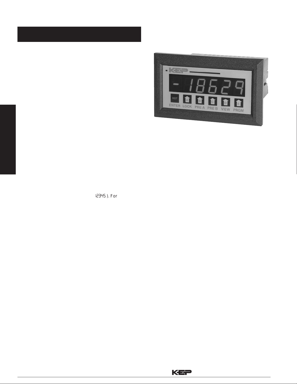
DRT(Dual rate/totalizer)
Features
• Displays A,B,&C Rate & A,B,&C Total
• Separate Scaling Factors For A & B Inputs
• “C” Displays A+B, A-B, A÷B, & A÷A+B
• RS422/RS232 Serial Communication
• Modbus RTU RS422/RS485/RS232
• Pulse Input - 10 kHz Max.
• Security Lockout
2 Separate Rate/Total Displays
with Combination Function
• NEMA 4X / IP65 Front Panel
• 30mV Magnetic Pickup Inputs
Flow Instruments
DESCRIPTION:
The DRT (Dual Rate Totalizer) is a dual 5 digit Ratemeter 6 digit
Totalizer in a 1/8 DIN package. User selects 1 of 6 displays to
RATEMETERS/TOTALIZERS
show A, B or C rate and A, B or C total. Inputs A and B have
separate scaling to read in engineering units.
A 4-20mA (0-20mA) output of the C rate or total is optional.
The user can press the VIEW button to see 6 separate items
total A, total B, total C, rate A, rate B, rate C. Negative values
are displayed with a negative symbol ( the user can choose from the following combination of A&B
inputs: TOTAL; with a choice of A+B or A-B; RATIO with choice
of A÷B(x100) to show percent of A to B quantity or A÷[A+B(x100)]
to show percent of A to total quantity.
Two independent presets are standard. User selects whether
output A is activated by total or rate value of input A or selected
C. Output B can be activated by total or rate value of input B or
selected C. Outputs activated by A or B total can be set to latch
or autorecycle with an adjustable output duration from 00.1 to
99.9 sec. For rate, ratio, or C total outputs pull in when value is
equal or above the preset and drop out when value is below the
preset minus the selected 0 to 999 hysteresis.
SPECIFICATIONS:
DISPLAY:
6 digit, 0.55" High LED
INPUT POWER:
110 VAC ± 15% or 12 to 15 VDC
220 VAC ± 15% or 12 to 15 VDC
24VAC ± 15% or 12 to 15 VDC
CURRENT:
250 mA DC max. or 6.5 VA
OUTPUT POWER: (AC powered units only)
+12 VDC @ 50 mA, unregulated -10 + 50%
TEMPERATURE:
Operating: +32°F (0°C) to +130 F (+54°C)
Storage: -40 F (-40°C) to +200°F (93°C)
HUMIDITY: 0-90% Noncondensing
(6.5W) AC
12345
). For the C value,
• 4-20mA or 0-20mA Analog Output
• CSA Listed
MEMORY:
EEPROM stores data for 10 years if power is lost.
INPUTS:
3: High Impedance DC pulse input 4-30 VDC (high), Open or
0-1 VDC (low), 10 KΩ imp. 10 kHz max. speed. Accepts
simultaneous inputs.
3M: Mag. Input, Input A only, accepts 30mV input (50 V max. P/
P) signals 10 KΩ imp. 5 kHz max. (Input B, 4-30V)
3MB: Mag. Input, Inputs A & B, accepts 30mV input (50 V max.
P/P) signals 10 KΩ imp. 5 kHz max.
RESET:
Front Panel: Resets displayed value and control output
Remote: 4-30 VDC negative edge resets all counters,
"A" counter or "B" counter (user selectable).
K FACTOR/SCALING
The DRT has two separate K-Factors that are used to convert
the input pulses to engineering units. The 5 digit K-Factor
dividers, with decimal keyed into any position, allow easy direct
entry of any K-Factor from 0.0001 to 99999. Separate factors
may be entered for the 2 separate input channels.
CONTROL OUTPUTS:
Relays:
2 each N.O. Relay; 5 Amps 120/240 VAC or 28 VDC.
(N.C. relay contacts and NPN transistor output
available with solder jumpers. Transistor output is
internally pulled up to 10 VDC through relay coil, sinks
from 10 VDC to .5 V @ 100 mA)
Analog Output:
An optional 4-20mA (0-20mA) output is available for
the DRT. The output can be programmed
to track rate or total of the C display. This feature is available
by adding suffix A to the part number. Connections are
via a 2 terminal pluggable screw connector.
Programming is accomplished by using the front panel
in conjunction with rear dip switches.
Accuracy: 50uA worst case.
Compliance Voltage: 3 to 30 VDC non inductive.
Approvals: CSA File# LR91109-7, CE Compliant
Page 52 • Flow Instruments • F-15 Kessler-Ellis Products • 800-631-2165
 Loading...