

KEP INTELLECT-69 Series, INT-69RT, INT-69T, INT-69R Installation & Operating Instructions Manual
Page 1

INTELLECT-69
INSTALLATION & OPERATING INSTRUCTIONS
MODELS
INT-69RT
INT-69R
INT-69T
(with RS232 &
RS422 Option)
V ersion V_41
KESSLER-ELLIS PRODUCTS CO.
10 Industrial Way East
Eatontown, NJ 07724
http://www.kep.com
99318 10/2/98
Telephone: (732) 935-1320
T oll Free: (800) 631-2165
Fax: (732) 935-9344
Page 2

Proprietary Notice
The information contained in this publication is derived in part from proprietary and patent data.
This information has been prepared for the expressed purpose of assisting operating and
maintenance personnel in the efficient use of the instrument described herein. Publication of
this information does not convey any rights to use or reproduce it or to use for any purpose other
than in connection with the installation, operation and maintenance of the equipment described
herein.
Copyright 1990
Printed in USA. All Rights Reserved.
!
WARNING!
This instrument contains electronic components that are susceptible to damage by static
electricity. Proper handling* procedures must be observed during the removal, installation, or
handling of internal circuit boards or devices.
*Handling Procedure
1. Power to unit must be removed.
2. Personnel must be grounded, via wrist strap or other safe, suitable means, before any
printed circuit board or other internal device is installed, removed or adjusted.
3. Printed circuit boards must be transported in a conductive bag or other conductive container.
Boards must not be removed from protective enclosure until the immediate time of installation.
Removed boards must be placed immediately in protective container for transport, storage, or
return to factory.
Comments
This instrument is not unique in its content of ESD (electrostatic discharge) sensitive
components. Most modern electronic designs contain components that utilize metal oxide
technology (NMOS, CMOS, etc.). Experience has proven that even small amounts of static
electricity can damage or destroy these devices. Damaged components, even though they
appear to function properly, may exhibit early failure.
Page 3

TABLE OF CONTENTS
SAFETY INSTRUCTIONS ...........................................................1
DESCRIPTION & SPECIFICATIONS ..........................................2
MOUNTING .................................................................................3
WIRING........................................................................................4
TYPICAL WIRING HOOKUPS.....................................................5
OPEN COLLECTOR & RELAY OPERATION .............................5
PROGRAMMING FLOWCHART .................................................6
DEFINITIONS .............................................................................. 7
FRONT PANEL OPERATIONS ...................................................10
PROGRAMMING .........................................................................10
SETTING PRESETS & PANEL LOCK.........................................15
RS 232/422 OPERATIONS .........................................................16
RS 232/422 WIRING....................................................................20
TROUBLESHOOTING GUIDE ....................................................21
WARRANTY ................................................................................22
DECODING PART NUMBER ......................................................22
Page 4

THIS PAGE IS BLANK
Page 5

SAFETY INSTRUCTIONS
!
The following instructions must be observed.
• This instrument was designed and is checked in accordance with regulations in force
EN 60950 (“Safety of information technology equipment, including electrical business
equipment”).
A hazardous situation may occur if this instrument is not used for its intended purpose
or is used incorrectly. Please note operating instructions provided in this manual.
• The instrument must be installed, operated and maintained by personnel who have
been properly trained. Personnel must read and understand this manual prior to
installation and operation of the instrument.
• The us of an external line fuse is recommended. Add or replace the external fuse with
the following specified type and rating only:
Input Power Recommended Fuse
115 VAC 100 mA slow blow fuse
230 V AC 50 mA slow blow fuse
12-24 VDC 250 mA slow blow fuse
Disconnect power supply before adding or replacing fuse!
• The manufacturer assumes no liability for damage caused by incorrect use of the
instrument or for modifications or changes made to the instrument.
Symbols Used On Unit
Number Symbol Publication Description
1 IEC 417, No. 5031 Direct current
2 IEC 417, No. 5172 Equipment protected throughout by
DOUBLE INSULATION or REINFORCED
INSULATION (equivalent to Class II of IEC
536–see annex H)
3
!
ISO 3864, No. B.3.1 Caution (refer to accompanying documents)
Technical Improvements
• The manufacturer reserves the right to modify technical data without prior notice.
1
Page 6

DESCRIPTION & SPECIFICATIONS
Description:
Featuring 6 digits of bright, 7-segment LED displays,
this unit is an integrating totalizer/ratemeter which accepts analog signal inputs. The unit can be field
programmed to accept 0-20mA, 4-20mA, 0-5V, 010V or 1-5V signals. An optional Square Law input is
available for inputs that require square root extraction. A 4-20mA output option is available to control
strip recorders or other peripherals. Two assignable
set points are standard for two stage shut off. The
high and low scaling settings are programmable from
the front panel. By pressing the "view" button, the
unit will display: integrated total, rate, peak or valley.
RS-422 or RS-232 serial communications are available options for data communication with a host computer.
Specifications:
Display: 6 digit, .55" high, LED.
Input Power: 110, 220 VAC ± 15% or 12 to 24VDC.
Current: maximum 300 mA DC or 10.0 VA at rated
AC voltage.
Output Power: (AC powered units only) + 24VDC.
@ 50 mA regulated ±5%
Temperature:
Operating: +41°F (5°C) to +130°F (+54°C).
Storage: -40°F (-40°C) to +200°F (93°C).
Memory: EEPROM stores data for ten years if power
is lost.
Reset:
Front Panel: resets displayed values and control outputs.
Remote: 4-30 VDC positive edge, resets totalizer and
control outputs.
Control Outputs:
Standard: Open collector sinks 250 mA from 30VDC
when active.
Optional: 2 each Form C SPDT 10Amp @ 120/240
VAC or 28 VDC. (Open collector outputs are also
supplied with 10VDC provided at transistor outputs
through relay coil. If greater than 2mA is used, relay
will remain energized. Applying greater than 10 VDC
may destroy unit. Transistor will sink 100mA in "ON"
state.)
Input:
Standard: Linear 0-20mA, 4-20mA, 0-5V, 0-10V or 15V selectable from the front panel.
Optional: Square Law 0-20mA, 4-20mA, 0-5V, 0-10V,
or 1-5V, is available for inputs that require square root
extraction.
Input Impedance: Current: 100Ω; Voltage: 115KΩ
Calibration: The unit does all of the calibrations inter-
nally. There are no potentiometers to adjust and the unit
never needs to be removed from the case.
Set Points: The two control set points can be set at any
number from 0 to 59999. The set point outputs can be
assigned to rate or total. The unit comes standard with
two open collector control outputs. Two 5 Amp, Form C
relays are optional. The outputs are programmable
from .01 to 599.99 sec or latched until reset when
assigned to the total and a hysteresis (alarm range)
when assigned to the rate.
Rate Display: Updates 5 times per second, Accurate to
4.5 digits. Set "low" greater than "high" for inverted
display (LINEAR ONLY).
Totalizer: Integrates from the rate reading and accumulates up to 6 digits of total count. The time base
(hours, minutes or seconds) is field programmable from
the front panel.
Analog Out: The unit can be ordered with an optional
4-20mA output which is proportional to the rate display.
The high and low settings are programmable from the
front panel. Set "low" greater than "high" for inverted
output. A sinking driver generates a corresponding
linear current through the external devices. The output
updates with each update of the rate. Accuracy is 50uA
worst case. For rated accuracy, load must be connected to the analog output before unit is powered.
Compliance voltage must be 3 to 30 VDC non inductive.
(The unit can provide the DC source as long as the drop
across the devices being driven does not exceed 21V).
Programming: Decimal points, Scaling from 0 to
59999 units per selected time base, set points, input
type, security lock code, and assigning outputs are all
programmable from the front panel.
Housing: Standard 1/8 DIN, high impact 94VO plastic
case.
Shipping Weight: 2 lbs.
Overvoltage Protection:
50 V
Overcurrent Protection:
50 mA
Resolution: 14.5 Bits
Accuracy:
RANGE % FS ERROR % FS ERROR
(worst case) (typical)
4-20 mA 0.1% .05%
0-10 VDC 0.2% 0.1%
0-5 VDC .25% .15%
1-5 VDC .25% .15%
Square Law: (above 5% of bottom range) 0.1%
(5V inputs .4%) Worst case over complete range: 2%
Temperature Stability: Will not drift more than 20
parts per million per °C from 5°C to 54°C
2
Page 7
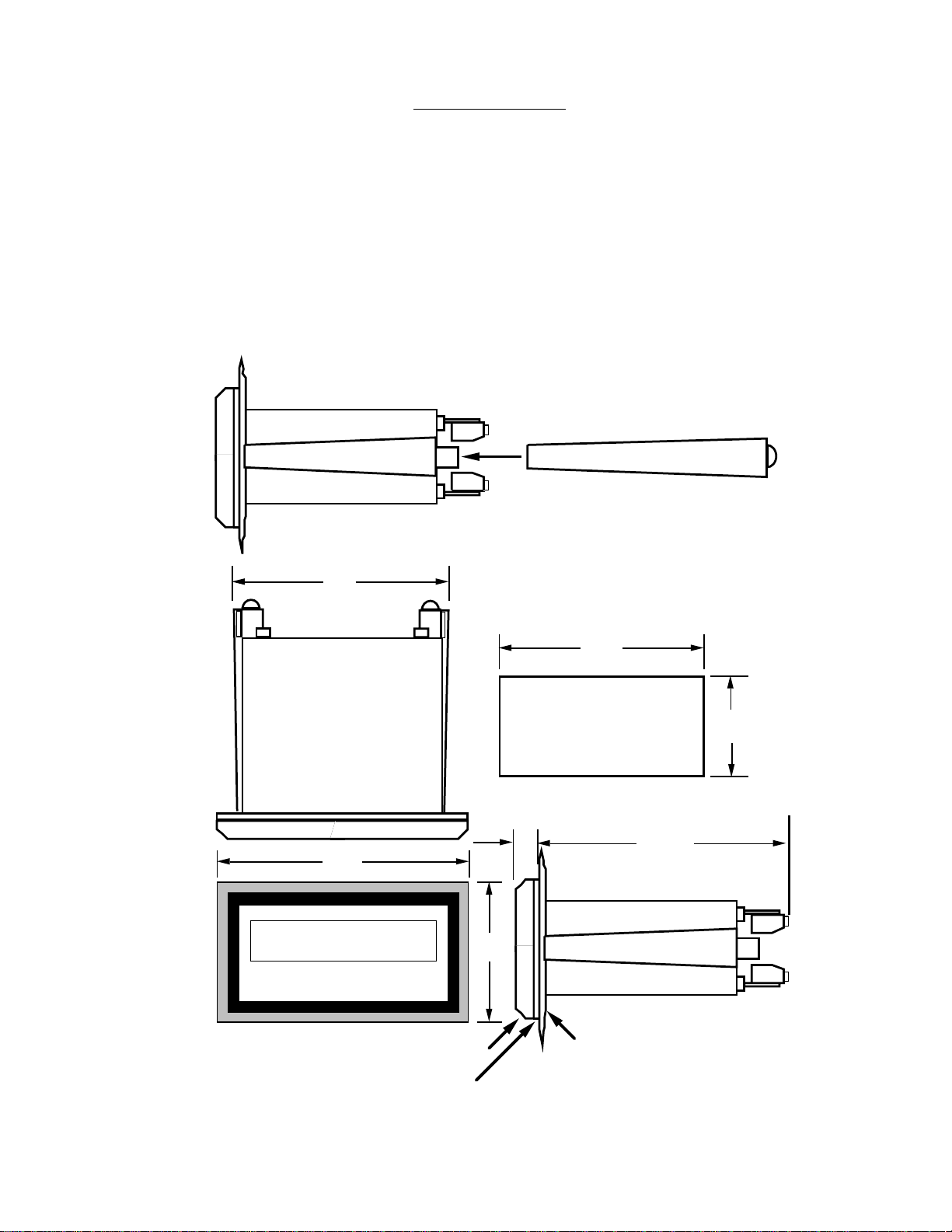
HOW TO MOUNT:
MOUNTING
Slide the body of the unit through the rubber
gasket. Insert the unit into the panel. Slide the
brackets up the groove to press against the
back of the panel, as shown in "FIG. A". Insert
the screws into the rear of the brackets.
FIG. A
3.925
(99.7)
Tighten the screws evenly and alternately. A
panel less than .1" may distort if the clamps are
screwed too tightly. Do not over tighten! A
normal level of torque is required. Maximum
torque should be 3" pounds.
The panel must be parallel to the bezel to
assure proper seal. Unit seals to NEMA 4/
IP65 if properly mounted.
4.437
(112.7)
BEZEL
GASKET
.587
2.625
(66.68)
3.622
(92)
1.772
(45)
4.245
(107.8)
CUSTOMER PANEL
Panel Thickness 0.062" (1.5)
to 0.187" (4.7) max.
3
Page 8
!
WIRING
AC / DC CONNECTIONS:
NOTE: Connect power only after other connections are finished. Do not touch the live AC power
terminals. The unit has been designed with an
isolated AC input, therefore polarity is not a concern for the AC power. The chassis is plastic,
therefore earth ground is not used. For DC operation, connect +DC to terminal 10 and -DC to
terminal 3.
This Product complies with requirements of the
European Community Directive 89/336/EEC [Electromagnetic Compatibility]. However, electrical
noise or intense electromagnetic fields in the vicinity of the unit may disturb the microprocessor.
Users should exercise care and should take proper
precautions to avoid microprocessor disturbance.
Four common sources of noise are:
1) AC power line noise- The input power lines
should not be common to power lines for motors,
pumps, contactors, etc. If the unit cannot be connected to an electrically clean power source, an
inductive load suppressing device (MOV as
GE#V130LA1 or Resistor Capacitor as Paktron#
.2uf/220 ohm @ 400V) can be installed. Although
locating the suppressor across the AC supply at
the unit should help, best results are obtained by
connecting the suppressor across the leads of the
"load" at the device causing the spikes.
2) Input line noise- The noise is carried on the input
and DC ground lines. Make sure the input wires
are not run into the unit in a bundle with power input
lines. We recommend using shielded cable. Connect the shield to DC ground of the unit and "earth"
at one point in the circuit preferably at the DC
ground terminal of the unit.
3) Output lines- The unit has two open collector
outputs and two optional relay outputs. When
these outputs are used to run external relays or
solenoids, spikes can be generated upon activation. This noise can spread through the instrument
causing operating problems. If the source is a D.C.
operated device, a general purpose diode (IN4004)
placed across the solenoid prevents electrical
noise spikes. Connect the cathode (banded side)
to the more positive side of the coil. If the source
is an A.C. operated device, use a Resistor Capacitor or MOV across the coil.
4) 24 VDC output supply- Noise can be generated
on the 24 VDC output supply if it is used to drive
inductive loads or if the current draw exceeds
50mA. Insure that all inductive loads have a diode
(such as IN4004) across the coil and that the
current does not exceed 50mA.
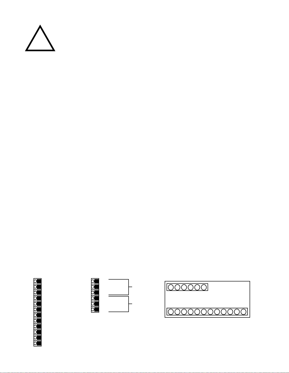
RESET IN
1
ANALOG OUT (SINK)
2
SIGNAL GND (-DC)
3
(CURRENT) +I IN
4
(VOLTAGE) +V IN
5
NOT USED
6
+24V OUT
7
PRESET B COLLECTOR
8
PRESET A COLLECTOR
9
+D.C. IN
10
110 / 220 VAC
11
110 / 220 VAC
12
WIRING CONNECTIONS
13
COMMON
14
N.C.
15
N.O.
16
COMMON
17
N.C.
18
N.O.
RELAY A
RELAY B
4
13 14 15 15 17 18
1 2 3 4 5 6 7 8 9 10 11 12
REAR VIEW
Page 9

TYPICAL WIRING HOOKUPS
3-Wire 0-10V Transmitter2-Wire 4-20mA Transmitter
Flowmeter
(4-20mA T ransmitter)
4-Wire 4-20mA Transmitter
Power
Supply
Flowmeter
(4-20mA T ransmitter)
2-Wire 4-20mA Transmitter
with Multiple Devices
-
+
Flowmeter
(4-20mA T ransmitter)
-
Strip Chart
Recorder
•7 - +24V Out.•11 - AC In
•12 - AC In
..•11 - AC In
•12 - AC In
•7 - +24V Out.•11 - AC In
•12 - AC In
110 VAC
60/50 Hz
110 VAC
60/50 Hz
110 VAC
60/50 Hz
•3 - Signal GND (-DC)
•4 - I In + (Current)
.
-
+
•3 - Signal GND (-DC)
•4 - I In + (Current)
-
+
•3 - Signal GND (-DC)
•4 - I In + (Current)
.
+
Flowmeter
(0-10 V Transmitter)
2-Wire 4-20mA Transmitter
Flowmeter
(4-20mA Transmitter)
AC Supply
LOAD
LOAD
+
-
recommende
for inductive
recommende
signal
with Analog Output
Strip Chart
Recorder
+
-
+
Relay Output
Neutral
MOV
loads
Diode
for inductive
loads
-
DC
Supply
•13 Common
•14 N.C.
•15 N.O.
•16 Common
•17 N.C.
•18 N.O.
+
•3 - Signal GND (-DC)
.
•5 - V In + (Voltage).•7 - +24V Out.•11 - AC In
-
+
•2 - Analog Out
•3 - Signal GND (-DC)
•4 - I In + (Current)
.
•7 - +24V Out.•11 - AC In
110 VAC
•12 - AC In
60/50 Hz
110 VAC
•12 - AC In
60/50 Hz
Relay A
Relay B
OPEN COLLECTOR & RELAY OPERATION
The open collector and relay outputs trigger when the
total or rate (assignable; see programming step 2)
equals the corresponding Preset (A or B).
When the outputs are assigned to the "total", the operator can assign a duration of time (.01 to 599.99 sec.) that
the output will remain energized. If 0.00 is assigned, the
output will latch until reset. If output A is set at a duration
(other than 0.00), the totalizer will autorecycle when
Preset A is reached. At this time, output B will deenergize (if it was energized). Preset A is the final
preset and should be set higher than Preset B, when
both outputs are assigned to the total. If output A is set
at a duration other than 0.00 and Preset A is set less
than Preset B, Preset B will be ignored (provided that
they are both assigned to total). The totalizer will never
autorecycle at Preset B.
When the outputs are assigned to the "rate", the outputs
can be assigned a hysteresis (alarm range). The
hysteresis is the number of units below the preset that
the output will remain energized. EXAMPLE: Preset set
@ 100; Hysteresis set @ 10. The output will energize
when the rate equals 100 and de-energize when the
rate falls below 90 (10 below Preset).
NOTE: If the input scaling is inverted, the control output
functions are inverted (LINEAR ONLY).
5
Page 10

V41 & V_41 PROGRAMMING FLOWCHART
4-20
EE
EE
LLAAAAYYYYSSSS
AA
AA
AA
AA
TTEEEE
AA
AA
tt
YYYYSS
SS
AA
AA
AA
AA
YYYYSS
SS
BB
BB
CC
CC
LLCCCC
AA
AA
LL
CC
CC
ddeeee
ssssee
ee
pp
pp
DDEEEECCCC
SSSSEE
EE
SSSSEE
EE
CC
CC
tt
SSSSEEEECCCCSS
SS
pp
pp
tt
AA
AA
TTEEEE
tt
bbaaaa
dd
tt
PP
PP
SS
SS
TT
ttaaaallll
D
300
E
DDEEEECCCCttttffffaaaaCCCCtttt
NOTE:
SSTTAARRT
PRGM
input
ENTER
i
i 0-20
e 0-5
PRGM
e 1-5
e 0-10
ENTER
LiNEAR
PRGM
S9RT
ENTER
RUN MODE
SEVERAL PROGRAMMING SELECTIONS
WILL NOT APPEAR WITH "RATE ONLY"
& "TOTAL ONLY" UNITS
OPTIONS NOT ORDERED WILL NOT APPEAR
IN PROGRAM SELECTIONS
T
RR
RR
PRGM
RR
RR
ENTER
HH
HH
XXXXX
ENTER
RR
BBBB RR
TT
HH
HH
XXXXX
BB
LL
ENTER
TT
PRGM
PRGM
ttttoooott
ENTER
dddduuuurrrr
PRGM
XXX.XX
ENTER
BBBB ttttoooott
PRGM
ENTERENTER
dddduuuurrrr BB
XXX.XX
oo
lllloo
ENTER
LL
LLLLLL
gg
LLLLCCCC ppppgg
ENTER
oooodd
XXXXX
ENTER
RUN MODE
PRGM
This symbol indicates any key.
Press this key to step through Menu choices
PRGM
Press this key to enter displayed value.
ENTER
uu
ttttuu
PRGM
ENTER
*
lllloooo
PRGM
TTTT lllloo
TTTT HHHHii
uuuutt
nnnnoooorr
oo
ii
rr
NNNNNNNNiiiiNNNNSS
hhhhoooouuuurrrrss
rrrrDD
ENTER
XXXXX
ENTER
XXXXX
ENTER
XXXXX
ENTER
XX.X
ENTER
SS
ss
oooouuuutttt lllloo
oooouuuutttt HHHHii
uuuunnnniiiitt
oo
ii
PRGM
bb
oo
oo
ENTER
uuuudd
ENTER
tt
1200
2400
9600
PRGM
XXXXX
XXXXX
XX
ENTER
ENTER
RUN MODE
* For Version V41,
(with space between V & 41) ,
RDEC
appears after
Lo Cut
rdeC
appears as shown
. In Version V_41
For best results, choose the highest resolution possible when
entering the "set lo", "set hi" and "lo cut" values.
Enter the proper decimal location at the "rdec" prompt.
For V41
EXAMPLE: To scale the unit from 0.00 to 100.00, enter 0 for "set
lo" and 10000 for "set hi", enter the decimal at "rdec".
The Version number is displayed at power up.
NOTE: Model INT69T & units with RS232/RS422 option can only
be used with V_41.
ii
LLLLii
ENTER
TT
PRESS
"PRGM"
TO
ADVANCE
TO NEXT
SELECTION
ttttoooott
RRRRAAAATTTTEE
PPPPEEEEAAAACC
uuuuaaaallllllllyy
PPPPRRRREEEE AA
PPPPRRRREEEE BB
SSSSEEEETTTT lllloo
SSSSEEEETTTT HHHHii
EEEENNNNDD
PRGM
RUN MO
EE
CC
yy
AA
BB
oo
ii
DD
PRGM
ttttDD
ENTER
ENTER
1111000000
11110000000000
111100
11
11
00
00
00
RUN MODE
6
Page 11

DEFINITIONS
input
- INPUT; This section of the program menu assigns the type of input the unit will be using (0-20 mA, 4-
20 mA, 0-5 V, 0-10 V, 1-5 V, Linear or square root extraction).
i 4-20
- I 4-20; This sets the unit for a current input of 4 to 20 mA.
i 0-20
- I 0-20; This sets the unit for a current input of 0 to 20 mA.
E 1-5
- E 1-5; This sets the unit for a voltage input of 1 to 5 volts.
E 0-5
- E 0-5; This sets the unit for a voltage input of 0 to 5 volts.
E 0-10
- E 0-10; This sets the unit for a voltage input of 0 to 10 volts.
LiNEAR
S9RT
RELAYS
A RATE
HYS A
A tot
DuR A
B RATE
HYS B
b tot
- LINEAR; This sets the unit for linear input.
- SQUARE ROOT; This sets the unit for square root extraction.
- RELAYS; This section of the program menu sets the control output variables (relays & open collec-
tor).
- OUTPUT A FOR RATE; This assigns the A output to the rate.
- HYSTERESIS FOR OUTPUT A; This value is the number of units below Preset A that the output will
remain "ON". EXAMPLE: Preset A set at 100, Hys set at 10. Output A will activate (turn on) when the
rate equals 100; Output A will deactivate (turn off) when the rate falls below 90 (10 below Preset A)
- OUTPUT A FOR TOTAL; This assigns the A output to the totalizer.
- OUTPUT A DURATION; This is the duration of time (.01 to 599.99 sec) that Output A will remain
energized. If 0.00 is entered the output will latch until reset. If a value other than 0.00 is entered the unit
will autorecycle at Preset A.
- OUTPUT B FOR RATE; This assigns the B output to the rate.
- HYSTERESIS FOR OUTPUT B; Same as HYS A.
- OUTPUT B FOR TOTAL; This assigns the B output to the totalizer.
DuR B
- OUTPUT B DURATION; This is the duration of time (.01 to 599.99 sec) that Output B will remain
energized. If 0.00 is entered the output will latch until reset.
loc
- LOCK; This section of the program menu sets up the lockout type and code.
LC ALL
- LOCK ALL; When this is selected the lockout will lock the program as well as the Presets and reset
button. The presets can be viewed but not changed.
7
Page 12

lc pg
- LOCK PROGRAM; When this is selected the lockout will lock only the program. The Reset can be
activated and the presets can be viewed and changed.
code
- CODE; This is a 5-digit code which will be used to lock and unlock the front panel.
setup
- SETUP; This section of the program menu sets up the operating variables.
rdec
- RATE DECIMAL LOCATION; This allows the user to program a decimal point for the rate display.
set lo
SET Hi
lo cut
nor
SECS
NNiNs
hours
tdec
tfact
- SET LOW; This is the rate value for the lowest input (0 or 1 Volts; 4 mA). (i.e. 4 mA = 10 lbs/hr.)
- SET HIGH; This is the rate value for the highest input (5 or 10 Volts; 20 mA). (i.e. 20 mA = 500 lbs/
hr.)
- LOW CUT-OFF; This is the lowest rate value to be recognized. All rate readings below this value will
assume the "set lo" value.
- NORMALIZING FACTOR; This is an averaging factor (00.0 to 99.9). Higher settings provide more
normalizing (averaging) for a more stable display. Derived from the equation:
(OLD DATA x "NOR" + NEW DATA)
("NOR" + 1)
- SECONDS; This tells the unit that the High and Low input values are entered in units per second.
- MINUTES; This tells the unit that the High and Low input values are entered in units per minute.
- HOURS; This tells the unit that the High and Low input values are entered in units per hours.
- TOTALIZER DECIMAL LOCATION; This allows the user to enter a decimal for the totalizer display.
This decimal is not a dummy decimal and will scale the totalizer display accordingly. (i.e. if the tdec is set
in the tenths position (#####.#), 100 will be displayed as 100.0)
- TOTALIZER FACTOR; This factor divides the totalizer display by 1, 10, 100 or 1000.
opt
- OPTIONS; This section of the program menu is for setting up optional features (analog out, RS232/422
serial communications).
out lo
out hi
BAuD
9600
2400
1200
300
- OUT LOW; The displayed rate value at which the unit will output 4 mA (2 lbs./hr = 4 mA out).
- OUT HIGH; The displayed rate value at which the unit will output 20 mA (2000 lbs./hr = 20 mA out).
- BAUD RATE; The baud rate at which the RS232 or RS422 communications will operate.
- 9600 BAUD; This sets the communications at 9600 Baud.
- 2400 BAUD; This sets the communications at 2400 Baud.
- 1200 BAUD; This sets the communications at 1200 Baud.
- 300 BAUD; This sets the communications at 300 Baud.
8
Page 13

unit
- UNIT NUMBER; This assigns the unit an ID number from 1 to 99. This number is to be addressed
when the unit is to be on line. A unit with 0 assigned will never come on line.
P LiST
- PRINT LIST; This sets a list of data that will be transmitted whenever the strobe is activated.
total
- TOTAL COUNT; When this is added to the print list, the unit will transmit the total when the strobe is
activated.
RATE
- RATE; When this is added to the print list, the unit will transmit the present rate value when the strobe
is activated.
PEAK
- PEAK; When this is added to the print list, the unit will transmit the present peak value when the strobe
is activated.
uALLEY
PRE A
PRE B
set lo
set hi
END
PXXXXX
uXXXXX
- VALLEY; When this is added to the print list, the unit will transmit the present valley value when the
strobe is activated.
- PRESET A; When this is added to the print list, the unit will transmit the Preset A value when the
strobe is activated.
- PRESET B; When this is added to the print list, the unit will transmit the Preset B value when the
strobe is activated.
- SET LOW; When this is added to the print list, the unit will transmit the Set Low value when the
strobe is activated.
- SET HIGH; When this is added to the print list, the unit will transmit the Set High value when the
strobe is activated.
- END; This is the only exit from the P List. If END is not entered the unit will start at the beginning of the
P List again.
- P; This will appear in the 6th (furthest to the left) digit when viewing the Peak. The peak value is the
highest rate reading that the unit had displayed since the peak had been reset. The peak is not retained
in memory when power is lost.
- U; This will appear in the 6th (furthest to the left) digit when viewing the Valley. The valley value is
the lowest rate reading that the unit had displayed since the valley had been reset. The valley is not
retained in memory when power is lost.
RXXXXX
- R; This will appear in the 6th (furthest to the left) digit when viewing the Rate.
9
Page 14

FRONT PANEL OPERATIONS
Press to RESET
in operating
mode; Press to
"ENTER" in
programming
mode.
Press once to freeze
display. Press any
key to update display
normally.
Press rapidly
(3 times within 5
seconds) to "enter"
LOCK code for panel
lock.
RST
ENTER LOCK PRE A PRE B VIEW PRGM
Press to view or
change Preset A
A B C D
Press to view or
change Preset B
E
PROGRAMMING
Press to alternately view Rate,
Total, Peak &
Valley.
Press to cycle
through PROGRAM choices;
Press to step
through set up
choices in
program mode.
STEP
1
SETTING
INPUT
PRESS
PRGM
ENTER
ENTER
DISPLAY
iNPuT
i 4-20, i 0-20
E 1-5, E 0-5
E 0-10
LiNEAR
or
S9RT
or
REMARKS
This section of the menu is used to set
up the type of signal the unit will be
receiving.
Press the PRGM key to step through
choices. Press the RST/ENTER key
to enter the displayed choice.
This section will only appear on units
with the square root extraction option.
Press the PRGM key to toggle between the choices and press the RST/
ENTER key to enter the desired choice.
10
Page 15

PRESS DISPLAY REMARKS
STEP
2
SETTING
RELAYS
NOTE: If relay outputs
are not used,
set dur A &
dur B at "0.0"
to prevent the
counters from
resetting at the
presets.
PRGM
PRGM
ENTER
ENTER
ENTER
ENTER
input
RELAYS
A RATE
or
A ToT
(IF TOT SELECTED)
DuR A
(hit any key to view or
change existing dur A
value XX.X)
(IF RATE SELECTED)
HYS A
(hit any key to view or
change existing HyS A
value XXXXX)
B RATE
or
B ToT
This section of the menu sets up the
open collector outputs and/or relays.
Output A assigned to the rate or total.
Press the PRGM key to toggle between choices, press the RST/ENTER
key to enter the displayed choice.
dur A = the duration of time (.01 to
599.99 sec) that output A will remain
on or energized. When dur A is displayed, hit any key to view or change
dur A. Press the RST/ENTER key to
enter displayed value. When dur A is
set at 0.00,output A will latch until reset; when dur A is set other than 0.00
the counter will autorecycle at Preset
A.
Hys (hysteresis)= The number of units
below the preset that the output will
remain "ON". EXAMPLE: Preset set
@ 100; HyS set @ 10. Output will
activate (turn on) when rate = 100 and
turn off when rate falls below 90 (10
below preset).
Follow instructions for A RATE & A
TOT.
ENTER
ENTER
(IF TOT SELECTED)
DuR B
(IF RATE SELECTED)
HYS B
11
Follow instructions for dur A
Follow instructions for hys A
Page 16

PRESS
DISPLAY REMARKS
STEP
3
SETTING
LOCK
STEP
4
SETTING
SETUP
PRGM
PRGM
PRGM
ENTER
ENTER
PRGM
PRGM
PRGM
PRGM
input
RELAYS
LoC
LC PG or LC ALL
CoDE
Press any key to view
or change the lock
code
input
RELAYS
LoC
SETuP
This section of the menu is used to set
up the lockout type and code.
LC PG = Locks program but presets
are accessible.
LC ALL= Locks program & presets.
Press the PRGM button to toggle between choices; Press RST/ENTER to
enter displayed choice.
When CODE is displayed, press any
key to view existing lock code. To
change the code press the key under
each digit to be changed. Press RST/
ENTER to enter displayed value.
This section of the menu is used to set
up important operating variables.
ENTER
ENTER
ENTER
rDEC
RDEC= rate decimal location; Press
the key under the digit with the desired
location. Press the "E" key if a decimal
is not desired. Press RST/ENTER to
enter the displayed location.
SET Lo
Press any key to view
or change existing
value
SET LO= Rate value for the lowest
input (0 or 1V; 4mA).(i.e. 4mA = 10 lbs/
hr.) Key in the desired low value and
press RST/ENTER to enter displayed
value.
SET Hi
Press any key to view
or change existing
value
SET HI= Rate value for the highest
input (5 or 10V; 20mA).(i.e. 20mA =
500 lbs/hr.). Key in the desired high
value and press RST/ENTER to enter
displayed value.
CONTINUED ON NEXT PAGE
12
Page 17

STEP
4
CONT...
SETTING
SETUP
ENTER
DISPLAYPRESS
Lo CuT
Press any key to view
or change existing
value
REMARKS
LO CUT= Low cut-off; Lowest rate
value to be recognized. All rate readings below the "cutoff" will assume the
"set lo" value. Key in the desired value
and press RST/ENTER to enter displayed value.
PRGM
ENTER
ENTER
ENTER
NoR
Press any key to view
or change existing
value
NNiNS, HouRS
or
SECS
tdec
NOR= Normalizing (averaging) factor
(00.0 to 99.9); Key in the desired value
and press RST/ENTER to enter displayed value. Higher settings provide
more normalizing (averaging) for a
more stable display.
This section tells the unit that the high
& low setting are entered in units per
Minutes, Hours or Seconds. Press the
PRGM key to step through choices.
Press RST/ENTER to enter displayed
choice.
TDEC= Totalizer Decimal; Press the
arrow keys to enter in the desired
totalizer decimal. Press RST/ENTER
to enter displayed choice. Entering a
decimal will add resolution to the total.
(i.e. tdec=#####.#; 100 will be displayed as 100.0)
PRGM
ENTER
ENTER
tfact
Press any key to view
or change existing
value
1, 10, 100
or
1000
13
TFACT= Totalizer Factor; This factor
allows you to divide the totalizer by 1,
10, 100, 1000
Press the PRGM key to step to the
desired factor. Press RST/ENTER to
enter displayed choice.
Page 18

DISPLAYPRESS
REMARKS
STEP
5
SETTING
OPTIONS
PRGM
PRGM
PRGM
PRGM
PRGM
ENTER
ENTER
input
RELAYS
LoC
SETuP
oPT
ouT Lo
Press any key to view
or change existing
value
ouT Hi
Press any key to view
or change existing
value
This section of the menu is for setting
up the variables for any options which
were ordered (Analog out or Serial
communications).
OUT LO= The rate value represented
by the 4 mA end of the 4-20 mA output
Key in the desired value and press
RST/ENTER to enter displayed value.
OUT HI= The rate value represented
by the 20 mA end of the 4-20 mA
output. Key in the desired value and
press RST/ENTER to enter displayed
value.
BAuD
Press any key to view
or change existing
BAUD = Baud rate for RS 232 or RS
422 communications option. Press
any key to view existing value.
value
ENTER
9600, 1200,
2400 or 300
Press the PRGM key to view available
baud rates; Press RST/ENTER to enter displayed value.
unit
Press any key to view
or change existing
ENTER
value
P LiST
Press any key to enter
print list
ToTAL
RATE
PEAK
ENTER
OR
PRGM
uALLY
PRE A
PRE B
set lo
set hi
END
THE PROGRAM SETUP IS COMPLETE! YOU ARE NOW READY TO SET THE PRESETS.
14
UNIT = Unit ID number. Key in the
desired unit number (1-99) and press
RST/ENTER to enter displayed value.
P LIST = Print list.
Press RST/ENTER to add items to list;
Press PRGM to remove items from
list.
TOTAL = Total
RATE = Rate
PEAC = Peak
UALLY = Valley
PRE A = Preset A
PRE B = Preset B
SET LO = Low Input Value
SET HI = High Input Value
END = Press RST/ENTER to exit (end) print list;
Press PRGM to recycle through list choices.
Page 19

SETTING THE PRESETS & PANEL LOCK
SETTING
THE
PRESETS
NOTE:
Presets can
be set at any
value form 0
to 59999.
SETTING
THE
LOCK
STATUS
Press LOCK 3 times within 5 seconds
(If LOCK is pressed once, unit freezes display)
PRE A
PRE B
LOCK
LOCK
LOCK
DISPLAYPRESS
PRE A
Press any key to view
or change existing
value
PRE B
Press any key to view
or change existing
value
CoDE
Press any key to enter
the 5-digit lock code.
REMARKS
PRE A = Preset A (Final Preset); The
set point at which output A will trigger.
If the displayed value is not the desired preset, press the key(s) under
the digit to be changed.
PRE B = Preset B (Prewarn); The set
point at which output B will trigger. If
the displayed value is not the desired
preset, press the key(s) under the digit
to be changed.
Key in the lock code (see programming step 3) by pressing the keys
under the digits to be changed. Each
time a key is pressed the digit will
increment one. Press the RST/ENTER key to enter the displayed code.
ENTER
LoC
or
UN LoC
After the code is entered the unit will
display LOC (unit is locked) or UN LOC
(unit is un-locked). This message will
be displayed for approximately 3 seconds before the unit returns to the run
mode. If an invalid code is entered, no
message is displayed; try again.
15
Page 20

RS 232/422 OPERATIONS
This section applies to units which have the
serial communications interface option. Up to
99 units can be linked together. Unit status
can be accessed and many menu items can
be entered through the serial port. Data is
transmitted at selected baud rates using standard eight bit ASCII characters and one “stop”
bit. The unit does not check or transmit a parity
bit.
UNIT I.D. (DEVICE #)
Each unit in the hookup must be assigned a
unit number from 1 to 99. This can be entered
through the front panel (see step 5 of the
programming section). If “00” is assigned, the
unit can not be brought on line through the
serial port. The units will remain in an “off” high
impedance state until addressed by the assigned unit number. Once a unit is addressed,
do not address another unit until the data has
been sent and any data requested has been
transmitted back.
BAUD RATE
The baud rate is the speed at which data is
transmitted, expressed in bits per second.
Baud rates of 300, 1200, 2400 or 9600 are
available. Select the desired baud rate from
the menu. (see step 5 of the programming
section).
PRINT LIST
The serial interface card is equipped with a
strobe line. When the strobe line is activated
a user selectable set of data (print list) is
transmitted. This transmission can be sent to
a computer or printer. The print list consists of
eight selectable items: COUNT, RATE, PEAK,
VALLEY, PRE A, PRE B, LOW SET, HIGH
SET. The list can be entered through the front
panel (see step 5 of the programming section)
or through the serial port (read on).
HELP
A help command has been installed for easy
access of the command and data variables.
When help is needed, type a “?” and press
return (enter) whenever a unit is on line. The
following list will be transmitted:
D#XX:
S Set
E Exam
R Reset
G Lock
L*List
C*Count
R*Rate
P*Peak
V*Valley
A*PreA
B*PreB
L*Lo Set
H*Hi Set
J Lo Out
K Hi Out
N Norm
D Unit
E Input
G Hy/DrA
I Hy/DrB
M Time
T Baud
W Lock
X Meter
Y A Typ
Z B Typ
O Code
F RDec
Q TDec
U TFact
The unit transmits the unit ID (D#XX) as well as
the variables for the corresponding commands
and data. A “*” indicates that the data is
available for the print list.
16
Page 21

COMMANDS:
Each command consists of an instruction and
an address. Each instruction and address is
represented by a letter. The prefix of each
command must be an instruction followed by
an address (and address variable if applicable).
INSTRUCTIONS (1st letter of command):
[S] Set - Used to set the value or operating
parameter of an address. (i.e. “SC 5000” will
set the count at 5000)
[E] Examine - Used to examine the value or
status of an address. (i.e. “ER” will examine
the present rate reading)
[R] Reset - Used to reset the count & control
output, peak or valley. (i.e. “RP” will reset the
peak value)
[G] Lock - used to lock and unlock the unit.
Type “G” followed by the “lock code” to lock
and unlock the unit.
ADDRESSES (2nd letter of command):
[C]*Count
[R]*Rate
[P]*Peak
[V]*Valley
[A]*PreA
[B]*PreB
[L]*Lo Set
[H]*Hi Set
[J] Lo Out
[K] Hi Out
[N] Norm
[D] Unit
[E] Input
[G] Dur A
[I] Dur B
[M] Time
[T] Baud
[W] Lock
[X] Meter
[Y] A Type
[Z] B Type
[O] Code
[F] RDec
[Q] TDec
[U] TFact
[L]*List - Used to set the print list. (i.e. “LCRVA”
will set the list for count, rate, valley and preset
A. These values will be transmitted whenever
the strobe is activated.)
17
Page 22

POSSIBLE COMMANDS:
Each command must be followed by a carriage
return for execution.
DXX: (device “unit ID” #)- Unit XX will come “on
line” and stay “on line” until another device
is addressed.
SD XX: (set device “unit ID”#)- sets unit ID # at
requested value
ED: (examine device)- Unit will transmit the present
device (unit ID) number (i.e. d = 000000XX).
SC XXXXXX: (set count)- Sets count at requested
value.
EC: (examine count)- Unit will transmit the present
count value ( i.e. c=00XXXXXX).
RC: (reset count)- Resets the counter and control
output .
ER: (examine rate)- Unit will transmit the present
rate value (i.e. r= 000XXXXX).
RR: (reset rate)- Resets the normalization
EP: (examine peak)- Unit will transmit the present
peak value (i.e. p= 000XXXXX).
RP: (reset peak)- Unit will reset the peak.
EV: (examine valley)- Unit will transmit the present
valley value (i.e. v=000XXXXX).
RV: (reset valley)- Resets the valley.
SA XXXXX: (set preset A)- Sets preset A at re-
quested value.
EA: (examine preset A)- Unit will transmit present
preset A value (i.e. a=000XXXXX).
SB XXXXX: (set preset B)- Sets preset B at re-
quested value.
EB: (examine B)- Unit will transmit present preset
B value (i.e. b = 000XXXXX).
SL XXXXX: (set “Low”)- Sets “set low” at re-
quested value.
EL: (examine “Low”)- Unit will transmit present “set
low” value (i.e. l = 000XXXXX).
SH XXXXX: (set “High”)- Sets “set high” at re-
quested value.
EH: (examine “High”)- Unit will transmit present
“set high” value. (i.e. h = 000XXXXX)
SJ XXXXX: (set “low out”)- Sets “out low” at
requested value. Only available with ANALOG OUT option.
EJ: (examine “low out”)- Unit will transmit present
“out low” value. (i.e. j = 000XXXXX)
SK XXXXX: (set “high out”)- Sets “out high” at
requested value. Only available with ANALOG OUT option
EK: (examine “high out”)- Unit will transmit present
“out high” value. (i.e. k = 000XXXXX)
SN XX.X: (set norm)- Sets “norm” at requested
value. Must be a 3-digit number with
decimal.
EN: (examine norm)- Unit will transmit present
“norm” value (i.e. n = 000XX.X).
SE i 4-20, i 0-20, e 0-5, e 1-5 or e 0-10: (set input)-
sets input to one of the 4 available types.
Enter type exactly as it appears on the
display.
EE: (examine input)- Unit will transmit input type
(i.e. e 0-10).
SG XXXXX: (set dur A or hys A)- Sets dur A or hys
A at requested value. (dur A when A is
assigned to total; hys A when A assigned to
rate).
EG: (examine dur A or hys A)- Unit will transmit
present dur A or hys A value (i.e.g =
000XXXXX)
SI XXXXX: (set dur B or hys B)- Sets dur B or hys
B at requested value. (dur B when B is
assigned to total; hys B when B assigned to
rate).
EI: (examine dur B or hys B)- Unit will transmit
present dur B or hys B value (i.e.I =
000XXXXX)
SM secs, mins or hours: (set time base)- Sets
time base to desired setting.
EM: (examine time base)- Unit will transmit present
time base (i.e. secs).
ST XXXX: (set baud)- Sets baud at desired rate
(9600, 2400, 1200 or 300).
ET: (examine baud)- Unit will transmit present
baud rate (i.e. 9600).
EW: (examine lock type)- unit will transmit present
lock type (i.e. lc pg).
SX linear or sqrt: (set meter type)- Sets meter
input for linear or square root extraction.
Only available with square law option.
EX: (examine meter type)- Unit will transmit present
meter type (i.e. linear).
SY A tot or A rate: ( set A type)- Assigns control
output A to rate or total.
EY: (examine A type)- Unit will transmit present A
type (i.e. a tot).
SZ B tot or B rate: ( set B type)- Assigns control
output B to rate or total.
EZ: (examine B type)- Unit will transmit present B
type (i.e. b tot).
18
Page 23

SO XXXXX: (set lock code)- Sets lock code at
requested value.
EO: (examine code)- Unit will transmit present
code (i.e. o=000XXXXX).
SF X: (set rate decimal location)- Sets rate decimal
at requested location (0 to 4).
EF: (examine rate decimal location)- Unit will trans-
mit the present rate decimal location
(i.e. f = 0000000X).
G XXXXXX: (lock unit)- Locks and unlocks unit.
(XXXXX = code)
SQ X: (set totalizer decimal location)- Sets total-
izer decimal at requested location (0 to 4)
EQ: (examine totalizer decimal location)- Unit will
transmit present total decimal location (i.e.
Q = 0000000X).
SU XXXX: (set totalizer scale factor)- Sets totalizer
scale factor at requested value. This factor
divides the totalizer by 1, 10, 100 or 1000.
(i.e. SUXXX100 sets the divider at 100
where "X" represents the required space
characters.
EU: (examine totalizer scale factor )- Unit will
transmit present total scale factor (i.e. U =
XXX100 where "X" represents the space
characters).
L CRPVABLH: (list)- The list can consist of any
combination of the eight available options.
Any address with a "*" next to it can be
listed.
When the unit is active (on line) it will operate
in an echo back mode so that data sent from
the terminal will be transmitted back for verification. When the unit is "on line", use the
proper serial transmit commands to request
data or set a new value. Be sure to send only
one command at a time followed by a carriage
return to insure proper operation. If an error
is made, a correction can be made by back
spacing and retyping correct data before the
return (enter) is sent. Once a return (enter) is
sent, the unit begins processing the data and
will transmit the requested data on a nonpriority basis over the data transmit line. The
unit will not transmit data if the Printer Busy line
is activated (high). When the Printer Busy line
is activated all transmissions are halted until
the line goes low or open. There should be a
pause after data is requested to insure that all
data has been transmitted before making another request or addressing another unit. If
transmission has not started within two seconds after data is requested, it can be assumed that there is a problem. The unit
transmits a carriage return and line feed after
each data value. The unit will stay "on line"
until another unit is addressed.
SERIAL INTERFACE OPERATION:
Data is received and transmitted over standard EIA RS232 or RS422 levels. Each ten bit
character is made up of a start bit, eight bit
ASCII code and a stop bit.
The input impedance of RS232 is 3KΩ to 7KΩ
worst case. The terminal addressing the unit
must be capable of driving all loads in the loop.
The input impedance of RS422 is much higher
and there should be no problem driving as
many as 99 units. The transmit line remains in
a high impedance "off" state until addressed.
Only one unit is to be on line at a time!!! More
than one unit on line could damage the unit or
destroy the transmitted data.
RS232/RS422 - PC INTERFACE:
The following BASIC program is for setting up
RS232/RS422 on serial port (#1) at 300 baud.
Run this program after connecting the serial
interface connections.
10 SCREEN 0,0:WIDTH 80
20 CLS:CLOSE
30 OPEN "COM1:300,n,8,1,CS,DS,CD" AS #1
40 ON ERROR GOTO 110
50 B$=INKEY$
60 IF B$< >"" THEN PRINT #1,B$;
70 IF EOF (1) THEN 50
80 A$=INPUT$ (LOC(1),#1)
90 PRINT A$;
100 GOTO 50
110 RESUME
19
Page 24

RS232 / RS422 WIRING
COMPUTER HOOKUP:
RS 232: When connecting the unit to a
computer with RS 232 communication, only
three connections are needed. These connections are: Receive data, Transmit data
and Ground. The connections should be
made as follows:
DB-9 CONNECTOR COMPUTER
Transmit data (pin 2) Receive data
Receive data (pin 3) Transmit data
Ground (pin 5) Ground
RS 232
RECEIVE PIN (3)
TRANSMIT PIN (2)
GROUND PIN (5)
RS 422: When connecting the unit to a computer with RS 422, five connections are
needed. These connections are: Receive
data A (+), Receive data B (-), Transmit data A
(+), Transmit data B (-) and Ground. The
connections should be made as follows:
DB-9 CONNECTOR COMPUTER
Trans. data A(+) (pin 2) Rec. data A(+)
Trans. data B(-) (pin 7) Rec. data B(-)
Rec. data A(+) (pin 3) Trans. data A(+)
Rec. data B(-) (pin 8) Trans. data B(-)
Ground (pin 5) Ground
RS 422
RECEIVE A(+)PIN (3)
RECEIVE B(-)PIN (8)
TRANSMIT A(+)PIN (2)
TRANSMIT B(-) PIN (7)
GROUND PIN (5)
PRINTER HOOKUP:
When connecting the unit to a printer, you
must first program the desired baud rate,
parity and strobe list with a computer. After
the unit is programmed it can be connected to
the printer. Connect the transmit line(s) of the
unit to the receive line(s) of the printer and be
sure that both devices have common
grounds. When the strobe line is triggered the
unit will transmit the selected strobe list which
you had previously programmed.
DB - 9 CONNECTOR
1- Printer busy: 3 to 30 VDC, Level activated.
2- Transmit A(+) (RS422); Transmit (RS232)
3- Receive A(+) (RS422); Receive (RS232)
4- Not Used
6789
5- Ground
6- Strobe: 3 to 30 VDC Positive Edge
12345
7- Transmit B(-) (RS422 Only)
8- Receive B(-) (RS422 Only)
9- Not Used
RS 422
STROBE PIN (6)
PRINTER BUSY PIN (1)
TRANSMIT B (-)PIN (7)
TRANSMIT A (+) PIN (2)
GROUND PIN (5)
RS 232
STROBE PIN (6)
PRINTER BUSY PIN (1)
TRANSMIT PIN (2)
GROUND PIN (5)
20
Page 25

TROUBLESHOOTING GUIDE
PROBLEM POSSIBLE CAUSES SOLUTIONS
Power is applied to unit but
the display does not light.
Unit works but occasionally
the display freezes or skips
counts.
Input signal is connected but
the unit does not totalize or
rate.
1. AC or DC power wiring is
incorrect.
1. Line noise is effecting the
processor due to a current
spike or surge.
1. Input wiring is incorrect
2. High and low scaling settings are incorrect.
3. Transmitting device is defective.
4. Unit is defective.
1. Recheck power wiring.
1. Use a different power supply or install a surge suppressor.
1. Recheck input wiring.
2. Recheck high and low scaling settings.
3. Replace transmitting device.
4. To confirm set meter for 010V input, low @ 0; high @
10. Apply a 0-10V signal to
the voltage input (pin 5).
When viewing the rate the
meter should display the
voltage value that is applied.
If not call factory for an
RMA#.
Display reading is inaccurate.
Ratemeter works properly but
totalizer is incorrect.
1. Input wiring is incorrect.
1. Time base is incorrect.
1. Be sure that voltage signals are connected to voltage input (pin 5) and current signals are connected
to current input (pin 4).
1. Recheck time base setting
in setup section of the program menu.
IF YOU HAVE ANY OTHER PROBLEMS, PLEASE CALL THE FACTOR Y.
21
Page 26

We hope you will be pleased with our product. If you have any questions concerning our
warranty, repair, modification or returned goods process, please contact your local distributor.
WARRANTY
This product is warranted against defects in materials and workmanship for a period of
two (2) years from the date of shipment to Buyer.
The Warranty is limited to repair or replacment of the defective unit at the option of the
manufacturer. This warranty is void if the product has been altered, misused, dismantled, or
otherwise abused.
ALL OTHER WARRANTIES, EXPRESSED OR IMPLIED, ARE EXCLUDED, INCLUDING BUT NOT LIMITED TO THE IMPLIED WARRANTIES OF MERCHANTABILITY AND
FITNESS FOR A PARTICULAR PURPOSE.
Kessler - Ellis Products Co.
10 Industrial Way East
Eatontown, NJ 07724
(732) 935- 1320
Toll Free 800 - 631 - 2165
Fax (732) - 935- 9344
DECODING PART NUMBER
SAMPLE: INT69RT A L 1 C1
Series
INT69RT= Ratemeter / Totalizer
INT69R= Ratemeter Only
INT69T= Totalizer Only
Operating Voltage
A= 110 VAC ± 15% or 12 to 24 VDC
B= 220 VAC ± 15% or 12 to 24 VDC
Inputs
L= Linear (standard)
S= Square Law (optional)
Control outputs
1= 2 - Open Collector Outputs (standard)
2= 2 - 10 Amp Form C Relays (optional)
Options
A= Analog Output (4-20 mA)
C1= RS 232 communications
C2= RS 422 communications
Accessories
Separate non keyboard panel order # 34235
Separate keyboard panel order # 34237
 Loading...