

Page 1
Steam Metering Concepts
PRINT
5
0
–
TIME
CLEAR•MENU
ENTER
HELP
TEMP
4
ALARM 1
3
RATE
2
TOTAL
1
GRAND6SCROLL7ALARM 2
8
PRES
9
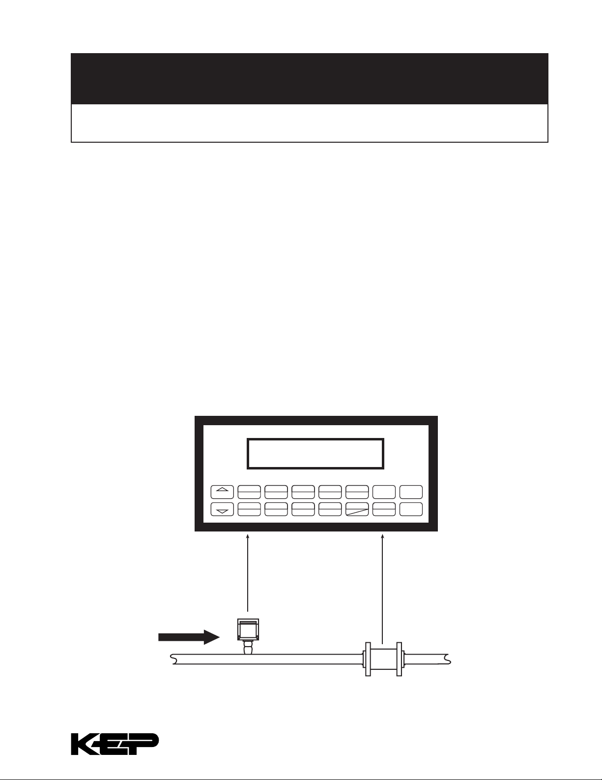
Pressure
Transmitter
Vortex
Flowmeter
Typical Steam Metering System
Using Vortex Flowmeter and Electronic Flow Computer
This document was created to aid in the explanation of the measurement of steam by a vortex steam
owmeter system and the related service operations.
General
A typical steam-metering system typically consists of several components:
• Vortex Flow Meter installed in the saturated steam line
• A static pressure transmitter to measure steam pressure
• A Flow Computer to compute the steam ow
• A Data Logger/Modem to monitor the customer site and provide trend information
NOTE: If remote metering is supported, a remote PC, modem, and remote metering software may be used
in conjunction with this system.
HELP TIP: The piping surrounding the location where the owmeter and related transmitters are installed is
called the “meter run”.
Tech Note#F049 06/10/10
KESSLER-ELLIS PRODUCTS 10 Industrial Way East, Eatontown, NJ 07724
800-631-2165 • 732-935-1320 • Fax 732-935-9344 • http://www.kep.com
Page 2

Equipment Selection
The owmeter is sized by the manufacturer, based on the expected line conditions and ow rate anticipated
in the application. This normally requires that the line size, steam pressure range and expected steam ow
rate range be known. The vortex owmeter is selected for steam service with a measurement range that
will meet or exceed the maximim owrate. The static pressure transmitter is selected for steam service with
a measurement range that will meet or exceed the range of static line pressure to be encountered in the
application. The ow computer performs the necessary calculations needed to compute the steam ow from
the electrical signals being fed into it. The datalogger and modem permit remote monitoring of the information
fed into the data logger. The information is sent to the datalogger by either the input measurement or the
computed outputs from the ow computer. A remote PC with modem can access the information either in the
data logger or in the current readings of the ow computer.
Factory Calibration
The ow meter, transmitters, ow computer, and data logger are calibrated by their respective manufacturer’s
prior to being supplied to a utility company, in accordance with the instructions provided when the units are
purchased.
Installation
During installation the owmeter and static pressure transmitters are installed in accordance with industry
guidelines and manufacturers’ instructions.
The individual calibration and setup documents provided by the manufacturers are reviewed.
Startup
During startup the individual components of the systems are setup so that they operate correctly.
For the transmitters this normally involves double-checking of each transmitter range and optional features
using a hand held terminal.
The ow computer is setup by entering the information on the owmeter and static pressure transmitter. In
addition, the items to be included in the data logger are also setup. This is usually done from the front keypad,
although connecting the device to a laptop and using a special program supplied by the manufacturer can
also be used. Setup may also be accomplished remotely via the modem connection.
The setup of each individual item is veried. For each measurement, there is a transmitter to scale and send
an electrical signal to the receivers that need this information. The scaling of each transmitter must also be set
into the corresponding ow computer input channel. If a change is made to one, it must be made to all.
The basic operation of the system can be veried by checking that the respective sensors are producing
the correct signals, based on the observed signal, the ow range setup in the sender and receiver of the
information, and the observed process conditions in the steam line. Signal simulators and multi-meters may
also be used.
There is a “low ow cutoff” that should be set to prevent the system from metering when no ow is present.
This also limits the low ow measurement range, so it is usually set to the lowest practical value.
Meter Readings
Meters may be read either locally by taking a reading from the ow computer, or remotely by taking a reading
from the ow computer via modem, or by reading the data logger. The operational status of the metering
system is also checked periodically.
KESSLER-ELLIS PRODUCTS 10 Industrial Way East, Eatontown, NJ 07724
800-631-2165 • 732-935-1320 • Fax 732-935-9344 • http://www.kep.com
Page 3

Servicing the Metering System
Often a utility will perform various inspections each year on each steam meter. Manufacturers of the
components used in a steam system provide a number of service and test aids for Service personnel that
permit them to interrogate a component to determine if it is operating properly. From time to time problems
may occur in any system. The transmitters ow computer, and data logger usually have some diagnostic
capability and can assist in problem detection and notication.
If it becomes necessary, for any reason, the owmeter may be changed out. This sometimes occurs when
the heating load changes or the actual steam range is different than the expected range as a result of
inaccurate sizing information. When a change out occurs the information on the new owmeter must also be
set into corresponding transmitter and the ow computer ow input channel. If a change is made to one, the
change must be made to all.
If a transmitter is changed by either replacement, re-scaling, or re-spanning then the new scaling of that
transmitter must also be set into corresponding ow computer input channel. If a change is made to one, the
change must be made to all.
Most utilities remove portions of the meter system from service after several years for recalibration. The ow
computer and data logger can usually be checked in place using simulators. They can be removed from
service if needed and replaced with another device that then must be setup for use as described earlier.
Inputting known pressure using a special hydrostatic pressure pump may check many pressure transmitters.
In other cases, the transmitters are replaced with a calibrated replacement unit
KEP Flow Computer
Kessler-Ellis Products (KEP) offers the Supertrol 2 Flow Computer for Steam Metering applications. It is
available in a variety of housings to suit a wide range of application environments.
SUPERtrol II
• “EZ Setup”- Guided Setup for First Time Users
• Liquid, Gas, Steam and Heat Flow Equations
• Utility Metering
• Menu Selectable Hardware & Software
Features
• Internal Data Logging Option
• Isolated Pulse and Analog Outputs Standard
• RS-232 Port Standard, RS-485 Optional
Windows™ Setup Software
• NX19 Gas Equations, Stacked DP Transmitters
KESSLER-ELLIS PRODUCTS 10 Industrial Way East, Eatontown, NJ 07724
800-631-2165 • 732-935-1320 • Fax 732-935-9344 • http://www.kep.com
• DDE Server & HMI Software Available
• Remote Metering by Wireless or Modem
• NEW! - Attractive Wall Mount Enclosure
 Loading...