

Page 1
ES-749
• “EZ Setup”- Guided Setup for First Time Users
• Liquid, Gas, Steam and Heat Flow Equations
• Utility Metering - Steam, Heating/Cooling, Chilled
Water, Natural Gas, Compressed Air
• Menu Selectable Hardware & Software Features
• Internal Data Logger
• Isolated Pulse and Analog Outputs Standard
• RS-232 Port Standard, Provides Power for Modem
• RS-485 with Modbus RTU Optional
• Internal Communication Card Option
Supports: BACnet IP, BACnet MS/TP, Metasys N2,
Modbus TCP, AB Ethernet IP, AB DF1, LonWorks*
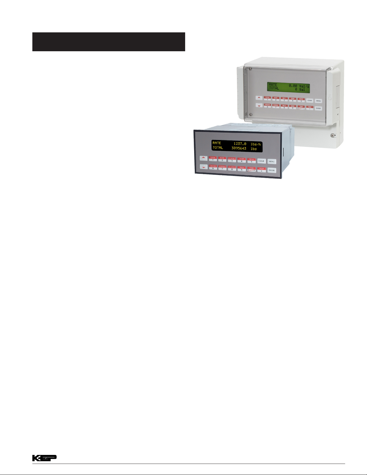
Utility Metering Flow Computer
• DDE Server & HMI Software Available
• Windows™ Setup Software
• NX19 Gas Equations, Stacked DP Transmitters
Description:
The ES-749 Flow Computer satisfies the instrument
requirements for a variety of owmeter types in liquid, gas, steam
and heat applications. Multiple ow equations are available in a
single instrument with many advanced features.
The alphanumeric display offers measured parameters in easy
to understand format. Manual access to measurements and
display scrolling is supported
The versatility of the Flow Computer permits a wide measure
of versatility within the instrument package. The various hardware
inputs and outputs can be “soft” assigned to meet a variety of
common application needs. The user “soft selects” the usage of
each input/output while conguring the instrument.
Applications Include:
Steam Mass, Steam Heat, Natural Gas, Fuel 0il, Compressed
Air, Chilled Water Only, Heated Water Only including Low
DeltaT Cutout.
The isolated analog output can be chosen to follow the volume
ow, corrected volume ow, mass ow, heat ow, temperature,
pressure, or density by means of a menu selection. Most hardware
features are assignable by this method.
The user can assign the standard RS-232 Serial Port for
external data logging, transaction printing, or for connection to a
modem for remote meter reading.
A Service or Test mode is provided to assist the user during
start-up system check out by monitoring inputs and exercising
outputs. The system setup can also be printed.
* LonWorks protocol requires a different module assembly from the
other available protocols. LonWorks is not eld selectable.
•
Remote Metering by External Wireless or Modem
• Attractive Wall Mount Enclosure Available
Specications:
Environmental
Operating Temperature: 0 to +50 C
Storage Temperature: -40 to +85 C
Humidity : 0-95% Non-condensing
Materials: UL, CSA, VDE approved
Display
Type: 2 lines of 20 characters
Types: Backlit LCD, OLED and VFD ordering options
Character Size: 0.2” nominal
User selectable label descriptors and units of measure
Keypad
Keypad Type: Membrane Keypad with 16 keys
Keypad Rating: Sealed to NEMA 4X / IP65
Enclosure
Enclosure Options: Panel, Wall, Explosion Proof
Size: See Dimensions
Depth behind panel: 6.5” including mating connector
Type: DIN
Materials: Plastic, UL94V-0, Flame retardant
Bezel: Textured per matt nish
Power Input
The factory equipped power option is internally fused. An
internal line to line lter capacitor is provided for added
transient suppression. MOV protection for surge transient is
also supported
Universal AC Power: 85 to 276 Vrms, 50/60 Hz
DC Power Option: 24 VDC (16 to 48 VDC)
Power Cosumption
AC Power: 6.5 V/A
DC Power: 300 mA max.
990239 08/14/17
Page 2

Flow Meter Types:
Linear: Vortex, Turbine, Positive Displacement, Magnetic,
GilFlo, ILVA, Mass Flow and others
Square Law: Orice, Venturi, Nozzle, V-Cone, Wedge,
Averaging Pitot, Target, Verabar, Accelabar
and others
Multi-Point Linearization: May be used with all owmeter
types. Including: 16 point, UVC and dynamic
compensation.
Flow Inputs:
Analog Input:
Accuracy: 0.02% FS at 20° C
Ranges
Voltage: 0-10 VDC, 0-5 VDC, 1-5 VDC
Current: 4-20 mA, 0-20 mA,
4-20 mA stacked, 0-20 mA stacked
Basic Measurement Resolution: 16 bit
Update Rate: 4 updates/sec
Automatic Fault detection: Signal over/under-range,
Current Loop Broken
Calibration: Operator assisted learn mode
Extended calibration: Learns Zero and Full
Scale of each range
Fault Protection:
Fast Transient: 500 V Protection (capacitive
clamp)
Reverse Polarity: No ill effects
Over-Voltage Limit: 50 VDC Over voltage
protection
Over-Current Protection: Internally current limited
protected to 24VDC
Pulse Inputs:
Number of Flow Inputs: one
Input Impedance: 10 k Ω nominal
Trigger Level: (menu selectable)
High Level Input
Logic On: 2.5 to 30 VDC
Logic Off: 0 to 2 VDC
Low Level Input (mag pickup)
Selectable sensitivity: 10 mV and 100 mV
Minimum Count Speed: 0.25 Hz (to maintain rate
display)
Maximum Count Speed: Selectable: 0 to 50 kHz
Overvoltage Protection: 50 VDC
Temperature, Pressure, Density Inputs
The compensation inputs usage are menu selectable
for temperature, temperature 2, pressure, density or
not used.
Calibration: Operator assisted learn mode
Operation: Ratiometric
Accuracy: 0.02% FS at 20° C
Basic Measurement Resolution: 16 bit
Update Rate: 2 updates/sec minimum
Automatic Fault detection:
Signal Over-range/under-range
Current Loop Broken
RTD short
RTD open
Reverse Polarity: No ill effects
Over-Current Limit
(current input)Internally limited to protect input to
24 VDC)
Available Input Ranges
Current: 4-20 mA, 0-20 mA
Resistance: 100 Ohms DIN RTD
100 Ohm DIN RTD (DIN 43-760, BS 1904):
Three Wire Lead Compensation
Internal RTD linearization learns ice point
resistance
1 mA Excitation current with reverse polarity
protection
Temperature Resolution: 0.1° C
Temperature Accuracy: ± 0.5° C
Stored Information (ROM)
Steam Tables (saturated & superheated),
Fluid Properties: Water, Air, Natural Gas or Generic
User Entered Stored Information (EEPROM / Nonvolatile
RAM)
Transmitter Ranges, Signal Types
Fluid Properties
(specic gravity, expansion factor, specic heat,
viscosity, isentropic exponent, combustion heating
value, Z factor)
Units Selections (English/Metric)
Language Translations (optional)
Kessler-Ellis Products • 10 Industrial Way East • Eatontown, NJ 07724 • 800-631-2165 or 732-935-1320 • www.kep.com Kessler-Ellis Products • 10 Industrial Way East • Eatontown, NJ 07724 • 800-631-2165 or 732-935-1320 • www.kep.com
Page 3

Excitation Voltage
13
PULSE OUTPUT (+)
PULSE OUTPUT (-)
ANALOG OUTPUT COMMON (-)
ANALOG OUTPUT 2 (+)
RLY1
RLY2
AC LINE
AC LINE24
18 COM
19
20
21
22
23
NC
NC
COM
NO
14
15
16
17 NO
POWER IN
DC (-)
DC (+)
PULSE IN
DC OUTPUT
COMMON
RTD EXCIT (+)
RTD SENS (+)
RTD SENS (-)
8
9
10
11
12
2
3
4
5
6
7
1
TEMPERATURE
Iin (+)
Vin (+)
Iin (+)
IN
IN
FLOW
RTD EXCIT (+)
RTD SENS (+)
RTD SENS (-)
DC OUTPUT
PRESSURE
(TEMP 2)
Iin (+)
IN
ANALOG OUTPUT 1 (+)
- - - - - - - - - -
24 VDC @ 100 mA (fault protected)
Relay Outputs
The relay outputs usage is menu assignable to
(Individually for each relay) Hi/Lo Rate Alarm, Hi/Lo
Temperature Alarm, Hi/Lo Pressure Alarm, Pulse Output
(pulse options), Wet Steam or General purpose warning
(security).
Number of relays: 2 (3 optional)
Contact Style: Form C contacts
Contact Ratings: 240 V, 5 amp
Analog Outputs
The analog outputs are menu assignable to correspond
to the Uncompensated Volume Rate, Corrected Volume
Rate, Mass Rate, Heat Rate, Temperature, Density, or
Pressure.
Number of Outputs: 2
Type: Isolated Current Sourcing (shared common)
Available Ranges: 0-20 mA, 4-20 mA (menu
selectable)
Resolution: 16 bit
Accuracy: 0.05% FS at 20 Degrees C
Update Rate: 5 updates/sec
Temperature Drift: Less than 200 ppm/C
Maximum Load: 1000 ohms
Compliance Effect: Less than .05% Span
60 Hz rejection: 40 dB minimum
EMI: No effect at 3 V/M
Calibration: Operator assisted Learn Mode
Averaging: User entry of DSP Averaging constant to
cause a smooth control action
Listing: CE Approved, UL/CSA Pending
Data Logging
The data logger captures print list information to internal
storage for approximately 5000 transactions. This
information can be used for later uploading or printing.
Storage format is selectable for Comma-Carriage Return
or Printer formats.
Isolated Pulse output
The isolated pulse output is menu assignable to
Uncompensated Volume Total, Compensated Volume
Total, Heat Total or Mass Total.
Pulse Output Form (menu selectable): Open Collector
NPN or
24 VDC voltage pulse
Nominal On Voltage: 24 VDC
Maximum Sink Current: 25 mA
Maximum Source Current: 25 mA
Maximum Off Voltage: 30 VDC
Saturation Voltage: 0.4 VDC
Pulse Duration: User selectable
Pulse output buffer: 8 bit
Fault Protection
Reverse polarity:
Shunt Diodes
Over-current Protected
Over-voltage Protected
Real Time Clock
The Flow Computer is equipped with a non-volatile real
time clock with display of time and date.
Format:
24 hour format for time
Day, Month, Year for date
Terminal Designations
Serial Communication
The serial port can be used for printing, datalogging,
modem connection and communication with a computer.
Power is provided for KEP’s MPP2400N (modem)
communication accessory.
RS-232:
Device ID: 01-99
Baud Rates: 300, 1200, 2400, 9600
Parity: None, Odd, Even
Handshaking: None, Software, Hardware
Print Setup: Congurable print list and formatting,
RS-485:
Device ID: 01-247
Baud Rates: 300, 600, 1200, 2400, 4800, 9600,
19200
Parity: None, Odd, Even
Protocol: Modbus RTU (Half Duplex)
Compatible with external dataloggers.
Page 4

Internal Multi-protocol Communication Card Option
FEATURES
• Internal communication card eliminates the need for external
protocol converters.
• Supports: BACnet IP, BACnet MS/TP, Metasys N2, Modbus
TCP, AB Ethernet IP, AB DF1, LonWorks*
• Easy to congure via the Web Interface.
• Dedicated internal LonWorks is also available
• Dedicated internal RS485 Modbus RTU is also available
DESCRIPTION
The multi-protocol communication card is an internal, high
performance, Building Management System communication
solution for the ST2 ow computer family. The card provides an
instant interface, enabling the KEP ow computers to communi-
cate with multiple BMS protocols, including:
• BACnet MS/TP
• BACnet IP
• Modbus TCP
• Metasys N2
• AB DF1
• AB EtherNet/IP
• LonWorks*
CONFIGURATION
Use a web browser to locate the internal web page and congure the settings. The detailed settings vary with the different
communication protocols. Only one communication port/proto-
col can be used. A web browser is also used to congure the
site specic settings for each instrument
Fig 1
Top view of multi-protocol card installed on ES749 mother board
Quad Digital Input
(ES762 only)
RS-232
RS-485
Ethernet
Fig 2
Communication ports are available for RS-485 and Ethernet
Rear view of ES749 case.
* LonWorks protocol requires a different module assembly from the other available protocols. LonWorks is not eld selectable.
Kessler-Ellis Products • 10 Industrial Way East • Eatontown, NJ 07724 • 800-631-2165 or 732-935-1320 • www.kep.com Kessler-Ellis Products • 10 Industrial Way East • Eatontown, NJ 07724 • 800-631-2165 or 732-935-1320 • www.kep.com
Page 5

1
50000
47808
COV_Disable
-
Page
1
of
1
The Web Interface makes it easy to congure.
Configuration Parameters
Submit
Submit
Add
Submit
Submit
Submit
Remove
Sample screen shot of web interface conguration
Page 6

Dimensions
1.10
(28)
1.10
(28)
7.8 (198)
0.59
(14)
0.75” Conduit Knockouts
(5 places)
1.06
(27)
9.4 (238)
8.4 (213.4)
4.13 (105)
2.33 (59)
0.385
(9.8)
Security Tag
Provisions
0.625”ø
0.75”ø 5 places
1.10
(28)
1.10
(28)
1.10
(28)
1.10
(28)
1.10
(28)
1.10
(28)
0.472
(12)
0.75
(19)
0.63
(16)
Wall Mount (option W)
5.67 (144)
3.43
(87)
RATE
TOTAL
267395.749
PRE 1
RATE
TOTAL
START
1
GRAND6SCROLL7PRE 28DENS
STOP
3
2
6.18 (157)
Dotted Line Shows Optional Bezel Kit
0.28 (7.2)
6.15 (156)
0.4 (10)
5.43
(138)
Panel
Cutout
147.43
TEMP
4
9
GPM
GAL
PRINT
CLEAR•MENU
5
HELP
TIME
0
ENTER
–
2.68
(68)
0.5
(13)
2.83
(72)
Dimensions are in inches (mm)
Kessler-Ellis Products • 10 Industrial Way East • Eatontown, NJ 07724 • 800-631-2165 or 732-935-1320 • www.kep.com Kessler-Ellis Products • 10 Industrial Way East • Eatontown, NJ 07724 • 800-631-2165 or 732-935-1320 • www.kep.com
Page 7

NEMA4 Wall Mount (mounting option N)
Explosion Proof Mount (mounting option E)
Page 8

Ordering Information
ES749
Example ES749 L 1 0 P TB
Series:
ES749ST2 = ST2 Special
Display Type:
L= LCD
O= OLED
V= VFD
Input Type:
1= 85 to 276 VAC
3= 24 VDC
Network Card:
0= None
1= RS485/Modbus
3= COM CARD with Multi-Protocol
Specify protocol (example: 3 BAC/IP)
BAC/IP = BACnet IP
BACMS/TP = BACnet MS/TP
MOD/IP = Modbus TCP/IP
METASYS/N2 = Metasys N2
ABDF1 = AB DF1
ABETH/IP = AB EtherNet/IP
4= COM CARD with LonWorks Protocol
Specify protocol (example: 4 LONWORKS)
Factory conguration of network card settings
Mounting:
P= Panel Mount
N= NEMA 4 Wall Mount (see MS811)
W= NEMA 12/13 Wall Mount w/ Clear Cover
E= Explosion Proof (No Button Access)
Options:
9 = 3 Relay Super Chip
(Includes: Peak Demand, AGA NX-19 calculation for natural gas,
Stacked DP option, Datalogger option, Stack Emissions Controller
option,Manifold Flowmeter Controller option)
10 = 2 Relay Super Chip
(Includes: Peak Demand, AGA NX-19 calculation for natural gas,
Stacked DP option, Datalogger option, Stack Emissions Controller
option,Manifold Flowmeter Controller option)
13 = Superchip; 2 relay, Positive heat only
14 = Superchip; 3 relay, Positive heat only
22 = Superchip; 2 relay, For use with 4 terminal
multi-variable vortex meters
26 = Superchip; 3 relay, For use with 4 terminal
multi-variable vortex meters
TM = Trap monitor RS485 network card
IM = Internal Modem
IM-56K = 56K Internal Secure Modem
M = Modem Power Option
ET= Extended Temperature LCD Display
TB= RS485 Terminal Block for Panel Mount Enclosure
Accessories:
ST2 SETUP PRO - Advanced setup software for ST2 family
OPC/DDE Server for RS232 Port available, see KWP-UCOND0-PRD
OPC/DDE Server for Modbus Suite available, see KWP-MDBUS0-PRD
Modem Available, see MPP-56KN, MPP-2400 and MPP-2400N
Serial printer available, see P20, P220, P295
Ethernet Port Server available, see IEPS
RS-422/485 to RS-232 Communication Adaptor available, see CA285
RS232 Extender Cable: P/N=13220-<length in inches>
Remote metering and data collection software available, see TROLlink
Kessler-Ellis Products • 10 Industrial Way East • Eatontown, NJ 07724 • 800-631-2165 or 732-935-1320 • www.kep.com Kessler-Ellis Products • 10 Industrial Way East • Eatontown, NJ 07724 • 800-631-2165 or 732-935-1320 • www.kep.com
 Loading...