

Page 1

BAT R/T Millennium-S1
http : / /www. k ep.com
Ratemeter / Totalizer with RS232 Serial Port
Installation and Operating Instructions
KESSLER-ELLIS PRODUCTS
99982 11/10/15
10 Industrial Way East
Eatontown, NJ 07724
800-631-2165 • 732-935-1320
Fax: 732-935-9344
Page 2

Page 3

CONTENTS
Specications ................................................................... 1
Battery Installation and Replacement .............................. 3
Dimensions ....................................................................... 4
Theory of Operation .......................................................... 5
Wiring ............................................................................... 5
Typical Applications ..........................................................5
Denitions ......................................................................... 6
Programming Flowchart ................................................... 9
Operation .......................................................................... 12
Error Messages ................................................................ 13
Analog Output Calibration ................................................ 13
Warranty ...........................................................................14
Decoding Part Number ..................................................... 14
Page 4

Page 5

SPECIFICATIONS
Description
Featuring 5 digits of rate and 8 digits of total, the BAT
R/T Millennium edition (BATRT-M) is a battery or loop
powered indicator capable of accepting magnetic pickup,
DC pulse and switch closure inputs from pulse produc-
ing owmeters. The unit can be ordered with an optional
4-20mA output. The BATRT-M uses the 4-20mA loop to
provide power when this output is used.
Specications
DISPLAY:
Rate Display: (selectable decimal)
5 Digits (99999), 0.35” High, Display updates once per
second with battery power, 8X per second with DC or
Loop power
Rate Descriptors: /SEC, /MIN, /HR
/MIN, /HR, /DAY with “D” option
Min. Input Frequency: 0.01 Hz to 10 Hz (selectable
delay of 0.1 to 99.9 seconds) Selectable Rate Display
Damping
Totalizer Display: (selectable decimal)
8 Digits (99999999), 0.2” High
Totalizer Descriptors: GAL, LIT, FT3, M3, “blank”
GAL, BBL, MCF, M3, “blank” with
“D” option
Warning Displays: Low battery warning
PULSE OUTPUT:
The pulse output advances with the least signicant
digit of the totalizer or decimal multiples there of (see
Pulse scale divider).
Type: Isolated photomos relay
Max. voltage (off state): 30 VDC
Current (on state): 100mA
Pulse Duration: Selectable 0.5, 0.25, 0.125, 0.0625
seconds
Pulse Scale divider (Pulscale): User selectable, ÷1,
÷10, ÷100 or OFF
NOTE: Select OFF for max. battery life.
ACCURACY:
0.01% Reading, ±1 count
Temperature Drift: 50 ppm/°C Worst Case
SAFETY LISTINGS (Mounting Styles 3, 3NE, 3SS):
CSA File 091109 (cert. 1120094)
UL/C-UL File E225832
CLASS 1, DIV 1, GROUPS B, C, D
Additional "enclosure only" approvals available for ATEX and
IEC
CAUTION; KEEP COVER TIGHT WHILE CIRCUITS ARE
ALIVE, A SEAL SHALL BE INSTALLED WITHIN
450mm (18 in) OF THE ENCLOSURE WHEN USED
IN GROUP B ATMOSPHERES AND WITHIN 1.5m (5
ft) WHEN USED IN GROUP C ATMOSPHERE
ENVIRONMENTAL:
OPERATING TEMPERATURE
-4°F (-20°C) to + 158°F (70°C)
Extended Temp: -22°F (-30°C) to + 158°F (70°C)
HUMIDITY
0 - 90% Noncondensing
MOUNTING STYLES:
0- Circuit Board- OEM option (consult factory)
1- Panel Mount - NEMA 4X Front
2- Wall Mount - NEMA 4X Enclosure
(keypad mounted behind clear cover)
3- Explosion Proof - Class I, Division I, Groups B, C & D
Class II, Division I, Groups E, F & G
3ΝΕ- Explosion Proof - White, Includes Third Conduit Entry
Class I, Division I, Groups B, C & D
Class II, Division I, Groups E, F & G
3SS- Explosion Proof - Stainless Steel
Class I, Division I, Groups B, C & D
Class II, Division I, Groups E, F & G
5- Wall Mount - NEMA 4X Enclosure
(keypad mounted on cover)
6- Double Ended Explosion Proof -
Class I, Division I, Groups B, C & D
Class II, Division I, Groups E, F & G
(contact factory for details)
NOTE: Meter mounting kits available for styles 2, 3, 5 and 6
Consult Factory
NPUTS:
MAGNETIC PICKUP INPUT
Frequency Range: 0 to 3500 Hz
Trigger Sensitivity: 10 mV p-p
Over Voltage Protected: ± 30 VDC
OPTO-ISOLATED DC PULSE INPUT
High (logic 1): 4-30 VDC
Low (logic 0): Less Than 1 VDC
Minimum Current: .5 mA
Hysteresis: 0.4 VDC
Frequency Range: 0 to 5 kHz
Min. Pulse Width: 0.1 msec
CONTACT CLOSURE INPUT (contact closure to common)
Internal Pullup Resistor: 100 KΩ to +3.6 VDC
High (logic 1): Open or 4-30 VDC
Low (logic 0): Less Than .5 VDC
Internal Switch Debounce Filter: 0 to 40 Hz
NOTE: Sustained contact closure will shorten battery life.
RESET INPUT (contact closure to common)
Internal Pullup Resistor: 100 KΩ to +3.6 VDC
High (logic 1): Open or 4-30 VDC
Low (logic 0): Less Than .5 VDC
Minimum On : 25 msec
NOTE: Sustained contact closure will shorten battery life.
K-FACTOR
Range: 0.001 to 99999999
Decimal Point Locations: XXXX.XXXX to XXXXXXXX
CAUTION; PLUG ANY UNUSED CONDUIT ENTRIES WITH A
CERTIFIED CONDUIT PLUG
AVERTIR; GARDER LA COUVERTURE TENDUE PENDANT
QUE CIRCUITS SONT VIVANTS , UN CACHET
SERA INSTALLE DANS 450 mm (18 dans) DE
LA CLOTURE QUAND UTILISE DANS LES
ATMOSPHERES DE B DE GROUPE ET DANS 1.5m
(5 ft) QUAND UTILISE DANS L’ATMOSPHERE DE
C DE GROUPE
AVERTIR; BOUCHER LES ENTREES INUTILISEES DE
CONDUIT AVEC UN BOUCHON DE CONDUIT
CERTIFIE
* Slow input pulse rates, large delay setting and internal math
operations may delay the update rate of information.
20 Point Linearization Option (10 Point with Data Logger option)
This feature allows the user to enter 20 different frequencies
with 20 different corresponding K-Factors to linearize non linear signals.
ANALOG OUTPUT OPTION:
Type: 4-20 mA follows rate display, Two wire hookup
Accuracy: 0.025% Full Scale at 20° C
Temperature Drift:
50 ppm/°C Typical
Reverse Polarity Protected
Update Rate: 8 times/second
NOTE: The BATRT-M uses the 4-20 mA loop power as its pri-
mary power source when this option is used. The battery
is still required for standby battery operation.
1
Page 6
SPECIFICATIONS
T
Power Adaptor
(continued)
Power:
BATTERY POWERED
Supplied with 1 or 2 C size Lithium battery pack.
EXTERNAL POWER INPUT
Voltage: 8.5 to 30 VDC
Current: Less than 5 mA
Supplied with 1 C size lithium battery
Protection: Reverse Polarity Protection on DC Power Input
LOOP POWERED
Voltage: 8.5 to 30 VDC
Supplied with 1 or 2 C size lithium battery(ies)
Protection: Reverse Polarity Protection on Current Loop
Loop Burden: 8.5V maximum
BATTERY LIFE EXPECTANCY:
Expected Years of Operation for BATRT-M of various powering
options at equipment duty cycles
MODEL RUN TIME
Idle 2hrs/day 8hrs/day 24hrs/day
BATRT-M-A 10 yrs 10 yrs 10 yrs 9.1 yrs
BATRT-M-A-4 10 yrs 10 yrs 10 yrs 8.4 yrs
BATRT-M -B/C Indenite operation when externally powered
External or loop power
NOTE: Battery shelf life is rated at 10 years by manufacturer
Life expectancy based on rated battery capacity at
20°C
The above table is shown with pulse output inactive.
Use of pulse output shortens battery life.
Example: A pulse output of 0.06 sec. duration, once per sec-
ond, would derate the battery life by 20%.
IDATA STORAGE:
Setup Information: Stored in ash memory
Totalizer: Stored in battery backed RAM but can be saved to
ash memory by operator for recall after battery change out.
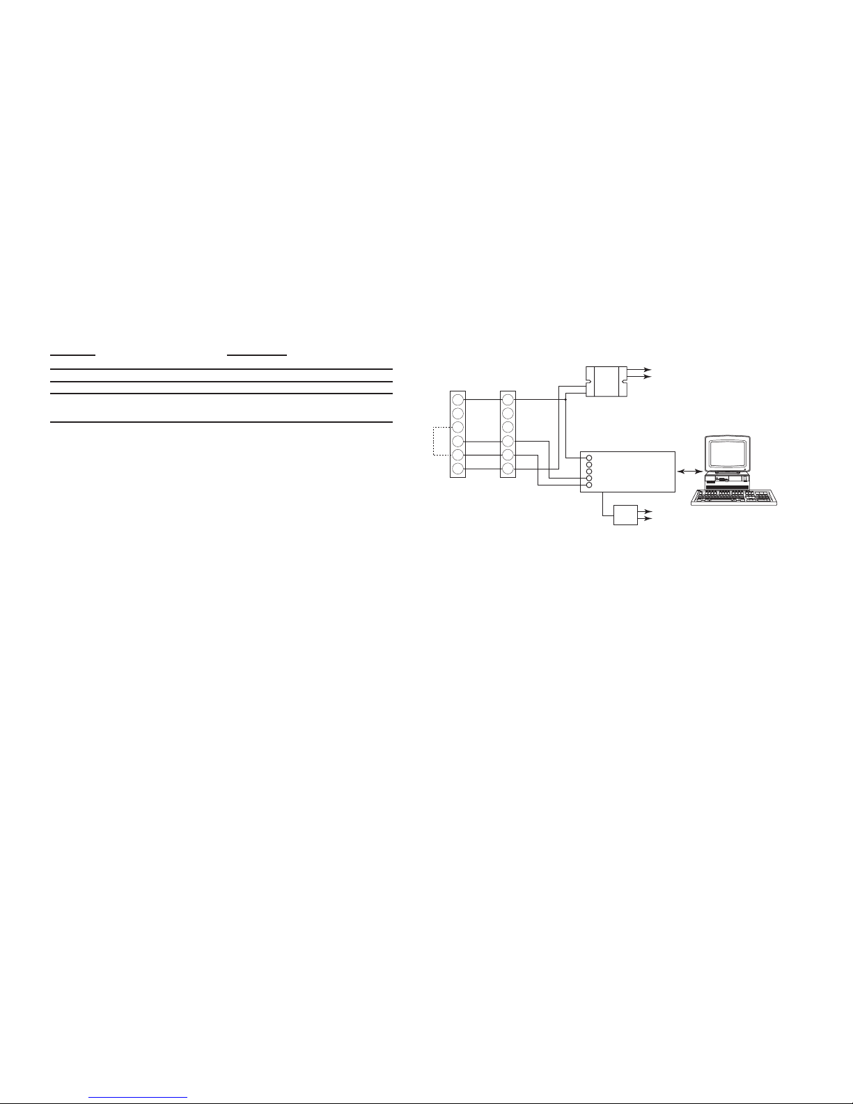
COMMUNICATIONS OPTION (S1):
RS232 SERIAL SETUP SOFTWARE OPTION:
This option enables you to access a variety of process param-
eters through serial communications. PC compatible communications software is included with this option. With this
software and a BAT R/T-M Serial Adapter Cable (BSAC1) you
will be able to setup the BAT R/T-M through your PC.
RS-485 MODBUS and DATA LOGGER OPTION (S2):
The optional RS-485 card utilizes Modbus RTU protocol to ac-
cess a variety of process parameters. The Data Logger stores
the totalizer to ash memory once every 24 hours at the time
you set. The data logger can hold 27 days of totals, on the
28th day the oldest total in the logger is dropped. Requires external DC power: 6-28VDC (input is reverse polarity protected)
Current Draw:
Receiving: 2 mA
Transmitting: 125 mA (instantaneous peak)
BATRT-M
Unit 2
Connect 16 to 14
for optional
erminating Resistor
BATRT-M
Unit 1
18
17
16
15
14
13
18
17
16
15
14
13
(+)
(–)
24 VDC
Power Supply
Model
115-24
G
R R +
T T +
CA285
Model
CA285
115 VAC
115 VAC
PC with
RS-232 Port
2
Page 7

BATTERY INSTALLATION and REPLACEMENT
654321
Rear View
Battery
789101112
BATPACK
Connector
Battery Installation:
All BATRTM models are shipped without the battery(ies) installed. This preserves battery life when the unit is not
in service. When using external BATPACK, mount within 12" and plug connector into 3 position square posts (see
Fig 1). Polarity is not a concern because center is common.
To install the battery, begin by locating the battery holder. The BATRTM-2, 3, 3NE, 3SS, 5 and 6 require opening the
enclosure cover and removing the BATRTM to expose the battery holder.
The plus terminal of the battery is marked with a (+) symbol stamped into the battery holder. Be sure to install the
battery(ies) correctly.
Install battery(ies) to begin setup procedure. See Programming Flowchart to setup desired operating parameters.
Battery Replacement:
The BAT R/T-M has a battery monitor feature which illuminates when the lithium battery voltage approaches its
end of life. A descriptor, “BAT”, illuminates when the battery voltage falls below this predetermined value. The low
battery detector operates correctly with all power options.
The battery, or batteries, should be replaced within several weeks of the rst occurrence of low battery warning,
“BAT”. Left unattended, the unit may become inaccurate, cease to operate or malfunction.
Before replacing the battery(ies), Press the ← (left arrow) key to save the totalizer. The display will show "SAVE
TOTAL". This will save the current total value and the total will resume from this value when the new battery(ies)
is(are) installed. NOTE: If the display starts to ash after the "SAvE totAL" message times out, press the "E" (enter)
key. If the message "E FLASH" is displayed, then there was not enough power left to save the setup and totalizer
to ash memory. At this point you must record the totalizer and setup information and re-enter the setup data after
the new battery(ies) is(are) installed.
Install new battery(ies) as described above.
Fig 1
Jumper momentarily to reset unit to factory de-
fault values.
3
Page 8

DIMENSIONS
3.062" (77.77)
Dia. Cutout
3.582" Dia. Bolt Circle
.125" Holes to be 120° Apart
Outside Dotted Line Shows
Outside Panel Dimension
(4.00" Diameter)
120°
.10
(2.54)
4.00
(101.6)
1.7
(43)
2.875
(73)
Panel
Cutout
4.63
(117)
3/4 NPT
(2) HLS
5.00
(127)
5/16
4.25
(108)
5.25
(133)
E
M
5.00
(127)
To access terminals, unscrew cover and loosen 2 panel screws.
Terminals are on bottom side of PC board.
Optional 3rd
Conduit Entry
4.92
(125)
4.33
(110)
4.33 (110)
#8 Screw Mounting holes molded directly under cover
screws. Max. screw head .29" (Typ. 4 places)
E
M
.98
(25)
1.97
(50)
.18(5)
.43
(11)
BOTTOM VIEW
To access terminals, remove cover
and 4 panel screws. Terminals are
on bottom side of PC board.
Panel Screws
4.92(125)
TOP VIEW (PANEL INSTALLED)
Optional HF2, HF3
Hub Fitting
Optional H2, H3
Hub Holes
E
M
3.0120 DIAMETER
.900
(22.8)
.992
(25.2)
Mounting holes
.125 Drill (2 places)
.438 Nylon Spacer
Supplied
1.8
(46)
2.875
(73)
.10
(2.5)
.438
(11.1)
.900
(22.8)
.992
(25.2)
2.40
(61)
2.20 (56)
0.95 (24)
0.30 max. (7.6)
0.15 (3.8)
Battery
Mounting Hole
0.125 (3) dia.
5.10
(130)
4.45
(113)
4.45 (113)
#8 Screw Mounting holes molded directly under cover
screws. Max. screw head .29" (Typ. 4 places)
E
M
1.1
(28)
1.97
(50)
.18(5)
BOTTOM VIEW
5.10(130)
TOP VIEW (PANEL INSTALLED)
Optional HF2, HF3
Hub Fitting
Optional H2, H3
Hub Holes
.36
(9.2)
To access terminals, remove cover.
Terminals are on bottom side of PC board.
2.25"
BATPACK
BATRT-M-0
BATRT-M-1
BATRT-M-3
BATRT-M-3NE
Ø 4.331 (110)
Glass
Window
Locking
Screw
A
1.575
Dimensions in inches (mm)
(40)
ETM-4
EARTH
TERMINAL
A
4.291 (109)
0.984
(25)
3RD Conduit
Entry Standard
7 full threads
3/4 NPT
4.961 (126)
4.941 (125.5)
3/4 NPT
7 full threads
5.71 (145)
4.528 (115)
Ø 0.27 (7)
7 full threads
3/4 NPT
BATRT-M-2
NOTE: Additional entry holes may be provided on styles 2 and 5.
BATRT-M-3SS
BATRT-M-5
BATRT-M-6
4
5.5"
2.375"
5.375"
1.188"
5.625"
Page 9

Flow Total =
Sum of Input Pulses
FAC
Flow Rate Indication =
Input Frequency
FAC
x Time Scaler
Where Time Scaler is equal to: 1 for rate per second read out
60 for rate per minute read out
3600 for rate per hour read out
86400 for rate per day read out
“D” option Only
THEORY OF OPERATION
Remote
Reset Switch
12 VDC
Power
Supply
+
-
1 Mag Input 1
2 Mag Input 2
3 Shield/Common
4 Reset Input
5 Contact Input
6 Common/ DC In (-)
Turbine Meter with
Mag Pickup
6 5 4 3 2 1
MAG INPUT / DC POWERED
DC In (+) 12
Not Used (-) 11
Opto Input (+) 10
Opto Input (-) 9
Opto Out (+) 8
Opto Out (-) 7
789101112
KEP
115-12
or
Ext. Battery
(Power option A or B)
Flowmeter with
Switch Closure Output
DC In (+) 12
Not Used 11
Opto Input (+) 10
Opto Input (-) 9
Opto Out (+) 8
Opto Out (-) 7
1 Mag Input 1
2 Mag Input 2
3 Shield/Common
4 Reset Input
5 Contact Input
6 Common/ DC In (-)
6 5 4 3 2 1
CONTACT INPUT / PULSE OUTPUT / BATTERY POWERED
123456
789101112
(Power option A or B)
Remote
Reset Switch
1 Mag Input 1
2 Mag Input 2
3 Shield/Common
4 Reset Input
5 Contact Input
6 Common/ DC In (-)
Turbine Meter with
Mag Pickup
6 5 4 3 2 1
MAG INPUT / BATPACK POWERED
DC In (+) 12
Not Used(-) 11
Opto Input (+) 10
Opto Input (-) 9
Opto Out (+) 8
Opto Out (-) 7
789101112
BATPACK PLUGIN
CONNECTOR
BATPACK
(Power option A or B)
(Power option C or AC)
Turbine Meter with
Mag Pickup
1 Mag Input 1
2 Mag Input 2
3 Shield/Common
4 Reset Input
5 Contact Input
6 Common
6 5 4 3 2 1
+
-
Strip Chart
Recorder
MAG INPUT / 4-20 mA LOOP POWERED
4-20mA (+)(+) 12
4-20mA (-) 11
Opto Input (+) 10
Opto Input (-) 9
Opto Out (+) 8
Opto Out (-) 7
789101112
24 VDC
Power
Supply
+
-
Flow rate equation: Flow total equation:
20 Point Linearization Option:
A 20 point linearization table is used to construct a curve describing the relationship of K-Factor and input frequency.
The measured input frequency is used to access the table. A linear interpolation of adjacent point pairs is used to
arrive at the K-Factor at that input frequency. The ow rate and total are then computed based upon the K-Factor
for that measurement sample.
NOTE: For best performance and resolution choose as many decimal places as possible in the K-Factor.
Example: Enter a K-Factor of 1 as 1.000.
WIRING
Several typical applications of the BAT R/T-M are shown below. Please observe that the various pulse inputs and
power options may be intermixed in many ways to solve common applications. The isolated pulse output may be
freely used so long as proper polarity is observed.
Caution: When 4-20 mA loop option is provided, the power wiring to the loop power option should always be to
terminals (+) 12 and (-) 11. Accidental wiring to (+) 12 and (-)6 should be avoided since excessive current
ow may result with power option "C".
Caution: The magnetic pickup input and contact closure input require isolated sensors for proper operation. Ac-
cidental connections to earth may result in erroneous operation of the analog output and/or excessive
current ow with power option "C".
Caution: Accidental connections from circuit common (3 or 6) to earth or terminal (11) may result in erroneous
operation of the analog output and/or excessive current ow with power option "C".
TYPICAL APPLICATIONS
5
Page 10

DEFINITIONS
Save Total: (Save Total) Press the E key while the unit is running to save the total value. The display will show
"save total" for a few seconds. This is a very useful "scratch pad" to save and restore total when replacing
the battery(ies)
ent Code: (enter code) This prompt will only appear if the panel lock is ON. Press the ↑ key to increment each digit.
Press the ← key to step to the next digit to the left. Press the E key to enter the 5 digit code. If the entered
code is correct, the display will advance to the next menu prompt (CLr tot). If incorrect, the display will return
to the run mode.
Clr tot: (clear total) Clears (resets) the totalizer. Press the E key to clear the total and return to the run mode. Press
the M key to skip and advance to the next menu selection.
fdeC: (factor decimal) Sets the decimal location for the factor. This location is restricted to 3 places (99.999). The use
of this decimal automatically limits the number of decimal locations allowable in the rate and total to acceptable
ranges. Press the ← key to move the decimal. Press the E key to select the displayed decimal location.
NOTE: For best performance and resolution choose as many decimal places as possible in the K-Factor.
Example: Enter a K-Factor of 1 as 1.000.
faC lInear/20poInt: (factor type) This prompt will only appear if the unit is ordered with the 20 point linearization op-
tion. The 20 poInt linearization selection is recommended for ow meters whose K-factors change with different
ow rates. This selection allows users to enter up to 20 different frequencies with 20 corresponding K-factors for
different ow rates. The lInear setting is used for ow meters whose output is linear over its' entire operating
ow range. Press the ↑ key to step to the desired choice. Press the E key to enter the displayed factor type.
No / yes set Pnts: (set 20 point?) This prompt allows the user to skip the 20 point setup routine. Select yes for
initial setup or to change the present 20 point values. Select No to skip and keep the existing values.
faC : (factor) This prompt appears on all units with linear inputs. The Factor is the number of pulses per unit volume
for the ow sensor. The pulses/unit volume is implied by the totalizer descriptor when a descriptor is used. The
implied units for the Factor are then as follows:
Standard "D" Option
GAL pulses/gallon GAL pulses/gallon
LIT pulses/liter BBL pulses/BBL
FT3 pulses/ft3 MCF pulses/MCF
M3 pulses/M3 M3 pulses/M3
Factors from 0.0001 to 99999999 may be used. A "0" value for the factor is not allowed and the unit will default
to "1" in LSD if a "0" entry is attempted . The factor is displayed on the subsidiary (lower) display. Press the ↑
key to increment each digit. Press the ← key to step to the next digit to the left. Press the E key to enter the
displayed factor.
fr# : (frequency for point #) This prompt will only appear when 20 point selected. It sets the frequency for each of
the 20 points (#). Press the ↑ key to increment each digit. Press the ← key to step to the next digit to the left.
Press the E key to enter the desired frequency for point #.
faC# : (factor for point #) This prompt will only appear when 20 point selected. It sets the factor for each of the 20
points (#). Press the ↑ key to increment each digit. Press the ← key to step to the next digit to the left. Press
the E key to enter the desired factor for point #.
NOTE: The display will advance to the next point (Fr#) after each entry of the Fr & Fac until all 20 points are com-
plete. entering a 0 in the Fr or fac setting will advance the display to the next menu prompt (tdec).
6
Page 11

DEFINITIONS
(continued)
tdeC: (totalizer decimal) Sets the decimal location for the totalizer. The totalizer decimal is not a dummy decimal
and will scale the totalizer display accordingly. (i.e. if the tdec is set in the tenths position (1234567.8), 100 will
be displayed as 100.0). The location of the decimal point allows for greater resolution of both the totalizer display
and the pulse output. The pulse output advances at a rate dependent on the least signicant digit of the total-
izer. The totalizer decimal location is restricted to a maximum of 4 places (1234.5678). However, the number
of totalizer decimal locations allowable is reduced with each decimal place added to the factor decimal. Press
the ← key to move the decimal. Press the E key to enter the displayed decimal location.
Note: The selection of the factor decimal point limits the available selections for the number of decimal
points available for the totalizer. This is automatic. Enter your selection of the Factor’s decimal point
before entering the totalizer decimal point to assure the proper selection of the totalizer decimal
point has been made.
tot desC: (totalizer descriptor) This allows you to illuminate one of the available descriptors on the display (STD:
GAL, LIT, FT3, M3 or "blank"; "D" option: GAL, BBL, MCF, M3, "blank"). Press the ↑ key to select the descrip-
tor. Press the E key to enter the selected descriptor.
r sCale: (ratemeter scaling) Sets the timebase for the rate readout. Choose rate per hour (Hrs), minutes (nnIn)
or seconds (seC). (Days will appear on units ordered with the "D" (rate per day) option.) The scale setting is
shown on the main (upper) display. Press the ↑ key to step to the desired choice. Press the E key to enter the
displayed scale setting.
Note: A rate descriptor corresponding to the above choice will be illuminated on the display.
r deCloC: (ratemeter decimal location) Sets the decimal location for the ratemeter information. The ratemeter deci-
mal is not a dummy decimal and will scale the rate display accordingly. (i.e. if the r decloc is set in the tenths
position (123.4), 100 will be displayed as 100.0). The ratemeter decimal location is restricted to a maximum of
4 places (.1234). However, the number of ratemeter decimal locations allowable is reduced with each decimal
place added to the factor decimal. Press the ← key to move the decimal. Press the E key to enter the displayed
decimal location.
Note: The ow rate indicator will ash “99999” if the computed ow rate exceeds the 99999
display capability of the indicator. Choose a new decimal point location to avoid this.
NOR# NORMALIZING FACTOR - Normalizes (averages or dampens) the ow rate data being received. Enter a
value from 0 to 9. Higher settings provide more normalizing (averaging) for a more stable display. Derived
from the equation:
(Old Data x "NOR" + New Data)
("NOR" + 1)
delay: (delay) Sets the amount of time (0.1 to 99.9 seconds) that the unit will "look" for valid input data. If pulses
are not detected within this "window", the rate will display 0. The display will update once every second as
long as the unit receives valid data within a second. Some internal mathematics may delay this update.
Press the ↑ key to increment each digit. Press the ← key to step to the next digit to the left. Press the E key
to enter the displayed delay value.
oUt lo: (out low) Sets the low setting for the 4-20 mA analog output. Key in the low rate value at which the unit will
output 4mA. Press the ↑ key to increment each digit. Press the ← key to step to the next digit to the left. Press
the E key to enter the displayed out lo value.
oUt HI: (out high) Sets the high setting for the 4-20 mA analog output. Key in the high rate value at which the unit
will output 20 mA. Press the ↑ key to increment each digit. Press the ← key to step to the next digit to the left.
Press the E key to enter the displayed out hi value.
7
Page 12

DEFINITIONS
(continued)
pUlscale: (pulse out scaling) This allows the unit to output a pulse for each least signicant total count divided by
the selected divider. The pulse out can be divided by 1 (d 1), 10 (d 10), 100 (d 100), or turned off (off). With
the divider set at 1, the unit will give a pulse out for every increment of the LSD displayed.
Note: For maximum battery life, turn the pulse output off when pulse output is not used.
Selecting the proper pulse output divider may be needed so that the pulse output
does not exceed the maximum rate of the pulse output. If the pulse output
pulses too quickly a ashing display will result. Pressing the “M” key will result in a display of an error message “E PULSE”. Press the “E” key to return to the run mode.
P uuidth: (pulse width) Sets the pulse width of the pulse output. Selections are: 0.5 (1Hz), 0.25 (2Hz),0.125 (4Hz)
or 0.0625 (8Hz). This menu item is skipped if pUlscale is turned off.
loC Code: (lock code) Sets the 5 digit lock code to be entered when the unit prompts ent Code. This allows the user
to gain access to the menu when the unit is locked. Press the ↑ key to increment each digit. Press the ← key
to step to the next digit to the left. Press the E key to enter the displayed code.
Record this number for later use! LOCK CODE: ____________________
loC UnIt: (lock unit) Sets the panel lock ON or OFF. Press the ↑ key to select On or OFF. Press the E key to enter
the displayed selection.
8
Page 13

PROGRAMMING FLOWCHART
RATE
TOTAL
CLR ToT
FDEC
12345678
M
RUN MODE
CLEAR TOTAL
FACTOR
DECIMAL
FAC
100
FACTOR
0000
ent Code
ENTER CODE
If panel
lock ON
If panel
lock OFF
If code
correct
If code
incorrect
FAC
20poInt
FACTOR
TYPE
20poInt
lInear
lInear
selected
E
M
E
E
M
E
M
E
M
20poInt
selected
Continue On
Next Page
Fr#
#####
FREQUENCY
for POINT #
(Fr0-Fr19)
FaC#
#####
FACTOR for
POINT #
(FAC0-FAC19)
If Fr1-FR19 = 0
# = 19
E
M
E
M
YES
SET pnts
E
M
YES
No
SET
20PT
YES
selected
No
selected
Press the M key to enter the programming menu.
If the panel lock is on, you must enter the 4 digit lock code to gain access
to the menu.
Press the key to increment each individual digit of the code.
Press the key to advance to the next digit.
Press the E key to enter the displayed code.
If the code is correct, display advances to "clr tot", if not, display returns
to run mode
Press the E key to clear the totalizer and return to the programming
menu.
Press the M key to skip and go to next menu item.
Press the key to step the factor decimal to the desired location.
Press the E key to enter the displayed decimal location.
Press the M key to skip and keep the existing location
NOTE: For best performance and resolution choose as many decimal places as
possible in the K-Factor.Example: Enter a K-Factor of 1 as 1.000.
Press the key to choose factor type (20point or linear).
Press the E key to enter the displayed factor type.
Press the M key to skip and keep the existing factor type.
The FAC prompt will only appear if linear is selected or if the unit was
ordered without the 20 point linearization option.
Press the key to increment each individual digit of the factor.
Press the key to advance to the next digit.
Press the E key to enter the displayed factor.
Press the M key to skip and keep the existing factor.
The SET pnts prompt will only appear if 20point is selected. This allows
users to bypass the 20 point set up and keep the existing values.
Press the key to choose YES or NO.
Press the E key to enter the displayed selection.
Press the M key to skip (same as selecting NO).
Press the key to increment each individual digit of the frequency for
point #.
Press the key to advance to the next digit.
Press the E key to enter the displayed frequency.
Press the M key to skip and keep the existing frequency.
If 0 is entered, the display will advance to the next prompt (tdec).
NOTE: Frequency/factor point pairs must be entered in ascending order of frequency
Press the key to increment each individual digit of the factor for point #.
Press the key to advance to the next digit.
Press the E key to enter the displayed factor.
Press the M key to skip and keep the existing factor.
If 0 is entered, the display will advance to the next prompt (tdec).
9
Page 14

Continued From Previous Page
TOTAL DECIMAL
SCALE
(ratemeter)
RATE
DECIMAL
LOCATION
DELAY
OUT LOW
(4mA)
OUT HIGH
(20mA)
PULSE
SCALER
(divider)
PULSE
WIDTH
(seconds)
NORMALIZATION
(dampening)
TOTAL
DESCRIPTOR
GAL
LIT
FT3
M3
"blank"
(BBL, MCF)
TDEC
12345678
ToT DESC
PROGRAMMING FLOWCHART
(continued)
Press the key to step the totalizer decimal to the desired location.
Press the E key to enter the displayed decimal location.
E
Press the M key to skip and keep the existing location
M
Press the key to step to the desired totalizer descriptor.
Press the E key to enter the displayed descriptor.
Press the M key to skip and keep the existing descriptor.
E
NOTE: When option "D" (rate per day) is ordered; selections are:
M
GAL, BBL, MCF, M3, "blank"
SEC
NNIN
HRS
(Days)
0.1 to 99.9
SEC
r SCALE
M
1234
R DECLoC
M
1
nor
M
0.1
delay
M
0000
oUT Lo
M
Press the key to step to the desired scale setting.
Press the E key to enter the displayed scale setting.
E
Press the M key to skip and keep the existing setting.
NOTE: When option "D" (rate per day) is ordered; selections are:
min, HRS, days
Press the key to step the ratemeter decimal to the desired location.
Press the E key to enter the displayed decimal location.
E
Press the M key to skip and keep the existing location
Press the key to increment each individual digit of the "nor" factor.
Press the E key to enter the displayed value.
E
Press the M key to skip and keep the existing value.
Press the key to increment each individual digit of the delay.
Press the key to advance to the next digit.
E
Press the E key to enter the displayed value.
Press the M key to skip and keep the existing value.
Press the key to increment each individual digit of the out low setting (4mA
E
value). This will only display on units with Analog Output.
Press the key to advance to the next digit.
Press the E key to enter the displayed value.
Press the M key to skip and keep the existing value.
D 1
D 1
D 10
D 10
D100
D100
oFF
oFF
.5
.25
.125
.0625
oUT HI
M
D 1
Pul scale
M
.5
p uuidth
M
Continue On
Next Page
99999
Press the key to increment each individual digit of the out high setting
E
E
E
(20mA value). This will only display on units with Analog Output.
Press the key to advance to the next digit.
Press the E key to enter the displayed value.
Press the M key to skip and keep the existing value.
Press the key to step to the desired pulse scale divider for the pulse output.
Press the E key to enter the displayed pulse scale divider.
Press the M key to skip and keep the existing pulse scale value.
Press the key to step to the desired pulse width for the pulse output.
Press the E key to enter the displayed pulse width.
Press the M key to skip and keep the existing pulse width.
This will not display if Pulse Out is turned OFF.
10
Page 15

Press the key to select the desired baud rate.
baudrate
none
parity
BAUD RATE
PARITY
odd
even
none
9600
4800
2400
1200
E
M
E
M
RUN MODE
0000
loc code
LOCK
CODE
E
M
yes
loC UnIt
TURN LOCK
ON or OFF
yes
no
E
M
Continued From Previous Page
9600
600
300
110
off
Press the E key to enter the displayed choice.
Press the M key to skip and keep the existing choice.
Press the key to select the desired parity.
Press the E key to enter the displayed choice.
Press the M key to skip and keep the existing choice.
Press the key to increment each individual digit of the lock code.
Press the key to advance to the next digit.
Press the E key to enter the displayed value.
Press the M key to skip and keep the existing value.
Press the key to step to the desired lock setting.
Press the E key to enter the displayed lock setting.
Press the M key to skip and keep the existing setting.
11
Page 16

OPERATION
A suitable pulse producing device or ow meter is wired to one of the three pulse inputs provided on the BAT R/T-M.
Only one of these inputs is used in a given application. There are no connections to the two unused pulse inputs.
Isolated magnetic pickups may be connected to terminals 1 and 2. Isolated contact closures may be connected to
terminals 5 and 6. Any high level, DC pulse type may be connected to terminals 9(-) and 10(+).
Power to the unit may be provided by internal batteries, external DC, or the current loop. In all cases, the internal
battery will provide for continued operation in the event primary power is lost.
Once properly wired, the operation of the BAT R/T-M is automatic.
The ow totalizer is updated once per second* with battery power, 8 times per second with DC or loop power. If no
input counts are received the unit remains in a low power state to conserve power.
The ow total may be cleared by the front panel switch sequence or by a contact closure on the remote reset terminal
to circuit common.
To reset the unit from the front panel, the following key sequence is required:
Press M “CLr tot” will be displayed (if the panel lock is on, the display will prompt "ent code".
Enter the proper code to advance to the clr tot prompt)
Press E To clear the total. Unit will return to operation
The ow rate indicator will measure the ow rate once every second* with battery power, 8 times per second with
DC or loop power and display the ow rate.
If the input pulses are not detected within the delay setting (0.1 to 99.9 seconds), a ow rate of 0 will be indicated.
The analog output will be scaled based on the user selected zero and full scale and the measured ow rate. The
analog output is updated at the same time as the rate display.
The pulse output updates at the same rate as the total display in accordance with the instrument setup of pulse
scaling.
* Slow input pulse rates, large delay setting and internal math operations may delay the update rate of information..
A faster update rate occurs when the unit is loop powered or externally powered.
12
Page 17

ERROR MESSAGES
The BATRT-M is provided with extensive self checking which assists the user in the location of setup entry errors
and in reporting malfunctions or unusual operating conditions. When an error occurs, the display will ash. Press
any key to see the error message corresponding to the error that has occurred. Press any key again to acknowledge the error. (If the error can be eliminated by a change of setup values, the unit will automatically advance to
the MENU so that the appropriate setup changes can be made).
Table - 2 illustrates the warning message, problem, and recommended corrective actions.
Diagnostic Error Messages Table-2
WARNING MESSAGE CAUSE CORRECTIVE ACTION
RATE ER Rate Low set Set Rate Hi greater
higher than Rate Hi than Rate Lo
FAC ERR Factor = 0 Set in correct Factor
“BAT” Descriptor Low Battery Replace battery(ies)
E total Total rollover None required
E RATE Rate exceeds 99999 Use lower rate dec point
E pulse Pulse out Overow Use different pulse scaler or
totalizer decimal point
E FLASH Save to ash Write down displayed total and
memory failed setup values if you are changing
the battery. If total wasn't saved,
it will display an arbitrary total
when new battery is installed. In
this case, reset the total to 0 and
check the setup information.
ANALOG OUTPUT CALIBRATION
CAUTION: Performing the analog output calibration will erase all programming values. Please record all
programmed values before beginning the analog output calibration
If the unit is equipped with the analog output option, the 4-20 mA has been accurately set to 4.000 and
20.000 mA by the factory. No calibration should be required.
The 4-20 mA output may be veried periodically by installing a digital milliamp meter(DMM) in series with the
analog output and simulating a full scale or over range ow rate.
If the output is out of calibration, perform the following:
Remove power and/or disconnect battery(ies). Hold down the scroll (↑) key and replace the battery. This will
initialize the unit and advance to the analog output calibration mode. Connect a DMM set to read current in series
with a power supply (8.5 to 30 volts DC) to TB12 (+) and TB11 (–). The output should read 4.000 ma (± 0.005).
If it does not, Adjust the numbers on the display up or down until the output reads 4.000 ma (± 0.005). Press the
"E" key. The DMM should now read 20.000 ma (± 0.005). If it does not, Adjust the numbers on the display up or
down until the output reads 20.000 ma (± 0.005). Press "E" and the unit will return to the "RUN" mode.
13
Page 18

Decoding Part Number
EXAMPLE: BATRTM 3 A 4 ET
Series:
Mounting:
† 0 = OEM
† 1 = Panel Mount
2 = NEMA 4X Box (Keypad behind clear cover)
3 = Explosion Proof Housing
3NE = Explosion Proof Housing, White
Includes Third Conduit Entry
3SS = Stainless Steel Ex-Proof Housing (consult factory)
5 = NEMA 4X Box (Keypad outside opaque cover)
6 = Double Ended Explosion Proof Housing
Power Supply:
† A = Battery (2 supplied)
B = External Power Supply (8.5 to 30 VDC)
C = Loop Powered with 4-20 mA Output
AC = Loop Powered with 4-20 mA Output
and 2 Batteries
Options (Multiple Options Available)
S1 = Serial Setup Software for use with BSAC1
S2 = RS485/Modbus/Data Logger - Isolated
(power options B. C only)
4 = 20 Point Linearization (10 point with S2 option)
D = Rate per Day , Hour or Minute
ET = Extended Temp.: -22°F to 158°F (-30°C to 70°C)
CE = CE Approved Version (LVD & EMC only)
CSA = CSA Approved Version (explosion proof)
IS** = UL Listed IS (consult factory)
ATEXCASE** = European Flame Proof
ATEX Case (consult factory)
TRX = NEMA7 Explosion Proof Reset Switch
on Third Conduit Entry (mounting style 3 only)
RN = External Magnetic Reset
T = Third Conduit Entry in Ex-Proof Housing
(mounting style 3 only, Third Conduit Entry is Standard on
3NE & 3SS model and does not need to be specied)
H2 = 0.875" Hole for mounting styles 2 and 5
HF2 = 0.5" Female NPT Hub tting (mount styles 2 & 5)
H3 = 1.125" Hole for mounting styles 2 and 5
HF3 = 0.75" Female NPT Hub tting (mount styles 2 & 5)
Special Battery Options
NB = No Battery
AB = Supplied with A size batteries
Accessories:
BATPACK= External Batt. Pack with
2 C Size Batteries & 12" leads
BATC = Single Battery: Tadiran P/N TL2200/S
3.6V 7200mAh or equal
115-24 = 115 VAC to 24 VDC power supply
BSAC1 = RS232 Serial Adapter Cable
with setup software
TFMMK-1 = Turbine Flowmeter Mounting Kit
for ow meters with a 1” Male NPT riser
TFMMK-3/4 = Turbine Flowmeter Mounting Kit
for ow meters with a 3/4” Male NPT riser
CA-TFM-2-18FL = 18" Long Turbine Flowmeter
Cable Assembly
† External battery pack supplied with models BATRTM0A & BATRTM1A
** Contact factory for latest information
RoHS Compliant planned
WARRANTY
This product (excluding batteries) is warranted
against defects in materials and workmanship
for a period of two (2) years from the date of
shipment to Buyer.
The Warranty is limited to repair or replacement of the defective unit at the option of the
manufacturer. This warranty is void if the product has been altered, misused, dismantled, or
otherwise abused.
ALL OTHER WARRANTIES, EXPRESSED
OR IMPLIED, ARE EXCLUDED, INCLUDING BUT NOT LIMITED TO THE IMPLIED
WARRANTIES OF MERCHANTABILITY AND
FITNESS FOR A PARTICULAR PURPOSE.
14
Page 19

Revision History
03/09/05
11/10/15 Added Specications and Dimensions for 3NE and 3SS mounting options
Original release
15
 Loading...