

Page 1

Page 2

THIS PAGE IS BLANK
Page 3

..............................
2
Theory of Operation
Wiring
...............................................................................
4
Typical Applications
..................................................................
.........................................................................
6
..........................................................................
Analog Output Calibration
Warranty
...........................................................................
Apendix A: Modbus RTU Protocol
....................................
Page 4

THIS PAGE IS BLANK
Page 5

* Slow input pulse rates, large delay setting and internal math
operations may delay the update rate of information.
4-20mA output proportional to the computed rate. The BATDT-M
Specifi cations
Supplied with 1 or 2 C size Lithium battery pack.
Voltage: 8.5 to 30 VDC
Current: Less than 5 mA
Supplied with 1 C size lithium battery
Protection: Reverse Polarity Protection on DC Power Input
Voltage: 8.5 to 30 VDC
Supplied with 1 or 2 C size lithium battery(ies)
Protection: Reverse Polarity Protection on Current Loop
Loop Burden: 8.5V maximum
tions at equipment duty cycles
Idle 2hrs/day 8hrs/day 24hrs/day
standby-operation
Battery shelf life is rated at 10 years by manufacturer
Life expectancy based on rated battery capacity at 20°C
The above table is shown with pulse output inactive. Use
of pulse output shortens battery life.
Example: A pulse output of 0.06 sec. duration, once per
second, would derate the battery life by 20%.
5 Digits (99999), 0.35" High, Display updates once per second
with battery power, 8X per second with DC or Loop power
8 Digits (99999999), 0.2" High
Totalizer Descriptors: GAL, LIT, FT3, M3, "blank"
GAL, BBL, MCF, M3, "blank" with "D"
option
Warning Displays: Low battery warning
The pulse output advances with the least signifi cant digit of the
totalizer or decimal multiples there of (see Pulse scale divider).
Type: Isolated photomos relay
Max. voltage (off state): 30 VDC
Current (on state): 100mA
Pulse Duration: Selectable 0.5, 0.25, 0.125, 0.0625 seconds
Pulse Scale divider (Pulscale): User selectable, ÷1, ÷10, ÷100
or OFF
NOTE: Select OFF for max. battery life.
ACCURACY
0.01% Reading, ±1 count
Temperature Drift: 50 ppm/°C Worst Case
-4°F (-20°C) to + 158°F (70°C)
Extended Temp: -22°F (-30°C) to + 158°F (70°C)
0 - 90% Noncondensing
0
- Circuit Board- OEM option (consult factory)
- Panel Mount - NEMA 4X Front
- Wall Mount - NEMA 4X Enclosure
(keypad mounted behind clear cover)
3
- Explosion Proof - Class I, Division I, Groups B, C & D
Class II, Division I, Groups E, F & G
5
- Wall Mount - NEMA 4X Enclosure
(keypad mounted on cover)
6
- Double Ended Explosion Proof -
Class I, Division I, Groups B, C & D
Class II, Division I, Groups E, F & G
(contact factory for details)
Meter mounting kits available for styles 2, 3 and 5
Consult factory for additional information.
Frequency Range: 0 to 3500 Hz
Trigger Sensitivity: 10 mV p-p
Over Voltage Protected: ± 30 VDC
High (logic 1): 4-30 VDC
Low (logic 0): Less Than 1 VDC
Minimum Current: .5 mA
Hysteresis: 0.4 VDC
Frequency Range: 0 to 5 kHz
Min. Pulse Width: 0.1 msec
Internal Pullup Resistor: 100 KΩ to +3.6 VDC
High (logic 1): Open or 4-30 VDC
Low (logic 0): Less Than .5 VDC
Internal Switch Debounce Filter: 0 to 40 Hz
battery life.
Internal Pullup Resistor: 100 KΩ to +3.6 VDC
High (logic 1): Open or 4-30 VDC
Low (logic 0): Less Than .5 VDC
Minimum On : 25 msec
battery life.
Range: 0.001 to 99999999
Decimal Point Locations: XXXX.XXXX to XXXXXXXX
20 Point Linearization Option
This feature allows the user to enter 20 different frequencies
with 20 different corresponding K-Factors to linearize non linear
signals.
ANALOG OUTPUT OPTION:
Type: 4-20 mA follows rate computation, Two wire hookup
Accuracy: 0.025% Full Scale at 20° C
Temperature Drift: 50 ppm/°C Typical
Reverse Polarity Protected
Update Rate: 8 times/second
The BATDT-M uses the 4-20 mA loop power as its primary
and
access a variety of process parameters. The Data Logger
stores the totalizer to fl ash memory once every 24 hours at
the time you set. The data logger can hold 24 days of totals,
on the 25th day the oldest total in the logger is dropped. Re-
quires external DC power: 6-28VDC (input is reverse polarity
Current Draw:
Receiving: 2 mA
Transmitting: 125 mA (instantaneous peak)
Setup Information: Stored in fl ash memory
Totalizer: Stored in battery backed RAM but can be saved to
fl ash memory by operator for recall after battery change out.
Idle 2hrs/day 8hrs/day 24hrs/day
standby-operation
Page 6

BATTERY INSTALLATION and REPLACEMENT
All BATDT-M models are shipped without the battery(ies) installed. This preserves battery life when the unit is not
To install the battery, begin by locating the battery holder. The BATDT-M-2, 3 and 5 require opening the enclosure
cover and removing the BATDT-M to expose the battery holder.
The plus terminal of the battery is marked with a (+) symbol stamped into the battery holder. Be sure to install the
The BATDT-M has a battery monitor feature which illuminates when the lithium battery voltage approaches its end
of life. A descriptor, “BAT”, illuminates when the battery voltage falls below this predetermined value. The low bat-
tery detector operates correctly with all power options.
The battery, or batteries, should be replaced within several weeks of the fi rst occurrence of low battery warning,
(left arrow) key to save the totalizer. The display will show "
If the display starts to fl ash after the "
to fl ash memory. At this point you must record the totalizer and setup information and re-enter the setup data after
the new battery(ies) is(are) installed.
6 5 4 3 2 1
Rear View
Battery
789101112
BATPACK
Connector
Jumper momentarily to reset unit to factory default values.
Page 7
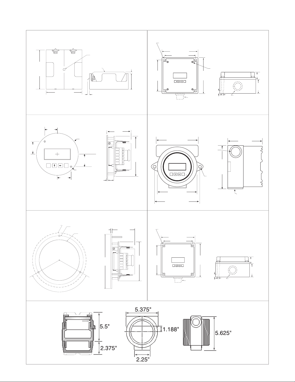
4.92
(125)
4.33
(110)
4.33 (110)
#8 Screw Mounting holes molded directly under cover
screws. Max. screw head .29" (Typ. 4 places)
E
M
.98
(25)
1.97
(50)
.18(5)
.43
(11)
BOTTOM VIEW
To access terminals, remove cover
and 4 panel screws. Terminals are
on bottom side of PC board.
Panel Screws
4.92(125)
TOP VIEW (PANEL INSTALLED)
Optional HF2, HF3
Hub Fitting
Optional H2, H3
Hub Holes
5.10
(130)
4.45
(113)
4.45 (113)
#8 Screw Mounting holes molded directly under cover
screws. Max. screw head .29" (Typ. 4 places)
E
M
1.1
(28)
1.97
(50)
.18(5)
BOTTOM VIEW
5.10(130)
TOP VIEW (PANEL INSTALLED)
Optional HF2, HF3
Hub Fitting
Optional H2, H3
Hub Holes
.36
(9.2)
To access terminals, remove cover.
Terminals are on bottom side of PC board.
4.63
(117)
3/4 NPT
(2) HLS
5.00
(127)
5/16
4.25
(108)
5.25
(133)
E
M
5.00
(127)
To access terminals, unscrew cover and loosen 2 panel screws.
Terminals are on bottom side of PC board.
Optional 3rd
Conduit Entry
3.062" (77.77)
Dia. Cutout
3.582" Dia. Bolt Circle
.125" Holes to be 120
° Apart
Outside Dotted Line Shows
Outside Panel Dimension
(4.00" Diameter)
120°
.10
(2.54)
4.00
(101.6)
1.7
(43)
2.875
(73)
Panel
Cutout
E
M
3.0120 DIAMETER
.900
(22.8)
.992
(25.2)
Mounting holes
.125 Drill (2 places)
.438 Nylon Spacer
Supplied
1.8
(46)
2.875
(73)
.10
(2.5)
.438
(11.1)
.900
(22.8)
.992
(25.2)
2.40
(61)
2.20 (56)
0.95 (24)
0.30 max. (7.6)
0.15 (3.8)
Battery
Mounting Hole
0.125 (3) dia.
BATPACK
5.5"
2.375"
5.375"
2.25"
5.625"
Additional conduit entries available upon request.
Additional conduit entries available upon request.
BATDT-M-2
BATDT-M-0
BATDT-M-1
BATDT-M-3
BATDT-M-5
BATDT-M-6
Page 8

THEORY OF OPERATION
TYPICAL APPLICATIONS
Remote
Reset Switch
12 VDC
Power
Supply
+
-
1 Mag Input 1
2 Mag Input 2
3 Shield/Common
4 Reset Input
5 Contact Input
6 Common/ DC In (-)
Turbine Meter with
Mag Pickup
6 5 4 3 2 1
MAG INPUT / DC POWERED
DC In (+) 12
Not Used (-) 11
Opto Input (+) 10
Opto Input (-) 9
Opto Out (+) 8
Opto Out (-) 7
789101112
KEP
115-12
or
Ext. Battery
(Power option
A
or B)
Flowmeter with
Switch Closure Output
DC In (+) 12
Not Used 11
Opto Input (+) 10
Opto Input (-) 9
Opto Out (+) 8
Opto Out (-) 7
1 Mag Input 1
2 Mag Input 2
3 Shield/Common
4 Reset Input
5 Contact Input
6 Common/ DC In (-)
6 5 4 3 2 1
CONTACT INPUT / PULSE OUTPUT / BATTERY POWERED
123456
789101112
(Power option
A
or B)
Remote
Reset Switch
1 Mag Input 1
2 Mag Input 2
3 Shield/Common
4 Reset Input
5 Contact Input
6 Common/ DC In (-)
Turbine Meter with
Mag Pickup
6 5 4 3 2 1
MAG INPUT / BATPACK POWERED
DC In (+) 12
Not Used(-) 11
Opto Input (+) 10
Opto Input (-) 9
Opto Out (+) 8
Opto Out (-) 7
789101112
BATPACK PLUGIN
CONNECTOR
BATPACK
(Power option
or B)
(Power option C or
AC)
Turbine Meter with
Mag Pickup
1 Mag Input 1
2 Mag Input 2
3 Shield/Common
4 Reset Input
5 Contact Input
6 Common
6 5 4 3 2 1
+
-
Strip Chart
Recorder
MAG INPUT / 4-20 mA LOOP POWERED
4-20mA (+)(+) 12
4-20mA (-) 11
Opto Input (+) 10
Opto Input (-) 9
Opto Out (+) 8
Opto Out (-) 7
789101112
24 VDC
Power
Supply
+
-
freely used so long as proper polarity is observed.
terminals (+) 12 and (-) 11. Accidental wiring to (+) 12 and (-)6 should be avoided since excessive current
fl ow may result with power option "C".
cidental connections to earth may result in erroneous operation of the analog output and/or excessive
current fl ow with power option "C".
eration of the analog output and/or excessive current fl ow with power option "C".
WIRING
A 10 point linearization table is used to construct a curve describing the relationship of K-Factor and input frequency.
The measured input frequency is used to access the table. A linear interpolation of adjacent point pairs is used to
arrive at the K-Factor at that input frequency. The fl ow rate and total are then computed based upon the K-Factor
for that measurement sample.
For best performance and resolution choose as many decimal places as possible in the K-Factor.
Example: Enter a K-Factor of 1 as 1.000.
otal
Sum of Input Pulses
C
C
x
Ti
Where
60 for rate per minute read out
3600 for rate per hour read out
86400 for rate per day read out
“D” option Only
The unit computes the rate for the analog output
Page 9

3
4
5
7
6
8
20
S
CTS
GND
G
T
5
4
3
1 ON
2 OFF
3 OFF
4 ON
5 OFF
Typical Hookup
18
17
16
15
14
13
18
17
16
15
14
13
BATDT-M
Unit
1
BA
TDT-M
Unit
2
Co
nnect 16 to 14
for optional
T
erminating Resistor
115 VAC
Model
115-24
24 VDC
Power Supply
(+)
(–)
G
+
T
T
+
Model
CA285
115 VAC
CA285
Po
wer Adaptor
PC with
RS-232 Port
Tx/Rx (-)
Tx/Rx (+)
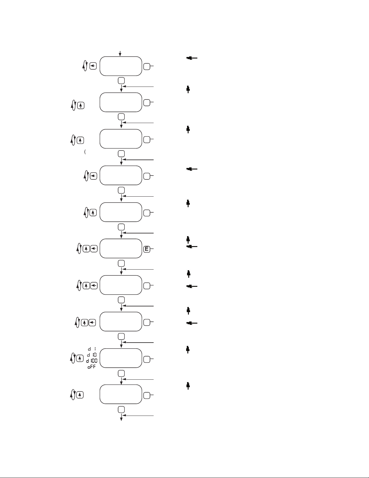
Page 10

6
DEFINITIONS
key while the unit is running to save the total value. The display will show
the battery(ies)
key to step to the next digit to the left. Press the
key to enter the 5 digit code. If the entered
code is correct, the display will advance to the next menu prompt (
to the run mode.
key to clear the grand total and return to the
key to skip and advance to the next menu selection.
of this decimal automatically limits the number of decimal locations allowable in the rate and total to acceptable
key to move the decimal. Press the
key to select the displayed decimal location.
For best performance and resolution choose as many decimal places as possible in the K-Factor.
Example: Enter a K-Factor of 1 as 1.000.
/
tion. The
linearization selection is recommended for fl ow meters whose K-factors change with different
fl ow rates. This selection allows users to enter up to 10 different frequencies with 10 corresponding K-factors for
different fl ow rates. The
setting is used for fl ow meters whose output is linear over its' entire operating
fl ow range. Press the
key to enter the displayed factor type.
/
yes set Pnts
for
to skip and keep the existing values.
for the fl ow sensor. The pulses/unit volume is implied by the totalizer descriptor when a descriptor is used. The
GAL pulses/gallon GAL pulses/gallon
LIT pulses/liter BBL pulses/BBL
FT3 pulses/ft3 MCF pulses/MCF
M3 pulses/M3 M3 pulses/M3
Factors from 0.0001 to 99999999 may be used. A "0" value for the factor is not allowed and the unit will default
to "1" in LSD if a "0" entry is attempted . The factor is displayed on the subsidiary (lower) display. Press the
key to step to the next digit to the left. Press the
key to enter the
displayed factor.
the 20 points (#). Press the
key to step to the next digit to the left.
key to enter the desired frequency for point #.
key to step to the next digit to the left. Press
the
key to enter the desired factor for point #.
The display will advance to the next point (Fr#) after each entry of the Fr & Fac until all 20 points are com-
Page 11

DEFINITIONS
and will scale the totalizer display accordingly. (i.e. if the tdec is set in the tenths position (1234567.8), 100 will be
displayed as 100.0). The location of the decimal point allows for greater resolution of both the totalizer display
and the pulse output. The pulse output advances at a rate dependent on the least signifi cant digit of the total-
of totalizer decimal locations allowable is reduced with each decimal place added to the factor decimal. Press
the
key to move the decimal. Press the
key to enter the displayed decimal location.
Note:
The selection of the factor decimal point limits the available selections for the number of decimal
tor. Press the
key to enter the selected descriptor.
option.) The scale setting is shown on the main (upper) display. Press the
key to enter the displayed scale setting.
A rate descriptor corresponding to the above choice will be illuminated on the display.
The ratemeter decimal is not a dummy decimal and will scale the rate display accordingly. (i.e. if the r decloc is
set in the tenths position (123.4), 100 will be displayed as 100.0). The ratemeter decimal location is restricted
to a maximum of 4 places (.1234). However, the number of ratemeter decimal locations allowable is reduced
with each decimal place added to the factor decimal. Press the
key to move the decimal. Press the
key
to enter the displayed decimal location.
NORMALIZING FACTOR - Normalizes (averages or dampens) the fl ow rate data being received. Enter a
value from 0 to 9. Higher settings provide more normalizing (averaging) for a more stable display. Derived
from the equation:
("NOR" + 1)
are not detected within this "window", the rate will be computed as 0 and the analog output will read 4mA.
The output will update once every second as long as the unit receives valid data within a second. Some inter-
key to step to
the next digit to the left. Press the
key to enter the displayed delay value.
output 4mA. Press the
key to step to the next digit to the left. Press
the
key to enter the displayed out lo value.
will output 20 mA. Press the
key to step to the next digit to the left.
key to enter the displayed out hi value.
Page 12

DEFINITIONS
the selected divider. The pulse out can be divided by 1 (
the divider set at 1, the unit will give a pulse out for every increment of the LSD displayed.
does not exceed the maximum rate of the pulse output. If the pulse output
sage “E PULSE”. Press the “E” key to return to the run mode.
or 0.0625 (8Hz). This menu item is skipped if
is turned off.
to gain access to the menu when the unit is locked. Press the
key
to step to the next digit to the left. Press the
key to enter the displayed code.
Record this number for later use! LOCK CODE:
____________________
key to enter
the displayed selection.
Page 13

The
prompt will only appear if
key to choose YES or NO.
to the menu.
key to increment each individual digit of the code.
key to increment each individual digit of the code.
key to advance to the next digit.
to run mode
key to step the factor decimal to the desired location.
to skip and keep the existing location
For best performance and resolution choose as many decimal places as
key to choose factor type (
or
key to increment each individual digit of the factor for point
#.
key to advance to the next digit.
key to increment each individual digit of the frequency for
key to advance to the next digit.
Frequency/factor point pairs must be entered in ascending order of fre-
quency
The
prompt will only appear if
ordered without the 10 point linearization option.
key to increment each individual digit of the factor.
key to increment each individual digit of the factor.
key to advance to the next digit.
CLR ToT
CLEAR
TO
ACT
OR
ACT
OR
ent Code
correct
ACT
OR
TYPE
lInear
lInear
selected
selected
#####
for POINT
(Fr0-Fr9)
ACT
OR for
(F
AC0-F
AC9)
0
9
SET pnts
No
SET
selected
No
selected
TOTAL
TOTAL
Page 14
key to step the totalizer decimal to the desired location.
key to step to the desired totalizer descriptor.
When option "D" (rate per day) is ordered; selections are:
GAL, BBL, MCF, M3, "blank"
key to step to the desired scale setting.
When option "D" (rate per day) is ordered; selections are:
min, HRS, days
key to step the ratemeter decimal to the desired location.
key to increment each individual digit of the delay.
key to increment each individual digit of the delay.
key to advance to the next digit.
key to increment each individual digit of the out low setting
This will only display on units with Analog Output.
key to advance to the next digit.
key to increment each individual digit of the out high setting
This will only display on units with Analog Output.
key to advance to the next digit.
key to step to the desired pulse scale divider for the pulse output.
key to step to the desired pulse width for the pulse output.
This will not display if Pulse Out is turned OFF.
key to increment each individual digit of the "nor" factor.
)
GAL
(BBL, MCF)
to
99.9
.5
Continue On
TOTAL DECIMAL
TOTAL
SCALE
OUT LOW
OUT HIGH
SCALER
Page 15

address
baudrate
parity
ADDRESS
ARITY
odd
even
4800
2400
stopbits
STOP BITS
(only shows if
parity = none)
vieuulog
TE
VIEW LOG
no
CODE
loC UnIt
TURN LOCK
ON or OFF
no
TE
(date
of
last
log)
T
Continued From Previous Page
to
247
2
0.0
to
0101.2000
to
00.00
to
23.59
00.00
to
23.59
yes
YES
selected
No
selected
key to increment each individual digit of the address.
key to increment each individual digit of the address.
key to advance to the next digit.
key to select the desired baud rate.
key to select the desired parity.
key to select the desired number of stop bits.
key to increment each individual digit of the trans. delay.
key to increment each individual digit of the trans. delay.
key to advance to the next digit.
key to increment each individual digit of the date.
key to increment each individual digit of the date.
key to advance to the next digit.
key to increment each individual digit of the time.
key to increment each individual digit of the time.
key to advance to the next digit.
key to increment each individual digit of the log time.
key to increment each individual digit of the log time.
key to advance to the next digit.
key and select "yes" to view log. Select "no" to skip.
The date of last log will be shown in the format (MM.DD) if "yes" was se-
or
to view previous logs and exit when the end of datalog is
key to step to the desired lock setting.
key to increment each individual digit of the lock code.
key to increment each individual digit of the lock code.
key to advance to the next digit.
key and select "yes" to clear log. Select "no" to skip.
Page 16

A suitable pulse producing device or fl ow meter is wired to one of the three pulse inputs provided on the BATDT-M.
terminals 5 and 6. Any high level, DC pulse type may be connected to terminals 9(-) and 10(+).
The fl ow totalizer is updated once per second* with battery power, 8 times per second with DC or loop power. If no
The fl ow total may be cleared by the front panel switch sequence or by a contact closure on the remote reset ter-
To reset the unit from the front panel, the following key sequence is required:
Enter the proper code to advance to the
prompt)
To clear the total. Unit will return to operation
The unit will measure the fl ow rate once every second* with battery power, 8 times per second with DC or loop
The analog output will be scaled based on the user selected zero and full scale and the measured fl ow rate. The
analog output is updated at the same time as the rate computation.
The pulse output updates at the same rate as the total display in accordance with the instrument setup of pulse
scaling.
* Slow input pulse rates, large delay setting and internal math operations may delay the update rate of information.
A faster update rate occurs when the unit is loop powered or externally powered.
1. See also setup mode for description of its operation
2. See also Calibration Section for description of its Operation
This is the magnetic reset area when option "RN"
and slide across the top of housing. The 5 digit total will
is used to (after verifi cation of the password) clear the total
& enter the setup menus
is used to force a Save of the total to fl ash memory prior to
is used to enable the user to view the datalog of daily total
Press once to be offered "View log?"
Press
to change “NO” to “YES”
Press either
or
to view up to 27 total readings from
30 seconds automatically if no keys are pressed
Page 17

The BATDT-M is provided with extensive self checking which assists the user in the location of setup entry errors
and in reporting malfunctions or unusual operating conditions. When an error occurs, the display will fl ash. Press
any key to see the error message corresponding to the error that has occurred. Press any key again to acknowl-
edge the error. (If the error can be eliminated by a change of setup values, the unit will automatically advance to
the MENU so that the appropriate setup changes can be made).
Table - 2 illustrates the warning message, problem, and recommended corrective actions.
WARNING MESSAGE CAUSE CORRECTIVE ACTION
Total rollover None required
Rate value for analog Set rate value for analog high
low set higher than rate greater than rate value for
value for analog high. analog low.
Computed rate Use lower rate dec point
exceeds 99999
Factor = 0 Enter a factor other than 0
Pulse out Overfl ow Use different pulse scaler or
totalizer decimal point
Save to fl ash Write down displayed total and
memory failed setup values if you are changing
the battery. If total wasn't saved,
it will display an arbitrary total
when new battery is installed. In
this case, reset the total to 0 and
check the setup information.
ANALOG OUTPUT CALIBRATION
the 4-20 mA has been accurately set to 4.000 and
20.000 mA by the factory. No calibrationshould be required.
The 4-20 mA output may be verifi ed periodically by installing a digital milliamp meter(DMM) in series with the
analog output and simulating a full scale or over range fl ow rate.
with a power supply (8.5 to 30 volts DC) to TB12 (+) and TB11 (–). The output should read 4.000 ma (± 0.005).
down until the output reads 20.000 ma (± 0.005). Press "E" and the unit will return to the "RUN" mode.
Page 18

This product (excluding batteries) is warranted
against defects in materials and workmanship
for a period of two (2) years from the date of
shipment to Buyer.
The Warranty is limited to repair or replace-
otherwise abused.
ALL OTHER WARRANTIES, EXPRESSED
Ordering Information
Series:
* 0 = OEM
*
2 = NEMA 4X Box (BATDT-M behind clear cover)
3 = Explosion Proof Housing
5 = NEMA 4X Box (BATDT-M outside opaque cover)
6 = Double Ended Explosion Proof Housing (consult factory)
* A = Battery (2 supplied)
B = External Power Supply (8.5 to 30 VDC)
C = Loop Powered with 4-20 mA Output
AC = Loop Powered with 4-20 mA Output
and 2 Batteries
Options
(Multiple Options Available)
S1 = Serial Setup Software for use with BSAC1
S2 = RS485/Modbus/Data Logger - Isolated (power options B
and C only)
4 = 20 Point Linearization (10 point with S2 option)
D = Rate per Day , Hour or Minute
ET = Extended Temp.: -22°F to 158°F (-30°C to 70°C)
CE** = CE Compliant
CSA** = CSA Listed Explosion Proof
IS** = UL Listed IS (planned)
TRX = NEMA7 Explosion Proof Reset Switch
(mounting style 3 only)
RN = External Magnetic Reset
T = Third Conduit Entry in Ex-Proof Housing (mounting style 3 )
H2 = 0.875" Hole for mounting styles 2 and 5
HF2 = 0.5" Female NPT Hub fi tting for mounting styles 2 and 5
H3 = 1.125" Hole for mounting styles 2 and 5
HF3 = 0.75" Female NPT Hub fi tting for mounting styles 2 and 5
Accessories:
equal
* External battery pack supplied with models BATDT-M0A & BATDT-
** Contact factory for latest information
Page 19

Apendix A: Modbus RTU Protocol
When the BATDT-Millennium is equipped with the Modbus option, the protocol it uses is the Modbus RTU pro-
tocol. This protocol defi nes a message structure that hosts and clients will recognize and use on the Modbus
access to another device (BATDT-Millennium), how it will respond to requests from the other devices, and how
errors will be
detected and reported. It establishes a common format for the layout and contents of message fi elds. During
communications on a Modbus RTU network, the protocol determines how each BATDT-Millennium will know its
device address, recognize a message addressed to it, determine the kind of action to be taken, and extract any
data or other information contained in the message. If a reply is required, the BATDT-Millennium will construct the
The BATDT-Millennium with Modbus communications option supports the Modbus RTU (Remote Terminal Unit)
character density allows better data throughput than ASCII for the same baud rate. The Modbus RTU uses a Mas-
ter-Slave Query-Response Cycle in which the BATDT-Millennium is the slave device.
The BATDT-Millennium with Modbus communications option supports the following function codes:
01 Read Coil Status Reads the status of a coil (ON or OFF)
03 Read Holding Registers Reads the value in a holding register
05 Force Single Coil Forces a single coil (0x reference) to either ON or OFF
06 Preset Single Register Presets a value into a single holding register (4x reference)
15 Force Multiple Coil Forces each coil (0x reference) in a sequence of coils to either ON or
16 Preset Multiple Registers Presets values into a sequence of holding registers (4x reference)
The setup menu allows Modbus RTU Protocol communications parameters of: Device ID, Baud Rate, and Par-
Page 20

(each register is 2 bytes)
Access
Volume Flow Reg 40001 & 40002 Float Read
Total Reg 40003 & 40004 Float Read
Analog Out Low Reg 40049 & 40050 Float Read/Write
Analog Out High Reg 40051 & 40052 Float Read/Write
Page 21

Access
Total Decimal Point Reg 40135 Integer Read/Write
*Total Descriptors Reg 40136 Integer Read/Write
*Rate Time scale Reg 40137 Integer Read/Write
The Float data type follows the IEEE format for a 32 bit fl oat.
* Total Descriptor and Rate Time Scale Descriptor
Total Descrptor
Total Descrptor
Value
GAL 0
FT3 2
M3 3
Descrptor
Descrptor
Value
/SEC 0
/MIN 1
/HR 2
/DAY 3
The above values can be used to set the descriptors through the Modbus protocol.
(each coil is 1 bit)
Access
Total Reset Coil 00005 bit Write
(continued)
 Loading...