

Page 1

BATCHtrol II
Software Versions 8.x & 12.x
Installation and Operating Manual
Description
The Batcher is a programmable, microprocessor based unit which provides batch control, monitors ow
rate and controls the ow of processing liquids. Start/Stop controls can be used in conjunction with prewarn and nal relays to provide valve actuation or pump control. An optional conguration offers streamlined preset adjustments, remote Start, Stop & Reset, and weighted averaging.
Features
❑ Pulse or Analog Input
❑ Display Batch, Rate or Grand Total
❑ Pulse Count Input up to 20 KHz
❑ 16 Point Linearization
❑ 8 Digit K-Factors for Rate and Total
❑ Security Lockout
❑ 2-Way RS232/422 Communications
❑ NEMA 4X/IP65 Front Panel
❑ Scalable 4-20 mA Output
❑ Scaled Pulse Output
❑ Optional Conguration Includes:
- Streamlined Preset Adjustment (Easy Preset)
- Remote Start, Stop and Reset
- Weighted Averaging
Kessler-Ellis Products Co.
BATCHtrol II
Application
The unit is normally used for batch control or inventory tracking. The display may be toggled between
batch, rate, and grand total. A programmable K-factor makes keying-in engineering units easy. The unit
accepts pulse, contact closures or analog inputs and provides two separate preset controls.
Principle of Operation
The batcher receives an input from a pulse producing owmeter through a sensor. The user programs
the batcher to condition the incoming pulses signal and compute the batch ow and ow rate. A wide
variety of different functions can then be performed based on the programmed congurations such as
start/stop functions, totalizing, and/or ow rate monitoring. Several other inputs, outputs and functions are
available.
99392 05/21/08
BATCHtrol II Series Technical Manual
Page 2

!
SAFETY INSTRUCTIONS
The following instructions must be observed.
• This instrument was designed and is checked in accordance with
regulations in force EN 60950 (“Safety of information technology
equipment, including electrical business equipment”).
A hazardous situation may occur if this instrument is not used for
its intended purpose or is used incorrectly. Please note operating
instructions provided in this manual.
• The instrument must be installed, operated and maintained by
personnel who have been properly trained. Personnel must read
and understand this manual prior to installation and operation of the
instrument.
• The manufacturer assumes no liability for damage caused by incorrect
use of the instrument or for modications or changes made to the
instrument.
Technical Improvements
• The manufacturer reserves the right to modify technical data without
prior notice.
Page 3

CONTENTS
1. INTRODUCTION
1-1 General Description ..................................................................................................1
1-2 Typical Application ....................................................................................................1
1-3 Principles of Operation .............................................................................................1
1-4 STD PRE and EZ PRE Operation Modes ................................................................3
1-5 Specications ...........................................................................................................4
1-6 Dimensions ...............................................................................................................5
2. INSTALLATION
2-1 Receipt of Equipment ...............................................................................................6
2-2 Return Shipment.......................................................................................................6
2-3 Panel Mounting.........................................................................................................6
2-4 Electrical Connections ..............................................................................................6
2-5 Wiring Connections and Diagrams ...........................................................................7
3. OPERATION
3-1 Front Panel Operation ..............................................................................................8
3-2 VER 8.7 Programming..............................................................................................9
3-3 VER 8.7 K-Factor Programming ...............................................................................9
3-4 Software Version 8.7 Programming Flow Chart .....................................................10
3-5 VER 12.0 Programming..........................................................................................11
3-6 VER 12.0 16 Point Linearization Notes .................................................................. 11
3-7 Software Version 12.0 16 Pt. Programming Flow Chart .........................................12
3-8 How to Program......................................................................................................13
3-9 Frequently Asked Questions About Setting Up The Batcher ..................................13
3-10 Setup Procedure For The Batcher ........................................................................14
3-11 Run Mode .............................................................................................................27
3-12 Internal Operation .................................................................................................29
4. INPUTS
4-1 Digital Pulse Inputs .................................................................................................30
4-2 Analog Inputs ..........................................................................................................30
4-3 DC Power Inputs ....................................................................................................32
4-4 AC Power Inputs .....................................................................................................32
5. OUTPUTS
5-1 Frequency Output ...................................................................................................32
5-2 Control Outputs ......................................................................................................33
5-3 Optional Analog Output ..........................................................................................33
5-4 Optional RS232 / RS422 Serial Communications ..................................................34
Page 4

CONTENTS
6. TROUBLE SHOOTING AND MAINTENANCE GUIDE
6-1 Warning Messages .................................................................................................34
6-2 Troubleshooting ......................................................................................................35
6-3 Removing The Case ...............................................................................................36
6-4 Maintenance ...........................................................................................................36
7. CALCULATING THE K FACTORS
7-1 General ...................................................................................................................36
7-2 Calculating the K Factors .......................................................................................37
7-3 Calculating 16 Point K Factors ...............................................................................39
8. SERIAL COMMUNICATIONS
8-1 Unit Code................................................................................................................40
8-2 Baud Rate...............................................................................................................40
8-3 Parity ......................................................................................................................40
8-4 RS232 Electrical Requirements..............................................................................40
8-5 RS232 Card Wiring.................................................................................................41
8-6 RS422 Electrical Requirements..............................................................................41
8-7 RS422 Card Wiring.................................................................................................42
8-8 Strobe Input Electrical Requirements .....................................................................42
8-9 Strobe Wiring ..........................................................................................................43
8-10 Serial Interface Operation.....................................................................................43
8-11 Strobe Address Operation ....................................................................................45
9. Programming Worksheet
.................................................................................................46
Page 5
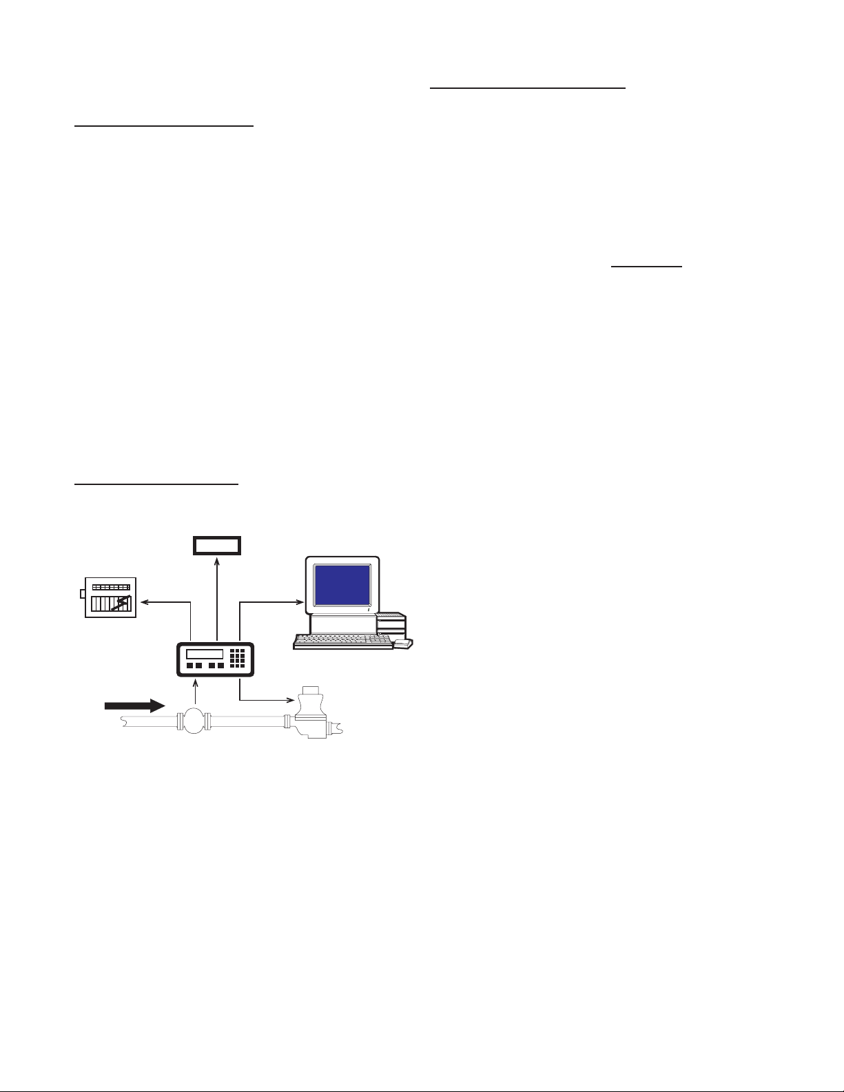
SECTION 1 INTRODUCTION
123456
Flowmeter
Computer
Solenoid Valve
Remote
Totalizer
Strip Chart
Recorder
Pulse Output
RS232
Output
Analog
Output
1-1 General Description
Sections 1 through 8 of this manual describe
the wiring, programming and functionality of
the standard Batch controller. Section 9 describes the wiring, programming and functionality of Batch controllers with software version
8.7 (Option 6). Software version 8.7 incorporates Remote Start, Stop & Reset with EZ
PRE (easy preset). EZ PRE is a useful tool
for applications that require frequent changes
to the Preset amount.
1-3 Principles of Operation
Presets
When the start button is pushed, two relays
engage simultaneously to start ow. When
the prewarn number is reached, one relay drops out. When the preset number is
reached, the other relay drops out. The user
may enter the two numbers when setting up
the batch counter. The prewarn is set a certain number of counts less than the preset
number. If the prewarn is set larger than the
preset, the message “PREWRONG” will appear on the display.
The Batch controller uses the following software versions:
VER 8.7 (Basic unit; Remote Start, Stop
& Reset with EZ PRE “Easy
Preset”)
VER 12.0 (Option 4; 16 point linearization)
1-2 Typical Application
The above application involves liquid ow.
The start button is pushed and the Batcher
receives pulses from the owmeter. The pulses are scaled by the K Factor and sent out via
the pulsed output to an external counter. The
Analog output is directed to a strip chart recorder which gives a hardcopy of the rate. As
the Prewarn is reached, the control valve par-
tially closes. When the nal Preset is reached
the valve shuts down completely. At any time
the ow can be suspended by hitting the stop
button. Through the serial communications, a
computer keeps a record of the daily events.
Ratemeter
Accurate to 5 1/2 digits (±1 display digit).
The ratemeter can be programmed to accept almost any number of pulses per unit of
measurement, sample from 2 to 24 seconds
maximum, and auto range up to 6 digits of
signicant information. The ratemeter with a
K Factor of 1 displays the rate of pulses per
second. Simply dial in the proper K Factor
to display in minutes, hours or other units of
measurement. Press the C button, while the
unit is displaying the batch, to display the rate;
‘R’ is displayed on the left side of the display.
K Factor
The K Factor is used to convert the input pulses or analog input into workable units. The
8 digit K Factor is a divider with a range of
0.00011 to 99999999 (the decimal point may
be keyed into any position). Separate K Factors may be entered into the count and rate
sections of the Batcher. Thus, you may batch
in gallons and display rate in liters per hour.
The maximum factored count speed is 20000
Hz. The maximum factored rate is 7 digits.
16 Point Linearization (Optional)
This option extends the accurate range by allowing users to dial in different K Factors for
different input rates. This option may be used
with digital or analog inputs. (See Section
7-3.)
1
Page 6

1-3 Principles of Operation (continued)
Counter
The maximum count is 99999999. In the
setup mode choose “RO” (Reset to Zero) for
adding (count up) operation or “SP” (Set to
Preset) for subtracting (count down) operation. At any time, the display can be made
to ash the Grand Total by pressing the ENT
button while in the run mode. Activating the
CLR button while the Grand Total is ashing,
resets the Grand Total counter.
Lockout
Unauthorized front panel changes can be prevented by entering a user selected, four digit
code, in the “Lockout” mode. The status of
the unit can be observed but “LOCK ON” appears if changes are attempted. Entering the
code again returns the unit to “LOCK OFF”
status.
Analog Output (Optional)
The Analog Output option is available on all
units except those with Square Law inputs.
Controlled by an Open Collector transistor, it
gives a 4 to 20mA (or 0-20mA) output which
corresponds to predened rate or total readings. In the Setup mode the user is prompted
to set the low and high (4 to 20 mA) values
and also decide if the analog signal will correspond to the ratemeter or totalizer.
Frequency out
The Batcher generates a pulse out for each
factored count. An NPN transistor output (Pin
2), can drive external devices at rates of 10,
200, 2000 or 20000 counts per second as
selected through the keypad menu. If the K
Factor scaled inputs generate pulses faster
than the output speed selected, an internal
buffer will store up to 9,999 counts before
“DATALOST” ashes on the screen. This indicates that the counts being totaled and the
scaled outputs may be incorrect. Note that
all counts stored in the internal buffer will be
pulsed out at the selected frequency even if
the counter is reset.
Outcard (Optional)
RS232 or RS422 serial two way communications are available. Up to 15 units can be
linked together in parallel and addressed
separately to transmit unit status or accept
new set points in the standard ASCII format.
Baud rates of 300, 600, 1200, 2400, 4800 or
9600 as well as choice of odd, even, space,
or mark parity can be selected by keypad control.
A sinking driver generates a linear current
across the user’s external device (such as a
strip chart recorder, PLC, computer, external
meter, etc). The Batcher can supply the 24
VDC to power the current loop. (Connect pin
15 to 13, Pin 16 is now +24 VDC with respect
to pin 12.) Connect Pin 16 to the + DC side of
the external device and connect Pin 3 to -DC
side of the external device.
2
Page 7

1-4 STD PRE and EZ PRE Operation Modes
STD PRE and EZ PRE Operation Modes
Version 8.7 of the batcher software allows the user to choose between STD PRE (Standard Preset)
and EZ PRE (Easy Preset) operation modes. STD PRE operation is well suited for batch amounts
that do not change, since the program mode must be entered to change the preset and the batch
count must be cleared before starting a new batch. EZ PRE has been designed for users who
frequently change the batch amount. During EZ PRE operation, the preset can be viewed and
changed without entering the program mode and another batch can be started without resetting the
unit.
Note: Before a batch is started and after a batch is complete, the unit will continue to totalize all
inputs.
Note: EZ PRE is not available on units with 16 Point Linearization.
Using STD PRE
Programming
Select STD PRE - Go into the Program Mode and
select STD PRE in the PRE TYP sub menu.
Set the PRESET and PREWARN - Go into the
Program Mode and enter the desired values for
the PRESET and the PREWARN.
Program the Counter - Go into the Program
Mode and set up the counter in the COUNT sub
menu.
Operation
Start a Batch - In the Run Mode, reset the total by
pressing “CLR”, then press “A” to start. When
started, both relays energize and the counter
begins to count. When the batch is complete,
the relays drop out and the unit displays the
amount that was batched (0 if in Set to Preset
mode).
Stop a Batch - Press “B”, to temporarily stop
process by de-energizing the PRESET and
PREWARN relays. Press start, “A”, to continue
process.
Repeat a Batch - In the Run Mode, reset the total
and press the start button.
Change the Batch Size - Go to the Program
Mode and enter new PRESET and PREWARN
values.
Using EZ PRE
Programming
Select EZ PRE - Go into the Program Mode and
select EZ PRE in the PRE TYP sub menu.
Set the PRESET and PREWARN - Go into the
Program Mode and enter the desired values
for the PRESET and the PREWARN.
Program the Counter - Go into the Program
Mode and set up the counter in the COUNT
sub menu.
Operation
Start a Batch - In the Run Mode, press “A” to
start. When started, both relays energize and
the counter begins to total. When complete,
the relays drop out and the display ashes the
current PRESET value.
Stop a Batch - Press “B”, to temporarily stop
process by de-energizing the PRESET and
PREWARN relays. Press start, “A”, to continue
process.
Repeat a Batch - Press the start button.
Change the Batch Size - With the current
PRESET ashing on the display, type a
new number using the keypad. This number
becomes the PRESET.
Display Batch Total or Rate - With the current
PRESET ashing, press “ENT” to place the
PRESET value in memory and use the “C”
button to toggle between the Batch Total and
the Rate.
3
Page 8

1-5 Specications
Housing:
High impact plastic case with NEMA 4X front
panel.
Dimensions:
See Section 1-5, Page 4.
Display:
8 Digit, 0.55” High, 15 Segment, Red Orange,
LED.
Input Power:
A: 110 VAC ± 15% or 12 to 27 VDC
B: 220 VAC ± 15% or 12 to 27 VDC
NOTE: AC Inputs are internally fused with a
160mA slow blow fuse.
Current:
Maximum 280 mA DC or 5.3 VA at rated AC
voltage.
Output Power:
(On AC powered units only): +12 VDC at 100
mA. Separate Isolated 12 VDC at 100 mA to
allow ± 12 VDC or +24 VDC, regulated ± 5%
worst case.
Temperature:
Operating: +32°F (0° C) to +130 ° F (+54° C)
Storage: -40°F (-40° C) to +200 ° F (+93° C)
(Extended operating temperature range
available, consult factory)
Memory:
EEPROM stores all program, display mode
and count data for a minimum of 10 years if
power is lost.
Reset
Front push button: “CLR” resets displayed
number and control output.
Remote Input (Terminal 5): Open or 0 to 1
VDC (low), 3 to 30 VDC (high), 10K ohm input
impedance to ground. Minimum pulse on /
off time 5 msec.
Accuracy over full temperature range:
Analog - Zero error: ±0.175% full scale max.
Overall error: ±0.5% full scale max.
Digital - 100% (within specied voltage
ranges)
Pulse Inputs:
3A: Standard. High impedance pulse input.
Open or 0 to 1 VDC (low), 3 to 30 VDC (high),
10K ohm input impedance. 20 KHz maximum
speed (min. on / off 25 usec).
3B: Same as 3A except 4.7 K ohm pull up resistor to +5 VDC with respect to Terminal 12.
Analog Inputs:
The current or voltage input is converted to a
highly linear 0 to 10 KHz frequency. This frequency can then be scaled by 8 digit K-factors
to display rate or count in the appropriate engineering units.
5A: 4-20 mA; 250 Ω input impedance.
5B: 0-20 mA; 250 Ω input impedance.
5C: 1-5 VDC; 15 KΩ input impedance.
5D: 0-5 VDC; 15 KΩ input impedance.
5E: 0-10 VDC; 15 KΩ input imped-
ance.
6A: Square Law: 4-20 mA; 250 Ω in-
put impedance.
4
Page 9
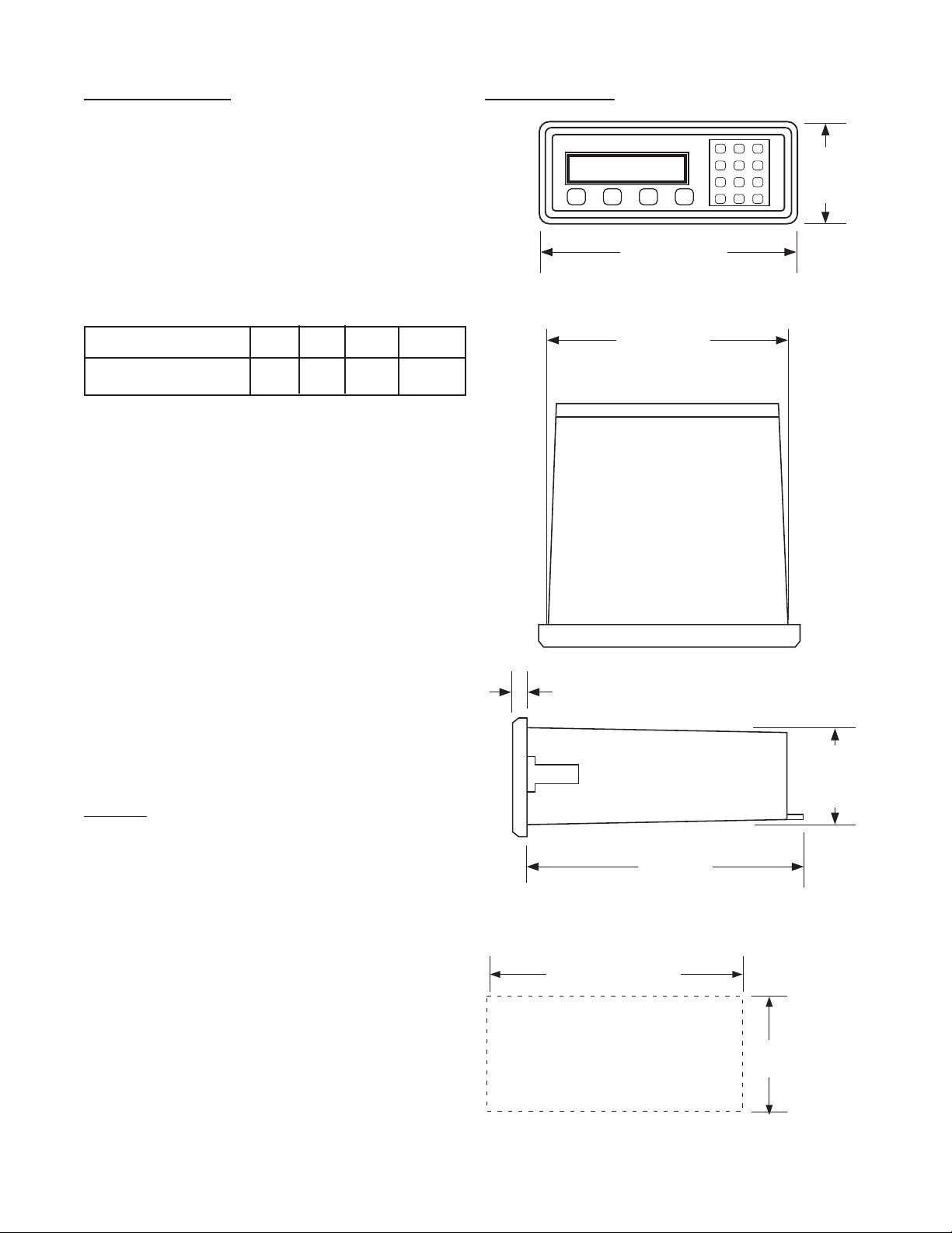
1-5 Specications (continued)
PANEL
CUTOUT
2.50 -0, +0.02
(63.5 -0, +0.5)
7.375 -0, +0.04
(187.3 -0, +1)
7.375
(187.3)
(NOM.)
0.53
(13.5)
6.0
(152.4)
2.48
(63)
(NOM.)
(NOM.)
A B C D
1 2 3
4 5 6
7 8 9
CLR0SET
8.17
(207.5)
3.31
(84)
Factored Output:
One pulse per each factored count
Sinking (NPN Transistor)
Open Collector sinks 250 mA maximum to 1
volt maximum from 30 VDC maximum
Internal buffer: 9999 pulses
Output speed: user selectable (see table
below)
Speed (Hz) 10 200 2000 20000
Min. on/off (msec) 47.5 2.0 0.2 0.013
Analog output:
(Not available with 4-20 mA, Square Law
input type)
4-20 mA (or 0-20 mA)
Sinking, (NPN transistor), Open Collector
Compliance voltage: 3-24 VDC, non-inductive
Accuracy: ±100 uA worst case
Update Rate: Follows ratemeter
1-6 Dimensions
Control Outputs:
SPDT Relays
Contact rating: 10 A 120/240 VAC or 28 VDC.
NPN Transistor Output
Open Collector sinks maximum of 100 mA from
10 VDC when active
Note: 10 VDC is provided at transistor outputs
through the relay coils. If current greater than
2 mA is drawn, the relay will remain energized.
Applying greater than 10 VDC may destroy the
unit. The transistor will sink 100 mA in the “ON”
state with relays installed.
All Dimensions in inches (mm)
5
Page 10

1-5 Dimensions (continued)
SECTION 2 INSTALLATION
2-1 Receipt of Equipment
When the equipment is received, the outside
packing case should be checked for damage
incurred during shipment. If the packing case
is damaged, the local carrier should be notied
at once regarding his liability. A report should
be submitted to the factory.
Carefully remove the equipment from the packing case and inspect for damaged or missing
parts.
2-2 Return Shipment
Do not return assembly or part with out a Return
Material Authorization. The RMA is obtained by
calling your local distributor.
2-3 Panel Mounting
The controller should be located in an area with
a clean, dry atmosphere which is relatively free
of shock and vibration. The Batcher is installed
in a 7.365” (187 mm) wide by 2.495” (63.4 mm)
high panel cutout. To mount the controller proceed as follows:
a. Prepare the panel opening.
b. Slip the gasket (provided) over the rear of
the counter case and slide it forward until it
engages the inner surface of the front bezel.
c. Install the screws (provided) in the mounting
brackets and insert in the holes located on
both sides of the Batcher.
d. Tighten the screws rmly to attach the coun-
ter bezel to the panel.
Full Size Panel Cutout Template
(copy before using)
2-4 Electrical Connections (Reference Figures
2-1 to 2-3)
All connections are completed at terminal blocks
located at the rear of the case. Make sure all
power is disconnected before making any electrical connections. In cases where cables are
situated in areas with heavy electrical elds,
6
Page 11
2-4 Electrical Connections (continued)
FLOWMETER
SHIELD
GROUND
SIGNAL
1
2
3
TB1
AMPLIFIER
TB2
3
2
1
4 - Input A
12 - Ground (-DC)
13 - +12 Volts Out
15 - Isolate -12 Volts
16 - Isolate +12 Volts
17 - AC In
18 - AC In
+24VDC
GROUND
1 10 VA C
60/50 Hz
!
FLOWMETER
ANALOG SIGNAL
4 - Input A
12 - Ground (-DC)
13 - +12 Volts Out
15 - Isolate -12 Volts
16 - Isolate +12 Volts
17 - AC In
18 - AC In
+24VDC
1 10 VA C
60/50 Hz
4 - Input A
12 - Ground (-DC)
13 - +12 Volts Out
15 - Isolate -12 Volts
16 - Isolate +12 Volts
17 - AC In
18 - AC In
1 10 VA C
60/50 Hz
Switch
Closure
NPN
Output
4 - Input A
12 - Ground (-DC)
13 - +12 Volts Out
15 - Isolate -12 Volts
16 - Isolate +12 Volts
17 - AC In
18 - AC In
1 10 VA C
60/50 Hz
Switch
Closure
PNP
Output
shielding is required for maximum noise immunity. One end of the shielding should be
connected to earth ground. Relays or inductive coils connected to or located in the immediate area should be arc suppressed with
appropriate diodes, MOV’s or resistor capacitor networks.
Caution:
An external fuse is required
for DC powered units.
DC Power: Use a 0.5 Amp
Fuse inline with Term. 14
AC units are internally fused.
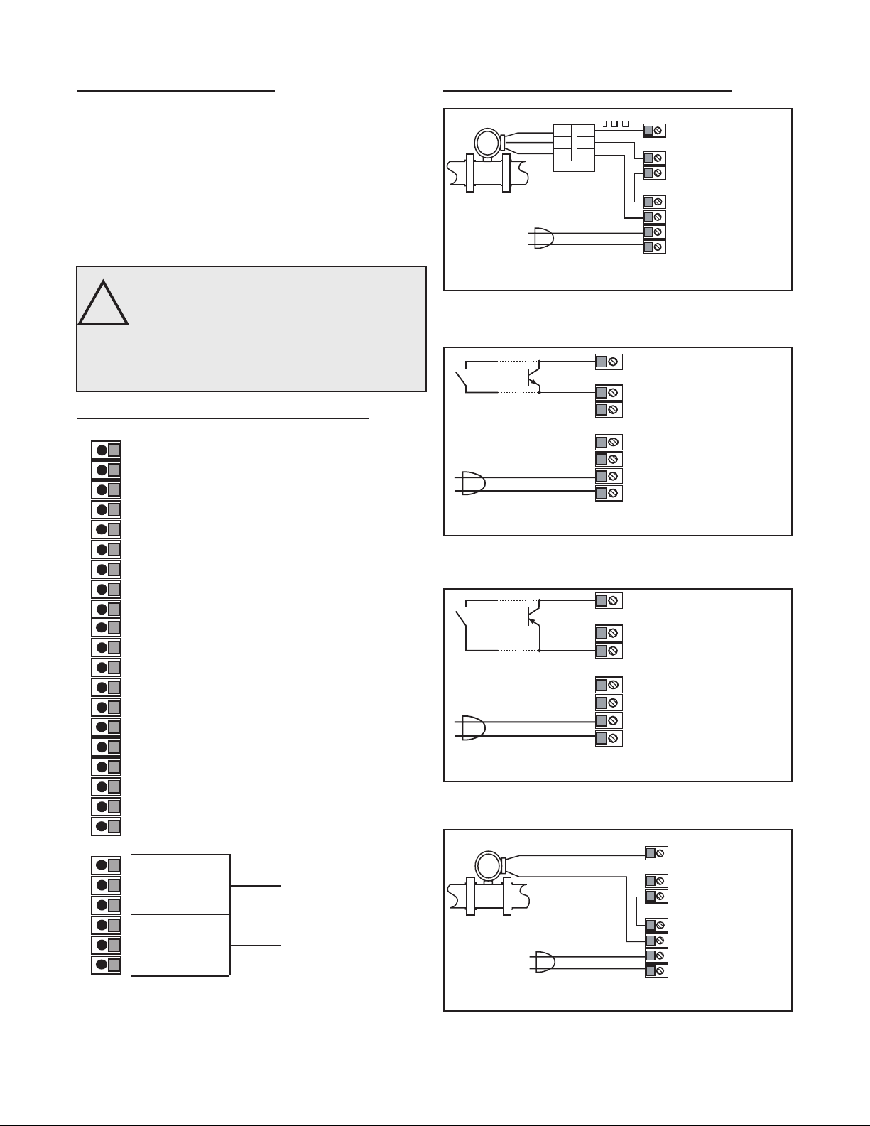
2-5 Wiring Connections and Diagrams
1 - Not Used
2 - Scaled Pulse Output O.C.
3 - Analog Output
4 - Input A (Pulse/Analog)
5 - Remote Stop/Reset Input
6 - Not Used
7 - Not Used
8 - Not Used
9 - Not Used
10 - Remote Start Input
11 - Ground (-DC), Input Common
12 - Ground (-DC), Input Common
13 - +12 Volts Out
14 - DC Power In (12 - 27 VDC)
15 - Isolate -12 Volts
16 - Isolate +12 Volts
17 - AC In
18 - AC In
19-Prewarn Transistor O.C.
20-Preset Transistor O.C.
2-5 Wiring Connections and Diagrams
All AC powered BT2 Models are equipped with an internal fuse.
Use KEP part #14039 for replacement
Figure 2-2
Typical Digital Wiring Connections
All AC powered BT2 Models are equipped with an internal fuse.
Use KEP part #14039 for replacement
Figure 2-3
Typical Digital NPN (Input 3B) Wiring
All AC powered BT2 Models are equipped with an internal fuse.
Use KEP part #14039 for replacement
Figure 2-4
Typical Digital PNP (Input 3A) Wiring
R1-N.O
R2-N.C. Preset
R3-Common
R4-N.O
R5-N.C. Prewarn
R6-Common
Figure 2-1 Terminal Block Connections
All AC powered BT2 Models are equipped with an internal fuse.
Use KEP part #14039 for replacement
Figure 2-5
Typical Analog Wiring Connections
7
Page 12
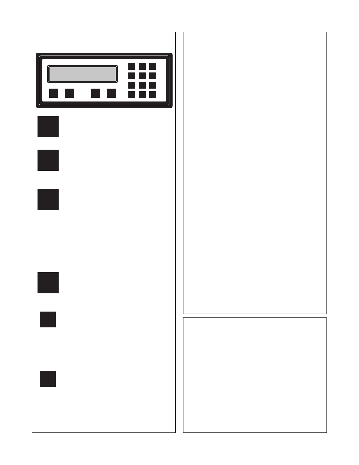
3-1 Front Panel Operation
STOP
D
START
RATE/TOTAL
MENU
CBA
ENT
0
7
4
1
2
3
6
5
8
9
CLR
START - Pressing “A”, starts the
A
process by energizing the PRESET and
PREWARN relays. Press “CLR” to reset
Batch Total before starting new batch.
Weighted Averaging
Version 8.7 of the batcher software includes
weighted averaging of the rate display. Weighted
averaging is not available on units with 16 Point
Linearization.
Weighted averaging can be used to create a more
stable display when the rate input is uctuating.
A weight, “W”, from 00 to 99 is applied to the old
rate data before the new rate data is sent to the
display. The following equation is used:
Rate Display =
W = Weight (00-99)
(Old Data x W + New Data)
(W + 1)
B
C
D
ENT
CLR
STOP - Pressing “B”, will temporarily
stop the process by de-energizing the
PRESET and PREWARN relays. Use
START to continue the process from
where it stopped.
RATE/TOTAL STD PRE mode
Pressing “C” toggles between rate and
total count displays. The rate display has
an “R” on the left side of the screen.
EZ PRE mode
Pressing “C” toggles between rate, total
count and preset displays in EZ PRE
mode. The rate display has an “R” on
the left side of the screen and the preset
display has a “P” on the left side of the
screen.
MENU - Pressing “D” takes the unit out of
the Run Mode and into the Programming
Mode (See Programming, Page 43 and
45). “D” is also used make to some
programming selections.
ENT - With Total Count showing in
the Run Mode (see “C” key), pressing
“ENT” displays the Grand Total, which
begins ashing on the screen. Press
“ENT” again to return to the Count. In
the Programming Mode, “ENT” is used
to accept a selection (See Programming,
Page 43 and 45).
CLR - When the count total is displayed,
pressing “CLR” will reset the counter to 0
or to Preset A depending on how it was
programmed. When the Grand Total is
displayed, pressing “CLR” will reset it to
0. When the Preset or Program Mode
values are displayed, pressing “CLR” will
reset them to 0, so that new values can
be entered.
If a weight of 00 is used, the new rate data will
go directly to the display without being averaged.
If a number other than 00 is entered for the
weight, then the new data will be averaged with
the old data before being sent to the display.
Higher weight numbers will create a more stable
rate display. Small rate changes will be more
noticeable when lower weight numbers are used.
Programming Weighted Averaging
1. In the Program Mode, got to the RATE sub menu
and program the K-FACTOR, the WINDOW, and
the SIG FIG parameters.
2. When the display shows WEIGHTXX (XX
represents the current WEIGHT value), either
accept the current value and return to the Run
Mode by pressing “ENT” or clear the current value
by pressing “CLR”.
3. If the current value was cleared, the display
shows WEIGHT00. Using the keypad, enter a
new WEIGHT value from 00 to 99. Press “ENT” to
accept the new value and return to the Run Mode.
Remote Start, Stop, and Reset
A 4 to 30 VDC positive pulse will activate these
inputs. Remote Start, Stop, and Reset is not
available on units ordered with the Control Input
option 7A (4-20 mA In, 4-20 mA Out).
START (Pin 10): When activated, the unit will
START as described in Front Panel Operation.
STOP/RESET (Pin 5): When activated, the unit will
STOP (If the unit is started and the batch is not
complete). A second pulse to pin 5 will reset the
counter (When the unit is stopped or when the
batch is complete). If pin 5 is held high (4 to 30
VDC), the display will ash “STOPPED” and any
start inputs will be inhibited.
8
Page 13

3-2 VER 8.8 Programming
Overview:
This Section of the manual provides an outline of
programming procedures for the batcher software
version 8.7. Detailed descriptions and programming
instructions for this unit are available in previous
sections of this manual. Page number references
are included to help you nd related information in
this manual.
Programming Procedures:
Enter Program Mode - Press the MENU button,
“D”, in the Run Mode.
Choosing a Sub Menu - Once in the Program
Mode, continue pressing the “D” button until the
desired Sub Menu is displayed. Press “ENT” to
enter the selected Sub Menu.
Making a Selection - An arrow, “↓”, appearing over
only the “D” button indicates that “D” is used to
change the selection. When an arrow appears
over “B” and “D”, one must be selected.
Entering a Value - The keypad is used to enter a
number. Use the “D” button to enter a decimal.
(Ex: 34.5 would be entered by pressing “3”, “4”,
“D”, and “5”)
Accept a Value or Selection - Press “ENT” to ac-
cept the value and go to next step.
Exit Program Mode - Program or skip each step
of one of the menus to return to the Run Mode.
Pressing “ENT” allows a step to be skipped without changing its value.
Key to Programming Flow Chart:
■
Display - This box represents the unit’s dis-
play. In the Run Mode, the ow rate, the batch
total, or the grand total will be displayed.
XX Current Value - The number that is currently
programmed for that step. It must be cleared
(CLR button) before entering a new value.
00 No Value - Indicates that programmed value
for that step has been cleared, and a new
number may be entered.
Keypad - Use the front panel keypad to enter
a value or select a decimal point location for
this step.
3-3 VER 8.8 K-Factor Programming
(See Programming Flow Chart, Page 10)
The average sensor K-Factor is usually provided in
pulses per unit volume, and will have to be modied
before entering it into the instrument. On most ow-
meters, the average sensor K-Factor is stamped
on the nameplate or provided on its documentation. (see section 7 for Calculating K-Factors, for a
complete example)
Count K-Factor:
The Count K-Factor must be modied to allow for
the decimal point location chosen in the ”DEC LOC“
step.
Sensor K-Factor
DPF
DPF - The Decimal Point Factor is a divider to compensate for the displayed decimal point.
DPF Table
DPF Decimal
1 XXXXXX.
10 XXXXX.X
100 XXXX.XX
1000 XXX.XXX
10000 XX.XXXX
100000 X.XXXXX
Rate K-Factor:
The Rate K-Factor must be determined to dis-
play the rate in the desired time unit. The oating
decimal point displayed by the Rate Meter oats
according to the signicant gure setting used in
the SIG FIG step.
Sensor K-Factor
Where:
TF - The Time Factor is a divider to adjust the
time units that the Rate Meter shows.
TF Table
TF Time Units Rate Display
1 Seconds Units per Second
60 Minutes Units per Minute
3600 Hours Units per Hour
86400 Days Units per Day
(For information on entering a K-Factor on a unit
with 16 Point Linearization, see 16 Point Linear-
ization Notes, page 11)
= Count K-Factor
= Rate K-Factor
TF
9
Page 14
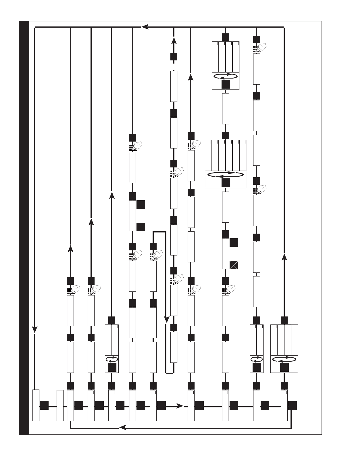
ENT
D
RATE
↓
D
ENT
K-FACTO R
XXXX
CLR
WINDOWXX
CLR
S I GF I G X X
CLR
WE IGHTXX
LOCKOUT
↓
ENT
D
SECUR XX
CLR
CODE
XXXX
CLR
UNIT X X
CLR
ALG OU T
↓
OUTFREQ
↓
ENT
D
ENT
D
D
ANLG RT↓ANLG CT
↓
ENT
SE T LO W
XXXX
CLR
SET HIGH
D
2000 ↓200
↓
ENT
20000
↓
10
↓
0
ENT
WINDOW00
ENT
S I G F I G 0 0
ENT
SECUR 00
ENT
0
UNIT 00
ENT
0
ENT
PL↓ SE R↓
ENT
D
B
⇒
BAUDRATE
D
1200↓ 2400
↓
600↓ 300
↓
4800↓ 9600
↓
COUNT
↓
ENT
D
K-FACTO R
XXXX
CLR
R0↓ SP↓
ENT
D
B
⇔
D.E.C. . .L.O.C.
8 7 6 54 3 2 1
ENT
0
ENT
PRESET
↓
ENT
D
XXXX
CLR
PREWARN
↓
D
XXXX
CLR
ENT
PRE TYP
↓
ENT
D
D
EZ PR E↓STD PRE
↓
ENT
0
ENT
0
ENT
MENU
D
Run Mode
◊ - On a Standard unit (Without 16 Point Linearization), the Count and/or the Rate must be programmed for basic operation.
§ - Sub menu will always appear, but feature may not be included in the unit. (Check Model Number).
Page
2, 24
§ Page
2, 23
§ Page 2, 21
Page 2, 19
◊ Page 1, 17
◊ Page 2, 15
Page 15
Page 1, 14
Page 1, 14
OUTCARD
↓
CLR
XXXX
CLR
WEIGHT0 0
ENT
ENT
0
ENT
ENT
PARITY
D
ODD↓ MARK
↓
ENT
EVEN
↓
SPA CE
↓
Software Version 8.8 Programming Flow Chart
10
Page 15

3-5 VER 12.0 Programming
(Unit with 16 Point Linearization)
Overview:
This Section of the manual provides an outline
of programming procedures for the software version 12.0. Detailed descriptions and programming
instructions for this unit are available in the following
sections of this manual. Page number references
are included to help you nd related information in
this manual.
3-6 VER 12.0 16 Point Linearization Notes
(See Programming Flow Chart, Page 12)
A K-Factor and a Frequency must be entered for at
least three points on a unit with Linearization.
Linearization K-Factor: The K-Factor for each
Linearization point must be modied to allow for the
display decimal point location chosen in the “DEC
LOC” step of the “DEV TYP” menu. Modify each
K-Factor using the following equation:
Programming Procedures:
Enter Program Mode - Press the MENU button,
“D”, in the Run Mode.
Choosing a Sub Menu - Once in the Program
Mode, continue pressing the “D” button until the
desired Sub Menu is displayed. Press “ENT” to
enter the selected Sub Menu.
Making a Selection - An arrow, “↓”, appearing over
only the “D” button indicates that “D” is used to
change the selection. When an arrow appears
over “B” and “D”, one must be selected.
Entering a Value - The keypad is used to enter a
number. Use the “D” button to enter a decimal.
(Ex: 34.5 would be entered by pressing “3”, “4”,
“D”, and “5”)
Accept a Value or Selection - Press “ENT” to ac-
cept the value and go to next step.
Exit Program Mode - Program or skip each step
of one of the menus to return to the Run Mode.
Pressing “ENT” allows a step to be skipped without changing its value. (Note: “B” or “D” must be
pressed on the rst step in the DEV TYP menu)
K-Factor
DPF
DPF - The Decimal Point Factor is a divider to
compensate for the displayed decimal point.
= Linearization K-Factor
DPF Table
Desired Total
Decimal Location: DPF
XXXXXX. 1
XXXXX.X 10
XXXX.XX 100
XXX.XXX 1000
XX.XXXX 10000
X.XXXXX 100000
Example: for X.X, DPF = 10
Calculating K-Factors and Frequencies: If a
Linearization table is not available, the K-Factor
and the frequency for each point can be calculated
using the Test Mode on the unit. Refer to Section
7-3.2, Test Mode Operation and K-Factor
Calculation, on page 37.
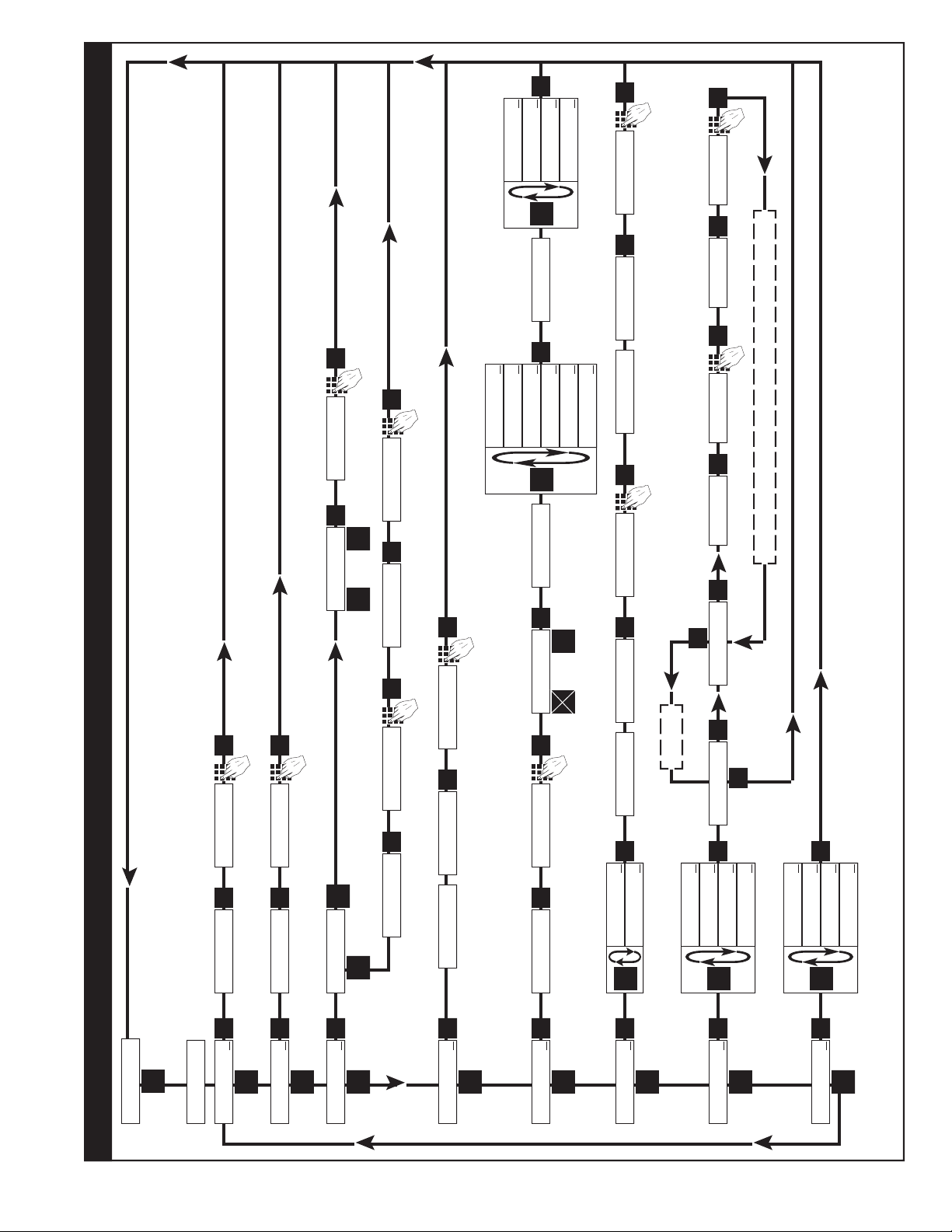
Key to Programming Flow Chart:
■
Display - This box represents the unit’s dis-
play. In the Run Mode, the ow rate, the batch
total, or the grand total will be displayed.
XX Current Value - The number that is currently
programmed for that step. It must be cleared
(CLR button) before entering a new value.
00 No Value - Indicates that programmed value
for that step has been cleared, and a new
number may be entered.
Keypad - Use the front panel keypad to enter
a value or select a decimal point location for
this step.
Entering K-Factors and Frequencies: Refer to
Section 7-3, Calculating 16 Point K-Factors, on
page 37 and the programming step listing on page
25.
11
Page 16
OUTCARD
↓
ENT
D
LOCKOUT
↓
ENT
D
UNIT X X
CLR
ALG OU T
↓
OUTFREQ
↓
ENT
D
ENT
D
D
ANLG RT↓ANLG CT
↓
ENT
SE T LO W
XXXX
CLR
SET HIGH
XXXX
CLR
D
2000 ↓200
↓
ENT
20000
↓
10
↓
UNIT 00
ENT
0
ENT
0
ENT
PL↓ SE R↓
ENT
D
B
BAUDRATE
D
1200↓ 2400
↓
ENT
600↓ 300
↓
4800↓ 9600
↓
PARITY
D
ODD↓ MARK
↓
ENT
EVEN
↓
SPA CE
↓
PRESET
↓
ENT
D
XXXX
CLR
PREWARN
↓
D
XXXX
CLR
ENT
DEV TYP
↓
ENT
D
0
ENT
0
ENT
MENU
D
Run Mode
Software Version 12.0 16 Point Linearization Programming Flow Chart
RT↓ CNT↓
R0↓ SP↓
ENT
D
B
D.E.C. . .L.O.C.
8 7 6 54 3 2 1
ENT
D
B
WINDOWXX
CLR
S I GF I G X X
CLR
WINDOW00
ENT
S I G F I G 0 0
ENT
16 POINT
↓
ENT
D
D
MINUTE S↓ HOURS
↓
ENT
SECONDS
↓
T EST
↓
POINT 00
1
POINT 01
ENT
F XX
CLR
F 00
ENT
K XX
CLR
K 00
ENT
ENT
CLR
To Exit
Increment to next point (Ex. POINT 02, POINT 03, Etc.
◊ - At least three points in the 16 Point Linearization sub menu must be programmed for basic operations.
Enter a Point # of “0” at any point to exit the 16 Point settupeep all data entered up to that point.
§ - Sub menu will always appear, but feature may not be included in the unit. (Check Model Number).
Do not use PL. Select SER.
CODE
XXXX
CLR
0
ENT
⇒
⇔
3-7
12
Page 17

3-8 How to Program
The initial programming of the unit is accom-
plished by rst depressing the MENU button.
After pressing the MENU button once, the
display will read preset. To cycle to the next
control parameter option, merely press the
MENU button and Prewarn will appear on the
display. If the user does not wish to choose
this section of the menu, depress MENU button again and the next control or parameter
will appear.
Selection of all MENU control parameters is
accomplished through the routine described
for Preset.
3-9 Frequently Asked Questions About
Setting Up The Batcher
Q. Is there any way to backspace if the wrong
button is hit by accident?
A. No, you can depress the CLR button and
start entering the number all over again or
press ENT repeatedly until back in the Run
mode and start over again from there.
Q. Is there any way to put a decimal point in a
number such as a preset or K Factor?
A. Yes, simply press the D button after the
digit that you would like the decimal point.
It will appear to the right of the digit.
The following is the sequence for entering a
Preset quantity.
1. Depress the Menu D button once. The
display will read MENU. After a one second pause the display will read PRESET.
2. Depress the Enter ENT button; the dis-
play will ash indicating that you are not in
the Run Mode and not displaying the current batch total.
3. If the batch size is satisfactory, depress
the ENT button. This value will be entered
into memory. Simultaneously, the unit will
return to the Run Mode.
4. To change the preset value, depress the
CLR button and enter new number. Example: Suppose “250” is the new batch
size. Press CLR, then 2 , then 5 , then 0 .
When the display holds the desired value,
depress the ENT button. The new batch
size will be stored in memory and simultaneously the batcher will return to the Run
Mode.
Q. Is there any way to enter a negative number
for one of the Presets or K Factors?
A. No, negative values are not allowed.
Q. Is there any way to ruin the unit or completely
erase it by entering a bad number?
A. No, if a number or entry is not valid the unit
will ignore it or ash an error message.
Q. If the unit does not have serial communica-
tions or analog out, does the OUTCARD and
ALG OUT sections of the menu still have to
be set up?
A. No, there are default settings from the fac-
tory already in the unit. No setup of these
menu items is necessary for normal operation.
Q. Does the Batcher have to be told what type
of input it has connected to it?
A. No, The input signals are conditioned in
hardware. This allows the input cards to
be interchanged without modifying the software.
Q. If CLR is not pressed, numbers can still be
written over the Presets or K Factors. Will
these numbers be accepted if the ENT button is pushed?
A. No, in order for a Preset or K Factor to be
changed, the old number must be cleared
out rst by depressing the CLR button.
13
Page 18

3-10 Setup Procedure For The Batcher
D
CLR
ENT
1 2 3 4
ENT
D
D
ENT
CLR
1 2 3 4
ENT
MENU ITEM 1 PRESET
PRESS DISPLAY
PRESET ↓
Menu Button.
Flashing PRESET number.
Enters Preset Routine.
0 Flashes.
Clears out existing PRESET.
1234 PRESET Flashes.
Sample Preset.
Last count, unit now in run mode.
Store new Preset.
Final Preset is Set.
MENU ITEM 2 PREWARN
The Prewarn value is the amount before the Preset value that the Prewarn relay will deactivate. For example, if
you want the Prewarn relay to drop out 10 counts before the Preset and your Preset is 1234, then set your Prewarn
at 10 (not at 1224). Enter a Prewarn of “0” for the Prewarn and Preset relays to activate together. To disable the
Prewarn relay, enter the same value for Preset and Prewarn.
PRESS DISPLAY
PRESET ↓
MENU Button.
PREWARN ↓
Flashing PREWARN number.
Enters Prewarn Routine.
0 Flashes.
Clears out existing PREWARN.
1234 Prewarn Flashes.
Sample Prewarn.
Last count, unit now in Run Mode.
The Prewarn is Set.
Note: Remember, if the prewarn is a larger number than the preset, then the warning “PREWRONG” will ash on
Store new Prewarn.
the display. Enter a prewarn value that is less than or equal to the preset to clear this warning.
14
Page 19

3-10 Setup Procedure For The Batcher (continued)
DDD
ENT
ENT
DDD
ENT
D
CLR
3 7 D 6
MENU ITEM 3 PRE TYP
This menu item is used to set up the Preset Type.
PRESS
DISPLAY
PRESET ↓
PREWARN ↓
PRE TYP ↓
STD PRE ↓ EZ PRE↓
Press D toggle between selections.
Enters displyed selection Run Mode
MENU ITEM 4 COUNT
Setting the Counter
PRESS
DISPLAY
PRESET ↓
The PRE TYP is Set.
PREWARN ↓
PRE TYP ↓
COUNT↓
K FACTOR
K FACTOR ashes then shows the current K Factor.
Note: The K Factor setup is skipped if the unit has 16 Point option. The unit goes directly to R0 SP.
0 Flashes.
Clears out existing K FACTOR.
37.6 Flashes.
Sample K Factor, or enter calculated value from notes or worksheet.
continued on next page
15
Page 20

3-10 Setup Procedure For The Batcher (continued)
ENT
B
B
B
B
D
ENT
ENT
MENU ITEM 4 COUNT (continued)
PRESS DISPLAY
R0 ↓ SP ↓
Store new K Factor.
RO is Reset to zero. SP is Reset to Preset. This selection determines whether the unit
counts up or counts down. If RO is selected ( B is pressed), the unit will count in the “up”
direction towards the Preset (dropping out the Prewarn, if passed). If SP is selected ( D
is pressed), the unit starts at the Preset and counts “down” towards zero (dropping out
the Prewarn at its set value.)
or Selects by moving the cursor under the
arrow by R0 or SP
DEC LOC
Store R0 or SP.
DEC LOC allows the user to choose where the decimal point will be located when
the Batch Count or Grand Total are displayed. The decimal point is for display only
and does not affect K Factors. (The K Factor must be scaled to reect the DEC LOC,
see Section 7 for calculating the K Factors) Simply press the keypad numbers to move
the decimal point. Only one decimal point can be displayed, multiple decimal points are
not available. Pressing 0 turns off the decimal point.
DEC LOC
As an example, the decimal point will move to the right of the fourth digit from the right
(displays units and thousandths).
Run Mode.
Store new DEC LOC.
The Counter portion of the Batcher is now set up.
16
Page 21

3-10 Setup Procedure For The Batcher (continued)
DDD
ENT
D
CLR
D
1 2 D 0 5 6
ENT
CLR
MENU ITEM 5 RATE
Setting the Ratemeter
PRESS
DISPLAY
PRESET ↓
PREWARN ↓
PRE TYP ↓
COUNT↓
RATE↓
K FACTOR
This selects the Ratemeter portion of the menu.
K FACTOR ashes then shows the current Ratemeter K Factor.
Note: The K Factor setup is skipped if the unit has 16 Point option. The unit goes directly to WINDOW.
0 Flashes.
Clears out existing K FACTOR.
12.056 Flashes.
Sample K Factor, or enter calculated value from notes or worksheet.
WINDOW ##
Store new K Factor.
Normally the ratemeter updates each second. If no signal comes in during that time, the
ratemeter will wait until the window times out or a signal comes in; the display will not update. The window is the maximum sample time, in seconds, on which the waiting period
is based. The range is from 02 to 24 seconds.
WINDOW 00
Clears out existing WINDOW number value.
WINDOW 05
As an example, extends the window to 5 seconds.
continued on next page
17
Page 22

3-10 Setup Procedure For The Batcher (continued)
CLR
ENT
ENT
CLR
ENT
MENU ITEM 6 RATE (continued from previous page)
From the previous page, we are in the SIG FIG setting portion of the Ratemeter setup Menu.
PRESS
DISPLAY
SIG FIG ##
Store new WINDOW.
SIG FIG indicates how many meaningful digits are shown. For example, if SIG FIG
is set at three; a rate of 24737.89 will be displayed as 24700; a rate of 0.739216 will be
displayed as 0.739. Note that trailing zeroes will be inserted only if necessary. Digits
beyond the SIG FIG value are truncated and zeroes are inserted as needed, no rounding is done.
SIG FIG 00
Clears out existing SIG FIG number value.
SIG FIG 04
As an example, display will show 4 signicant gures.
WEIGHT##
Store new SIG FIG.
WEIGHT is an averaging factor. Higher settings provide more averaging for a more
stable rate display. Derived from:
(OLD DATA • “WEIGHT” + NEW DATA)
(“WEIGHT + 1)
WEIGHT 00
Clears out existing WEIGHT value.
WEIGHT04
As an example,
RUN MODE
The Ratemeter portion of the Batcher is now setup.
18
Page 23

3-10 Setup Procedure For The Batcher (continued)
DDD
ENT
CLR
D
MENU ITEM 6 LOCKOUT
This menu item uses a 4 digit security code to prevent unwanted changes in the programming
or improper use of the Batcher. The unit is shipped from the factory with a security setting of
00 and a lockout code of 1000.
Security example: First set the security shut down time in the Lockout menu then go to the
Run Mode. Press the START button. The word STARTED should briey appear. If no signal
comes in before the security time is reached, the unit locks and displays SECURITY. Once the
unit locks all buttons except 0 thru 9 are disabled. To unlock the unit simply press in the lockout code. When the unit is unlocked all menu features are available for change.
Lockout example: To lock the unit, rst make sure it is in the Run Mode, then press 1 - 0 - 0 - 0.
The words LOCK ON should briey appear. Once the unit is locked:
a. Preset can still be accessed and changed.
b. Prewarn can still be accessed but cannot be changed.
c. the rest of the menu cannot be accessed.
To unlock the unit simply press 1 - 0 - 0 - 0. The words LOCK OFF will appear briey. When
the unit is unlocked all menu features are available for change.
To put in a different security time or lockout code follow this setup procedure.
PRESS
DISPLAY
PRESET ↓
PREWARN ↓
DEV TYP ↓
LOCKOUT ↓
SECUR ##
SECUR is the time, in seconds, that the unit will wait between pulses or for a
signal to come in once STARTED. For example: The SECUR is set at 15, in run
mode the START button is pressed. If at any time the unit does not receive a signal for
15 seconds the display will go to security and the unit will lock itself. The unit retains
elapsed security time if STOPPED before security times out. When restarted, the unit
resumes security timing from where it left off. As soon as a signal comes in the security
time is reset. Entering a security time of 00 disables the security feature.
SECUR 00
Clears out existing security time.
SECUR 34
As an example, unit waits 34 seconds before Security Mode.
Continued on next page
19
Page 24

3-10 Setup Procedure For The Batcher (continued)
ENT
CLR
1 2 3 4
ENT
1 2 3 4
1 2 3 4
From the previous page, we are in the CODE setting portion of the Lockout setup Menu.
PRESS
DISPLAY
CODE
Store new security time.
Enters device routine to program in a 4 digit Lockout Code. The word CODE appears
briey then the current Lockout Code number is displayed.
0 Flashes.
Clears out existing Lockout Code.
1234 Flashes.
Sample Lockout Code, or enter desired value from notes or worksheet.
Be sure to record any changes in the lockout code in case it is forgotten!
Last count, unit now in Run Mode.
Store new LOCKOUT Code. (Sample tryout below.)
LOCK ON
Enter the sample / new value . . . the unit is now locked!
LOCK OFF
Enter the sample / new value. . . the unit is now unlocked!
The lockout procedure is nished.
20
Page 25

3-10 Setup Procedure For The Batcher (continued)
DDD
D
D
ENT
1 2 3 4
ENT
D
CLR
ENT
MENU ITEM 7 OUTCARD
If the unit is equipped with a serial communications card, the setup parameters in the following
menu will make the Batcher compatible with the master terminal. The Unit Identication Number (if multiple units are used), Baud Rate (speed at which the signal is transmitted) and Parity
are selectable. A 7 bit, ASCII character, with one start bit, one stop bit and the parity makes up
the standard ten bit transmission character. For more details see Section 8.
PRESS
DISPLAY
PRESET ↓
PREWARN ↓
DEV TYP ↓
LOCKOUT ↓
OUTCARD ↓
UNIT ##
The Unit ID Number identies the unit for multi-drop communications. Up to 15
units may be on one line. A unit will stay off line until its Unit ID number is received. It
will then stay on line until a carriage return is sent. At which time, it will send any requested information and take itself off line. The range of the unit ID number is 00 to 15
NOTE:
A Unit ID number of 00 will keep the unit on line at all times. No Unit
Number prompt is needed and carriage returns will not take the unit off
line.
Regardless of the above, all requests for information are replied to at the units earliest
convenience.
UNIT 00
Clears out existing Unit ID number.
UNIT 12
Sample Unit ID number.
PL ↓ SER ↓
Enters new Unit ID number.
Chooses SER (PL not available)
BAUDRATE
BAUDRATE ashes then shows current Baud rate.
Continued on next page.
21
Page 26

3-10 Setup Procedure For The Batcher (continued)
D
D
D
D
D
ENT
DDD
D
ENT
D
From the previous page, we are in the BAUDRATE setting portion of the Outcard setup Menu.
PRESS
DISPLAY
By pressing the D button repeatedly, the available Baud rates will be displayed. The
menu will cycle through the rates again whenever the bottom of the list is reached. Simply stop on the Baud rate desired and hit the ENT
button. The Baudrate is the speed at which the unit communicates.
300 ↓
600 ↓
1200 ↓
2400 ↓
4800 ↓
9600 ↓
Press D to go to 300 ↓
PARITY
Press ENT at desired Baud rate. PARITY ashes then last Parity selected is displayed.
By pressing the D button, the available Parity selections will be displayed. The menu will cycle
through the rates again whenever the bottom of the list is reached. Simply stop on the Parity
desired and hit the ENT button.
Parity is a way for the terminal to determine if the signal it received has reached it intact.
It does this by counting the number of bits received and checking it against the parity bit. The
parity bit is turned on if it corresponds to the number of bits in the character. For example: If the
bits add up to an odd number and the parity selected is even then the parity bit will not be turned
on. (If the parity was odd then it would be turned on.) Mark or Space turn on (or off respectively) the parity bit with each character sent, all of the time.
Note: The Batcher will always ignore the parity bit for all characters it receives. The parity selection is provided for the master terminal only.
EVEN ↓
ODD ↓
MARK ↓ (Parity Bit always on)
SPACE ↓ (Parity bit always off)
Press D to go to EVEN ↓
Last count, unit now in Run Mode.
Press ENT at desired Parity, Parity stored.
The Serial Communications Port is now set up.
22
Page 27

3-10 Setup Procedure For The Batcher (continued)
DDDDD
ENTDENT
D
CLR
1 7 5 D 5
ENT
MENU ITEM 8 ALG OUT
This section is for models of the batcher with the analog output feature. The Analog Output
card is a (0 - 20) or (4 - 20) mA current sink. The low (0mA) or (4 mA) and high (20mA) settings may be set at any range. Attempting to set the high setting lower than or the same as
the low setting will display the warning message HIGH ≤ LOW and send the unit back to the
low setting section of the routine. The unit will not exit the ALG OUT routine until a proper setting has been entered. If the displayed rate is below the 4 mA setting, the current driver will
stay at 4 mA. This allows for offsetting the low end of the output signal. If the displayed rate
exceeds the 20 mA setting the current driver will stay at 20 mA.
Note: The current sink follows (tracks) the display.
The Analog Output option is not available on Square Law Analog Input units.
PRESS
DISPLAY
PRESET ↓
PREWARN ↓
DEV TYP ↓
LOCKOUT ↓
OUTCARD ↓
ALG OUT ↓
ANLG RT ↓
The analog output may correspond to the ratemeter or the totalizer. At this point, the
selection is made by pressing ENT on the appropriate prompt. ANLG RT is the prompt
for the rate meter. ANLG CT is the prompt for the batch totalizer.
ANLG CT ↓
Press D to toggle between selections.
SET LOW
Enters the routine for setting up the Analog Output card.
SET LOW ashes then shows the 4 mA Setpoint value.
0 Flashes.
Clears out existing Low Setpoint value.
175.5 Flashes.
Sample Low Setpoint, or enter value from notes or worksheet. (D for decimal point.)
SET HIGH
Low Setpoint is stored. SET HIGH ashes then shows the 20 mA Setpoint value.
Continued on next page.
23
Page 28

3-10 Setup Procedure For The Batcher (continued)
CLR
ENT
6 7 5 9 D 5
DDD
ENT
DDD
ENT
From the previous page, we are in the SET HIGH setting portion of the ALG OUT setup Menu.
PRESS
DISPLAY
0 Flashes.
Clears out existing High Setpoint value.
6759.5 Flashes.
Sample High Setpoint, or enter value from notes or worksheet. (D for decimal point.)
If High Setpoint is too low, the warning HIGH≤LOW will be displayed and the unit will
return to the SET LOW routine.
Last count, unit now in Run Mode.
High Setpoint is stored.
Analog Output is set.
MENU ITEM 9 OUT FREQ
All models of the Batcher have a pulse generator built in to them. This Output Frequency
generator sends pulses out which are scaled relative to the input signal via the counter K
Factor. This means that for every time the counter increments a pulse is available at the output.
Various output frequencies are available to the user for driving external devices. In case the rate
exceeds the output frequency selected, a 9999 pulse buffer is provided to hold the excess pulses.
If the buffer is completely lled the warning message DATALOST will ash on the display.
PRESS DISPLAY
PRESET ↓
D PREWARN ↓
Press until . . . OUT FREQ ↓
20000 ↓
Enters the routine for setting up the Frequency Output.
The display shows the last Frequency selection.
2000 ↓
200 ↓
10 ↓
Press D to go to 20000 ↓
Press ENT at desired Frequency.
Last count unit now in Run Mode.
Pulse Output is now set.
24
Page 29

3-10 Setup Procedure For The Batcher (continued)
DDD
ENT
DDD
ENT
MENU ITEM 10 16 POINT
This section is for models of the Batcher which have 16 Point Linearization. This option al-
lows the user to key in from 3 to 16 different frequency points (inputs per second) and
assign different K Factors dividers from 0.00011 to 999999 for each of these frequencies.
Please refer to the K Factor worksheets (Section 7) or other notes you may have prepared.
PRESS
DISPLAY
PRESET ↓
PREWARN ↓
Press until . . . 16 POINT ↓
SECONDS ↓
D MINUTES ↓
D HOURS ↓
The unit calculates the base rate per second from the incoming frequency and the spec-
ied K Factor. The rate can then be displayed in 3 ways:
SECONDS: The base rate.
MINUTES: The base rate times 60.
HOURS: The base rate times 3600.
TEST ↓
TEST is used to help set up the points and K Factors. In this mode the K Factor is automatically set to (1) one for both rate and total for all 16 points. Further information on
this mode can be found in Section 7-3 of this manual.
POINT 00
Press ENT on desired rate display. The unit now enters the Frequency and K Factor
setup mode.
To escape from this mode, press ENT when POINT 00 is being displayed.
Enter any other point from 1 to 16 via the front keypad and press ENT to continue.
Note: If the point number entered is greater than 16, the unit will default back to point
16.
Continued on next page.
25
Page 30

3-10 Setup Procedure For The Batcher (continued)
1 2 3 4
ENT
ENT
CLR
CLR
1 0 0 0
ENT
CLR
1 0 0 0
ENT
CLR
ENT
From the previous page, we are in the POINT setting portion of the 16 Point setup
Menu.
PRESS
DISPLAY
then
POINT 01
F 1
The unit displays the last frequency entered for Point 01.
F 0
Clears out existing frequency for Point 01.
F 100
Sample frequency, or enter desired value from worksheets.
K 1
The unit displays the last K Factor entered for Point 01.
K 0
Clears out existing K Factor for Point 01.
K 10
Sample K Factor, or enter desired value from worksheets.
POINT 02
The above procedure is now repeated for Point 02. The setup continues in this manner
until up to 16 points are entered.
Note: A minimum of (3) three points must be entered. All frequencies of consecutive point
numbers must be entered in ascending order, beginning with 0 for the rst point.
Please read Section 7-3 for all rules concerning 16 Point Frequency and K Factor entry.
PRESS DISPLAY
POINT 00
Clears Point number in preparation for exit of 16 Point setup routine.
Last count, unit now in Run Mode.
Press ENT on Point 00 to exit 16 Point routine.
Note: Unit will ash BAD FREQ if there is a sequence error. The unit will then display
the sequence error point number so that corrections can be made.
16 Point linearization is now setup.
26
Page 31

3-11 Run Mode
3-11.1 The Display
In the Run Mode the display will initially display:
a) Zero, if setup to reset to zero.
b) Preset number, if set to reset to preset .
c) A warning message (See Section 6-1)
The unit will accept input signals and display Rate, Batch Total or Grand total.
The Batch Total is displayed as a number.
The Rate is displayed as “R” followed by a
number.
The Grand Total is displayed as a ashing
number.
(The Grand Total ashes so that it will not be
confused with the Batch Total.)
To toggle between the Rate and Batch Total,
press the C button. Press the ENT button at any time to view the Grand Total, then
press it again to go back to the Rate or Batch
Total.
3-11.2 Resetting (Clearing) the Totalizers.
To clear the Batch Totalizer,
a) the unit must be in the Run Mode.
b) the unit must be displaying the Batch
Total.
c) the unit must not be locked out.*
If the above conditions are met, press the
CLR (clear) button. The display should then
show the preset or zero depending on how
the unit is congured.
To clear the Grand Totalizer,
a) the unit must be in the Run Mode.
b) the unit must be displaying the Grand
Total.
c) the unit must not be locked out.
If the above conditions are met, press the
CLR button. The display should then show
zero.
* The unit may be reset if it is locked out by
putting a 3-30 VDC signal to pin 5 on the rear
of the unit.
3-11.3 Locking the Unit
The unit is shipped from the factory unlocked.
To lock the unit, it must be in the Run Mode. The
unit is shipped from the factory with a Lockout
Code of 1000.
As a test, when you receive the unit, power
it up and press 1 then 0 three times. The
display should briey show LOCK ON. This
means that the unit is now “locked out”. Press
1 then 0 three times again. The display
should then show LOCK OFF briey. This
means that the unit is now unlocked.
What LOCK ON or “Locked Out” means:
a) the Grand Totalizer cannot be reset.
b) only the preset can be accessed and
changed.
c) the prewarn can be accessed but not
changed.
d) the rest of the Menu cannot be ac-
cessed.
The unit will still:
e) accept input signals
f) display Rate, Batch Total and Grand to-
tal.
g) have Start, Stop and Rate/Total buttons
enabled.
LOCK OFF means that the unit functions
normally as described in this manual.
The Lockout code can be changed or viewed
by accessing Lockout in the setup Menu. (See
Section 3-3; Menu Item 4; Lockout.) The unit
must Unlocked to do this so be sure to record
any Lockout code changes in case it is forgotten.
The Lock toggles back and forth from LOCK ON
to LOCK OFF each time the code sequence is
entered. The last four digits pressed, while in
the Run mode, are the ones that the unit checks
for Lockout code sequence. For example: while
1000 will unlock/lock a new unit from the factory,
so will the number 347191000 (the last four
digits are the code sequence, so, this number
works also!).
RECORD ALL LOCKOUT CODE CHANGES.
27
Page 32

3-11 Run Mode (continued)
3-11.4 Start and Stop Operation (continued).
3-11.4 Start and Stop Operation.
The Batcher is designed for batching operations. The batching operation is controlled by
two internal relays, Preset and Prewarn settings and the CLR , START and STOP buttons on the front panel.
A typical operation proceeds as follows:
a) The Preset is accessed and changed
to the amount desired.
b) The unit accepts input signals
c) The CLR button is pushed to reset
the Batch Totalizer.
d) The Start button is pushed and the
process begins.
e) The Stop button can be pushed at any
time to temporarily halt the process
(the Start button resumes it from where
it stopped).
f) The display shows Rate, Total or Grand
Total.
g) The Prewarn is reached and the pro-
cess is slowed down.
h) The Preset is reached and the process
is halted.
The Batcher will always accept input pulses
whether the unit is Started or not! All pulses
on the input terminal are counted and shown
on the display. This means that all pre-run
and post-run pulses will be recorded. For this
reason, always press the CLR button before
start.
The START button initiates the batch sequence. Once the unit is started:
a) The display will prompt the operator
with the word STARTED.
b) Both relays will engage (Unless the
Prewarn has been reached already).
c) All buttons on the front panel will be
locked out except the STOP button
and ENT button which allows access to the Grand Totalizer.
NOTE: Once both Prewarn and Preset points
are reached, the unit cannot be started until
it receives a reset signal or the CLR button is pressed.
The STOP button is used to stop a batch that
has already started. When the STOP button
is pressed:
a) The display will prompt the operator
with the word STOPPED.
b) The Preset and Prewarn relays will de-
energize.
c) The unit will still accept input pulses.
d) All buttons on the front panel will be us-
able.
e) The unit may be restarted by pressing
the START button.
The START button energizes the Preset
and Prewarn relays.
The STOP button de-energizes the Preset
and Prewarn relays.
(The CLR button is discussed in section
3-11.2.)
28
Page 33

3-12 Internal Operation
3-12.2 Analog Inputs and Computations
3-11.1 Digital Inputs and Computations
The 3-30 Volt input signal is ltered electronically (See Section 4-1, Digital Pulse Inputs).
Computations:
Pulses In = Count
Count K Factor
Pulses In = Rate
Rate K Factor
Batch Total = ∑ Count (since last Batch
Reset)
Grand Total = ∑ Count (since last
Grand Total Reset)
Rate = Rate
Tau
Tau = 1 sec or WINDOW if (Rate / 1 sec) = 0
(See Sections 1-3 and 3-10, Setting the
Ratemeter)
The Analog input signal is ltered electronically
and converted to a 0 - 10000 Hz input frequency.
(See Section 7, K Factor Calculation and Section 4-2, Analog Inputs).
Computations:
Pulses In = Count
Count K Factor
Pulses In = Rate
Rate K Factor
Batch Total = ∑ Count (since last Batch
Reset)
Grand Total = ∑ Count (since last Grand
Total Reset)
Rate = Rate
Tau
Tau = 1 sec or WINDOW if (Rate/1 sec) = 0
(See Sections 1-3 and 3-10, Setting the
Ratemeter)
Frequency Out = Count
(Sequenced out as per OUT FREQ selec-
tion and buffered to 9999 pulses)
(See Sections 1-3 and 3-10, OUT FREQ)
Analog Out = ( Rate - SET LOW) x16 +
4
(SET HIGH - SET LOW)
(See Sections 1-3 and 3-10, ALG OUT)
Prewarn Out =
Count ≥ Preset - Prewarn (if Reset to 0)
Count ≤ Prewarn (if Reset to Preset)
Preset Out =
Count ≥ Preset (if Reset to Zero)
Count ≤ 0 (if Reset to Preset)
Frequency Out = Count
(Sequenced out as per OUT FREQ selec-
tion and buffered to 9999 pulses)
(See Sections 1-3 and 3-10, OUT FREQ)
Prewarn Out =
Count ≥ Preset - Prewarn (if Reset to 0)
Count ≤ Prewarn (if Reset to Preset)
Preset Out =
Count ≥ Preset (if Reset to Zero)
Count ≤ 0 (if Reset to Preset)
29
Page 34
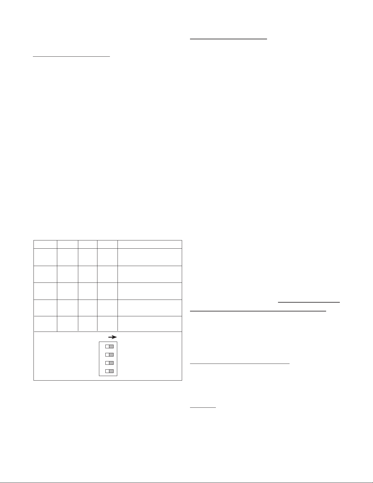
SECTION 4 INPUTS
SW1 SW2 SW3 SW4 Conditioning
ON ON --- --- 0-40 Hz
min. 12.5 msec on/off
ON OFF --- --- 0-400 Hz
min. 1.25 msec on/off
OFF OFF --- --- 0-20000 Hz
min. 0.25 usec on/off
--- --- OFF OFF needs sourcing input
(drive input high)
--- --- OFF ON needs sinking input
(pull input low)
ON
S1 S2 S3 S4
4-1 Digital Pulse Inputs (continued)
4-1 Digital Pulse Inputs (Terminal 4)
Digital Pulse Inputs: The input board is a
separate board that is plugged into the mother
board just behind the display. All digital inputs
are on the same board. There are four dip
switches on the board. The input conditioning
characteristics may be altered by changing
the dip switches. A valid pulse is one which
makes a transition from the off state (low) to
the on state (high): a positive going edge.
The off state is 0 - 1 VDC with respect to
Terminal 12 (Ground). The on state is 3 - 30
VDC with respect to Terminal 12. The input
impedance is 10 K ohms. At 30 VDC, the
current draw will be 3 mA. This should be the
maximum current that the Batcher will draw.
Acceptable pulse width is determined by the
dip switch settings (See Table 4-1 below).
DIP SWITCH SETTINGS
4-1.1 STANDARD: High Impedance (Terminal
4).
Has a 10 K Ohm pull down resistor to ground
(Terminal 12) and must be driven high. Typical drivers include a contact closure from a
3-30 VDC source (such as Terminal 13), a
PNP transistor (proximity switch or other de-
vice) or an amplied signal from an inductive
pickup. Remember, the input signal must
be referenced to Terminal 12 of the Batcher.
(See Section 2-5, Fig. 2-2 Typical Digital Wiring Connections)
4-1.2 High Impedance with pull-up (Terminal
4).
Has a 4.7 K Ohm pull up resistor to +5 VDC
and must be pulled low. Typical drivers include a contact closure to Ground (such as
Terminal 12), or an NPN transistor (proximity
switch or other device). Remember, the input
signal must be referenced to Terminal 12 of
the Batcher. (See Section 2-5, Fig. 2-2 Typical Digital Wiring Connections)
Table 4-1
Idea: This input works well with TTL devices.
4-1.3 Reset Input (Terminal 5)
Identical to the Standard, High Impedance
Input with one exception. The input speed is
xed for a minimum pulse width of 5 msec.
Note: The reset input will not be changed to
a sourcing type of input even if the dip switch
is set for pull up or is changed to the pull up
settings.
4-2 Analog Inputs 5A - 5E, 6A (Terminal 4)
The input signal modules are mounted, just
like the Digital board, behind the display. Analog inputs all use the same board, likewise
so do the Analog-In/Out inputs. These boards
are not eld modiable (unlike the Digital
board). Each board is calibrated at the factory
for its particular input type.
30
Page 35

4-2 Analog Inputs (continued)
4-2.1
5A: 4-20 mA; 250 Ω input impedance.
5B: 0-20 mA; 250 Ω input impedance.
5C: 1-5 VDC; 15 KΩ input impedance.
5D: 0-5 VDC; 15 KΩ input impedance.
5E: 0-10 VDC; 15 KΩ input imped-
ance.
The above inputs take the analog signal and
scale it from 0 to 10000 pulses per second
by using a highly linear voltage to frequency
converter. These pulses go to the processor
to be scaled by the K Factors. To determine
the K Factor, see Section 7, Calculating the K
Factor.
4-2.2
6A: Square Law: 4-20 mA; 250 Ω in-
put impedance.
The Square Law input is a special input that
compensates for non- linear input types.
Specically, inputs that require square root
extraction to provide accurate count and rate
determinations. The input signal is converted
to a 0 to 10000 pulse per second input to the
processor (See Table 4-2 below).
mA Input Freq. mA Input Freq.
4 0000 10 6123
5 2500 12 7071
6 3535 16 8660
7 4330 18 9354
8 5000 20 10000
Table 4-2
To calculate the freq. for a particular input use
the following formula.
mA - 4 x 10000 = Freq. to processor
16
For example: to calculate the frequency for 9
mA Input.
9 - 4 x 10000 = 5590 Freq. to processor.
16
4-2.3 Analog Inputs Exchange
If an analog sensor cannot be obtained that
matches the Batcher input, it is recommended
that the Batcher be returned to have the analog input module exchanged and recalibrated.
Recalibration should only be attempted by
someone who has the training to open the unit
and work with grounded equipment necessary
to protect the static sensitive CMOS circuitry.
For instructions on how to return the unit for
exchange see Section 2-2.
4-2.4 Analog Inputs Calibration
(All units have been calibrated at the factory)
Warning: This unit contains static sensitive
components. Observe proper precautions!
a) Set the ratemeter at 6 SIG FIG; the win-
dow at 01; and the K Factor at 1.00.
b) Remove the case and locate the analog
input card mounted behind the display
(see Section 6-3).
c) Locate the two 0.3 inch square pots R3
and R15. These numbers should be
silkscreened underneath them on the
board.
d) Input a very accurate low signal and ad-
just R3 (left side from the front) so that
the display reads .0001 to 0000.
e) Input a very accurate high signal and
adjust R15 (right side from the front) so
that the display reads 9999 to 10000.
f) Repeat steps d and e until the unit is
reading as close as possible to 0000 on
the low side and 10000 on the high side.
This should only take a few tries.
g) Re-case the unit and setup the Menu as
desired.
If problems occur during calibration please contact the factory for exchange or to arrange for
factory calibration.
31
Page 36

4-3 DC Power Inputs (Terminals 12, 14)
!
SECTION 5 OUTPUTS
The Batcher may be powered by an external
DC power supply. The supply must provide 12
- 27 Volts DC and at least 280 mA of current.
The positive side (+DC) of the DC supply should
be hooked to Terminal 14 and the negative (or
Ground) side to Terminal 12.
NOTE: Units powered by DC Voltages do not
have an isolated voltage out on Terminals 15
and 16 or +12 VDC on Terminal 13.
4-4 AC Power Inputs (Terminals 17, 18)
The Batcher may be ordered for 110 or 220 VAC
power. The unit requires single phase 50/60 Hz
AC power.
The voltage range is ±15% of the rated voltage.
Voltages below this range will not power the unit.
Voltages above this range may damage the unit.
The Batcher is relatively immune from electrical
noise on the AC lines. However, in extremely
noisy applications some line conditioning or ltering may be necessary. If fusing is required,
external fusing must be supplied.
Note: The Batcher has no internal fuse to blow
out. If the unit does not function when power is
applied, contact the factory for assistance or to
arrange for repair.
The Batcher has ve different possible types
of outputs for controlling external devices or
monitoring the rate and totals. They are: Frequency Output, Relay Outputs, Open Collector
Outputs, and Optionally available Analog Output (not available on models with (Square Law
input), and RS232, RS422, or RS422M Serial
Communications.
5-1 Frequency Output (Terminal 2)
5-1.1 Electrical Characteristics of Frequency
Output
The Batcher generates a pulse out for each
factored count. A sinking NPN transistor output
(see Figure 5-0.1), can drive external devices
at various rates selected through the keypad
menu see Table 5-0.2 below). The Open Collector sinks 30 VDC maximum to 1 volt maximum
with a maximum current of 100 mA.
Speed (Hz) 10 200 2000 20000
Min. on/off (msec) 47.5 2.0 0.2 0.013
Table 5-0.2
Caution:
DC Power: 0.5 Amp
AC Power: 0.125 Amp
An external fuse is required:
Applications: Remote totalizers, ratemeters or
other monitoring devices.
10 Hz: Electromechanical totalizers
Programmable Controller inputs
200 Hz: Electronic totalizers
Programmable controllers with high
speed input cards.
2000 Hz: High speed totalizers.
20000 Hz: High speed totalizers.
32
Page 37
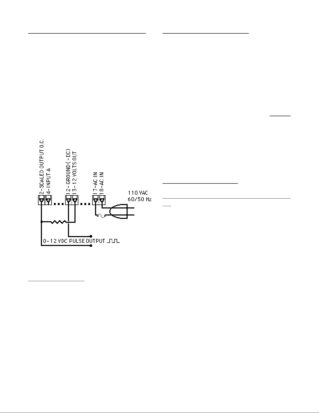
5-1.2 Internal Buffer for Frequency Output
An internal buffer will store up to 9,999 counts
if the scaled input generates pulses faster than
the output speed selected. The warning mes-
sage “DATALOST” ashes on the screen when
the buffer overows (see Section 6-1, Warning
Messages). This indicates that the counts
being totalled and the scaled outputs may be
incorrect.
Note:
All counts stored in the internal buffer will
be pulsed out at the selected frequency
even if the counter is reset before it is
nished sending them.
5-2.2 Open Collector Version (Terminal 19,
20).
The NPN, Open Collector Transistors, sink a
maximum of 250 mA at 30 VDC when active.
They behave in the same manner as the Relay Outputs (see Section 5-2.1 above). The
Open Collector outputs are available on units
with relay outputs, but, please observe the following precautions.
Note:
5-3 Optional Analog Output (Terminal 3)
When relays are used, 10 VDC is pro-
vided at the transistor outputs through
the relay coils. If current greater than
2 mA is drawn, the relay will remain
energized. Applying greater than 10
VDC to the Open Collector outputs
may destroy the unit. The transistor will sink 100 mA in the “ON”
state with relays installed.
Figure 5-0.1
5-2 Control Outputs
5-2.1 SPDT Relay Version (Standard)
When the start button is pushed, the two relays
engage simultaneously to start ow. When the
prewarn number is reached, one relay drops
out. When the preset number is reached, the
other relay drops out. The user may enter the
two numbers when setting up the batch counter
(see Section 3-3, Menu Items 1 and 2). The
contacts are rated at 10 A, 120/240 VAC or
28 VDC.
5-3.1 Electrical Characteristics of Analog Output
The Analog Output option is not available on
units with Square Law inputs. Controlled by
an Open Collector transistor, it gives a linear 4
to 20 (or 0 to 20) mA sink which corresponds
to displayed rate or total readings. A sinking
driver pulls a current to ground, across the user’s external device (such as a strip chart recorder, computer, external meter, etc). In the
Setup mode the user is prompted to set the
output to correspond to rate or total and set
the low and high (4/0 to 20mA) parameters to
which the analog signal will correspond.
Idea:
The Batcher can supply the 24VDC to
power the current loop. (Connect pin
15 to 13, Pin 16 is now +24 VDC with
respect to pin 12.) Connect Pin 16 to
the + DC side of the external device
and connect Pin 3 to -DC side of the
external device (see Figure 5-2.1).
33
Page 38
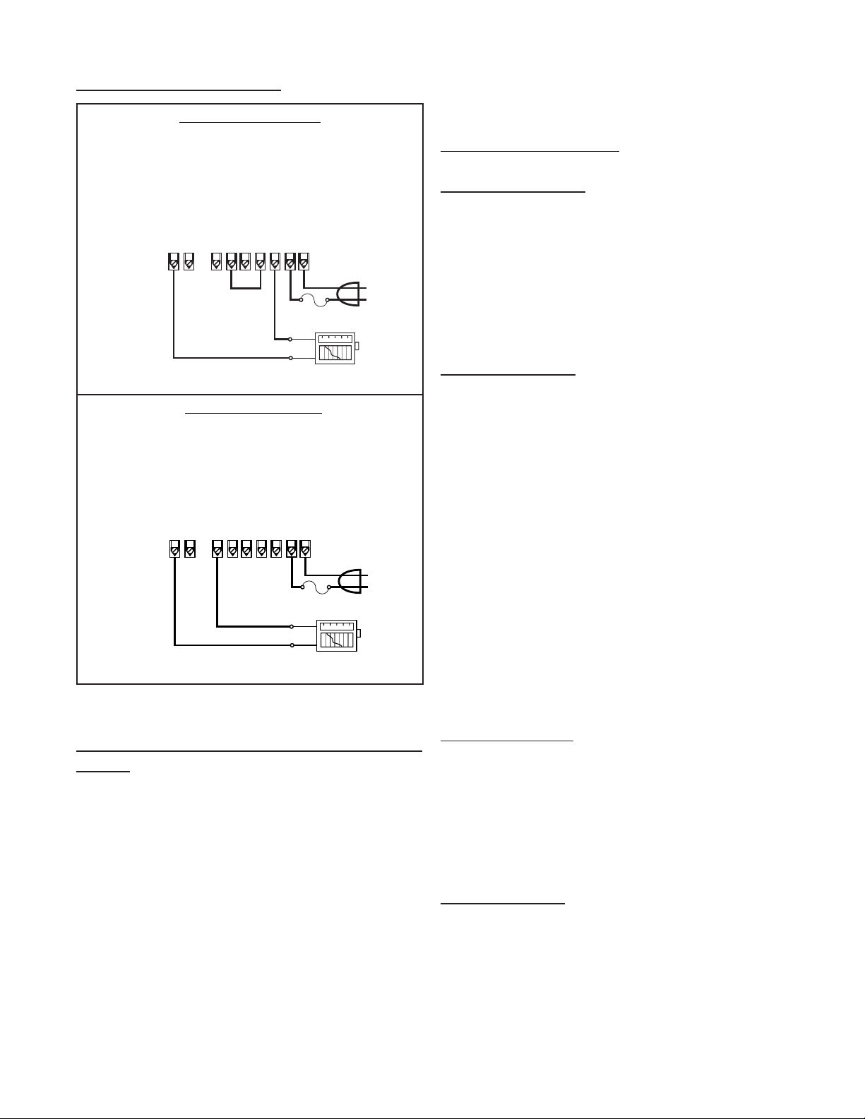
5-3 Optional Analog Output (continued) SECTION 6 TROUBLE SHOOTING AND
3 • Analog Output
4 • Input A
12 • Ground (-DC)
13 • (+) 12 Volts Out
14 • (+) DC Power In
15 • Isolated 12 V (-)
16 • Isolated 12 V (+)
17 • AC In
18 • AC In
110/220 VAC
Strip Chart
Recorder
+
–
4-20mA Source
4-20mA Return
Fuse
3 • Analog Output
4 • Input A
12 • Ground (-DC)
13 • (+) 12 Volts Out
14 • (+) DC Power In
15 • Isolated 12 V (-)
16 • Isolated 12 V (+)
17 • AC In
18 • AC In
110/220 VAC
Strip Chart
Recorder
–
+
Voltage Out Source
Voltage Out
Return
Fuse
MAINTENANCE GUIDE
4-20 mA Out Wiring
6-1 Warning Messages
6-1.1 PREWRONG
Indicates that the values in Preset and Prewarn
are not acceptable. This condition will occur
when the Preset value is less than the Prewarn
value. The display will continue to display this
message until the error is corrected. To change
the Preset and Prewarn values see Section 3-3,
Setup Procedure.
6-1.2 DATALOST
Warning message that indicates the unit is
Voltage Out Wiring
receiving pulses faster than 20000 pulses per
second or the data buffer is full. In either case
the display will not show the proper count or
rate and the frequency output will be inaccurate.
There are three possible remedies:
a) Check to see that your input is not ex-
ceeding the Batcher ratings of 20 KHz
Max. Input speed.
b) Change your OUT FREQ settings to
handle a higher count speed (Section
3-3, Menu Item 7).
c) Change your count K Factor to a larger
number, since the output frequency is
based on the factored count (Section
Figure 5-2.1
3-3, Menu Item 3).
5-4 Optional RS232 / RS422 Serial Communications
This option allows the Batcher to act as a slave
to a master terminal. It may be accessed for
counts, rate, presets and K Factors. Up to 15
units can be linked together in parallel and
addressed separately to transmit unit status
or accept new set points using the standard
ASCII format. Baud rates of 300, 600, 1200,
2400, 4800 or 9600 as well as choice of odd,
even, space, or mark parity can be selected by
keypad control. Further information and more
details are provided in Section 8 at the end of
this manual.
6-1.3 RFFFFFFF
Indicates that the factored input rate has exceeded a 7 digit number. The ratemeter cannot handle numbers larger than 7 digits (i.e.
9999999). Change the Rate K Factor to a larger
number (Section 3-3, Menu Item 3) to correct
this problem.
6-1.4 LOCK ON
Indicates that the unit has been locked out!
The unit must be unlocked before any changes
can be made. See Section 3-3, Menu Item 4
to unlock the unit.
34
Page 39

6-1 Warning Messages (continued)
6-1.5 BAD FREQ
Indicates that the values in the 16 Point setup
are not acceptable. This condition will occur
when the frequency values are not in ascending
order. The display will continue to display this
message until the error is corrected. To correct
the error see Section 3-3, Setup Procedure.
6-1.6 SECURITY
Indicates that no signal has come in for the duration time set in the Lockout menu. Lockout code
must be entered before the unit will continue.
Section 3-3, Setup Procedure.
6-2 Troubleshooting
6-2.1 General
The following troubleshooting procedures have
been developed as an aid in locating defects.
Not every possible problem has been listed,
but a general isolation procedure for tracking
down problems has been given. A standard
recommendation is the removal of power for
2 seconds. This allows the microprocessor to
go through a reinitialization cycle at power up.
If it is determined that the unit is faulty, contact
your local Factory Representative or Sales Of-
ce concerning replacement. The Batcher is
not eld serviceable and all repairs should be
performed by the factory.
6-2.2 Problems
Symptom: Display will not light.
Possible Cause: No power to unit, power to unit
not to specications or bad connection between
display board and mother board.
Test Procedure: See Specications Section 1-4
for proper input voltages. Then;
Check AC voltage input on terminals 17 &
a)
18.
(if DC Powered unit) Check DC voltage input
b)
on terminals 12 & 14.
Check connection of display board to mother
c)
board
Corrective Action: If all checks okay, replace
unit.
6-2.2 Problems
Symptom: Unable to start batch.
Possible Cause #1: Displayed Batch count already exceeds the Preset value.
Test Procedure: Check Preset value against
the displayed value. If the Preset is less, go to
corrective action.
Corrective Action: Reset the unit by pressing the CLR button or change the Preset to a
larger value.
Possible Cause #2: Incorrect programming.
Test Procedure: Check for programming errors, review manual.
Corrective Action: Reprogram unit as required.
Possible Cause #3: Defective Circuit board or
component.
Test Procedure: Press the Start button and
check for relay action. An OHM meter across
the appropriate relay terminals should give
the proper indication. (Be sure to disconnect
all power to the relay terminals rst!)
Corrective Action: If no relay action replace
unit.
Symptom: Unit not totalizing.
Possible Cause #1: Incorrect programming.
Test Procedure: Check for programming errors, review manual. For Example, if the K
Factor is too large it may take some time before a count is registered on the display.
Corrective Action: Reprogram unit as required.
Possible Cause #2: Input signal invalid.
Test Procedure: See Specications Section
1-4 for proper input signals. Then use oscilloscope to;
a) Check Analog input on terminals 3 and
12 for proper current or voltage levels.
b) (if Digital unit) Check Digital voltage in-
put on terminals 3 and 12.
Corrective Action: If inputs check okay, replace unit.
35
Page 40

6-3 Removing the Case
To install or change the input or data interface
cards, the case must be removed. Remove
all power before opening the case. CMOS
logic is used so observe standard precautions
against damage by static discharge. On units
RS232 or RS422, two screws on the back,
holding the top left connector, have to be re-
moved. Next, remove the six (6) at head
screws behind the front bezel and lift off the
bezel assembly. Slide the main board display
out the front of the case by pushing from the
rear. Once modications are made, reverse
the procedure to reassemble the unit. Make
sure that the main board is in the track. The
six (6) screws that hold the panel must be
tight to seal the rubber keypad panel assembly, approximately 0.6 in-lb torque.
6-3.1 Input Card Modication
Follow the instructions for removing the case
in Section 6-3. The Input card is mounted just
behind the display and plugs onto the 15 pin
post connector. Remove the board and make
desired changes. When installing the Input
card, make sure that the component side of
the board is facing the front and that the 15
pin connector is mated properly and not offset
to the side. Replace the front panel per Section 6-3.
6-3.2 Serial Communications Interface Installation
Follow the instructions for removing the case
in Section 6-3. The RS232, RS422 and
RS422M cards have a 15 contact ribbon cable that plugs into the female connector next
to the heat sink. Choose the proper Interface
card. With components on top and subminiature connector to the back plug in the harness
and mount the card on the four (4) standoffs
provided. After the main board is inserted into
the case replace the front panel as per Section 6-3.
SECTION 7 CALCULATING THE K FACTORS
7-1 General
The key to accurate ow measurement with
the Batcher is correct scaling. The electronics of the unit have been designed for stability
and repeatability. Even the nest measuring
device and equipment cannot make up for improper factoring and programming. Due to the
complexity of the concept of K Factors, this
special section has been provided for those
who still nd it hard to understand. A separate
worksheet has also been provided with this
manual to help in calculating the K Factors.
It is hoped, that between this section of the
manual and the worksheet, that any questions
you may have, regarding the K Factor, will be
answered.
7-1.1 What is a K Factor?
The K Factor is a divider. This means that if
the K Factor is greater than 1, it will diminish
any input signal. Conversely, if it is less than
1, it will increase any input signal. The K Factor range of the Batcher is from 0.0001001 to
99999999. This allows a wide range of factoring from greatly increasing (to display a large
value) to decreasing the input (to display a
very small value).
6-4 Maintenance
The Batcher does not require any “Routine Maintenance” by the user. If a problem
should occur, and all troubleshooting procedures have been exhausted, contact your local representative or distributor (phone number on cover of manual).
36
Page 41

7-2 Calculating the K Factors.
The following steps are the recommended
procedure forcalculating the K Factors. Take
your time and go through the procedure slow-
ly at rst. After several tries you should be
fairly adept at calculating the K Factor for any
given input.
7-2.1 Calculating the K Factor for Digital Pulse
Inputs.
Given the sensor K-factor and desired decimal point position for the Total (Count) display
calculate the K-Factor as follows:
Step 1. From the documentation provided
with the ow sensor, determine
the average sensor K-factor.
Step 4. Enter the Count K-Factor as de-
scribed in Section 3-3 referencing
the Programming Flowchart (3-4)
as needed.
Step 5.
Determine the necessary TF (time
factor) given the ow rate time base
you wish to have displayed on the
device using the following table:
TIME FACTOR (TF)
Rate Display Desired TF
Rate / second 1
Rate / minute 60
Rate / hour 3600
Rate / day 86400
TABLE
Example : Sensor K-factor = 122 pulses/
gallon which means the sensor
produces 122 pulses for each
gallon passing through the owmeter.
Step 2.
Determine the necessary DPF for
the desired total decimal point location you wish to use in displaying
total on the instrument from the following table:
DPF Table
Desired Total
Decimal Location: DPF
XXXXXX. 1
XXXXX.X 10
XXXX.XX 100
XXX.XXX 1000
XX.XXXX 10000
X.XXXXX 100000
Example: for X.X, DPF = 10
Example: For display of rate per minute;
TF = 60
Step 6. Compute the Rate K-Factor from
the average sensor K-Factor and
the TF selected.
Rate K-Factor = Sensor K-Factor
TF
Example: Rate per minute:
Rate K-Factor = 122 = 2.0333
60
Step 7. Enter the Rate K-Factor as de-
scribed in Section 3-3 referencing
the Programming Flowchart (3-4) as
needed.
Step 3. The Count K Factor may be computed
as follows:
Count K-Factor = Sensor K-Factor
DPF
Example: Count K-Factor of 122/10 = 12.2
37
Page 42

7-2.2 Calculating the K Factor for Analog
Inputs.
Step 3. The Count K Factor may be computed
as follows:
Obtain the Flow Rate value that corresponds
to the meters full scale signal. This should
be specied on your device or with its paper
work.
Example: 20 mA = 200 Gal / min
The unit converts the analog input span to a
0-10000 Hz frequency. Given the full scale
ow rate that corresonds to the analog input
span, and the Time Factor (TF) that corre-
sponds to the equivalent ow rate time base,
the K-Factors can be calculated as follows:
Step-1 Calculate the equivalanet sensor KFactor as follows:
Equivalent Sensor K-Factor =
10000 * TF
Full Scale Flow Rate
Example: 4 to 20 mA corresponds to 0-200
Gal/min
Count K-Factor = Sensor K-Factor
DPF
Example: Count K-Factor of 3000 /10 =
300
Step 4. Enter the Count K-Factor as de-
scribed in Section 3-3 referencing
the Programming Flowchart (3-4) as
needed.
Step 5. Determine the necessary TF (time
factor) given the ow rate time base
you wish to have displayed on the
device using the following table:
TIME FACTOR (TF) TABLE
Rate Display Desired TF
Rate / second 1
Rate / minute 60
Rate / hour 3600
Rate / day 86400
Equivalent Sensor K-Factor =
10000 * 60
200
= 3000 pulses/gal
Step 2. Determine the necessary DPF for
the desired total decimal point location you wish to use in displaying
total on the instrument from the following table:
DPF Table
Desired Total
Decimal Location: DPF
XXXXXX. 1
XXXXX.X 10
XXXX.XX 100
XXX.XXX 1000
XX.XXXX 10000
X.XXXXX 100000
Example: for X.X, DPF = 10
Example: For display of rate per minute;
TF = 60
Step 6. Compute the Rate K-Factor from
the average sensor K-Factor and
the TF selected.
Rate K-Factor = Sensor K-Factor
TF
Example: Rate per minute:
Rate K-Factor = 3000 = 50
60
Step 7. Enter the Rate K-Factor as de-
scribed in Section 3-3 referencing
the Programming Flowchart (3-4) as
needed.
38
Page 43

7-3 Calculating 16 Point K Factors
Units equipped with the 16 Point option allow the
user to enter in from 3 to 16 different frequency
points (inputs per second) and assign different K
Factor dividers from 0.00011 to 999999 for each
of these frequencies. The 16 Point unit determines the incoming frequency and calculates a K
Factor line slope from the two closest data points
that had been entered. The specic K Factor is
then proportionally interpolated using 8 position
oating math. This K Factor is applied to all inputs until the next frequency calculation, usually 1
second later. If a 0 frequency is entered into point
1, the point 1 K factor will be applied to all inputs
received before the rst frequency calculation.
In order to keep track of data, each Frequency / K
Factor data entry is assigned a point number. Any
point number may be selected to view and / or
change the Frequency / K Factor data as long as
the frequencies of the ascending point numbers
are also entered in ascending frequencies. 7-3.1
Some Notes on 16 Point Setup
1) The unit will not accept a K Factor of (0) zero.
If a zero is entered the unit automatically puts
a (1) one in its place. Division by zero is not allowed.
auto-ranging decimal point in the rate display will
be shifted to the left as the dummy decimal is
shifted to the left. This is so that the rate display will be as same as the count. For example:
The input pulses are coming in at 100 pulses per
minute. The decimal point is set at (1) one (DEC
LO.C). At the end of one minute the count will
read 10.0. During the minute the rate will read
10.0 while it would show 100.0 if no decimal point
were added.
7-3.2 Test Mode Operation and K Factor Calculation
A special TEST mode can be accessed through
the 16 Point setup menu. This is used to help set
the points and K Factors as well as calibration of
the metering device. If TEST is selected, the K
Factor is set to (1) one for all frequencies. Thus,
the totalizer will accumulate one count for each incoming pulse. Below are steps for calculating the
K Factors with pulsing devices or analog transmitters.
1) Set the 16 Point unit to TEST and press ENT
on POINT 00 to go to the run mode.
2) At the lowest desired ow rate, reset the counter and let the unit count the incoming signal while
the rate displayed is recorded.
2) Point 01 will be the low shut-off frequency.
Below this frequency no rate will be displayed nor
count recorded. Point 01 should be assigned a
frequency of (0) zero with a K Factor for lowest
ow especially if very slow ow is to be counted.
3) The entry of a frequency of (0) zero for Point
03 or above will tell the unit to continue the K Factor slope line calculated from the two previous
Frequency / K Factor points and ignore any higher
point data. If a xed K Factor is desired, assign
the same K Factor to two ascending frequency
points and enter a frequency of (0) zero in the
next higher point entry.
4) Extrapolated K Factors are always positive
numbers. Make sure that the last two points do
not project the K Factor slope towards zero.
5) The dummy decimal point is still set up with
DEC LOC menu under DEV TYP. However, the
3) Interrupt the input signal when the known
tested amount has gone through the metering device. Switch to count display and read the number
of counts that came in from the known volume as
displayed on the unit. Divide the counts by the
volume that passed through the meter to determine the number of counts for 1 unit of measure,
gallon, cubic feet, etc.
4) Record this frequency and K Factor for later
entry into Point 01 or Point 02. (See 7-3.1 Note 2
to determine if the data should be entered in point
1 or 2)
5) Assign ascending point numbers to corresponding ascending frequencies when recording
Frequency / K Factor data. Repeat process until
desired number of points are set up.
39
Page 44

SECTION 8 SERIAL COMMUNICATIONS
This section applies to units which have the
Serial Communications interface option. Up
to 15 units can be linked together. Unit status can be accessed and new set points and
K Factors can be entered through the serial
port. The unit cannot be taken out of the Run
Mode through the serial port. Menu changes
must always be made through the front keypad (except Preset, Prewarn, and K Factors).
Data is transmitted at selected baud rates using standard seven bit ASCII characters and
parity with two additional bits of “Start” and
“Stop” to make up the standard ten bit character.
8-1 Unit Code
Each Batcher in the hookup must be assigned
a code number from 1 to 15, through the front
keypad, in the OUTCARD setup mode (see
Section 3-3, Menu Item 5). Number “00” is
reserved for a dedicated hookup to only one
terminal and its transmit output line remains
in an “on” active state. (Units assigned other
numbers have outputs that remain in the “off”
high impedance state until addressed by their
code number or brought on line by a positive
edge of the Strobe input). Once a unit is addressed, do not address another unit until the
data has been sent and any data requested
has been transmitted back.
8-2 Baud Rate
The Baud rate is the speed at which data is
transmitted, expressed in bits per second.
Baud rates of 300, 600, 1200, 2400, 4800, or
9600 are available. Use the front keypad to
call up the OUTCARD setup mode (see Section 3-3, Menu Item 5) and select the desired
baud rate that is compatible with the remote
terminal.
8-3 Parity
Parity is a bit of information that is inserted before the stop bit and is used to help
check if the transmission is correct. In the
OUTCARD setup mode, select between:
a) ODD (Parity bit is logical zero if total
number of logical 1’s in the rst seven
bits is odd)
b) EVEN (Parity bit is logical zero if total
number of logical 1’s in the rst seven
data bits is even.)
c) MARK (Parity data bit is always logical
1.)
d) SPACE (Parity data bit is always logical
0.).
The Batcher does not check the parity but
does transmit the parity chosen.
Idea: Use the MARK parity for terminals that
need two stop bits and/or no parity
since these terminals ignore the parity
anyway.
Note: If the parity of the terminal is not
known, it is often practical to key in a different
parity until the correct one is found.
8-4 RS232 Electrical Requirements
The Batcher uses standard EIA specications.
Standard inputs must present a load of 3000
to 7000 ohms. A voltage level of +3 V to +25
V (referenced to signal ground) is read as a
“Space” or “0” and indicates an active state
(asserts a control line). A voltage level of -3
V to -25 V (referenced to signal ground) is
read as a “Mark” or “1” and does not indicate
an active state (does not assert a control line).
Outputs must send a voltage of +5 V to +25
V (referenced to signal ground) for a “Space”
and a voltage level of -5 to -25 V for a “Mark”
when loaded with a 3000 ohm load to signal
ground. Outputs must be capable of being
shorted to other signal lines without burning
out.
Note: It is normally recommended. that cable
length be limited to 50 feet.
40
Page 45

8-5 RS232 Card Wiring
This option has a subminiature D, 25 pin, female connector and is wired as a DCE (Data
Communications Equipment) device. If it is
connected to a DTE (Data Terminal Equipment) device, the interconnect cable should
have wires 2 and 3 connected straight to the
same pins on each end.
If it is connected to another DCE device, Pins
2 and 3 must be crossed. This means that
the wire to pin 2 on one end goes to pin 3 on
the other end and the wire to pin 3 on one end
goes to pin 2 on the other end.
8-5.1 Wiring Diagram RS232 / Strobe (25 Pin
Connector)
8-6 RS422 Electrical Requirements
The input of the Batcher follows the standard
EIA high impedance minimum of 12 K Ohms.
When the 422+ (A) input is more positive
than the 422- (B) input by 0.2 V to 6 V, a “1”
or “Mark” condition is recognized. When the
422+ input is more negative than the 422- input by 0.2 V to 6V, a “0” or “Space” is recognized. Data is recognized by the polarity of
the voltage difference between the two lines.
Noise picked up in the line will make little
difference since the noise is usually added
to each line and the voltage differential remains the same. The output driver drives the
transmit lines to a differential of 2 to 6 V. It is
designed to handle loads up to 60 mA of sink
or source current and features positive and
negative current conditions. Since the RS422
is more immune to noise, cable links up to
1000 feet or more can be used. Because of
the high input impedance of RS422, line terminating loads are recommended. For hookup to a single unit, a 150 to 200 Ohm resistor
across Receive Data+ and Receive Data(-),
at the Batcher and at the remote terminal is
often sufcient. For multiple hookups, other
standard terminations should be used. Note:
Total loading should not be greater than 90
Ohms.
8-5.2 RS232 Wiring Notes
The Batcher requires only three wires for
RS232 communication:
a) Pin 7 (Signal Ground)
b) Pin 2 (Receive Data)
c) Pin 3 (Transmit Data)
Other pins are jumped to simulate appropriate
responses required for some terminals.
a) Pin 4 (Request To Send), Pin 5 (Clear
To Send). Jumped internally to echo
back signals.
b) Pin 6 (Data Set Ready), Pin 8 (Re-
ceived Line Signal Detector), Pin 20
(Data Terminal Ready). Jumped internally to echo back signals.
41
Page 46

8-7 RS422 Card Wiring
This option has a subminiature D, 37 pin, female connector and is wired as a DCE (Data
Communications Equipment) device. It is
designed to be connected to a DTE (Data Terminal Equipment) device. If it must be connected to a DCE device, it will be necessary
to cross wires 4 and 6 as well as 22 and 24 at
one end of the connector harness.
8-7.1 Wiring Diagram RS422 / Strobe (37 Pin
Connector)
8-7.2 RS422 Wiring Notes
The Batcher requires only four wires for
RS422 communication:
a) Pin 22 (Receive Data +A)
b) Pin 4 (Receive Data -B)
c) Pin 24 (Transmit Data +A)
d) Pin 6 (Transmit Data -B)
Other pins are jumped to simulate appropriate
responses required for some terminals.
a) Pins 7, 25 (Request To Send), Pins 9,
27 (Clear To Send). Jumped internally
to echo back signals.
b) Pins 11, 29 (Data Set Ready), Pins 13,
31 (Received Line Signal Detector),
Pins 12, 30 (Data Terminal Ready).
Jumped internally to echo back signals.
8-8 Strobe Input Electrical Requirements
Both the RS232 and RS422 interface option
cards have inputs that allow data to be requested over a separate strobe input and a 3
bit, data request, code input. Any number of
unit’s, data request, code lines can be linked
in parallel; as long as the source can drive
the combined load of all inputs linked together
(1.5 K Ohm divided by the total number linked
together). Data is transmitted over the serial
lines using standard RS232 or RS422 characteristics.
Note: Strobe and data request inputs are positive true with signal ground as reference:
8-8.1 Strobe Input Levels
0 or low: Open or 0 to 1 VDC
1 or high: 3 to 30 VDC
Impedance: 1.5 K Ohm
42
Page 47

8-9 Strobe Wiring
8-9.1 RS232 Strobe Wiring (RS232, 25 Pin
Connector)
The 3 data lines are hooked up to Pins 9, 10,
and 11. These lines must be held high while a
strobe of at least 25 milliseconds is given on
Pin 18. Data is transmitted in RS232 serial
format on the Transmit Data Line (Pin 3).
a) Pin 9, Binary 1’s Input
b) Pin 10, Binary 2’s Input
c) Pin 11, Binary 4’s Input
d) Pin 18, Strobe Input
e) Pin 3, Transmit Data
f) Pin 7, Signal Ground for Reference
Refer to 8-5.1 Wiring Hookup RS232 / Strobe
(25 Pin Connector) for diagram.
8-9.2 RS422 Strobe Wiring (RS422, 37 Pin
Connector)
The 3 data lines are hooked up to Pins 9, 10,
and 11. These lines must be held high while a
strobe of at least 25 milliseconds is given on
Pin 3. Data is transmitted in RS422 format on
the Transmit Data Line (Pins 6, 24).
a) Pin 21, Binary 1’s Input
b) Pin 14, Binary 2’s Input
c) Pin 10, Binary 4’s Input
d) Pin 3, Strobe Input
e) Pins 6, 24, Transmit Data
f) Pins 19, 20, Signal Ground for Refer-
ence
Refer to 8-7.1 Wiring Hookup RS422 / Strobe
(37 Pin Connector) for diagram.
8-10 Serial Interface Operation
Data is received and transmitted over standard EIA RS232 or RS422 levels. To address a Batcher unit, transmit a “D” (device)
followed by the 1 to 15 code number and a
“Space”. Once the space has been received the Batcher becomes active and responds back, “Device XX:” (Device number).
(Once active, the unit works in a full duplex
echo back mode, so that data sent from the
terminal will be transmitted back for verication.) Once the unit is “on line”, use the
proper serial transmit codes to request data
or set a new value. (See Section 8-10.2
RS232/RS422 Serial Input Codes). Up to 80
characters of data may be linked together and
transmitted to the Batcher (as long as there
is a space between the different codes). If an
error is made, a correction can be made by
back spacing and retyping correct data before
the “Carriage Return” (Enter) is sent. Once
“Carriage Return” (Enter) is sent, the Batcher
starts processing the data and will transmit
the requested data on a non-priority basis
over the data transmit line. A Batcher keypad
entry or incoming data will halt the data communication cycle. Therefore, there should be
a pause after data is requested to insure that
all data has been transmitted before another
unit is addressed and brought on line. When
transmitting, the Batcher will precede each
data value with a “Carriage Return” and “Line
Feed” code and answer only with requested
data in the order the requests were made.
After all requested data has been transmitted any new communication must be started
again by DXX (Device number) and space.
8-10.1 Serial Communications Timing.
If the Batcher is not busy, it should not require
more than 5 msec to process each request.
To nd the cycle time to process and transmit a request, calculate the bit transmit time
by dividing 1 by the baud rate; multiply that
by 80 (8 characters each; 10 bits per character); add 5 msec. to this product and multiply
by the number of requests made. Example:
Typical time to transmit 1 uninterrupted request at 300 baud rate is .272 sec = (1÷300)
x (80) + 0.005. This time will be extended if
the Batcher must service the front keypad or
one of the inputs. In practice, if transmission
has not started within 2 seconds after data is
requested, it can be assumed that there is a
problem.
43
Page 48

8-10.2 RS232/RS422 Serial Input Codes
DXX(S) (Device and address number followed
by space) activates the Batcher that had
been assigned that number. That unit comes
on line and transmits “Device XX:”. Unit is
now ready to receive a code or string of codes
separated by a space. A “Carriage Return”
(Enter) code enters the codes and processing
of requests begins.
Note: After device is activated, there must be
a delay to allow “Device # _ _” to be
transmitted by the unit before any new
commands are sent to the unit.
DC Will transmit Count.
DR Will transmit Rate.
DT Will transmit Grand Total.
GO Will start the unit on a Batch.
KC Will transmit counter K Factor.*
KC(S)XXX Will load Counter K Factor num-
ber.*
KR Will transmit Rate K Factor.*
KR(S)XXX Will load Rate K Factor number.*
PA Will transmit Preset value.
PA(S)XXX Will load Preset value number.
PW Will transmit Prewarn value.
PW(S)XXX Will load Prewarn value number.
RC Will reset counter to zero if
in “RO” mode (adding) or set
counter to Preset value if in “SP”
mode (subtracting). Output is
reset.
RC(S)XXX Will set counter to number (no
other change is made).
RT Will reset Grand Total to zero.
RT(S)XXX Will reset Grand Total to number.
ST Will stop the unit from the batch
in progress.
* See Section 8-10.4 for 16 Point Option data
entry commands.
8-10.3 RS232/RS422 Serial Input Examples
Example A: (S) = Space
Transmit from terminal Receive from Batcher
D13(S) [Unit 13 activated] Device #13
PA(S)76546(S)PA(S) PA 76546 PA
KC(S)1575(S)KC(S) KC 1575 KC
RC(ENTER) RC
{Preset set to 76546, Count K Factor set to 1575, and Counter
is reset.}
Example B: (S) = Space
Transmit from terminal Receive from Batcher
D7(S) [Unit 7 activated] Device #7
PA(S)12347(S)PA(S) PA 12347 PA
RC(S)456789(S)RCC(S) RC 456789 RC
RT(S)376(S)DT(ENTER) RT 376 DT
{Batcher Preset set to 12347, Counter set to 456789, and
Grand Total set to 376.}
8-10.4 16 Point Data Entry Commands
FA Will transmit frequency of A
(Point 01)
KA Will transmit K Factor of A
(Point 01)
FA(S)XXX Will load frequency into A
(Point 01)
KA(S)XXX Will load K Factor into A
(Point 01)
FB Will transmit frequency of B
(Point 02)
KB Will transmit K Factor of B
(Point 02)
- - (Use letters A to O for Points
01 to 16)
FO Will transmit frequency of O
(Point 16)
KO Will transmit K Factor of O
(Point 16)
FO(S)XXX Will load frequency into O
(Point 16)
KO(S)XXX Will load K Factor into O
(Point 16)
To request a transmit of data, send a code for
information desired. To change data, send
the desired address code followed by a space
and the new number desired.
44
Page 49

8-10.5 RS232/RS422 16 Point Serial Input
Example
Example : (S) = Space
Transmit from terminal Receive from Batcher
D11(S) [Unit 7 activated] Device #11
FC(S)500(S)KC(S)305 FC 500 KC 305
{Frequency for C (Point 03) is set to 500,}
{K Factor for C (Point 03) is set to 305.}
FC(S)KC(S)(ENTER) FC KC
{Unit echoes back commands as sent.}
Frequency of C is sent 500
K Factor of C is sent 305
8-11 Strobe Address Operation
Another method of reading the status of a unit
with either a RS232 or RS422 option is by
means of a separate strobe address and a 3
bit data request code. The strobe address
method does not allow changes of set points.
Theoretically hundreds of units could be linked
together to transmit data from the Batchers
over a serial transmit line. The units could be
assigned any code number except “00”.
The 3 bit data request code would be latched
in at the positive edge of a 3 to 30 VDC strobe
input that remained high a minimum of 25 milliseconds. Requests are processed on a nonpriority basis. Normally data will begin to be
transmitted from the Batcher over the RS232
or RS422 serial transmit lines within 5 msec
unless interrupted by a keypad entry or other
signal input.
Note:
No other unit should be brought on line
until data requested has been transmitted.
Note: There are no allowances for Frequency
or K Factor access on units with the 16
Point Option.
8-11.1 Strobe Input Codes
# DL4 DL2 DL1 Code Description
0 0 0 0 PA Will transmit Preset value.
1 0 0 1 PW Will transmit Prewarn value.
2 0 1 0 KC
3 0 1 1 KR Will transmit Rate K Factor.
4 1 0 0 DC Will transmit Count.
5 1 0 1 DT Will transmit Grand Total.
6 1 1 0 DR Will transmit Rate.
Will transmit counter K Factor.
45
Page 50

9 Programming Worksheet
Model # _____________________________
Serial # _____________________________
Unit # ______________________________
PRESET _ _ _ _ _ _ _ _
PREWARN _ _ _ _ _ _ _ _
PREset TYPe
■ EZ PRE ■ STD PRE
COUNTer
K-FACTOR _ _ _ _ _ _ _ _
Reset to 0 ■ Set to Preset ■
Decimal Location (0-8)
8 7 6 5 4 3 2 1 0
■ ■ ■ ■ ■ ■ ■ ■ ■ None
RATEmeter
K-FACTOR _ _ _ _ _ _ _ _
WINDOW (02-24) _ _
SIGnicant FIGures (1-6) _
WEIGHT (00-99) _ _
Lockout Code
SECUR _ _
CODE _ _ _ _
Output Communication (If applicable)
UNIT (00-15) _ _
Parallel ■ Serial ■
BAUDRATE 300 ■ 2400 ■
600 ■ 4800 ■
1200 ■ 9600 ■
PARITY Space ■ Odd ■
Even ■ Mark ■
Analog Output (If applicable)
Rate ■ Count ■
SET LOW 4 mA= _ _ _ _ _ _ _ _
SET HIGH 20 mA= _ _ _ _ _ _ _ _
OUTput FREQuency 20000 ■
2000 ■
200 ■
10 ■
Terminals
1 - Not Used
2 - Scaled Pulse Output O.C.
3 - Analog Output
4 - Input A (Pulse/Analog)
5 - Remote Stop/Reset Input
6 - Not Used
7 - Not Used
8 - Not Used
9 - Not Used
10 - Remote Start Input
11 - Ground (-DC), Input Common
12 - Ground (-DC), Input Common
13 - +12 Volts Out
14 - DC Power In (12 - 27 VDC)
15 - Isolate -12 Volts
16 - Isolate +12 Volts
17 - AC In
18 - AC In
19-Prewarn Transistor O.C.
20-Preset Transistor O.C.
R1-N.O
R2-N.C. Preset
R3-Common
R4-N.O
R5-N.C. Prewarn
R6-Common
46
Page 51
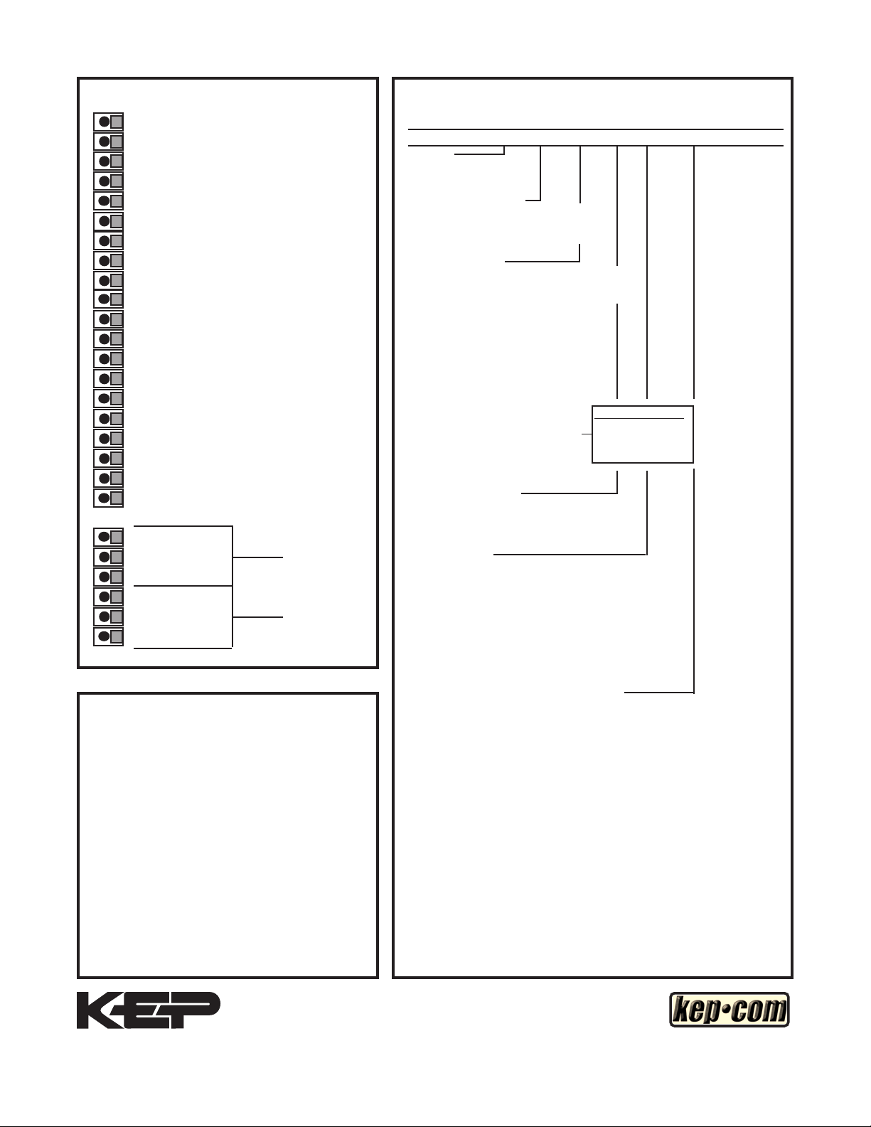
Terminals
http://www.kep.com
Ordering
1 - Not Used
2 - Scaled Pulse Output O.C.
3 - Analog Output
4 - Input A (Pulse/Analog)
5 - Remote Stop/Reset Input
6 - Not Used
7 - Not Used
8 - Not Used
9 - Not Used
10 - Remote Start Input
11 - Ground (-DC), Input Common
12 - Ground (-DC), Input Common
13 - +12 Volts Out
14 - DC Power In (12 - 27 VDC)
15 - Isolate -12 Volts
16 - Isolate +12 Volts
17 - AC In
18 - AC In
19-Prewarn Transistor O.C.
20-Preset Transistor O.C.
R1-N.O
R2-N.C. Preset
R3-Common
R4-N.O
R5-N.C. Prewarn
R6-Common
Decoding Part Number:
Example BT28 A 7AX 2 A 1 3
Series:
Batchtrol II
Operating Voltage:
A: 110 VAC ±15% or 12 to 27 VDC
B: 220 VAC ±15% or 12 to 27 VDC
Control Inputs:
* 3A: STD Pulse 3-30 VDC 20 kHz Max.
* 3B: As 3A, with 4.7 KΩ pull up resistors
5A: 4-20 mA
5B: 0-20 mA
5C: 1-5 VDC
5D: 0-5 VDC
5E: 0-10 VDC
6A: 4-20 mA Square Law
7A: 4-20mA in, 4-20mA out
7B: 0-20mA in, 4-20mA out
7C: 1-5VDC in, 4-20mA out
7D: 0-5VDC in. 4-20mA out
7E: 0-10VDC in, 4-20mA out
Control Outputs:
1: Open Collector
2: SPDT Relay 10A
Input Speed:
* A: 0-40 CPS (Inputs 3A, 3B)
* C: 0-400 CPS (Inputs 3A, 3B)
* E: 0-20K CPS (Inputs 3A, 3B)
K: Inputs 5A-5E, 6A, 7A-7E
* Dip switch selectable,
all units can be eld modied easily.
For Other Outputs:
Add X for 0-20mA out
Add Y for 0-5V out
Add Z for 0-10V out
}
WARRANTY
This product (excluding batteries) is warranted
against defects in materials and workmanship for
a period of two (2) years from the date of shipment
to Buyer.
The Warranty is limited to repair or replacement of
the defective unit at the option of the manufacturer.
This warranty is void if the product has been altered,
misused, dismantled, or otherwise abused.
ALL OTHER WARRANTIES, EXPRESSED OR
IMPLIED, ARE EXCLUDED, INCLUDING BUT
NOT LIMITED TO THE IMPLIED WARRANTIES
OF MERCHANTABILITY AND FITNESS FOR A
PARTICULAR PURPOSE.
Kessler-Ellis Products Co. 10 Industrial Way East, Eatontown, NJ 07724
Toll Free: 800-631-2165 • Phone: 732-935-1320 • Fax: 732-935-9344
Options: (Multiple Options Available)
1: RS232 Serial Interface
2: RS422 Serial Interface
3: 4-20 mA Output (Input 3A or 3B only)
3X: 0-20 mA Output (Input 3A or 3B only)
3Y: 0-5VDC Output (Input 3A or 3B only)
3Z: 0-10VDC Output (Input 3A or 3B only)
4: 16 Point Linearization Opt.
ET: Extended Temperature:
-40° to 158°F (-40° to 70° C)
ET not available with analog inputs or outputs
Accessories:
NEMATROL 4X1 - NEMA 4X/IP 65 Enclosure for
wall mounting accommodating 1 ‘TROL Series unit.
NEMATROL 4X2 - NEMA 4X/IP 65 Enclosure for
wall mounting accommodating 2 ‘TROL Series unit.
FLEXCOVER #36120
XTROL7/4- Explosion proof housing
SPARE FUSE #14039
47
 Loading...