

Page 1
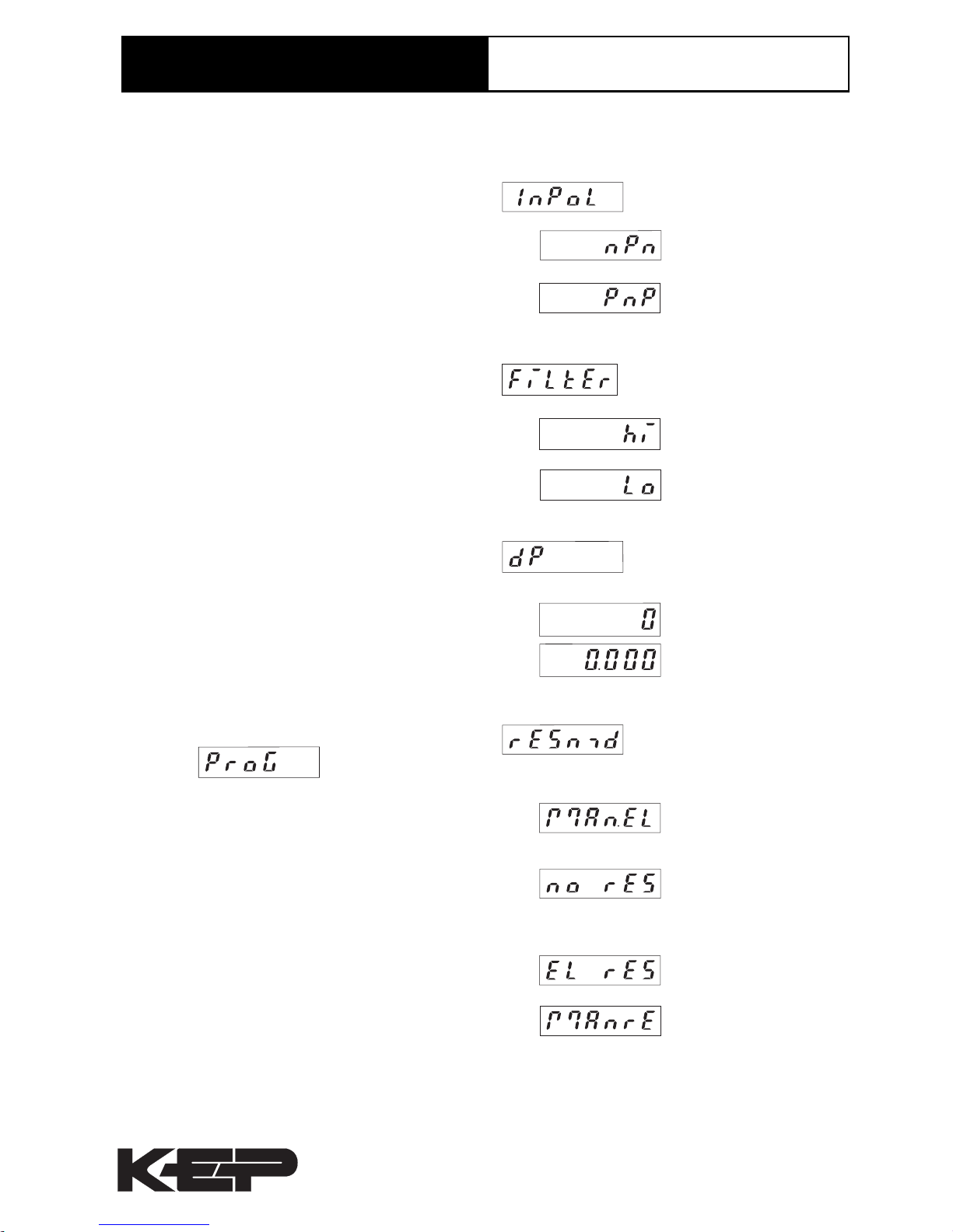
4.2 Activating the 30 Hz filter
4.3 Decimal point
4. 4 Reset mode
1. Description
• 6digit adding counter, resetab le
• LED-Display with 8 mm high characters and v ery
high luminosity
• Display range 0..999999 (ov erflow condition will be
indicated by displaying the count v alue without
leading zero blanking. The display restarts at 0.)
• Programming of count functions and operating
parameters via the setting keys . During programming
the display guides the user with text prompts .
• Supply voltage 10..30 VDC
• Programmable f eatures:
Input polarity (pnp or pnp)
Max. count frequency (30 Hz or 10 kHz)
Decimal point
Reset mode:
electrical
manual
manual and electrical
no reset
2. Inputs
INP
Dynamic count input. Max. count frequency 30 Hz or
10 kHz programmable via set up
RESET
Dynamic reset input. Link ed to the red reset ke y.
3. Setting of the operating parameters
a . Hold down keys on front panel and s witch on the
supply voltage.
b. The display shows
c . After releasing the keys the display alternates
between menu title and corresponding menu item at
a frequency of 0.5 Hz. After any k e y is pressed
down, only the menu item is display ed.
d . Pressing the right key, the menu item will be
switched to ne xt value .
e . Hold down the left key and press the right k ey to
enter and switch to the next men u title.
f. After programming the last menu item, the
programming routine will be left and the new values
will be stored by switching the menu item to „YES“.
If you chose „NO“, the programming routine will be
passed through once again.
4. Programming r outine
Programmable parameters are sho wn in succession.
After one pass, the device is fully progr ammed.
In each case the first shown item is the factory preset.
520 Series
Electronic Totalizer
Type series 520
npn: switching to 0 V
pnp: s witching to
(+ 4 - 30 V)
max. count frequency
10 kHz
max. count frequency
30 Hz
0 no decimal place
0.0 one decimal place
0.00 two decimal places
0.000 three decimal places
manual reset (red key)
and electrical reset
no reset
(red key and reset input
locked)
electrical reset only
manual reset only
4.1 Input polarity
The decimal point indicates the
number of decimal places.
KESSLER-ELLIS PRODUCTSKESSLER-ELLIS PRODUCTS
KESSLER-ELLIS PRODUCTSKESSLER-ELLIS PRODUCTS
KESSLER-ELLIS PRODUCTS 10 Industrial Way East Eatontown, NJ 07724
Toll Free:800-631-2165 • Fax:732-935-9344 99630 4/9/98
Page 2
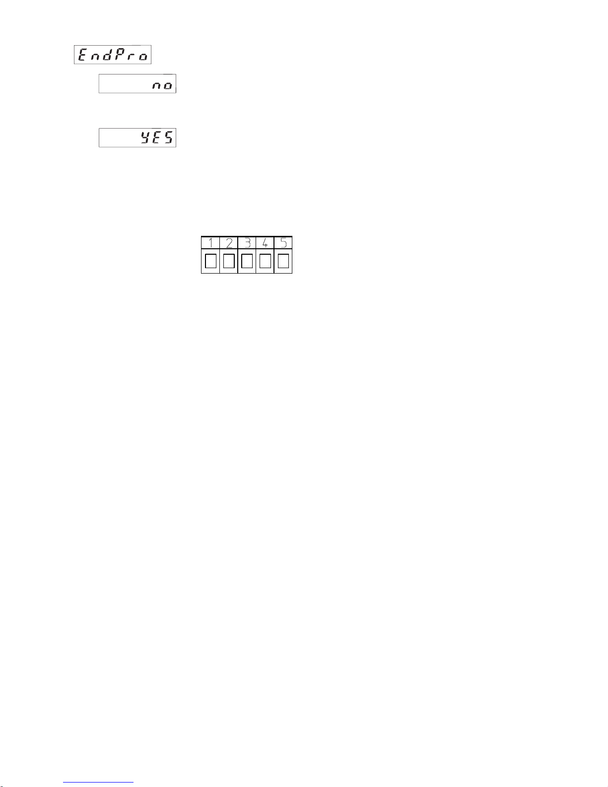
5. Connections
1 10-30 VDC
2 0 V (GND)
3 INP
4 --5 RESET
4.5 End of programming
Programming routine will
be passed through once
again. All parameters can
be checked.
Programming routine will
be left and the new
parameters will be stored.
Afterwards the device is
ready to use.
6. Technical data
Supply v oltage:
10...30 VDC
Max. current consumption:
50 mA
Display:
6digit LED-Display, 8 mm high characters
Polarity of input signals:
programmable f or both common inputs (npn or pnp)
Input resistance: appr. 10 k ohm
Count frequency: 10 kHz can be damped to 30 Hz
Min. pulse length of the control inputs: 5 ms
Input sensitivity:
Low: 0 to 1 VDC
High: 4 to 30 VDC
Pulse shape: variable (Schmitt T rigger char acteristic)
Data retention:
via EEPROM 1x10
6
memory cycles or 10 years
Noise immunity:
EN 50081-2; EN 55011 class B; EN 50082-2
Ambient temperature: +14°F...+122°F (-10 °C...+50 °C)
Storage temperature: -13°F ...+158°F (-25 °C ...+70 °C)
Weight: appr . 1.76 oz.(50 g)
Protection: IP 65 (front)
Cleaning:
The front of the unit is only to be cleaned with a soft wet
(water !) cloth.
7. Dimensions:
W = 1.88“ (48mm) H = .944“ (24mm) D = 2.32“ (59mm)
8. Cutout:
W = 1.78“ (45.2mm) H = .876“ (22.3mm)
With adaptor: W = 1.97“ (50mm) H = 0.99“ (25mm)
 Loading...