

Page 1

UD COMPONENT SYSTEM/COMPACT HI-FI SYSTEM
UD-952
INSTRUCTION MANUAL
KENWOOD CORPORATION
DIGITAL AUDIO
For your records
Record the serial number, found on the back of the unit, in the spaces designated on
the warranty card, and in the space provided below. Refer to the model and serial
numbers whenever you call upon your dealer for information or service on the product.
Model___________________________Serial Number____________________________
B60-1795-00 (35) (K, P, E, T, M, X)[^
95/12 11 10 9 87 6 5 432 1 94/12 11 10987
Page 2
Before applying power
A Caution: Read this page earefuiiy to ensure safe operation.
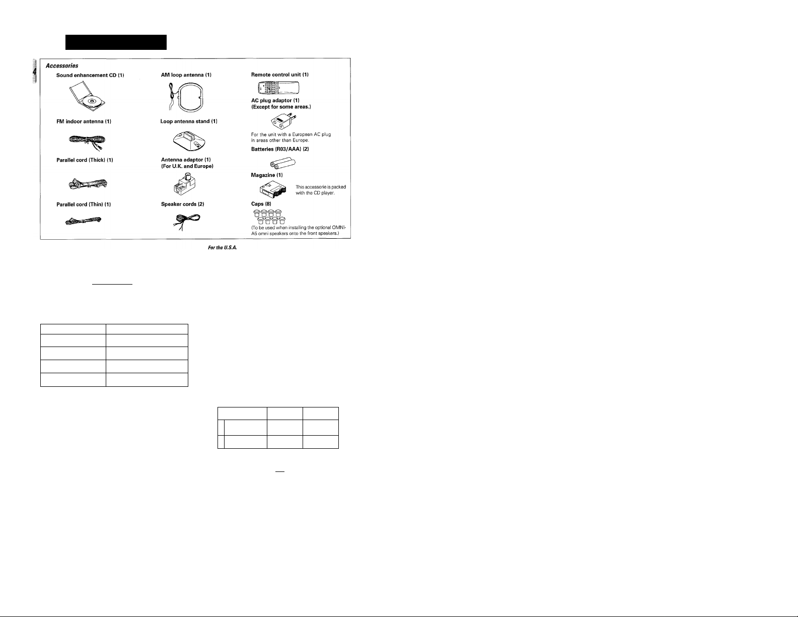
Unpacking
, Unpack the unit carefully and make sure that all accessories are put aside so they will not be lost.
Examine the unit for any possibility of shipping damage. If your unit is damaged or falls to operate, notify your dealer immediately. If your unit was
shipped to you directly, notify the shipping company without delay. Only the consignee (the person or company receiving the unit) can file a claim
against the carrier for shipping damage.
We recommend that you retain the original carton and packing materials for use should you transport or ship the unit in the future.
Before applying power
Units are designed for operation as follows.
U.S.A. and Canada..................................................................120 V only
U.K. and Australia...................................................................240 V only
For the United Kingdom
Factory fitted moulded mains plug
1. The mains plug contains a fuse. For replacement, use only a 13-Amp
ASTA-approved (BS1362) fuse.
2. The fuse cover must be refitted when replacing the fuse in the
moulded plug.
3. Do not cut off the mains plug from this equipment. If the plug fitted
is not suitable for the power points in your home or the cable is too
short to reach a power point, then obtain an appropriate safety
approved extension lead or adapter, or consult your dealer.
If nonetheless the mains plug is cut off, remove the fuse and
dispose of the plug immediately, to avoid a possible shock hazard
by inadvertent connection to the mains supply.
Europe (Except for U.K.)........................................................230 V only
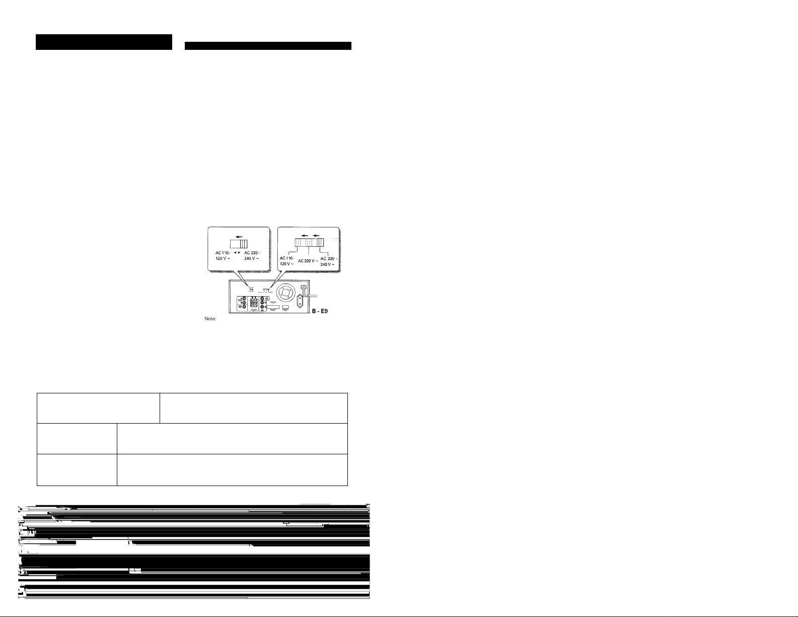
*Other countries............................110-120/220^30-240 Vswitchable
*AC voltage selection
The AC voltage selector switches Type A and Type B on the rear
panel are set to the voltage that prevails in the area to which the unit
is shipped. Before connecting the power cord to your AC outlet,
make sure that the setting position of these switches matche your
line voltage. If not, it must be set to your voltage in accordance with
the following direction.
Our warranty does not cover damage caused by excessive line
voltage due to improper setting of the AC voltage selector
switches.
Safety precautiom
WARNING : TO PREVENT FIRE OR ELECTRIC SHOCK, DO NOT EXPOSE THIS APPLIANCE TO RAIN
OR MOISTURE.
A
A
CAUTION: TO REDUCE THE RISK OF ELECTRIC SHOCK, DO NOT REMOVE COVER
(ORBACK).NOUSER-SERVICEABLEPARTSINSIDE,REFERSERVICINGTOQUALIFiED
SERVICE PERSONNEL.
THE LIGHTNING FLASH WITH ARROWHEAD SYMBOL, WITHIN AN EQUILATERAL TRIANGLE, IS
INTENDED TO ALERT THE USER TO THE PRESENCE OF UNINSULATED "DANGEROUS VOLTAGE"
WITHIN THE PRODUCT'S ENCLOSURE THAT MAY BE OF SUFFICIENT MAGNITUDE TO CONSTITUTE A
RISK OF ELECTRIC SHOCK TO PERSONS.
THE EXCLAMATION POINTWITHIN AN EQUILATERALTRIANGLE IS INTENDEDTO ALERTTHE USERTO
THE PRESENCE OF IMPORTANT OPERATING AND MAINTENANCE (SERVICING) INSTRUCTIONS IN THE
LITERATURE ACCOMPANYING THE APPLIANCE.
Page 3

Contents A Caution: Read this page carefully to ensure safe operation.
Before applying power
Before operation
Special feature
System connections
Controls and indicators
Operation of remote control unit
Clock adjustment
Sound adjustment functions
Playback of CD ^
Tape playback«^
Broadcast Reception ^
Operation with video components ^
30-Environmental sound systernm
Recording (Deck B only) -.. «n.-
CD edit recording m
Simplified tone adjustment
Presence playm
Convenient feature
Timer operation«i<^
Maintenance
In case of difficulty
Specifications
A Before applying power...........................................
ASafety precautions
FM DE-EMPHASIS/CHANNEL SPACE switch..
Inserting discs in magazine
Loading (unloading) the magazine
Playing tracks in order from track No. 1
Playback from desired track
Programming tracks in desired order
Repeated playback
Playback in a random order (Random playback)..
Playback of tape ..............................................................................
Relay playback.................................................................................
Skip search
Dash & play. One-program repeat playback, Rewind playback...
Receiving broadcast stations..........................................
Receiving radio station by specifying its frequency ..
Storing radio stations in memory (Station preset)
Playback of video tape
Recording of video souce ..
3D-Environmental sound play ...
Preparation for recording
Recording (Deck B only)
Copying tape (Tape dubbing)..
Select the type of edit recording
Program edit recording
Cross-fade edit recording
Timed edit recording.................................................
Al edit recording
Fade edit recording....................................................
Recording CD while listening to another source ..
Demonstration............................................ ........................................
Playing CD with optimum tone setting (Al AUTO)................................
Playing CD with enhanced presence effect (Al FOCUS)
Playing music with desired tone
Creating desired tone
Recording tape for playback on car stereo or headphone stereo ..
Enjoying music with feeling of presence (presence modes) ..
Presence effect plus Environmental sound
Recording music with presence effect..........................................
Controlling the depth of sound (DEPTH)
Adjustment and playback of DOLBY 3 STEREO
Dolby Surround adjustment
Operation of Dolby Surround playback
Easy karaoke singing (HIT MASTER)...............................................................................68U
Timer program reservation
Al TIMER operation....................................................................................
One-touch timer reservation. Sleep timer reservation
....
............................................
.....................................
....................................
.................................................
......................................................................................
.........
...........
............
................................
..............................................
.....................................................
.........................................
............................................
............................................................
..........................................................
...................
.
..........................
.................
......................
...........
.....................
..................................
......................................
..........................
.........................................
...........................................................
...........................................
.
^ r
5 J
Page 4
Before operation
The marking of products using lasers
(Except for some areas)
I cuss, I
I LASER PRODUCT |
The label Is attached to the rear panel and says that the compo
nent uses laser beams that have been classified as Class 1. It
means that the unit is utilizing laser beams that are of a weaker
class. There is no danger of hazardous radiation outside the unit.
Unit destination Shape of the AC outlet
U.S.A.,Canada
and U.S. Military
U.K.
Australia
Europe and
Other countries
o
o
C3>
FM DE-EMPHASIS/CHANNEL SPACE switch (Except for some areas)
The FM DE-EMPHASIS/CHANNEL SPACE switch on the rear panel is set to
the correct setting that prevails in the area to which the unit is shipped.
However, if the FM DE-EMPHASIS/CHANNEL SPACE setting is not matched
to the area where the unit is to be used; for instance, when you move from
area 1 to area 2 or vice versa, desired reception of AM/FM broadcasts is not
expected. In this case, change the FM DE-EMPHASIS/CHANNEL SPACE
setting in accordance with the area corresponding to the table. The FM DE
EMPHASIS is switched over at the same time.
• When changing the setting of the FM DE-EMPHASIS/CHANNEL SPACE
switch, first disconnect the power cord, then reset the channel space
switch, connect the power cord again, and turn the power on.
CAUTION:
Use of controls or adjustments or performance of proce
dures other than those specified herein may result in
hazardous radiation exposure.
In compliance with Federal Regulations, following are
reproductions of iables on, or inside the product relating
to laser product safety.
r" KENWOOD CORPORATION
2967-3, ISHIKAWA-CHO,
HACHIOJI-SHI,
TOKYO, JAPAN
KENWOOD CORP. CERTIFIES THIS EQUIPMENT
CONFORMS TO DHHS REGULATIONS NO. 21 CFR
1040. 10, CHAPTER I, SUBCHAPTER J.
Location: Back Panel
Area
U.S.A., Canada,
and South Ameri
1
can countries
Other countries
2
CHANNEL
SPACE freq.
FM;100kHz
AM: 10kHz
FM: 50kHz
AM: 9kHz
DE-EMPHASIS
CHANNEL SPACE
O
1% iP I 75lis
FM
DE-EMPHASIS
75p,s
50ps
Page 5

Special feature
SlJ’^CASi
The DPSS (Direct Program Search System) allows you to play a
cassette tape with a variety of playback functions tike a CD.
Playing tunes by skipping some.
Playing a single tune repeatedly.
Rewinding a tape and playing from the beginning.
Playing a tape by skipping blanks between tunes.
Different sounds of different sources can be played through the
main and omni speakers.
Play the provided Sound Enhancement CD through the OMNI speak
ers (optional) and play music through the main speakers, and you'll
experience a completely new world of music. Naturally, any other
combinations of sound sources are possible.
еядрнЩг:
lliljlliilllll
■^EQUALIZER
^ nMER
iiipplifiedCDrpconliiig
СшушШ timer (unations
Various CD editing & recording features are available for
selection according to the tape you want.
Fade edit recording: Recording CD tracks sequentially from No. 1.
Program edit recording:Recording desired CD tracks in desired or
Timed edit recording: Recording CD tracks within the specified
Al edit recording: Recording all CD tracks even in case the
X.FADE (Cross-fade) edit recording:
The reproduced sound can be played with infinite purity without
any additional manipulation o f the tone.
The improved graphic equalizer feature allows automatic curve
setting with Al (Artificial Intelligence) as well as user's selection
or even creation of desired curves. Up to 5 user-created curves
can he stored in preset memory.
□□itioiBYsuRiiouiuDi playback is a matter of course. In addition,
sound can be reproduced in KENWOOD original sound fields and
the depth of sound can be adjusted as desired. You can enjoy
music in a sound field you like.
In addition to the possibiiity of storing up to 4 timer programs in
memory, the following functions are avaiiable.
Al TIMER!: When the power is turned ON by the timer, the
Al TIMER2: When the power is turned ON by the timer, two
Sleep timer: Useful when you want to go asleep while listen
One-touch timer: The power can be turned ON at an approximate
der.
tape length so that no track is interrupted in
the middle,
total playing time exceeds the total record
ing time of tape.
Recording by overlapping the beginnings
and endings of the CD tracks.
sound increases gradually.
CD tracks are played first, then radio is received
after it.
ing to music.
time, without the need of the fine time adjustment
operations.
Page 6
System connections
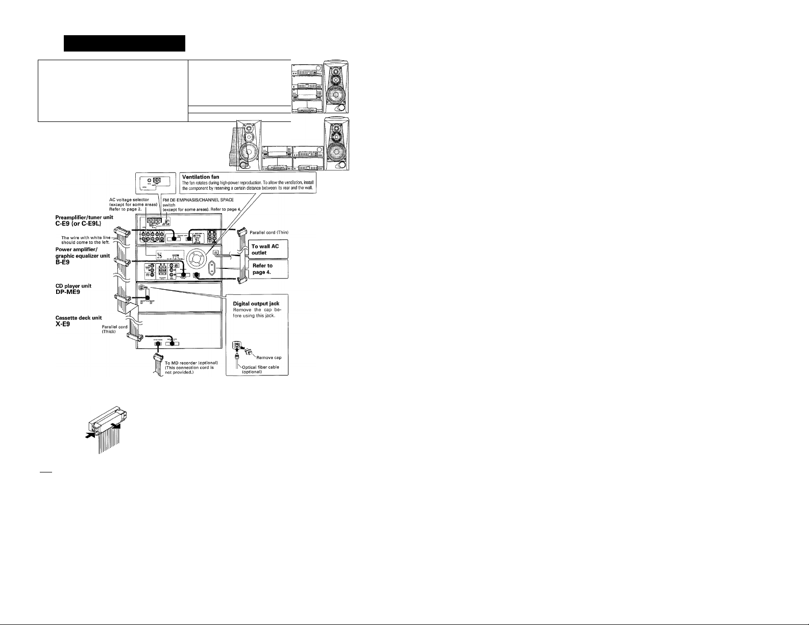
Do not plug the power cord into the power outlet until
all of the required connections have been made.
m When arranging the system units in a vertical, stacked configu
ration, observe the stacking order indicated in the system con
nection diagram below.
• In case an associated system component is connected, also
read the instruction manual of the component.
• Align the front panels of the unit flush.
When arranging the system in a horizontal configuration, be sure to
place the preampiifier/tuner unit + power ampiifier/graphic equalizer
unit on the right side of the CD player unit + cassette deck unit.
(For U.K. and Europe)
1
Connection oiparallffXmi^
• When connecting the parallel cord, insert the plug straight into
the connector until it clicks to lock them securely.
> When connecting the parallel cord, the wire with white line should
come to the left side end.
I When disconnecting the parallel cord, push in the two sides of
the plug and pull it straight out.
X
1. Be sure to insert all connection cords securely. If their connections are imperfect, the sound may not produced or noise may
I Notes I
interfere.
2. Before plugging or unplugging a connection cord, be sure to unplug the power cord from the wall AC outlet. If connection cords are
plugged or unplugged with the power cord left plugged in, malfunction or damage may result.
3. Do not connect up a power source whitch is larger than that indicated on the socket at rear of the unit.
Uiiiiiiiiii'P
Page 7
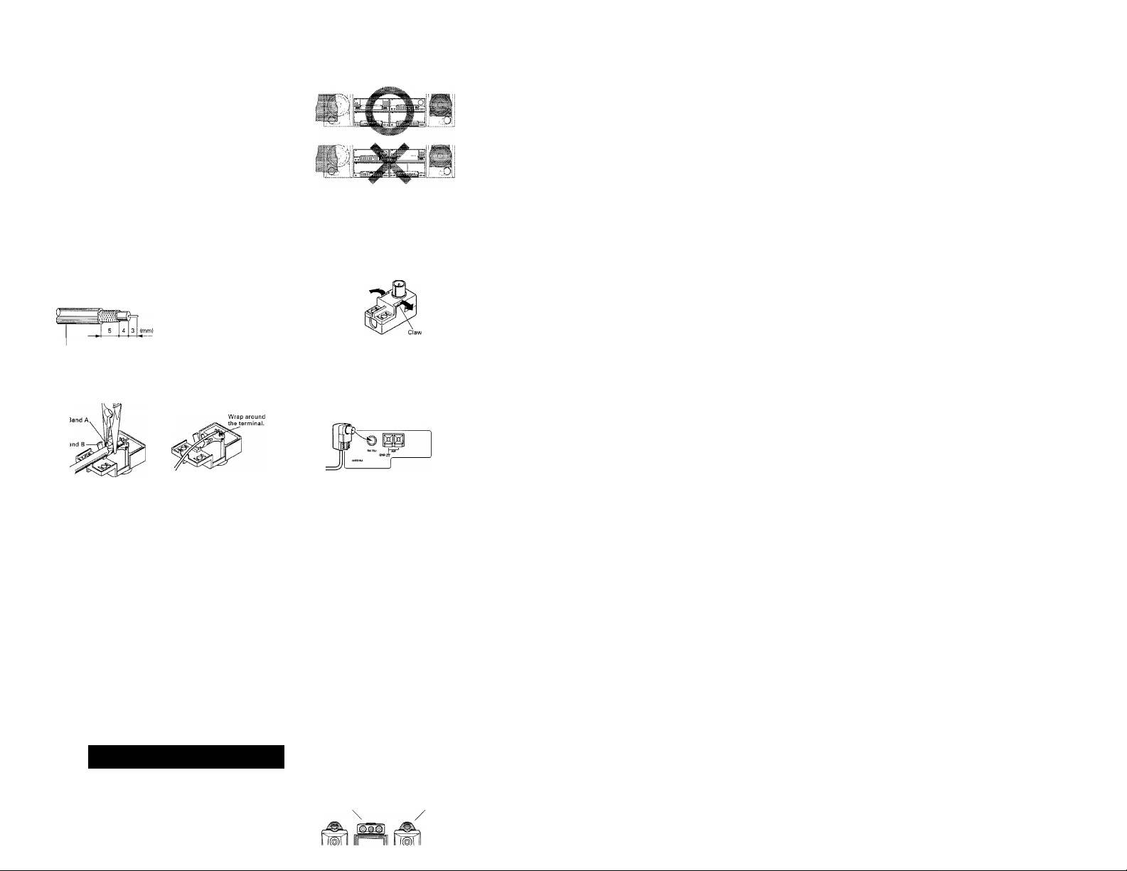
Caution
When installing the system components in a horizontal
cofiguration, place the preamplifier/tuner unit (C-E9) and
power amplifier/graphic equalizer unit (B-E9) to the right of
the CD player unit (DP-ME9) and cassette deck unit (X-E9) as
shown in the connection diagram.
Do not place the CD player and cassette deck to the right of
the power amplifier/graphic equalizer unit, for this will lead
to overheating or malfunction.
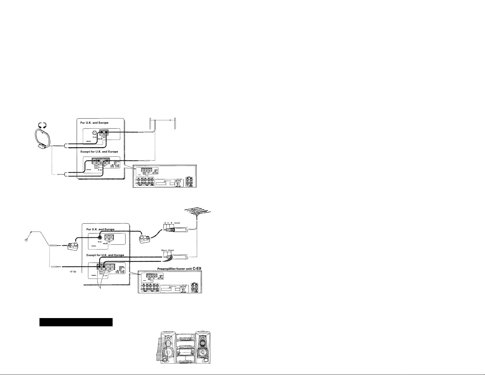
Connection of antenna adapter (U,K and Europe only)
0 Strip the cable coating.
When coaxial cable is used When the provided simplified
antenna is used
('2) Open the antenna adaptor.
RG-6 (5C-2V) or RG-59 (3C-2V)
(3) Attach the cable and close the cover.
When coaxial cable is used When the provided simplified
Insert the cable into the slit on
the clip. Fasten bands A and B
using a pair of pliers.
antenna is used
Insert the antenna cord tip into
the slit on the hardware and
wrap the cord around it.
Optical fiber cable connection
The digital OPTICAL output is designed for use in the connec
tion with an MD recorder (optionally available). The digital
signal transmission allows you to record the CD sound on MD
without spoiling the high sound quaiity. This jack can also be
connected to an amplifier equipped with a digital optical
input (optical fiber).
Open the claws with the fingers to release
the lock and pull out the cover.
® Connect the adaptor to the antenna terminal.
• When using an optical fiber cable to connect this unit to a MD
recorder or digital amplifier, insert the plug straight into the jack
until a snap sound is heard.
• Be careful not to bend, coil or bundle the optical fiber cable.
• Optical fiber cables available in audio accessory stores may not
always be able to be used with this unit. If your cable cannot be
used with this unit, consult the store from which you purchased
the cable or your nearest dealer.
Connection of speakers
Arrangement of speakers
Center speaker (optional) Omni-speakers (optional)
Page 8
Connection method
© Push the lever. ® Insert cord. © Return the lever.
Preamplifier/tuner unit C-E9
rO
ii^ ^ ^ ^ ^
Connection of AM antenna
Connection of AM loop antenna
The provided antenna is for indoor use. Place it in a position as far as
possible from this system, TV, speaker cords and power cord and set
to the orientation which provides the best reception condition.
Connection of AM outdoor antenna
If the reception condition is poor with the loop antenna alone, connect
a vinyl coated wire of more than 6 m (20 ft) and extend it outdoors
while leaving the loop antenna connected.
Connectiol) of FM entejjim
Connection of FM simplified antenna
The provided antenna is designed for temporary indoor use. For stable
reception, it is recommended to install an outdoor antenna as soon as
possible. Once an outdoor antenna is connected, remove the indoor
antenna.
® Remove the coating from the c(
section and twist conductors.
® Find the location providing the best
receiving condition.
(3) Fix the antenna there.
When a T-shaped, FM indoor antenna (300 £1) which is marketed in audio stores is used, connect
it to these terminals. (In this case, disconnect the provided FM simplified antenna.)
Connection of FM outdoor antenna
Lead the antenna wire indoors using a 75 coaxial cable and connect
it to the FM 75 £2 connector.
V
Preamplifier/tuner unit C-E9
System connections
Do not plug the power cord into the power outlet until all of the required connections have been made.
• When arranging the system units in a vertical, stacked configu
ration, observe the stacking order indicated in the system con
nection diagram below.
• In case an associated system component is connected, also
read the instruction manual of the component
Page 9
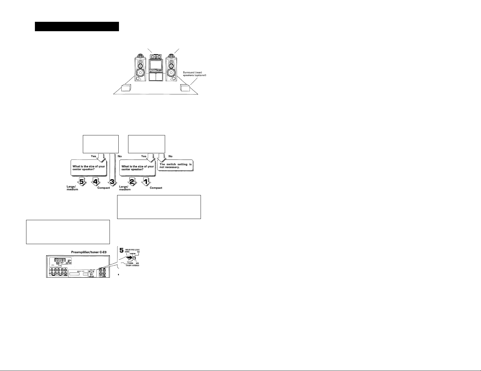
Connection of speakers
Arrangement of speakers
Setting the center mode
By connecting the optional rear speakers and/or cen
ter speaker, the music can be enjoyed with the pres
ence effects of DOLBY 3 STEREO and DOLBY PRO
LOGIC. Before using this mode, set the center mode
switch referring to below.
Do you have the cen Do you have the center
ter speaker?
.
DOLBY PRO LOGIC
OM I
DOLBY 3 STEREO can be enjoyed
DOLBY 3 STEREO
2 COLBY PRO LOGIC
1 PHANTOM 1
DOLBY 3 STEREO
in NORMAL mode.
DOLBY 3 STEREO can be enjoyed
in WIDE mode.
Center speaker (optional) Omni-speakers (optional)
START!
Do you have the
rear speakers?
speaker?
-
_____________________
O DOLBY PRO LOGIC
NORMAL WIDE
DOL^J ^7°
DOLBY PRO LOGIC
If you cannot tell whether your center
speaker is of the large/medium or com
pact size, compare both settings and
select the one you like better.
DOLBY PRO LOGIC can be en
joyed in PHANTOM mode.
DOLBY PRO LOGIC and DOLBY 3
STEREO can be enjoyed in NOR
MAL mode.
DOLBY PRO LOGIC and DOLBY 3
STEREO can be enjoyed in WIDE
mode.
• The set contents may sometimes be initialized to the original set
ting after the power cord is unplugged and plugged again.
Page 10
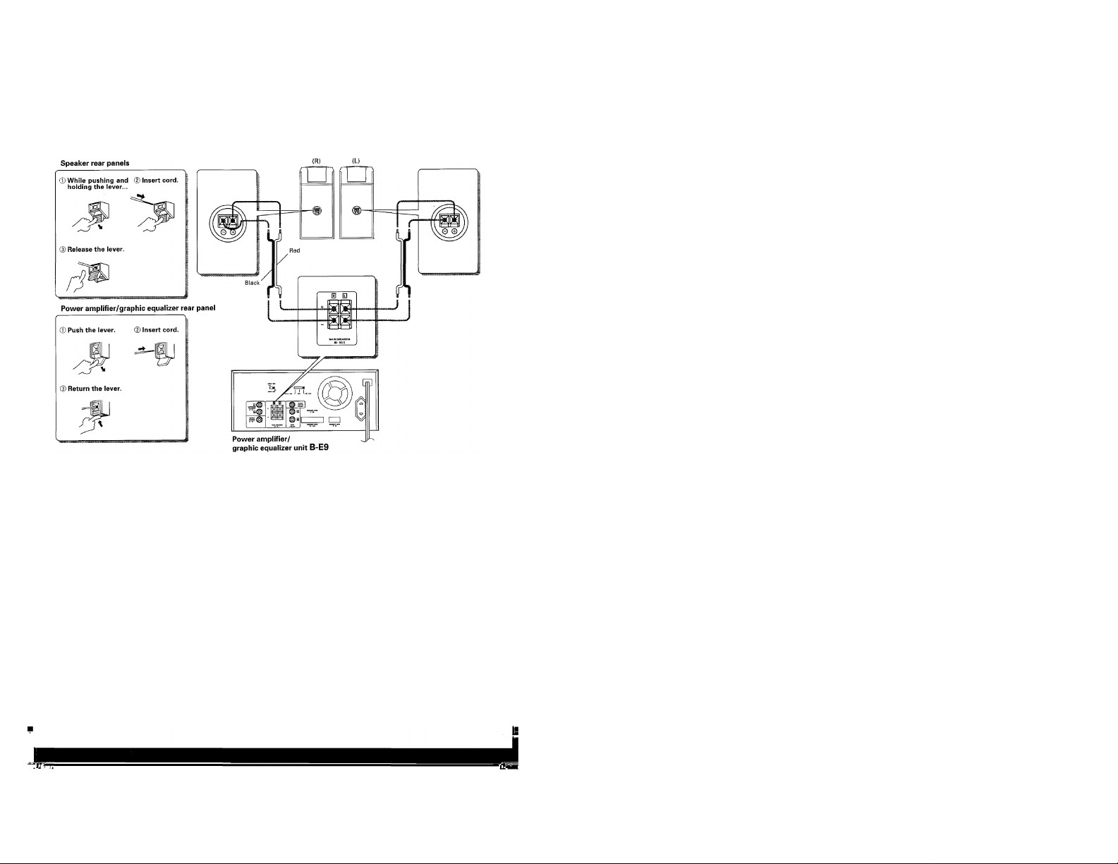
Connection of the front speakers
• Never short-circuit the + and - speaker cords.
• If the left and right speaker connections or the + and - polarity are
inverted, the sound will be unnatural with unclear positioning of
musical instruments, etc. Be sure to connect them without mis
take.
Page 11

Connection of optional speakers
Super woofer
SW-500 (optional)
• Set the Volume controls of the omni-speakers (OMNI-A5) to the
center positions.
• For the combination of the omni-speakers (OMNI-A5) with the front
speakers, refer to the instruction manual provided with the OMNI-
A5.
Page 12
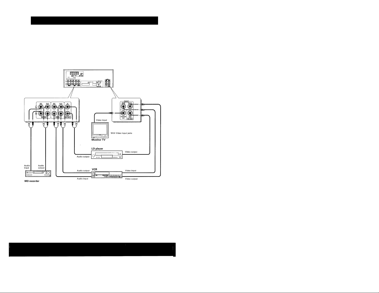
Connection of Audio/Visual components (optional)
• Connection cords are not supplied with this system.
I Any of the following video equipment can be connected in
place of the LD player.
• DBS tuner
• Video camera
• Video recorder
( A DAT recorder can also be connected in place of the MD (Mini
Disc) recorder.
Preampiifier/tuner unit C-E9
Connection of the front speakers
Page 13
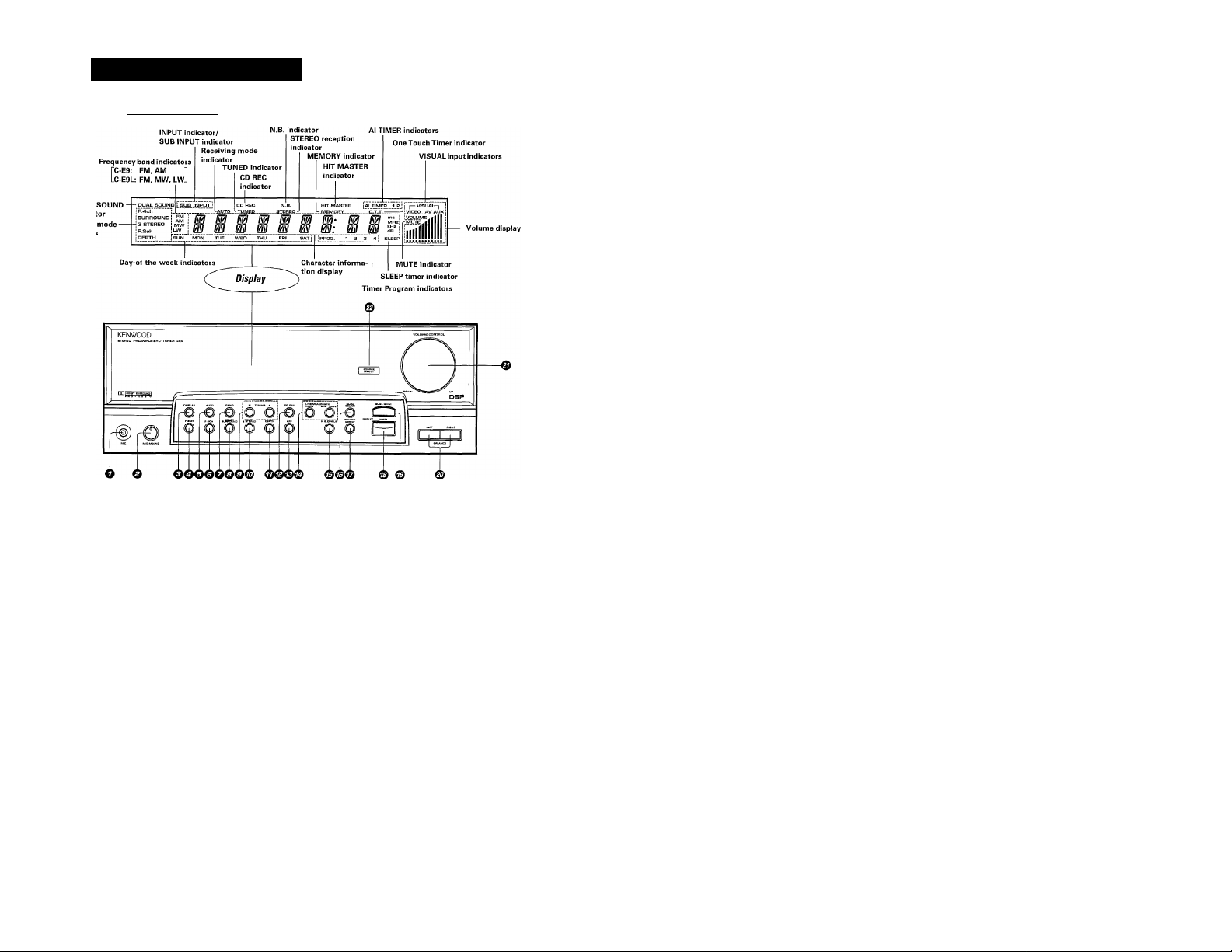
Controls and indicators
Preamplifier/tuner unit
MIC jack
MIC MIXING control
Turn to adjust the microphone input volume.
DISPLAY key
Press to change over the display contents.
F.2CH key
AUTO key
Press to receive stations in auto tuning mode.
F.4CH key
BAND key
Press to select the required frequency band.
DOLBY SURROUND key
TUNING {▼, ▲) keys
Press to select the station to be received.
DOLBY 3 STEREO key
DEPTH key
Press to adjust the feeling of depth of the sound.
CD REC key
Press to record a CD while playing another source.
OFF key
Press to switch the surround and presence modes OFF.
CD player unit
EDIT mode indicators
DAMrtrtnii
___________
© LINEAR ACOUSTIC {MAIN, SUB-OMNI) keys
Press to adjust the volume balance between the main speakers
and OMNI speakers (optional).
© N.B.CIRCUIT key
Press to adjust the bass sound.
© DUAL SOUND key
Press for environmental sound play.
© SOURCE DIRECT key -gg
Press to play music without additional tone manipulation.
© MAIN INPUT key
Press to seiect the component to be played.
© SUB-OMNMNPUT key
Press to select the component to be played through the OMNI
speakers (optional) for environmental sound play.
® BALANCE (LEFT, RIGHT) keys
Press to adjust the volume balance between the left and right
speakers.
© VOLUME CONTROL knob
© SOURCE DIRECT indicator
Lights when the SOURCE DIRECT function is ON.
I
Page 14
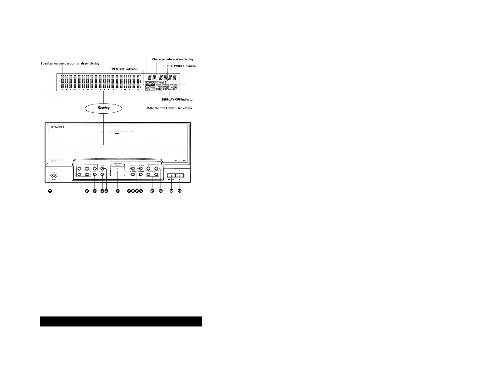
^ PmumplHier/graphic equalizar unit
REC MODE indicators
' EQ.ON indicator
O PHONES jack
© Preset keys (1 to 5) - gg
© FLAT key -gg
Press to make the equalizer curve flat.
O EQ.MEIVIO key -gg
Press to store an equalizer pattern in memory.
© R/M key -gg
Press to switch the equalizer curves to be recalled between Ref
erence and Manual curves.
© POWER key -gg
Press to turn the power ON/OFF.
© DISPLAY key .g^
Each press changes the display contents in order from grapmc
equalizer to spectrum analyzer, demonstration and display OFF.
© EQ.EFFECTkey
Press to switch the equalizer effect ON/OFF.
Connection of Audio/Visual components (optional)
» Connection cords are not supplied with this system,
t Any of the following video equipment can be connected in
place of the LD player.
• DBS tuner
• Video camera
• Video recorder
t A DAT recorder can also be connected in place of the MD (Mini
rprordpr
© CHARACTER key * *gg
Each press changes over the spectrum analyzer display modes.
® REC MODE key *gg
Press when recording a tape to be played on a car stereo or head
phone stereo.
© FREQUENCY (◄.►) keys *gg
Press to select the frequencies to be adjusted.
© EQ.LEVEL
© S.W.EFFECT key ->gg
© Alkey
(T, A)
Press to adjust the equalizer curve level.
Press to switch the effect of the super woofer (optional) ON/OFF.
Press to set the suitable equalizer curve for each CD automati
cally.
key »gQ
Page 15
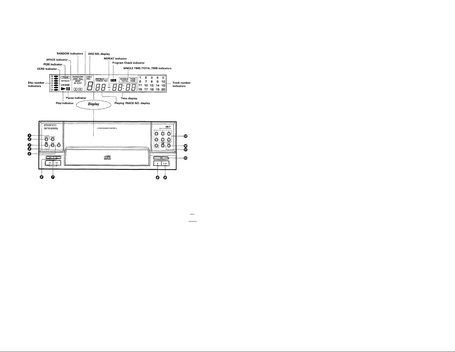
CD player unit
EDIT mode indicators
O RANDOM key
Press to play tracks in a random order.
© REPEAT key
Press for repeated playback.
© EDIT MODE key
Press to select the edit recording mode.
O SPACE key
Press in PGM mode to create a non-recorded space of a few sec- ©
onds between recorded tracks automatically. 0
© TIME key
Press to switch the time display mode.
-ES
*E2
-El
Search keys
©
Press to move the played position of disc at high speed.
Skip keys -*
©
Press to skip to the beginning of another track.
Stop key
©
Play/pause key -
©
0
DOOR key .>ggl
P. OPEIM/CLOSE (Plus-1 tray open/close) key *^0
M.EJECT (Magazine eject) key -[pTSi]
0
Disc selector keys (1 to 6, P) -*
Page 16
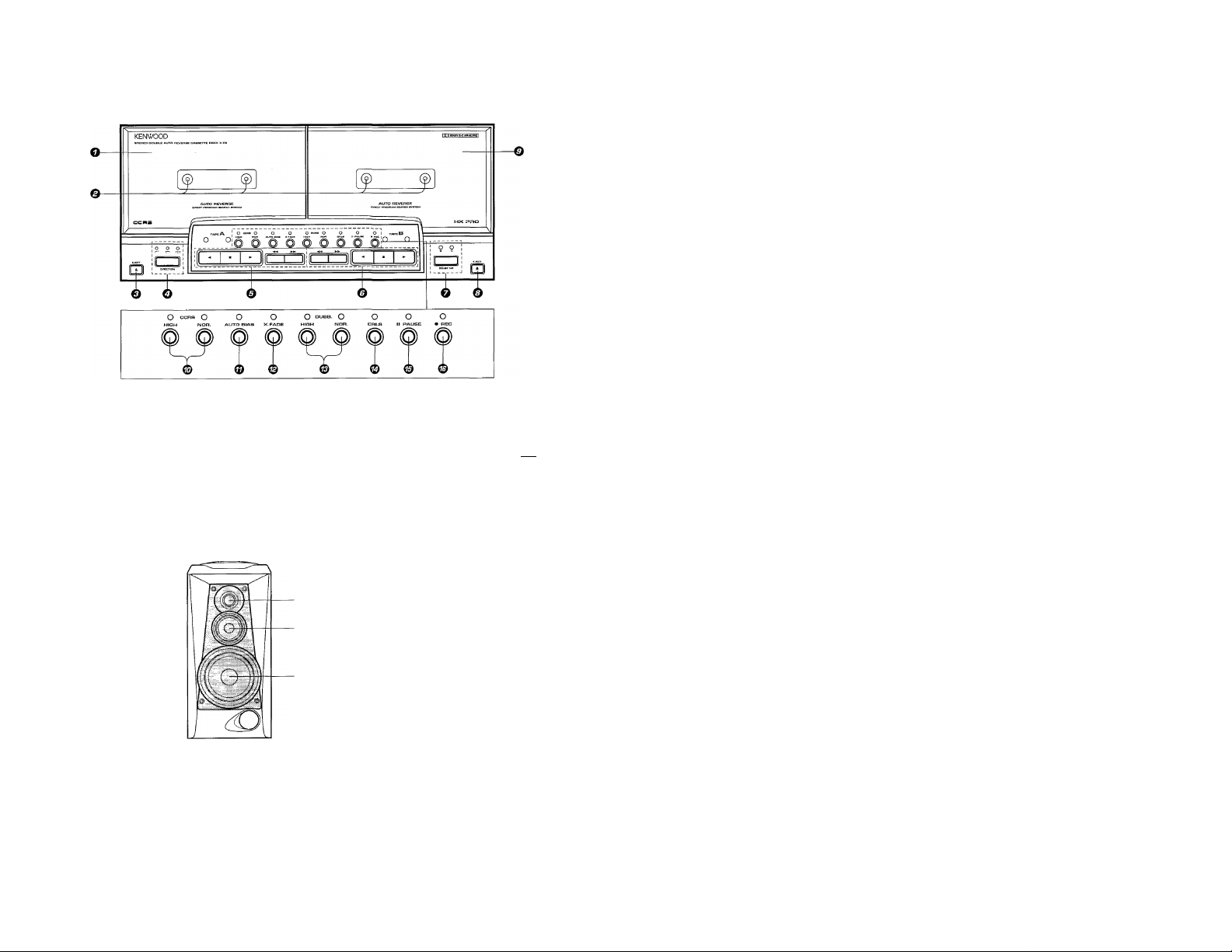
O Deck A cassette holder
© Tape running indicators
© Deck A eject key
O DIRECTION key/indicator
Press to switch over the play modes.
© Deck A operation keys
► Play keys/indicators
■ Stop key
►► Fast Forward key
Rewind key
Speaker unit.
Model: LS-E9
Cabinet type: Bass-reflex type
(Figure shows the R CH speaker.)
© Deck B operation keys
► Play keys/indicators
■ Stop key
►► Fast Forward key
Rewind key
O DOLBY NR key/indicator -
© Deck B eject key
© Deck B cassette holder
0 CCRS keys (HIGH, NOR.)/indicators
Press to start recording after having set the
optimum recording level for the CD and the
optimum recording bias for the tape auto
matically.
Tweeter
(for medium and high frequencies)
Mid-range unit
(for medium frequencies)
Woofer
(for low frequencies)
© AUTO BIAS key/indicator
Press to set the tape recording bias auto
matically.
© X.FADE (Cross-fade) key/indicator
Press to create a tape with continuous
music by fading in the beginning and fad
ing out the end of every tune. .>¡^47]
0 DUBB keys (HIGH, NOR.I/indicators
Press for dubbing between tapes.
© CRLS key/indicator -
Press to set the optimum recording level
automatically.
0 Pause key/indicator
© Record key/indicator -
jj EpwPF mpiifier/graphic equalizer unit
REC MODE indicators
Page 17
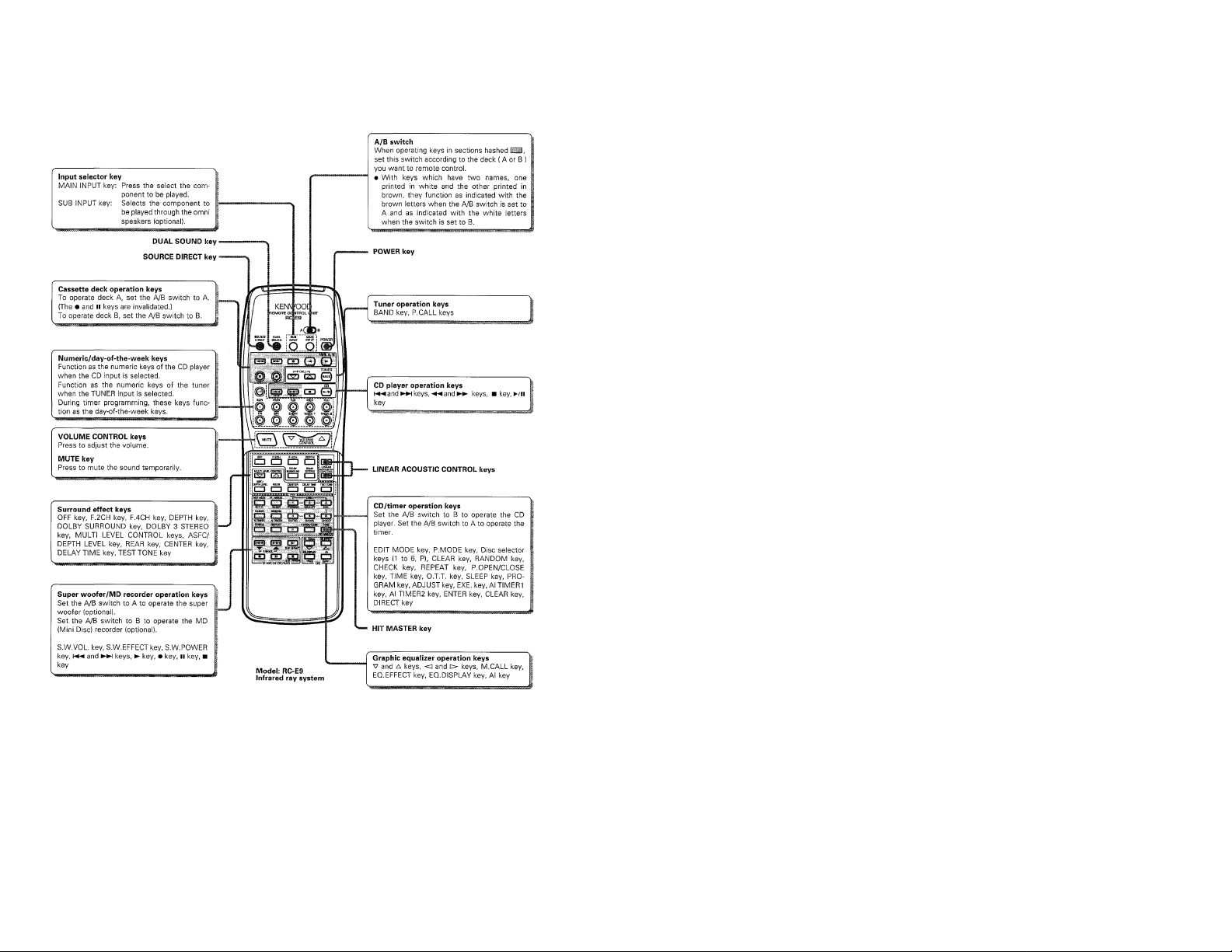
Remote control unit
Page 18
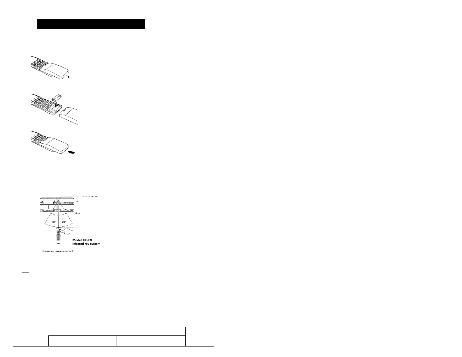
Operation of remote control unit
Loading batteries
f Remove the cover.
2 Insert batteries.
^ Close the cover.
» Insert two R03 ("AAA"-size) batteries following the polarity indica
tions.
Operation
After plugging the power cord of the amplifier, press the
POWER key of the remote control unit to turn the power of
the system ON. When the power is turned ON, press the key
of the function to be operated.
> When pressing more than one remote control keys successively,
press the keys securely by leaving an interval of 1 second or more
between keys.
In this manual, the remote control unit is illustrated with Its cover
omitted. This is simply for the convenience of explanation.
1. The provided batteries are intended for use in operation checking, and their service life may be short.
I Notes I
2. When the remote controllable distance becomes short, replace both of the batteries with new ones,
3. If direct sunlight or the light of a high- frequency fluorescent lamp {inverter type, etc.) is incident to the remote sensor, malfunction may
occur. In such a case, change the installation position to avoid malfunction.
fs ^ossette dec^jggit
KENWOOD
O
-----
UD-95a (En)
—o
Page 19
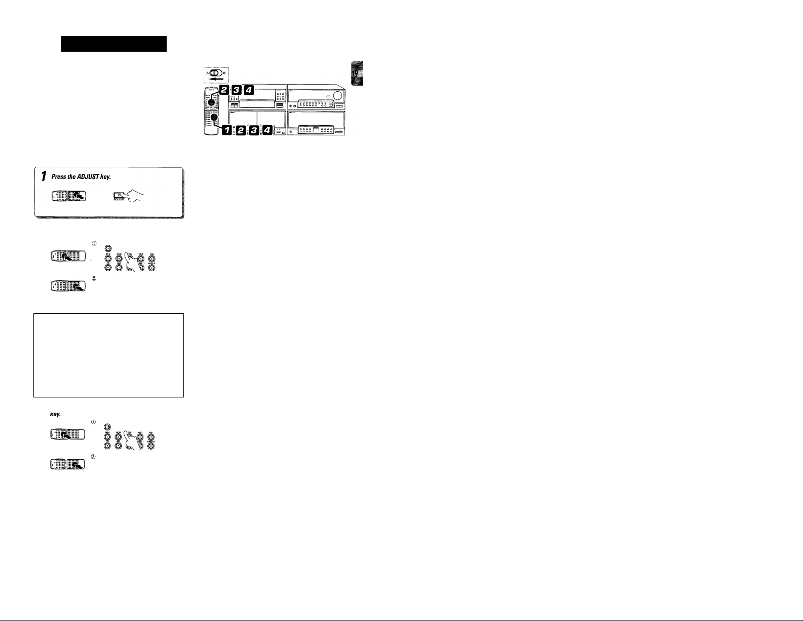
Clock adjustment
The preamplifier/tuner unit incorporates a clock function. Be
sure to adjust the correct time before using the timer func
tion.
2 Eater the year and press the ENTER key.
ENTER
---
O Enter the month then the date, and press the EN-
O TER key.
Press numeric keys in the following order.
To enter 1994 ... [Il.d],®.®
■ If you make a mistake, press the CLEAR key and enter the track No.
from the beginning.
UMl
\ ^ Am '41P M
J § ®
3 SO
^ Enter the hour and minute and press the ENTER
Press numeric keys in the following order.
To enter March 7 ... [o],[i],[o],a
To enter December 30 ... [l], [s], [D, 0
• If you make a mistake, press the CLEAR key and enter the track No,
from the beginning.
Press numeric keys in the following order.
To enter 9;05AM [^, [9], , [5]
To enter 4:50PM 0, [E, [5]. (□]
• If you make a mistake, press the CLEAR key and enter the track No.
from the beginning.
• To adjust correct time, press the ENTER key at the same moment
as a time announcement.
• The time display blinks after a power failure or when the power cord
has been unplugged from the AC outlet and plugged again. In such
a case, adjust the clock again.
Page 20
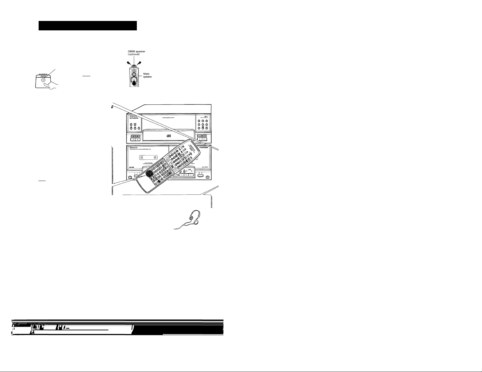
Sound adjustment functions
Power ON/OFF
Press the POWER key of the power amplifier/graphic equal
izer unit.
STAND BY indicator
POWER
fr
• The power of the overall system can be turned ON/OFF by
pressing the POWER key of power amplifier/graphic equalizer
unit.
Enhanced bass entertainment with super woofer (op
tional)
® Press the S.W.EFFECT key.
a^TTT)b
Remote control unit
{Point remote control unit to the main system.)
(D Adjust the super woofer volume.
Remote control u
Adjusting the volume balance between main and OMNI speakers (optional)
The balance between the main speaker vol
ume and OMNI speaker volume can be var
ied freely. This allows you to enjoy various
sounds according to the ambience of the
music being played or to your personal
taste.
• Press one of the LINEAR ACOUSTIC CON
TROL keys to display the current balance set
ting, Pressing the keys while the setting is
displayed will change the setting.
• Pressing and holding the MAIN or SUB-OMNI
key alone allows to play the sound through the
main or Omni speakers alone.
• Set the Volume controls of the omni speakers
to the center positions.
Listening through headphones
® Insert the headphone plug into the PHONES jack.
To increase volui
В
(Point remote control
unit to the super woofer.)
I Once the super woofer volume has been set, it will increase or
decrease according to the VOLUME adjustment.
STAND BY mode of POWER switch
When the power cord is plugged into an AC outlet, the STAND BY indicator lights regardless of the power ON/OFF setting. This is because, even
when the power is set to OFF, a small amount of power is supplied to the system to back up the memory. This status is called the standby mode
of the system. While the STAND BY indicator is lit, the power can also be turned ON/OFF from the remote control unit.
It can also be adjusted with
the volume control provided
on the super woofer.
I The sounds from all speakers are cut off,
I The sound output through the OMNI speakers (optional) are
not reproduced through the headphones.
(|) Adjust the volume.
0 to reduce the volume before removing the plug from
the jack.
Page 21
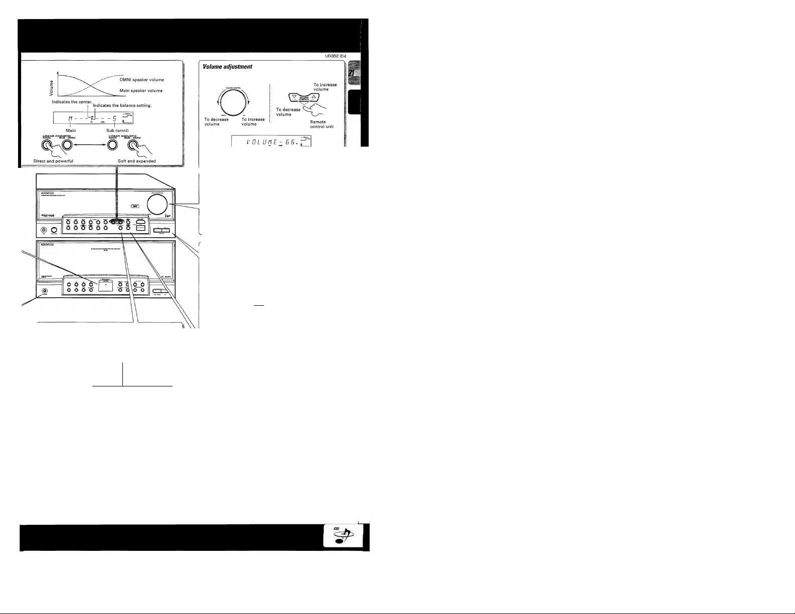
Volume display
Muting the sound temporarily
Remote control unit only
Blinks
c 1
I Press again to resume the original volume.
I
Adjusting the ieft/right volume balance
Indicates the center.
To decrease Right volume jj^ j |j
Indicates the balance setting.
I
To decrease Left volume
Compensation of bass sound
N.B.CIRCUIT: Natural Bass CIRCUIT
Every time the button is pressed,
mode changes as follows.
WJ / /
: (Weak effect)
WJ
: (Strong effect)
WJ -- /
: (Attenuated bass)
Wi UFF
; (N.B. circuit disabled)
®
W.5
Playing sound with higher purity
When the SOURCE DIRECT function is
switched ON, the played signal takes the sim
plest path without passing through the balance
control circuitry and audio processing circuitry
such as the DSP, so the sound can be played
with an improved purity.
HI RE r T OR
• Normally, set to the WJ OFF position.
• Adjust the control to obtain as natural bass sound a
Input selection on the preamplifier/tuner unit and easy operation function
By simply changing the input source selection (CD, TUNER TAPE, etc.), the selected source component starts to play automatically. Inversely,
playing a source component switches the input selection of the preamplifier/tuner unit automatically.
These operations are also possible from the remote control unit. When the power of the system is turned ON, the source which has been played
the last time the power is turned OFF is played automatically (CD, TUNER, etc.).
* The easy operation function is deactivated during environmental sound play (with which different sounds are output through the main speakers
and optional omni speakers).
• When the SOURCE DIRECT is ON, the SOURCE DIRECT indi
cators on the front panel lights.
• Press the key again to cancel the SOURCE DIRECT.
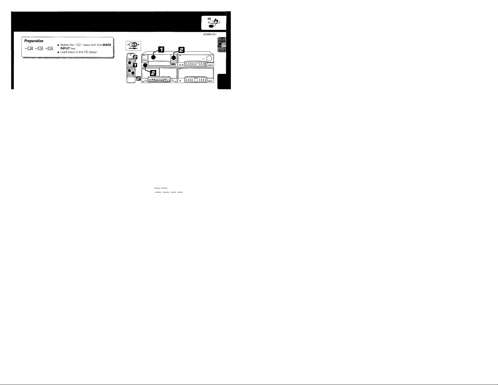
Preparation
£9l
Page 22
Playback of CD
I
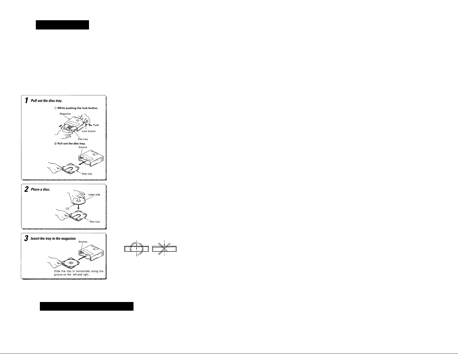
Inserting discs in magazine
Sound adjustment functions
Power ON/OFF
Press the POWER key of the power amplifier/graphic equal
izer unit.
» Ordinary CD single (8 cm) disc adapter sold in audio stores cannot
be used with this unit. In case a CD single (8 cm) disc is played, use
the optional CD single disc magazine "CDM-608".
Disc tray Disc tray
• When inserting discs in magazine, they must always be placed on
the disc trays.
• Always insert 6 disc trays in a magazine regardless of whether
discs are placed on them or not.
• Hold the magazine horizontally when transporting it.
Adjusting the volume balance between main and
OMNI speakers (optional}
OMNI speaker umeand OMNI speaker volume can be var-
(optional) ¡ed freely. This allows you to enjoy various
^ I ^ music being played or to your personal
The balance between the main speaker vol-
sounds according to the ambience of the
Page 23
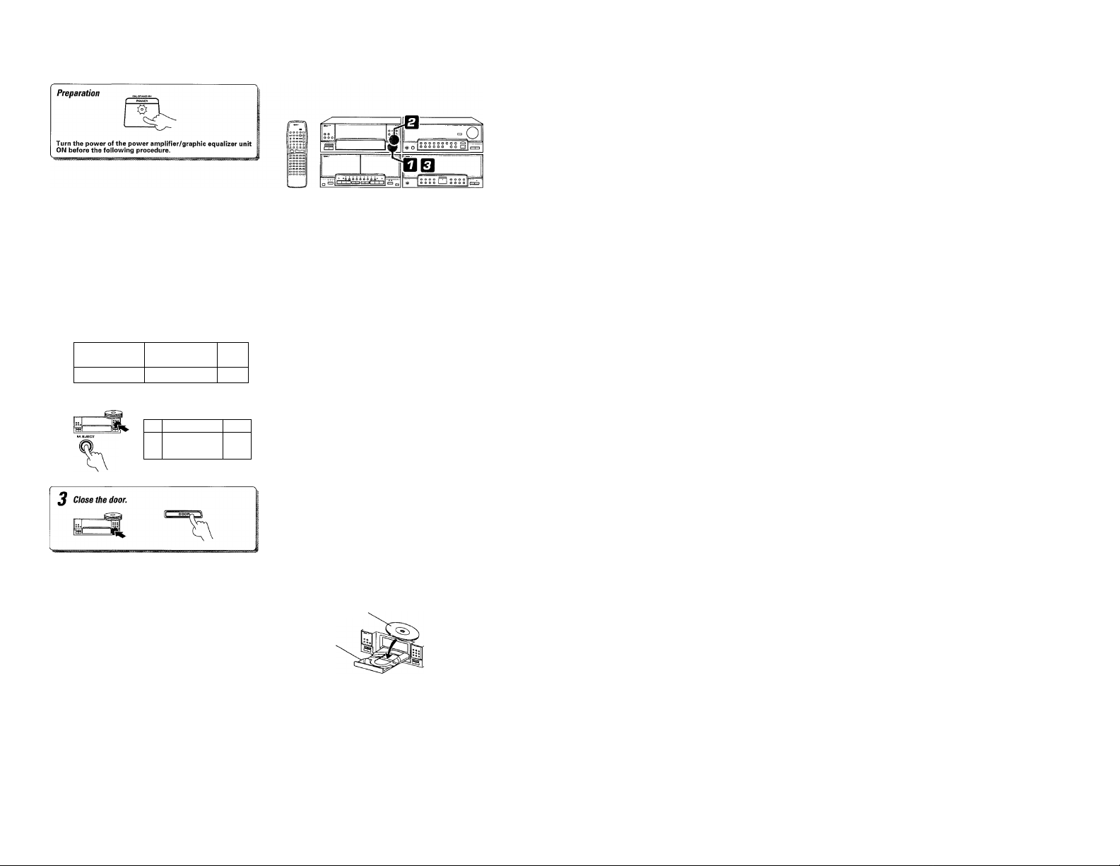
Loading (unloading) the magazine
f Open the door.
• When the M.EJECT key is pressed, the door opens and the maga
zine is ejected.
^ Load (or unload) the magazine.
Loading Magazine
Unloading
Press the M.EJECT key.
Hold the center of magazine and pull o
Inserting a disc on Plus-1 tray
© Open the Plus-1 tray.
@ Place a disc.
® Close the Plus-1 tray.
^ 0 O 0
Push in until
it clicks.
/
» The door will open and the Plus-1 tray will come out.
I Place the disc properly along the groove on the tray.
(Do not place obliquely, or malfunction may occur.)
• The Plus-1 tray and the door will close.
Label side v
Page 24
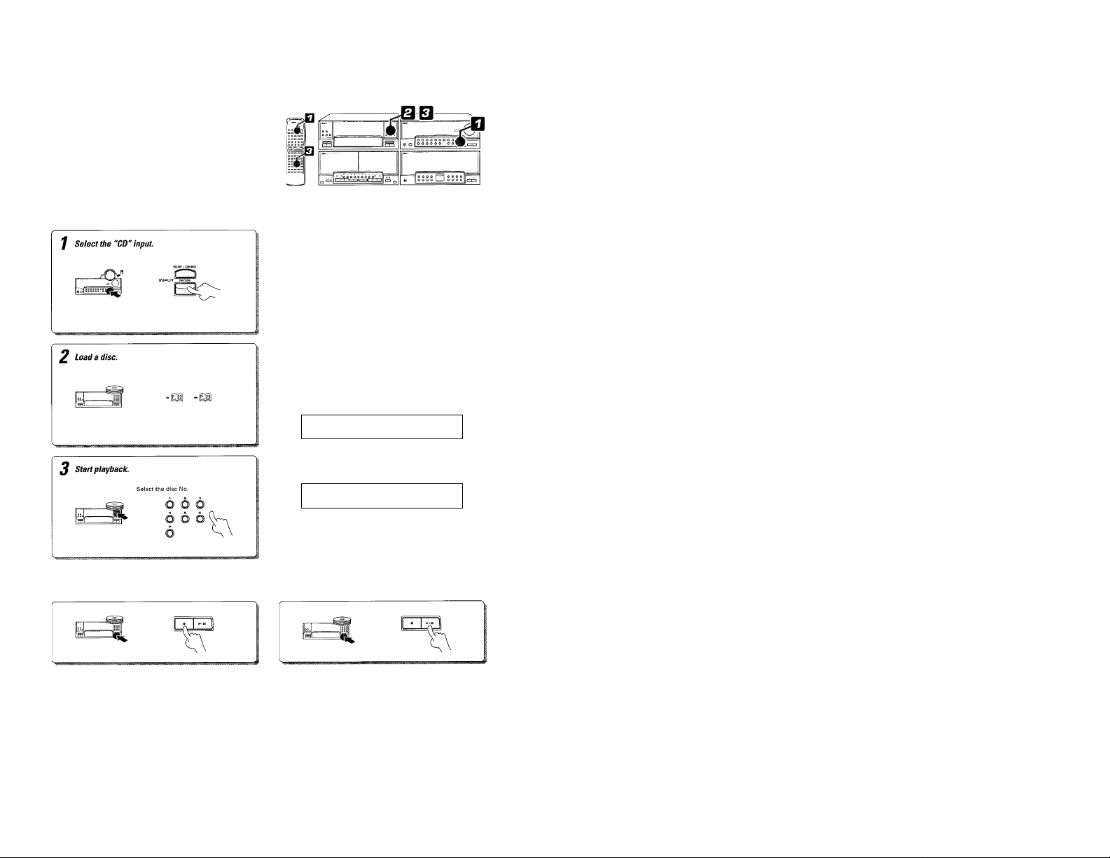
Use the following procedure to play CDs in the original order
of tracks from track IMo. 1.
ill
I
Playing tracks in order from track No. 1
• When playing only one disc, remove the magazine and place the
Each press changes the inputs as follows,
LU
® TUNER (frequency display) "CD" should be displayed.
(D JRPE I
0 nu/sfu
® PIUEU
■ ® Ri' RUX
disc only on the Pius-1 tray.
All of the disc indicators light regardiess of whether
there are discs on the disc trays or not.
n ■ n n 11 12 13 14 15
U n 1
U ■ U U
1
U 1
16 17 18 19 20
To stop playback
The indicator goes off if the
selected disc is n
• Playback starts from the selected disc and continues in order of
disc Nos.
• If the ►/!! key is pressed without selecting a disc, discs will be
played automatically in the following
order; P-+1-^2-»-3-^4-^5-*6. (P: Plus-1 tray)
To pause playback
I Each press pauses and plays the CD alternately.
lot present.
1
n 1
►
LI u 1
— 1^345
Page 25
Playback from desired track
J Check that the "PGM" indicator is not lit.
The "PGM" gose off.
Select the desired track.
(p Select the disc No.
odd
6 6 6
6
' (2) Select the track No.
Skipping tracks
To skip backward
Searching
Backward search
To skip forward
Q3
Forward search
» If the "PGM" indicator is lit, press the P.MODE key of the rennote
control unit to turn it off.
• By using the remote control unit, the desired track No. can be speci
fied with numeric keys.
Press the numeric keys as shown below....
To enter track No. 23: |+10|.|+10|. [Tl
To select track No. 40: l+10|, l+10|, k10|, i+io],
• Playback starts from the selected track and continues on the sub
sequent tracks.
• If a track number which does not exist on the disc is selected while
the tray is open, the last track in the disc will be played.
• Once the tray has been closed or disc has started to play, it is not
possible to select a disc which does not exist on the disc.
Set the A/B switch to B when operating this function with
the remote control unit.
i When the key is pressed once during playback, the track being
played will be played from the beginning.
Set the A/B switch to A when operating this function with
the remote control unit.
• Playback starts from the position where the key is released.
Page 26
i Use the following procedure to select desired tracks (up to 32
tracks) from up to 7 discs and program them in the desired
M
order.
Preparation ---------- --- --- -------------- --- ----------------- --- -------------
• Select the "CD" input with the MAIN
, [_Qg(J (jig(.g ¡p Q plgyeT.
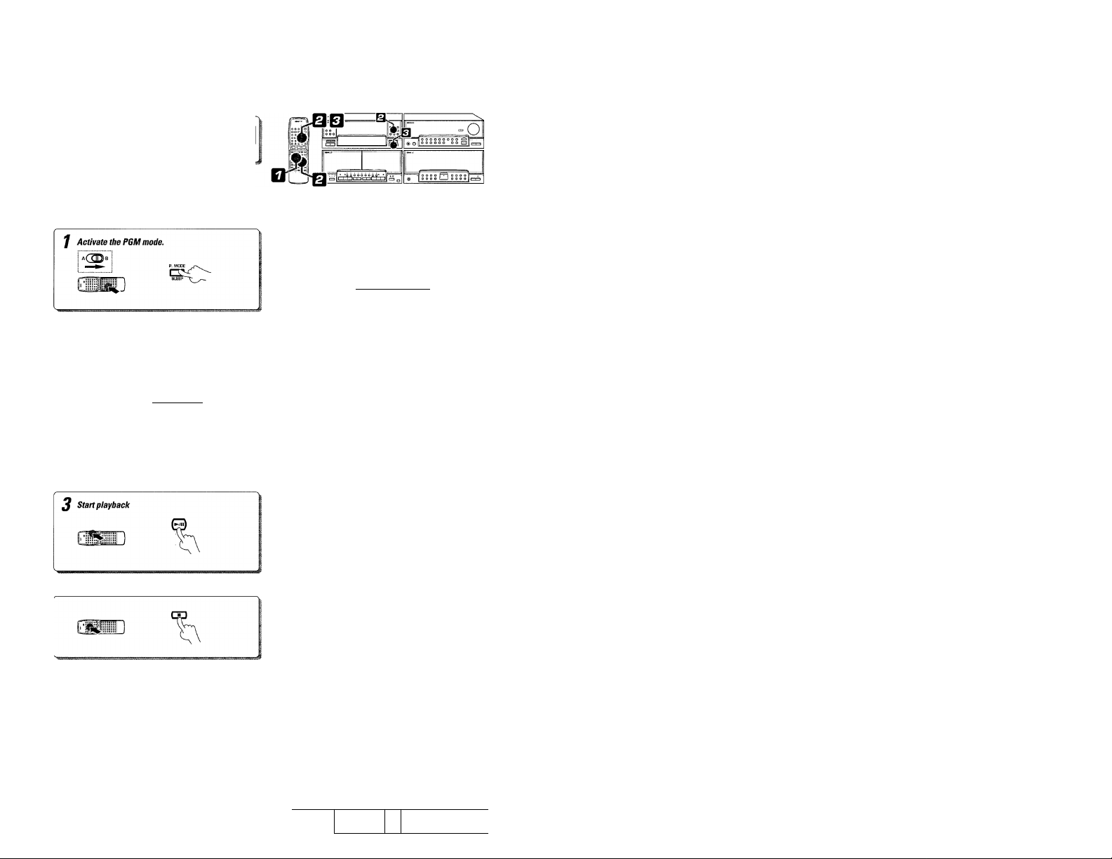
Programming tracks in desired order
Only "SINGLE TIME" is
displayed in program mode.
U ri I n ■ n n ■'
I U I u ■ U U t
Enter track Nos. in the order you want to play them.
To select tracks from more than one CD, repeat steps ©
and © above.
To stop playback To return to playback in order of track Nos.
(D Select the disc No.
[within 3 seconds!]
D
Select the track No.
Displays the entered track No.
• Up to 32 tracks can be programmed. FULL is displayed if you at
tempt to program a 33rd track.
• If you make a mistake, press the CLEAR key and enter the track No.
from the beginning.
• If the track No. is not selected within 8 seconds after having se
lected the disc No. all of the tracks on the disc will be programmed.
• If a disc No. which is not present in the magazine is entered, it is
programmed temporarily but canceled at the time of playback.
• Tracks will be played in the order they were programmed {in order of
P Nos.).
• When the or key is pressed during playback, the track will
be skipped in the direction of the pressed button.
» Playback in the original order of tracks starts with the track being
played.
Use the following procedure to play CDs in the original order
of tracks from track No. 1.
■
wf]
i»i
' - »J
m\
1
Page 27

To check the programmed tracks \ Remote control unit oniT]
To add a track to the program \ Remote control unit only [
To change a track in the program \ Remote control unit
CD V
Auto space function
This function is convenient for recording CD on a cassette tape. When
the SPACE key is pressed during programming of tracks, a non-re- j
corded space of a fe\w seconds will be created between tracks. By ,
recording tracks with these spaces on tape, the search and repeat
play operations of tape using the DPSS function (which works by
searching the non-recorded spaces) can be performed reliably.
• Even when the performances of two tracks are continuous (which
occurs with classical or live recording music), the spaces will be
created if they have different track Nos.
• To cancel the creation of space, press the SPACE key again.
bos P- P S
I Each time the key is pressed, the program No. (P-NO) and the disc
No. are displayed.
I The previous display resumes in a few seconds.
• When a track No. is entered, the track will be added to the end of
the existing program.
To clear tracks from the program
Press to clear tracks from the end.
Remote control unit
'll
/7 5
P- OS
t Press the CHECK key repeatedly until the track No, to be changed
is displayed.
• Press while the P.C. indicator is lit.
• The track being played cannot be changed.
I
Remote control unit only |
• Each time the key is pressed, the last track in the program is cleared.
• The track being played cannot be cleared.
» The entire program is also cleared when the P.OPEN/CLOSE key
is pressed.
Page 28

Preparation
I Select the "CD" input with the MAIN
INPUT key.
► Load discs in the CD player.
Repeated playback
To repeat only the programmed tracks
Time display on CD player
Each press of the TIME key changes the displayed contents.
(T) Elapsed time of track being played
(|) - Remaining time of track being played
(3) Elapsed time of entire disc
—'®
IS
Remaining time on entire disc
(- - - - The "SINGLE TIME" display remains in this condition
during playback of track No. 21 or later.)
» Only the SINGLE TIME displays are shown in the PGM and RAN
DOM modes.
Press so that the "PGM" Indicator lights.
» If the track No, is not selected within 8 seconds after having se
lected the disc No. all of the tracks on the disc will be programmed.
» All of the programmed tracks will be repeated.
» In case only one track is programmed, only that track will be re
peated.
» Up to 32 tracks can be programmed by repeating steps (D and ®.
» To play only the disc on the Plus-1 tray repeatedly, press the Plus-1
tray in step (D and wait for more than 8 seconds.
UD-959 [En)
To repeat all discs
Press so that the "REPEAT" indicator lights.
1— n 1 ri ■ n n
Is
►
U 1 u ■ u u
3 4 5
To stop repeated playback
Press the REPEAT key again.
• The REPEAT indicator goes off and the playback following the cur
rent mode of the CD player starts.
• All of the tracks on the all of the discs in the magazine and Plus-1
tray will be played repeatedly.
Press so that the "PGM" indicator goes off.
b 3.-Re
Press s0 that the "REPEAT" indicator lights.
Is ►
Press the REPEAT key again.
• The REPEAT indicator goes off and the playback following the cur
rent mode of the CD player starts.
b a 1
Page 29

Preparation
- ^ ^ [p;^ II^PLIT key.
^ • Load discs in the CD player.
• Select the "CD" input with the MAIN
Playback in a randontortler (Random playback)
Press so that the "PGM" indicator goes off.
01, ,
' n I n ■ n n '
/ LI t U ■
a.
2 Select discs.
To select one disc
1
--------
DISC
-------
cn-nn-nn
ADJUST EXE.
ENTER CLEA^ WECT
To select all discs
1
1
RANDOM
AITIM6Rr~v^^^^r--
Select
RANDOM ONE.
To select another track in the middle of playing one
• Pressing the w-« key once returns to the beginning of the track
being played.
Select
RANDOM ALL.
Each press of the RANDOM key changes the random playback
modes.
(D RANDOM ONE : Random playback from a single disc.
©RANDOM ALL : Random playback from all discs.
@OFF ; Random playback is OFF.
Example when track No. 7 of disc No. 3 is selected first
-/ n ~i n ■ n n
►
—lui u ■ u u
L n n n ■ n n
-1 LI J U ■ U U
• Random playback by selecting tracks at random after every track.
Example when track No, 3 of disc No. 5 is selected next
"RANDOM ONE" or "RANDOM ALL" indication
► It will never happen that the same track is repeated consecutively
twice, but it may happen that a same track is played twice or more.
To cancel random playback
Press so that the
"RANDOM" indicator
goes off.
• Press the ■ key to stop playback.
• Press the RANDOM key to start normal playback.
&
Page 30

J)^CASSETTE
Playback of tape
Tppe playback
/ Select the “TAPE" input
CIS
2 Load a cassette tape. ’ ^1
To stop playback
t Do not press the eject key until the tape has stopped completely.
© open the door.
® Insert a tape and close the door.
Each press changes the inputs as follows.
® TUNER (frequency display) disolaved*^^^
- -ЯРЕ
Ф MH/URT
® I'lHED
-----
® ПУ nUX
• The type of tape, that is, Nornnal, Chrome or Metal, is set automati
cally.
• Remove tape slack before loading.
• Close the door securely.
Each press switches the modes as follows.
© "c^"....Endless playback occurs.
@ ....Playback stops after having played a side.
I— © "7=2" ....Playback stops after having played the two sides.
!-► © DOLBY NR "B"........................General NR.
I
— ©DOLBY NR "OFF"
• Select the Dolby NR mode according to the recording condition of
• When the remote control unit is used, set the A/B switch according
(If the ■< key is pressed, only tape side B will be played
and tape will stop after it.)
® DOLBY NR "C"
the tape.
to the deck to be operated.
(no indication)
......................
..................
.....Dolby NR is not used.
r H PE
NR with higher performance.
To operate deck A
To operate deck В
To wind tape at high speed
icia
To fast wind in direction VK:
I Press the ■ key to stop fast winding.
Preparation
I Select the "CD" input with the MAIN
INPUT key.
» Load discs in the CD player.
Time display on CD player
Each press of the TIME key changes the displayed contents.
■? .Í
Elapsed time of track being played
^ 7 Remaining time of track being played
45 Elapsed time of entire disc
UD-959 (En]
Page 31

Use the following procedure to play tapes in decks A and B
alternately.
Relay playback
f Load tapes.
2 Seiect the playback modes.
3 Start playback.
Dolby Noise Reduction (NR}
The Dolby NR system is used to minimize the hiss noise heard when
playing tape. The system has the B type and C type, and the same
type should be used in recording and playback to obtain the noise
reduction effect.
When you record a tape, it is recommended to write the type used,
"B" or "C", on the cassette label
Dolby B NR: Generally-used Dolby NR.
Dolby C NR: Features a higher noise reduction effect than
The use of Dolby C NR is recommended if you record tapes to be
played on this unit.
©Select the "TAPE" input with the
MAIN INPUT key.
^ (D Insert tapes.
the B type.
• The tape sides indicated by the tape transport direction indicators
will be played.
Each press switches the modes as follows.
® "ctci".... Relay playback does not occur with this position.
@ ....Playback stops after having played one side on each
of tapes in decks A and B.
(3) ....The two sides of tapes in decks A and B will be played
r
(-► ©DOLBY NR "B"
I— ©DOLBY NR "OFF"
• Select the Dolby NR mode according to the recording condition of
• Relay playback starts with the deck corresponding to the pressed
Transport direction indicators
The and ► indicators indicate the current direction in which the tape
advances when playback or recording is started automatically by the
easy operation function, etc. This direction is the direction stored in
memory when the tape was last stopped.
(To change the direction, press the ► key for the opposite direction
then press the ■ key.)
repeatedly
............
® DOLBY NR "C".......................NR with higher performance.
(no indication)
the tape.
key.
.............General NR.
.......................
Dolby NR is not used.
Transport direction indicators
Page 32

DPSS (Direct Program Search System)
I The DPSS is capable of detecting non-recorded spaces of
more than 4secondsas "blanks between programs". It can be
used in four ways as described below.
Non-recorded spaces (Blank)
1. Skip search
Plays the desired music program from the beginning by skipping programs until there.
Up to 16 programs can be skipped.
2. Dash & play
3. Rewind playback
4. One-program repeat playback
Rewinds tape to the beginning and restarts playback from there.
Plays a single music program repeatedly up to 16 times.
Skip search
During playback of side A (while > is lit)
To play the next program : Press once.
To play the 4th program
after the current program : Press 4 times.
n
To return to the beginning
of the current program : Press once.
To play the 4th program
before the current program : Press 5 times.
1. The DPSS cannot be used on decks A and B simultaneously.
I Notes I
2. The DPSS may not function normally with the following kinds of tape.
• Tapes containing several no-sound intervals of more than 4 seconds, such as conversation and talk tapes.
• Tapes containing pianissimo sections, such as classical music tape.
• Tapes in which large noise is recorded in blanks between programs.
• Tapes containing blanks between programs that are shorter than 4 seconds.
• Tapes recorded at low level.
• Tapes recorded by cross-fade recording (in which the beginning of next program is overlapped on the end of previous program).
During playback of side B (while M is lit)
To return to the beginning
of the current program : Press once.
To play the 4th program
before the current program : Press 5 times.
To play the next program ; Press once.
To play the 4th program
after the current program : Press 4 times.
o
Page 33

Dash & play
/ Select the playback modes.
2 Start dash & play.
) Select the
MAIN INPUT key.
r~rV^
When a non-recorded space of more than 10 seconds is detected dur
ing playback, that space is automatically skipped by fast winding to
play only the tape sections where sound is recorded.
Each press of the key switches the modes as follows.
® "cto" ....The two tape sides are played 8 times, after which
playback stops.
(D "rrt" ....A tape side is played 8 times, after which playback
— (D “7=3" ....The two tape sides are played once, after which play
• If "=>" is selected while tapes are present in both decks A and B,
I Main unit only I
stops,
back stops.
Dash & Play of the second deck starts after Dash & Play of the first
selected deck has completed. This is repeated 16 times, after which
the playback stops.
Press simultaneously.
One-program repeat playback
During playback of side
B (while is lit)
Press during playback,
(when side A is facing toward you)
Rewind playback
During playback of side A (while ► is lit]
Press simultaneously,
(when side A is facing toward you)
i When the ■ key is pressed, playback stops and the dash & play is
canceled.
• The program being played will be repeated 16 times, after which
normal playback resumes.
• When the ■ key is pressed, playback stops and the one-program
repeat is canceled.
I Main unit only I
► Tape is rewound until the beginning of the program being played,
then its playback starts.
Page 34

Broadcast Reception
? Use the following procedure to receive radio stations.
It is also possible to receive them by one-touch operations by
storing up to 20 stations in the preset memory.
I
Receiving broadcast stations
f Select the “TUHBR" input.
Q
2 Select the frequency band.
DISPLAYkey
Every time the DISPLAY key is pressed, the display contents of the
preamplifier/tuner unit changes.
Each press changes the inputs as follows.
® CH
(g) TUNER (frequency display)
(D JRPE
® MJI/HRJ —
® I'lHED
^ ® Ri' RUX
Each press alternates the band.
rKA AM/FM (MW/LW/FM)indicators
® FM
(DMW
r
(DLW
Each press alternates the mode.
г-►- ©AUTO lit (Auto tuning)
I— (D AUTO not lit (Manual tuning)
• Normally, use the AUTO (Auto tuning) mode.
Use the manual tuning mode in case the reception is noisy due to
i^weak waves. (In the manual mode, stereo broadcasts are received in
monaural.)
Auto tuning : Each press receives the next station.
Manual tuning : Press the key repeatedly or hold it depressed until a
Each press changes the display as follows.
■►©Inputsource display : The selected input source is dis
— ® Month/date display J ing is done, these change to the fre
While the power is OFF, pressing the DISPLAY key alternates be
tween the month/date and clock displays.
station is received.
(2) Presence mode display
(D Clock display "I When an operation related to turn-
A radio frequency should
be displayed.
5/7'
5 Z 5 /7 "
Lights during
stereo reception.
Frequency display
5^5/7“
played, When the TUNER input is
selected, the frequency being re
ceived is displayed.
quency display for a few seconds.
Page 35

Receiving radio station by specifying its frequency
f Select the "TUNER" input.
2 Select the frequency hand.
J specify the frequency.
А(ПП I
©
FlilliilFI
I Remote control unit only |
- -
DIRECT
©&L.4^
Each press changes the inputs as follows.
© CH
® TUNER (frequency display)
© TRPE
@ MH/IinJ
© i'lUED
— ® Rl' RU'/\ Press so that a frequency is displayed.
Each press alternates the band.
[-►(j
r-*-©FM
®MW
I— ®LW
Desired station
FM 90 MHz
FM 102.5 MHz (Т],Ш],[1],[1]
AM (MW) 810 MHz
AM (MW) 1260 kHz
"TUNED" indicator iights
when a station is received. Frequency dispiay
Frequency band indicator
Order of pressing numeric keys
[9],[o],®,0
®.ш
ш,®,®
В г
(100 kHz space)
(50 kHz space)
(100 kHz space)
(50 kHz space)
(10 kHz space)
(9 kHz space)
(10 kHz space)
(9 kHz space)
В В БО^
» If you enter a wrong frequency, the display will blink. In this case,
you should enter the correct frequency.
I If you make a mistake, press the CLEAR key and restart the fre
quency entry from the beginning.
Page 36

I^TUNER
, Up to 20 broadcast stations can be stored as preset stations
with a preset number assigned to each of them.
S
Once stations are preset, they can be received by simply
i specifying their numbers.
Storing radio stations in memory (Station preset)
preparation.
I Receive a station to be stored in pre
set memory.
ml_______________Imit®
ssll
f' °o
r,
/ Press the ENTER key during reception.
Go to step 2 within 5 sec.
If more than 5 seconds have elapsed,
press the ENTER key again.
® Select the "TUNER" input with the
MAIN INPUT key.
I Remote control unit only |
• The station being received will be stored in preset memory.
Press the numeric keys as follows.
To store the station in preset "15" ; |+1D|,
To store the station in preset "20" ■■ ra.ra.ioi
• To preset other radio stations, repeat steps 1 and 2 for each of
them.
• If the preset number assigned to a station has already been as
signed to another, the new memory content replaces the old con
tent.
I
Remote control unit only |
Press the numeric keys as follows.
To received the station in preset "15": |+10|, fsl
To receive the station in preset "20" ; |+10|, l+10|, 0
Receiving preset stations in sequence (Preset call)
Press the P.CALL key.
® Select the "TUNER" input with the
MAiN INPUT key.
(é) (è)
I Remote control unit only |
• Every time the key is pressed, the preset stations are switched over
as follows.
When A is pressed j ^ B
When V is pressed
When a key is held depressed .....Preset stations will be skipped at
I--------------------------------------------------1
........................................
' — — B
.....
an interval of about 0.5 second.
!B~^ IB > BB
IB — IB—BB
1
Page 37

Page 38

3D-environmental sound system
This system allows you to reproduce two input sources, for
example the CD and TAPE, separately from the main speakers
3S
and OMNI speakers. Overlapping the environmental sound
from the OMNI speakers on the music from the main speakers
will bring an atmosphere as if the listener is listening to the
music in the middle of that environment.
To enjoy the environmental sound play, it is required to
install the OMNI speakers (OMNI-A5: optional).
Enjoying music with sound of presence
The noise and atmosphere of a concert hall, jazz club or sta
dium will enhance the ambience of music.
Play the desired track from the provided CD through the
OMNI speakers and play music through the main speakers.
When the presence sound is combined with one of
^ the DSP presence modes, the atmosphere can be
made more realistic.
Note on provided CD
When it is required to play a music CD while reproducing one of the
environmental sounds on the CD provided, record the desired envi
ronmental sound track of the CD ON to a tape, play this tape through
the OMNI speakers and play the desired music of the music CD
through the main-speakers. By using the repeat playback function of
the CD player unit when recording onto tape, the same track can be
recorded repeatedly on it.
Repeat playback Recording [p^
O —
h/
^UiT^ A 0 ^
° O
O ^
1 o
IMI
1 1
3D stands for "three-dimensional".
The provided CD has been produced to reproduce the height and
directional properties as well as the left/right positions and feeling
of depth of the sound sources. We strongly recommend that you
also experience the world of 3D environmental sound!
Storing radio stations in memory (Station preset)
Up to 20 broadcast stations can be stored as preset stations
with a preset number assigned to each of them.
Once stations are preset, they can be received by simply
specifying their numbers.
preparation.
• Receive a station to be stored in pre
set memory.
"V ■ “S
Page 39

Recording (Deck B only)
Preparations
I Load a cassette tape in the deck.
I Select the tape transport direction {m
or ►).
» Select (two-side recording) or
"zd:" (one-side recordina).
^^
Page 40

Recording (Deck B only)
This unit incorporates the CRLS (Computer Recording Level
System) automatic recording level setting and Dolby HX Pro
headroom extension to allow excellent sound recording with
simple operation.
The equalizer and presence effects applied to the music are
recorded together with the music sound.
When the Environmental Sound function is applied, the envi
ronmental sound can be recorded mixed with the music sound.
Enjoy the Environmental Sound recording by combining the
CD and tuner sounds or an external component connected to
the system. (In this case, it is not possible to record the sound
of deck A onto deck B.)
Preparation for recording
ir _ .......-pi
• The type of tape, that is. Normal, Chrome or Metal, is set automati
cally,
» Remove tape slack before loading.
t When the microphone is not used, set the MIC MIXING control
fully counterclockwise to the minimum position.
• When recording is started, the tape is transported in the direction
selected in this step.
• Wind the tape to the position where recording is to be started.
Each press of the key switches the modes as follows.
® "cio" ....(In this case, too, the two tape sides are recorded,
after which recording stops.)
(D "zT;" ....A tape side is recorded, after which recording stops.
r
@ „..The two tape sides are recorded, after which record
ing stops.
Each press of the key switches the modes as follows.
г► 0 DOLBY NR "B"..........................B type (general type).
(D DOLBY NR "C"......................C type (with higher performance).
I— ©DOLBY NR "OFF"
(no indication)
.......................
Dolby NR is not used.
Page 41

Recording (Deck B only)
Preparations
If the DUAL SOUND key is ON and the "TAPE" is selected
as the SUB (OMNI) INPUT, recording is not possible.
Start auto recording level adjustment.
m Load a cassette tape in the deck.
• Select the tape transport direction (-^
or^).
• Select (two-side recording) or
":zd;" (one- side recording).
• Select the Dolby NR mode.
• (Insert a disc in the CD player.)
(D Play the contents to be recorded
(or receive the radio station to be
recorded).
® Blinks. Lights.
The equalizer and presence effects applied to the music are recorded
^together with the music sound.
Each press changes the inputs as follows.
■© LH
® TUNER (frequency display)
(D TflPE
® nH/SRJ
® i'lHEn
® ni' RUi(
• When the CD is input is selected and if a disc has been set in the CD
player, its playback starts immediately.
• The bias adjustment consists of checking the characteristics of the
loaded tape and adjusting the deck to allow best-balanced record
ing. The adjustment data are held in memory unless the power is
turned OFF or the door of deck B is opened, so it is not required to
re-adjust the bias in case of re- recording.
• The bias adjustment completes in approx. 45 seconds, after which
the deck enters the stop mode.
• To abort bias adjustment in the middle, press the ■ key.
• Even if the bias adjustment is not performed, there will be no trouble
in recording because a general bias has been set depending on the
Normal, Chrome or Metal type of tape.
• The recording level setting completes in approx. 20 seconds, after
which the deck enters the record-pause mode.
• If recording is started during the setting (while the CRLS indicator is
blinking), distorted sound may be recorded.
• If the CRLS key is pressed during the setting (while the indicator is
blinking), the setting is interrupted and the deck enters the recordpause mode.
• If a non-recorded space of more than 5 seconds is detected after
the CRLS key is pressed, the recording level setting is aborted.
When recording a CD, if the track(s) to be recorded is se
lected by pressing a disc selector key or numeric keys
without pressing the ■ key, the recording of the cassette
deck starts automaticallay. (Synchro recording)
The source component to be
recorded should be displayed.
• Recording starts.
• Recording stops automatically when the tape side(s) to be recorded
have been recorded.
• If the LINEAR ACOUSTIC CONTROL setting is changed during re
cording with the DUAL SOUND ON, the recorded volume (or the
balance between the main and SUB-OMNI inputs) varies.
Page 42

Function of CRLS key
The CRLS sets the recording level automatically in 20 seconds by ana
lyzing the sound to be recorded.
If the key has never been pressed
....
The sound is recorded with the basic level set with the unit.
If the key is pressed
....
The recording level is set automatically and stored in memory
as the recording level to be used with the current input being
selected (CD, TUNER, AUX, etc.). From the next time on, this
recording level is set automatically for that input even if the
key is not pressed.
To return to the level used in previous recording
....
Press the ■ key while the CRLS indicator is blinking.
To return to the basic level
....
Flold the key depressed until the indicator goes off (for approx.
3 seconds).
UO-95g [En]
Re-recording
) Stop recording and rewind tape.
During recording
of side A (►)
(2) Press the • key twice.
(D Press the • key once.
To pause recording temporarily
To end recording in the middle
During recording
of side B (◄)
(when side A is facing toward you)
Blinks.
I If there is a non-recorded space of more than 4 seconds before the
recording start position, recording is aborted and tape is rewound
as shown below.
Tape stops after 2 sec.
of transport.
----------------------
Blank of 4 sec.
or more
*i Tune to be
Re-recording
Recorded tune !r| re-recorded
• If there is no recorded tune before, the tape will be rewound then
stopped.
► Tape stops after leaving a non-recorded space of approx. 4 sec
onds.
» When re-recording from the beginning of tape, feed the leader tape
(the first portion of tape that cannot be recorded) before starting re
recording.
I Recording will start.
• Press the • key to restart recording.
Dolby HX Pro
The Dolby HX Pro headroom extension system records high frequen
cies such as the cymbal sound clearly by controlling the bias current
during recording according to the frequency composition of the sound
being recorded. This system is activated automatically during record
ing with this unit.
Page 43

Copying tape (Tape dubbing)
Preparations
• Load a cassette tape in the deck.
• Select the tape transport direction
or^).
• Select “t=>" (two-side recording) or
"xzt" (one- side recording).
Recording tape
The contents of the tape in deck A can be copied onto the tape
in deck B.
UD-95a (En)
/ Start auto-bh
Approx,
45 sec. AUTOBiAs
• The bias adjustment consists of checking the characteristics of the
loaded tape and adjusting the deck to allow best-balanced record
ing. The adjustment data are held in memory unless the power is
turned OFF or the door of deck B is opened.
• The bias adjustment completes in approx. 45 seconds, after which
the deck enters the stop mode.
• To abort bias adjustment in the middle, press the ■ key.
• Even if the bias adjustment is not performed, there will be no trouble
in recording because a general bias has been set depending on the
Normal, Chrome or Metal type of tape.
The deck A operation keys are inactive during dubbing. During
high-speed dubbing, the cassette decks cannot be operated from
the remote control unit.
• Dubbing starts.
• Dubbing ends automatically when the side{s) to be dubbed has been
completed-
To stop dubbing
Press the ■ key of deck B
► Both decks A and B stops.
To pause dubbing
For high-speed
dubbing
I Notes I "I - The recording level adjustment is not necessary in dubbing.
2. The DOLBY NR key is not active in dubbing mode. The tape recorded on deck B is given the same Dolby NR condition as the tape
played on deck A.
3. To prevent interference of noise, the unit should be separated at a distance from a TV during high-speed dubbing.
4. To avoid sound quality degradation, use the normal-speed dubbing when dubbing from a tape recorded \Vith a high recording level.
For normal-speed
dubbing
► Only deck B enters the record-pause mode after leaving a non-re-
corded space of approx. 4 seconds in case of normal-speed dubbing
or approx. 6 seconds in case of high-speed dubbing.
» To restart dubbing, press the DUBB NORM or DUBB HIGH key
which was pressed to pause dubbing.
•
Page 44

CD edit recording
The following procedures allow edit recording of CDs by
simply setting the length (recording time) of the tape. All of
other operations will be assumed by the UD system, from the
recording level and bias settings to the complicated process
ing at the end of two sides of tape. (OCRS)
Desired CD tracks of more than one CD can be edited in the
desired order. In this case, use the "program edit recording"
procedure.
Select the type of edit recording.
Do you care about the order of tracks?
f Timed edit recording
Program edit recording
Cross-faded
(two tunes overlapped)
How should the interval between tunes be?
Is the tape recording
time enough for the CD?
Al edit recording
Space (same as
recording on CD)
Cross-fade edit recording
f Fade edit recording
CCRS (Computer Controlled Recording System)
The CCRS allows to record CD on tape with a one-touch operation.
When the CCRS key is pressed, the contents of CD and the characteristics of the tape used are checked in approx. 90 seconds, the recording level
and bias are automatically set accordingly and recording starts. After the recording, it is also stopped automatically. Pressing the CCRS key ON
switches the DUAL SOUND function automatically OFF.
The auto bias setting is cleared when the power is turned OFF or the door of deck B is opened. (The "AUTO BIAS" indicator is lit while the auto bias
data is held in memory.)
The edited data is cleared when the power is turned OFF or when the CD is stopped.
Jl-F-P-
Function of CRLS key
The CRLS sets the recording level automatically in 20 seconds by ana
lyzing the sound to be recorded.
If the key has never been pressed
....
The sound is recorded with the basic level set with the unit.
If the key is pressed
....
The recording level is set automatically and stored in memory
as the recording level to be used with the current input being
selected (CD, TUNER, AUX, etc.). From the next time on, this
UD-95S [En)
Page 45

Fade-in/fade-out
Fade-out : Ending a tune by gradually decreasing the volume.
^ Fade-in : Starting a tune by gradually Increasing the volume.
Cross-fade : Combination of fade-out and fade-in so that the sounds
of two tunes are overlapped.
if
^ Program edit recording
I From one CD |
CD tracks are recorded in the order they
are programmed. The tune interrupted at
the end of tape side A is erased and side
B starts from the beginning of that tune.
The tune interrupted in the middle at
the end of tape side B is erased.
From more than one CD
CD tracks of several CDs are recorded In
the order they are programmed. The tune
interrupted in the middle at the end of
tape side A is erased and side B starts
from the beginning of that tune.
Cross-fade edit recording
Tunes are connected by fade-out and
fade-in, and the tune interrupted at the
end of tape side A is re-recorded at the
beginning o tape side B.
^ Timed edit recording
The order of CD tracks are changed au
tomatically so that no tune is interrupted
at the end of tape sides A and B.
M
Al edit recording ^ ^
In case the recording time of tape is
shorter than the playing time of CD, all
of CD tracks (up to 20) are accommo
dated by fading out the ending parts.
^ Fade edit recording
CD tracks are recorded in the order they
are recorded. The tune interrupted at the
end of tape side A is faded out and side
B starts with fading in from the middle
of that tune.
The CD tracks can be recorded in the same order as they are
recorded on the CD or as they are programmed.
The tune interrupted in the middle at the
end of tape side B is simply faded out.
Page 46

slJ’J’"
Program edit recording
Use the following procedure to record CD tracks in the order
, programmed by yourself so that no tune is interrupted in
the middle at the ends of tape sides.
m Load a cassette tape in deck B.
« Select the tape transport direction
or^).
• Select "Z)" (two-side recording).
» Select the Dolby NR mode.
I Select the "CD" input with the MAIN
INPUT key.
• Insert disc(s) in the CD player.
Enter disc Nos. and track Nos. in the order you want to record them. (Editing)
© Enter the disc No.
n I PROGRAM ADJUST EXE.
ENTER
[Wthin 8 second
I
To edit tracks from more than one CD, repeat © and
® for each CD.
To check the edited contents
To dear the edited contents
I [NjQtes I CCRS key is pressed during playback of CD, the playback stops and the CCRS setting (preparation for edited recording)
starts.
2. The automatic recording level setting operation in the edit recording utilizes a section suitable for this purpose in the CD present in the
CD player.
3. Edit recording is not possible with CDs containing a track that is longer than one tape side, which may occur with classical music, etc.
4. If the deck is set for one-side recording {z^), the processing at the tape end is applied only on side A.
) Enter the track No.
—
ilooj
ai
------
L
CTfiiiiHiiiiTH
^ The equalizer and presence effects applied to the music are recorded
^together with the music sound. -»[p^ -»[p^
(In case of high-speed CCRS recording, the equalizer effect should be
switched off.)
Press the numeric keys as shown below....
To enter track Nos. 2, 5 and 25;
F^.isl.ra.m.rsl
• Select CD tracks so that their total playing time does not exceed the
recording time of the tape.
• Up to 32 tracks can be programmed. FULL is displayed if you at
tempt to program a 33rd track.
• If you make a mistake, press the CLEAR key and enter the track No.
from the beginning.
• The CCRS setting will not occur if the track No. is not selected within
8 seconds after having selected the disc No.
• The SPACE key and REPEAT key are invalid.
• The recording level and bias will be adjusted automatically in approx.
90 seconds, after which recording starts.
• In editing from more than one CD, the CCRS setting operation is
performed after every disc change. In this case, the deck stops au
tomatically and restart recording after having completed the CCRS
operation.
• The Dolby NR is switched OFF during high-speed CCRS recording.
Therefore, the Dolby NR should be switched off when playing the
tape recorded by high-speed CCRS recording.
• The frequencies of musical notes are doubled during high-speed
CCRS recording. Therefore, the recorded contents cannot be en
joyed as music even when the sound is monitored through the
speakers.
Page 47

Cross-fade edit recording
The cross-fade editing may be easier to understand by saying
that it is a function for cross-fading tunes than saying that it
edits the order of tunes. This function can be used in combi
nation with the program edit recording and timed edit record
ing as well as in simple recording of CD tracks in the order
they are recorded on the CD.
Preparations
.
In case the order of tracks on CD is to be edited
In case the CD tracks are to be recorded in the order they are recorded on CDs
• Load a cassette tape in deck B.
• Select the tape transport direction {◄
or^).
• Select "ZD" (two-side recording).
• Sele ct the Dolby NR mode.
• Select the "CD" input with the MAIN
INPUT key.
• Insert disc(s) in the CD player.
® Perform the editing steps of pro
gram or timed edit recording.
D Start edit recording.
® Select the disc to be recorded.
6 © ©
E
© 6 6
6
D Start edit recording.
The equalizer and presence effects applied to the music are recorded
^together with the music sound.
• After the editing operation, do not press the OCRS key, but return to
this page and go to step If the OCRS key is pressed after edit
ing, the corresponding edit recording will start in place of cross-fade
recording.
Program editing ^ ^
Timed editing * gg
• High-speed recording is not possible.
• The recording level and bias will be adjusted automatically in approx.
90 seconds, after which recording starts.
• High-speed recording is not possible.
• The recording level and bias will be adjusted automatically ir
90 seconds, after which recording starts.
If a CD track which has already been faded in or out is recorded by cross-fade recording, the space between the adjacent tune may
become very long.
Page 48

Timed edit recording
By specifying the recording time of the tape used, CD tracks
( can be recorded with their order automatically changed so
!. that no tune is interrupted at the end of tape sides A and B.
I
Preparations
• Load a cassette tape in deck B.
• Select the tape transport direction H
or^).
• Select
"ZD"
• Select the Dolby NR mode.
• Select the "CD" input with the MAIN
• Insert disc(s) in the CD player.
(two-side recording).
INPUT key.
f, The equalizer and presence effects applied to the music are recorded
together with the music sound.
(In case of high-speed CCRS recording, the equalizer effect should be
switched off.)
Should be OFF.
Each press switches the edit modes as follows.
® EDIT
I
— d) A \ EDIT
• To use the auto space function, press the SPACE key .To cancel the auto
space function, press the P.MÜDE key and restart from step 2.
Press the numeric keys as shown below....
46-, 54-, 60- or 90-minute tapes can be selected simply by pressing
^ the TIME key for the required number of times.
After entry, press the EDIT MODE key then proceed to step 4.
• Up to 20 tracks can be edited.
• CD tracks will be edited automatically onto tape sides A and B. After
editing, the EDIT indicator stops blinking and starts to light steadily.
Press so that the "EDIT" indicator lights.
Lights.
30-minute tape; |+10|,|+10l,k10|,ro1
46-minute tape; , S. [±51] - ®. [U
• The recording level and bias will be adjusted automatically in approx.
90 seconds, after which recording starts.
• The tape and CD stop automatically when recording has completed.
• The Dolby NR is switched OFF during high-speed CCRS recording.
Therefore, the Dolby NR should be switched off when playing the
tape recorded by high-speed CCRS recording.
• The frequencies of musical notes are doubled during high-speed
CCRS recording. Therefore, the recorded contents cannot be en
joyed as music even when the sound is monitored through the
speakers.
Page 49

Al edit recording
In case the recording time of tape is shorter than the playing
time of the CD to be recorded, all of CD tracks (up to 20) can
be accommodated by fading out the ending parts.
Preparations • Load a cassette tape in deck B.
• Select the tape transport direction (◄
or ►).
• Select "ID" (two-side recording).
• Select the Dolby NR mode.
• Select the CD input with the MAIN IN
PUT key.
• Insert disc(s) in the CD player.
The equalizer and presence effects applied to the music are recorded
together with the music sound. “ES
(In case of high-speed CCRS recording, the equalizer effect should be
switched off.)
Should be OFF.
IS
ir
pS
Each press switches the edit modes as follows.
!-► ® EDIT
I
— @ Al EDIT
I The SPACE key and REPEAT key are invalid.
Press the numeric keys as shown below....
30-minute tape: [Tio]. [Tio], [7io], (^
46-minute tape: |+10|,|+1o1.k10|,rfTo],rBl
^46-, 54-, 60- or 90-minute tapes can be selected simply by pressing
the TIME key for the required number of times.
After entry, press the EDIT MODE key then proceed to step 4.
• CD tracks will be edited automatically onto tape sides A and B. After
editing, the Al EDIT indicator stops blinking and starts to light
steadily.
• The recording level and bias will be adjusted automatically in approx.
90 seconds, after which recording starts.
• If the specified tape recording length is long enough, all CD tracks
will be recorded without being faded out.
• The tape and CD stop automatically when recording has completed,
• The Dolby NR is switched OFF during high-speed CCRS recording.
Therefore, the Dolby NR should be switched off when playing the
tape recorded by high-speed CCRS recording.
• The frequencies of musical notes are doubled during high-speed
CCRS recording. Therefore, the recorded contents cannot be en
joyed as music even when the sound is monitored through the
speakers.
• The Al edit recording cannot be combined with cross- fade edit re
cording.
S'r
Press so that the "Al EDIT" indicator lights.
Lights.
•
SlNOLiTlME 1 2 3 4 5
p n 7'
/ u 1 U ■ U U 16 1
n . n n 1
7 8 S 10
2 13 14 15
7 18 19 20
Page 50

Fade edit recording
The tune interrupted at the end of tape side A is faded out and
side B starts with fading in from the middie of that tune. The
d.
t tune interrupted at the end of tape side B is simpiy faded out.
Preparations
• Load a cassette tape in deck B.
• Select the tape transport direction (◄
or^).
• Select "Z>" (two-side recording).
• Select the Dolby NR mode.
• Select the "CD" input with the MAIN
INPUT key.
• Insert disc(s) in the CD player.
^ The equalizer and presence effects applied to the music are recorded
i^together with the music sound. »
(In case of high-speed CCRS recording, the equalizer effect should be
switched off.)
Should be OFF.
iS
Selected disc No.
1 U 1
p n 7
U ■ U U
n-n n
12 3 4 5
'll 12 13 14 15
16 17 18 19 20
J Start edit recording.
1. When the CCRS key is pressed during playback of CD, the playback stops and the CCRS setting (preparing edited recording) starts.
I Notes I
2. The automatic recording level setting operation in the edit recording utilizes a section suitable for this purpose in the CD present in the CD player.
3. Edit recording is not possible with CDs containing a track that is longer than one tape side, which may occur with classical music, etc.
4. If the deck is set for one-side recording (zii), the processing at the tape end is applied only on side A.
5. When the last tune of tape side B is faded out, the ending part of the last but one tune may sometimes be faded out if the space between it and
the last tune is short.
^ By specifying the recording time of the tape used, CD tracks
can be recorded with their order automatically changed so
For normal-speed
recording.
• The recording level and bias will be adjusted automatically in approx.
90 seconds, after which recording starts.
• The CD tracks are recorded in the order they are recorded on the CD.
• The Dolby NR is switched OFF during high-speed CCRS recording.
Therefore, the Dolby NR should be switched off when playing the
tape recorded by high-speed CCRS recording.
• The frequencies of musical notes are doubled during high-speed
CCRS recording. Therefore, the recorded contents cannot be en
joyed as music even when the sound is monitored through the
speakers.
.(TOb I
Page 51

To check the edited contents \ Remote control unit oni^
To clear the edited contents
IBiign
10 ^ R - 0 I
• Each time the key is pressed, the edited CD track Nos. are displayed
in order.
• The edited data is cleared entirely.
Page 52

J) J'-i' RECORDING
s
Recording CD while listening to another source
Use the following procedure to listen to another input source
while recording CD onto tape.
I Load a cassette tape in the deck B.
• Select the tape transport direction (◄
or ►).
I Select (two-side recording) or
(one-side recording).
» Select the Dolby NR mode.
> Select the "CD" input with the MAIN
INPUT key.
» Insert a disc in the CD player.
iii
SI TIssssnssisEn
Lights.
L ]]
rr-=j^3
I
----------- li
■n N
To cancel CD REC.
» The CD REC cannot be cancelled while the REC indicator is lighting
or blinking.
» After the CD REC operation, be sure to press the CD REC key to
cancel it.
I Note I
In the CD REC operation, the equalizer and DSP presence effects cannot be recorded together with the CD sound.
The tune interrupted at the end of tape side A is faded out and
side B starts with fading in from the middle of that tune. The
Af nniB
Page 53

Page 54

Switching the displayed contents
Each press changes the display contents as follows.
(D Graphic equalizer display
IHHZ
Graphic equalizer display;
9 Shows how the frequency bands are compensated for.
Spectrum analyzer display:
Shows the levels of frequency bands that vary according to
the progress of sound.
Demonstration display:
The equalizer curves change one after another.
Display OFF:
Select this status when no display is required. The equalizer is
still active when when the display is OFF.
Character displays
The changes in the levels of the frequency bands can be
displayed in various patterns.
I
Press during the spectrum analyzer display.
® Select the spectrum analyzer dis
play.
ra^AПACTEH
D Spectrum analyzer display Peak hold display
li ll i li 11II
it
II11 if li ii II li ii»
)
Demonstration display
------
© Display OFF
Each press switches the display patterns as follows.
® Normal
.. - »..:
i 1 i ii H ii H ii» y
liillillill»-
1 :l :l a "
:
:: "I”"“
||flyilyyyni
(D Shower
il»l!lii!flff|f!i|ii!!^[|fi||||ii»
(D Horizontal
@ See-through
a
u
j
---------- Peak hold display
IHHZ
¡1::
JJEMO
IHHZ
IHHZ
IHHZ
IHHZ
Page 55

Al AUTO
When the Al key is pressed before playing a CD, the recording in the
CD is analyzed in about 30 seconds and the optimum equalizer curve
and the LiNEAR ACOUSTIC CONTROL setting {volume balance be
tween the main and omni speakers) are set automatically. After this,
the CD starts to be played from the first track.
Al FOCUS
When playing a CD with a DSP presence mode, the Al FOCUS sets the
optimum ASFC (a setting element determining the sound field
expansion) value in addition to the setting made with the Al AUTO.
PlaYina CD with ootimumtone setting I Al A UTO)
Press one of the disc selector keys to select the
1
2 Press the Al key.
DC
0 Blinks.
Goes off
__
• Ensure that the F.4CH, F.2CH and DEPTH indicators are off.
iiiilllnloiiljlillljiilEsSSu
■ In approx. 30 seconds, playback starts fronn the first track.
To cancel
During Al setting : Press the Al key again. (The equalizer curve immedi
After Al setting ; Press the FLAT key. (The equalizer curve becomes
• The setting is also canceled when one of the LINEAR ACOUSTIC
CONTROL keys or the ■ key of the CD player is pressed.
Blinks. Lights.
Approx. 30 sec.
X
ately before will be recalled.)
flat.)
(I I J)
Playing CD with enhanced presence effect (Al FOCUS}
Press one of the disc selector keys to select the \ CD to be played.
Each press switches the sound fields as follows.
(T)RRENR
~ mu aujs
®5TR]IIUM
c
rr""
5RMPLI
> In approx. 30 seconds, playback starts from the first track.
Blinks. Lights.
Approx. 30 sec. jgj
cJ J
To cancel
During Al setting : Press the Al key again. (The equalizer curve imme
After Al setting : Press the FLAT key. (The equalizer curve becomes
• The setting is also canceled when one of the LINEAR ACOUSTIC
CONTROL keys or the ■ key of the CD player is pressed.
diately before will be recalled.)
flat.)
Page 56

Playing music with desired tone
15 kinds of preset equalizer curves can be recalled with
simple operation. These patterns can be selected according
®
to the tone and the category of music. Use them also accord-
- ing to your liking.
Preparations
CD
• Receive a radio station or play a CD o
-m TAPE
cassette tape.
TUNER
o
/ Switch the graphic equalizer effect ON.
Operations on the remote control unit
Each press of the M.CALL key changes the patterns and categories
as follows.
® MANUAL (Clear)
REFERENCE1 (Basic) -i—2-+3-h>4 — 5
REFERENCES (Scale) 1—2 — 3 — 4-+5
EQ, EFFECT
Each press changes the pattern names as follows.
® MANUAL (Clear)
I Clear tones based on proper com-
^ pensationsof the frequency bands. '
(D REFERENCE 1 (Basic)
Basic tones with proper enhance- "
ment of low and high frequency
bands,
1
----
(D REFERENCE 2 (Scale)
Crisp tone by enhancing
quency bands.
■ Select the category according to the genre or contents of the music
played.
> The following five categories are available for each of MANUAL,
REFERENCE 1 and REFERENCE 2,
1 -► Popular, fusion
2 -► Rock
3 -► Jazz
4 -► Classic
5 -► Movie
To cancel
Press the EQ.EFFECT key again.
■ . “ ■■ ..
• The equalizer curve on the display remains.
iHH Z
IK H Z
IK H Z
IHHf.
Page 57

Creating desired tone
Preparations
■* CD • Play the desired source.
■"ES the graphic equalizer effect on.
2 Select the frequency band to be adjusted.
3 Adjust the level of the frequency band.
• Press the EQ.EFFECT key to switch
TUNER • Press the DISPLAY key to display the
graphic equalizer display. -E9
mEouENcY^ frequency
T(
To increase
UENCY fri
To increase level
• Select the equalizer curve with the closest pattern to the curve to be
created.
• When the FLAT key is pressed, a curve can be created from a flat
condition.
Properties of frequency bands
Low
frequency bands
63-160 Hz
Medium
frequency bands
400 Hz~2.5kHz
High
frequency bands
6.3 kHz
Ultra-high
frequency bands
16 kHz
Musical instruments in the low bands
sound with stable feeling.
The vocal of singers seem to come to the
front or go to the deep depending on the
level adjustment.
When the level is increased, the sounds
of violin, flute, etc., become brighter.
The triangle, cymbal, etc. sounds brighter
and the sound become more delicate.
To decrease level
Storing the desired tone in memory
Preset the user-created equalizer curve.
Presence effects
Various modes for reproducing the effects of pres
ence are availabie. Select the mode according to the
piayed source or the component in your system.
DEPTH modes
-Ea 1
■ If there is another frequency band to be adjusted, repeat steps 2 and
3 for that band.
"MEMORY" lights.
!BHHZ
• Perform step ® while the MEMORY indicator is blinking.
• The user-created equalizer curve is preset under the pressed num
ber as one of the MANUAL patterns.
• If an equalizer curve has already been preset under the pressed key,
it will be replaced by the new equalizer curve.
To clear the equalizer curve created and stored by the user
Select the MANUAL patterns with the R/M key and hold the key
under which the curve to be cleared has been stored. It will be cleared
and the equalizer curve originally preset in the unit will be recalled.
Page 58

Recording tape for playback on car stereo or headphone stereo
f Play the source sound to be recorded.
2 Switch the graphic equalizer effect ON.
I
To cancel
Press the key so that both "CAR" and "HEADPHONE ST." go off.
„ •• ■■
Display when "HEADPHONE ST." is selected
Each press changes the patterns as follows,
■® CAR : Curve for playback on car stereo.
(D HEADPHONE ST. : Curve for playback on headphone stereo.
—(D Indicator OFF : Curve before the REC MODE key is
• The equalizer curve for car stereo playback or headphone stereo
playback Is combined with the equalizer curve which has been dis
played until then.
• Do not use this function when the unit is used as an ordinary equal
izer or when recording tapes which are not played exclusively on a
car stereo or headphone stereo.
• The last curve which had been displayed until the REC MODE key
was pressed is displayed again.
pressed.
Page 59

Presence effects
Various modes for reproducing the effects of pres
ence are available. Select the mode according to the
played source or the component in your system.
DEPTH modes * gg
These modes control the feeling of depth in the
sound. They can be used regardless of the num
ber of speakers and the played source.
Available modes:
VOCAL, INST (Instrumental)
DSP presence modes
Front 4-channel (F.4CH) mode
Four kinds of presence effects can be reproduced easily
through the front and OMNI speakers.
Available sound fields:
ARENA, JAZZ CLUB, STADIUM, MOVIE
Front 2-channel (F.2CH) mode
Presence effects can be reproduced with the front speak
ers alone. Four kinds of presence effects can be reproduced
similarly to the front 4-channel mode.
Available sound fields:
ARENA, JAZZ CLUB, STADIUM, MOVIE
DOLBY3 STEREO mode * gg
This mode can be used with video software
programs recorded with ordinary stereo au
dio. It improves the acoustic acoustic image
positioning of words, etc., by applying a pro
cessing called directional enhancement and
using a center speaker.
Center speaker (optional)
DOLBY PRO LOGIC SURROUND mode • ^
When a videotape or LD software program carrying
miDoiBywiHHouiMii mark is played in this mode, the
similar Dolby Surround effect to movie theaters can
be enjoyed with full of presence.
The use of surround rear speakers (optional) is re
quired when using this mode.
The presence effect can be further improved by con
necting the center speaker (optional).
U ggg
= o
■ ® 1 S o \
iHüTüri
Surround rear speakers (optional)
What is DSP?
DSP stands for Digital Signal Processor. The way the sound reverberates is variable depending on various conditions. The front 4channel and front 2-channel modes use the DSP to create the reverberation components (sound reverberation elements in various
spaces) determining the presence effect from ordinary 2-channel stereo audio.
..ri
____________________
1 1
III
si
= o
E3i^
Page 60

Bijoì^nfi music whh feeling of presence (prence nnd^)
In F.4CH mode:
The main speakersoutputmusic while the OMNI speakers (optional)
output presence effect sound.
In F.2CH mode:
The main speakers output both music and presence effect sound.
Preparations
[p:^ tape
CD • Receive a radio station or play a CD or
cassette tape.
TUNER
The OMNI speakers (OMNI-A5, optional) must be used for pres
ence play in the F.4CH mode.
RRE N R
m Select F.4CH or F.2CH according to the speakers used in your sys
tem. -gg
Each press svA^itch the presence modes as follows.
flRENR
I Reproduction of a live feeling as if the listener is in the first
^ row of the arena seat.
(2) JR22 LLUS
^ Reproduction of a jazz live house where cymbals resound.
(D RlRlIUn
I Reproduction of an open atmosphere with little reverbera-
l tions which are usually reflected from the celling.
— ® nni'IE
Reproduction of reverberations and feeling of presence
proper to movie theaters.
The LINEAR ACOUSTIC CONTROL is set automatically according to
the selected sound field.
Indicates the center.
Indicates the balance setting.
indi
t
Sub (omni) speaker
Indicates the center.
indicates the baiance setting.
M - - -
Sub (presence effect)
Page 61

To cancel presence play
%
• Be sure to switch OFF when presence play is not required.
The ASFC key and MULTI LEVEL CONTROL keys allow to adjust the
V sound field expansion in of 7 steps. The sound field expansion is en
hanced as the displayed figure increases.
S F r F
• Adjust to obtain the desired sound when you did not press the Al
key or when playing other source than CD.
JJ5P BFF
ii
Al LINK equalizer effect
When a sound field is selected or canceled, the Al sets the optimum
equalizer curve automatically to enhance the effect of the sound field.
What is sound field expansion?
The reason why sound is heard differently in halls and in outdoor sta
diums or live performance lines in the difference in the distribution of
indirect sounds.
The ASFC express sound field expansion by controlling the levels of
these indirect sounds.
What is ASFC?
ASFC stands for Acoustic Surround Field Control.
Page 62

Presence effect plus Environmental sound
In F.4CH mode:
The main speakers output music while the OMNI speakers (optional)
output presence effect sound and environmental sound (the source
selected with the SUB-OMNI INPUT key).
In F.2CH mode:
The main speakers output music, presence effect sound and environ
mental sound.
> Receive a radio station or play a cas
• TAPE
• TUNER
Select a desired sound field in the F.2CH or EACH mode.
^ Play an environmental sound.
sette tape.
©Select the input source to be
played. gyg
© Start playing the selected compo
nent.
• Four sound fields are available.
■ The LINEAR ACOUSTIC CONTROL is set automatically according to
Each press changes the sound levels as follows.
— 0 HURL OFF- (Environmental sound is not output)
Each press changes the sources as follows.
— 0 RF RU)(
• The sub (omni) input source cannot be selected while the DUAL
(ARENA, JAZZ CLUB, STADIUM, MOVIE)
tl]e selected sound field.
Lights.
LEVEL I
® LEI’'EL I (Environmental sound volume: Low)
® LEEEL 3 (Environmental sound volume: Medium)
® LEi'EL 3 (Environmental sound volume; High)
... "DUAL SOUND" indicator OFF
Lights.
o.
EPE
© C J?
® TREE
® M3/11RT
SOUND indicator is off.
I
To cancel
% %
Remote control u
Remote control unit
Page 63

Recording music with presence effect
Preparations • Load a cassette tape in deck B.
• Select the tape transport direction
or^).
• Select the Dolby NR mode.
• Insert disc(s) in the CD player.
• Select the "CD" or "TUNER" input
with the MAIN INPUT key.
^ Play music and record it.
HR E NR
Each press switches it follows.
RRENR
I Reproduction of a live feeling as if the listener is in the first
^ row of the arena seat.
@ JREZ EL US
Reproduction of a jazz live house where cymbals resound,
d) 5JRSIUM
I Reproduction of an open atmosphere with little reverbera-
X tions which are usually reflected from the ceiling.
— ® mi'IE
Reproduction of reverberations and feeling of presence
proper to movie theaters.
> The LINEAR ACOUSTIC CONTROL is set automatically according
to the selected sound field.
I When an environmental sound is combined, the sound of the sub
(omni) input is mixed in the recording.
Page 64

Controlling the depth of sound (DEPTH)
Preparations
iiiiiiiia«
• Receive a radio station or play a CD or
CD
cassette tape.
TAPE
TUNER
fi^t
m
1 -''S'
» The current mode is displayed.
Each press changes the modes as follows.
г-►® i'DCflL
.........
I— (D INST
Mode for adjusting the depth of vocal.
...........
Mode for adjusting the depth of instrumental sound.
hbib!
JI5P UFF
Page 65

Adjustinent and playback of DOLBY 3 STEREO
The Dolby 3 STEREO provides a active center chan
nel to produce a better, stable center image. This
mode can be used when listening to stereo video pro
gram and music or when surround listening or sur
round system set-up is not possible.
Preparations
2 Adjust the volume balance.
I* I TEST TONE -- --- -- -
t Be sure to set the center mode prop
erly according to the arrangement of
the speakers in your system.
............
© Output the test tone.
I Adjust so that the volumes of the
center speaker is identical to the
main speaker volume.
(1) Select CENTER
To decrease"''--.,...-" '
(3) Stop generating the test tone.
3 Play a video software program.
TEST TO ME A
To increase
In the DOLBY 3 STEREO mode, sound is not output through the
OMNI speakers (optional). Also, the DUAL SOUND key is deac
tivated in this mode.
Center mode display
B STERE
ft
I Noise-like test tone moves across the speakers every 1.5 second.
TEST L
(Left)
TEST E
TEST R
(Center)
(Right)
©
(D
I When one of the MULTI LEVEL CONTROL keys is pressed, the
current volume level is displayed. While the level is displayed, it
can be adjusted in 1 dB steps every time one of the keys is pressed.
> The volume level can be adjusted in the range from -30 to -rIO dB.
> The center level is stored in memory as the common setting with
the DOLBY PRO LOGIC SURROUND mode.
/V 0 R MR L
4 Adjust the listening volume.
yiÜsiJ
Operation of Dolby Surround playback
Before using the Dolby Surround mode, be sure to
perform the "Dolby Surround field adjustment" pro
cedure.
To cancel DOLBY 3 STEREO play
.
.........
.
iJiJyiU
.........................
..........
i
Page 66

Dolby Surround adjustment
When video (LD) software carrying miDotaY«j ^ mark
' is played, this mode provides the simiiar Dolby Sur
round effect to movie theaters.
Preparations
/ Set the Dolby Surround mode.
2 Set the delay time.
3 Adjust the volume balance.
• Be sure to set the center mode prop
erly according to the arrangement of
the speakers in your system.
J .
^*'**^*
(D Adjust.
© Press the TEST TONE key.
D
Adjust so that the volumes of the
center and rear speakers are iden
tical to the main speaker volume.
(1) Select the channel.
...... ^
MULTI LEVEL CQMTHOL
1^3 To increase
To decrease '''
TKTT0N6
HEAR CEMTCH
j__j L__j Center speaker
In the DOLBY PRO LOGIC SURROUND mode, sound is not output
through the OMNI speakers (optional). Also, the DUAL SOUND
key is deactivated in this mode.
Center mode display
fit
PRO LOB
ÌEi R
I When the DELAY TIME key is pressed, the current delay time is
displayed. The delay time can be adjusted in 5 steps with the
MULTI LEVEL CONTROL keys.
I The delay time can be adjusted in the range from 16 to 29 ms.
I Once the delay time has been set, it is stored automatically in
memory and will not change until it is set again.
I Noise-like test tone moves across the speakers every 1.5 second.
NORMAL or WIDE BAND mode; In PHANTOM
JEST L (Left)
► ©
- ©
• When one of the MULTI LEVEL CONTROL keys is pressed, the
current volume level is displayed. While the level is displayed, it
can be adjusted in 1 dB steps every time one of the keys is pressed.
• The volume level can be adjusted in the range from -30 to +10 dB.
• The center level is stored in memory as the common setting with
the DOLBY 3 STEREO mode.
JEET E
TESI R
TEST 5
(Center) ®
(Right) 1— ®
(Surround)
NDRMR i
Delay time display
PO"
mode:
TEST L
(Left)
TEST R
(Right)
TEST S
(Surround)
^ I^Tom
To decrease
) Stop the test tone.
I
Page 67

Operation of Dolby Surround playback
Before using the Dolby Surround mode, be sure to
perform the "Dolby Surround field adjustment" pro
cedure.
1 Set Dolby Surround mode.
Play a software program encoded with Dolby
Surround.
3 Adjust the volume.
To decrease
To cancel DOLBY SUBBOUND play
%
To increase
ly I™
ral---------Im
Bk
-
---- -
----
Tlsnsnssssld
In the DOLBY PRO LOGIC SURROUND mode, sound is not output
through the OMNI speakers (optional). Also, the DUAL SOUND
key is deactivated in this mode.
Center mode display
(ÉT
PRl
SURROUND goes off.
i/SP OF F
N 0RMR i
----------
How to calculate the delay time
The optimum delay time varies depending on the position where the
listener is located. Calculate the optimum delay time referring to the
following illustration.
Delay time (ms) = 20 ms + 3 ns x (A - B)
For example, if A = 5 m and B = 3 m;
20 ms + 3 ms X (5 - 3) = 26 ms
I Use the integral value which is closest to the calculation result.
Rear speakers
-e Q
Front speakers
A; Distance from the front speakers
B: Distance from the rear speakers
Page 68

Convenient feature
Easy karaoke singing (HIT MASTER)
» Use a microphone equipped with a mini-plug.
> Set the MIC MIXING control to the fully counterclockwise position
» Use other mode than the DOLBY PRO LOGIC SURROUND, DOLBY
® issss B ssss|m
when the microphone is not used.
3 STEREO,SOURCE DIRECT and DEPTH modes.
Lights.
^ Sing along the accompaniment.
To record karaoke singing
I
» The volume of the vocal parts of the song decreases. However, this
effect may not be clear with some songs and discs.
• Adjust the overall volume with the VOLUME CONTROL knob.
During karaoke singing using the song recorded on a tape, the
karaoke sound cannot be recorded.
A karaoke tape can be created by recording the performance while the
^MIC MIXING control is in the fully counterclockwise position.
Page 69

Timer operation
In addition to the ordinary timer reservation function (pro
gram timer), three convenient timer operations are provided
for use according to the purposes.
One-touch timer
The power ON time can be set with a simple, onetouch operation.
Program timer
The power is turned ON at the ON time and turned
OFF at the OFF time to allow playing a radio station,
tape or CD or recording a radio station. Up to four
timer programs can be reserved.
I Adjust the clock before setting the timer.
________
TissssDssssia'
Sleep timer
The power is turned OFF automatically after the speci
fied period has elapsed.
Wake-up timer (Al TIMER 1/2)
The wake-up timer function can be set additionally to
the program timer programs.
AI TIMER 1: When the power is turned ON, the vol
ume increases gradually.
Al TIMER 2: Timer play starts with CD playback then
radio station is received automatically af
ter it.
UD-952 [En]
Page 70

'PJ
^ VMER
Timer program reservation
f Start program timer reservation operation.
\ Adjust the clock before setting the^timerj
UD-952 [En]
2 Select a program No.
CD
^ Enter the day of the week.
to step 2 within 8 seconds!]
(Within 8 seconds!]
SO
ENTER
SELECT R^uER RM
t The program No. (1-4) indicators blink.
P N 0
» The selector program No, indicator blinks.
» If a program No. under which a timer program hasaiready been re
served, it is replaced by the new timer program.
P y
• If you make a mistake, press the CLEAR key and restart the entry.
In addition to Sunday through Saturday, the following three patterns
i^are available.
EVERY : Every day from Monday through Sunday.
WEEK 1: Every day from Monday through Saturday.
WEEK 2: Every weekday from Monday through Friday.
Press the numeric keys as follows.
To enter 6:30AM: 0, [6], [3], [□]
• If you make a mistake, press the CLEAR key and restart the entry.
Blinks. Blinks,
UF F U_D
Press the numeric keys as follows. '
To enter 7:00AM: 0,[t],[□],[□)
• If you make a mistake, press the CLEAR key and restart the entry.
Blinks,
7-rr^
Blinks.
\\l//
sn 0- 0 u
f
r
Page 71

0 Make the desired reservation.
SELECT ШЕ
Select"Pi_ Я (Each press alternates "PLAY" and "REC").
рФР/. R У О
SELECT SO URCE
Select the source to be played. (Each press switches the following).
0
Make preparations for the play.
To listen to radio
SELECT PRESET
Select the preset station No.
The station to be received with
timer must be preset before
hand. -lEl]
у Select the timer program No. to be used.
X
___________
-Ф 7u/VfP: Radio
, CJ} :CD
@ TOPE :Tape
® LOST : Last source which
has been played
Place a disc on the Plus-1
tray.
Program playback is not
possible.
, , .
M П Л E-P L H Y'^
-T U N E R -
To listen to CD
Insert a tape.
If tapes are inserted in both
decks A and B, playback starts
with the tape in deck B.
—I ^ V
To listen to tape
SELECT MO HE
Select "ppp".
^®PLRvX
(Each press alternates PLAY and REC.)
^®REC O
ENTER
' SELECT PRESET
Select a preset station No.
SO
(3) Make preparations for record-
mg. .gg
(Within 8 seconds!)
(D Select a program No. containing a
timer program for which the reservation has been made.
ёё&ё
0 Adjust the listening volume.
ff Turn the power OFF.
Al TIMER operation
The Al TIMER function can be used additionally to the time
setting made with the program timer. It is also possible to use
Al TIMER 1 and Al TIMER 2 simultaneously.
ELE i
• The selected program No. lights.
• The timer will not function unless a program No. is selected.
• When recording radio, the listening volume is automatically set to
the minimum volume at the moment the power is turned ON by the
timer.
I Adjust the clock before setting the timi
PR BERPN
О I о
Blinks.
Ov
Lights.
Page 72

n
To continue play after the power is turned ON by the timer
I Adjust the clock before setting the timer. |
UD-952 (En)
1 a(QED^ I
i ^ i
@ Press the numeric key of the timer
program No.
Qll№
Check the reservation content
When timer operation is not required
AifTIT^B
D Press the numeric key of the timer
program No.
To set the same timer program again
© Press the EXE. key.
® Press the numeric key of the timer
program No.
(3) Turn the power OFF.
© s s s
t''
program No. is blinking!)
(2) Press the numeric key of
the timer program No.
* Check that the program No. indicator of the timer program being
executed is not lit.
• The reserved contents will be displayed for 3 seconds per item.
After this, the previous display content appears again.
To change the reserved contents
Restart the procedure of "Timer program reservation" from the begin
ning.
r u
» The reservation contents are held in memory.
t Also prepare the disc or tape and adjust the listening volume.
Goes off.
I Note I
The reservation contents cannot be cleared. The contents are cleared only when they are changed.
Page 73

Al TIMER operation
The Al TIMER function can be used additionally to the time
setting made with the program timer. It is aiso possible to use
Al TIMER 1 and Al TIMER 2 simultaneously.
Gradual increase of volume (Al TIMER 1)
With this function, the volume increases gradualiy when the
power is turned ON by the program timer.
Preparations
Press the Al TIMER 1 key.
i
• Set a timer program.
• Turn the power OFF.
Timer ON time Approx, 1 min. later
• The equalizer curve also changes.
Select the maximum volume. It changes every time the key is pressed.
(T) fU I uFf (Al TIMER 1 is not used)
(D RI I I'OL I (Lower)
(D fU I t'DLE (Medium)
[
© fU I I'DiJ (Larger)
HI
• If the volume is adjusted with the remote control unit or thé graphic
equalizer is operated during operation of Al TIMER 1, the volume is
fixed at that moment.
To cancel Al TIMER 1
Press the Al TIMER 1 key to select "Rl I OFF " and turn the indicator
Lights.
A
Playing CD then receiving radio (Al TIMER 2)
With this function, when the power is turned ON by thetimer,
two CD tracks are played first then the last radio station
which was received before is received automatically.
Al TIMER 2 is executed in priority over other program timer.
Preparations
• Place a disc on the Plus-1 tray of the
CD player. .?
• Set the program timer so that a radio |
station can be received. |
Timer ON time
CD
CD ^
1st track 2nd track
L I
Press the Al TIMER 2 key.
i
ssl
CJI
1. The Al TIMER 1 and 2 indicators remain lit even after the program timer operation. When the functions of Al TIMER is not required, be
sure to switch the indicators off.
2. The Al TIMER does not function with timer recording.
RANDOM /-V.
• If the input is changed or an operation key of the CD player is
pressed during CD playback started by Al TIMER 2, the CD playback
ends and Al TIMER 2 is cancelled.
• If the CD has no been placed, radio station will be received from the ^
moment the power is turned ON.
To cancel Al TIMER 2
Press the Al TIMER 2 key to turn the indicator off.
TU N E R
Radio broadcasting
Lights.
Page 74

One-touch timer reservation
H Enter the ON time.
EDIT MODE
I Adjust the clock before setting the timer.j
UD-9S2 [En)
AgT^^B I
► At the first press, an ON time with the figures of minute ending
with 00 or 30 within 30 minutes from the present time is set {ex
ample: 7:40 -*■ 8:00). Hereafter, each press adds 30 minutes to the
set time. The ON time can be set up to 12 hours after the present
time.
I It can also be set while the power is OFF.
Lights.
2¡ Prepare the music source component tobe played.
Select the desired input by pressing the MAIN INPUT key.
5 Turn the power OFF.
_________
Sleep timer reservation
Set the number of minutes after which the power is to
be turned OFF.
i i
i ^ i
1 T\
J (D Set the time.
® Turn the power ON.
I
I Note I
The one-touch timer is canceled when the ADJUST key is pressed to adjust the clock.
POWER
POWER
siS
* ES TAPE
TUNER
ON
» if the disc is not present in case of timer CD playback or if the cas
sette tape is not present in case of timer tape playback, the last
radio station received before will be received.
» Press the O.T.T. key once to check the set ON time.
» At the moment the power is turned ON by the one-touch timer, a
sleep timer 60 minutes is set automatically.
To cancel
Turn the power ON or press the O.T.T. key until the O.T.T. indicator
goes off.
I The power is turned OFF automatically after the set time has
elapsed.
I Each press decreases the time by 10 minutes. The maximum time
that can be set is 90 minutes.
-70-*-60-^50^40-*-30 —20-*-10-* Cancel-
To cancel
Turn the power OFF or press the SLEEP key until the sleep time is
cancelled.
B; a
Page 75

Maintenance
Notes on cassette tape
Safety tab (accidental erasure prevention tab)
After an important recording has been finished, break the safety
tab, to prevent the recorded contents from being erased or re
corded on accidentally.
To re-record Apply tape only to the position where the
1. 120-minute cassette tape
I Notes I
tab has been removed.
Since a 120-minute cassette tape is very thin, the
tape could adhere to the pinch roller or be easily
cut. It is recommended that these tapes not be
used with this unit to prevent possible damage.
Cleaning the head section
Cleaning the heads and periph eral com
ponents
For maintaining the best condition of the
deck and for longer service life, always keep
the heads (recording / playback / erase), cap
stan and pinch roller clean. To clean them,
perform the following:
1. Open the cassette holder.
2. Using a cotton swab dipped in alcohol,
clean the head (recording / playback /
Pinch roller
Tape guides
erase), capstan and pinch roller carefully.
I Note I
There are precisely aligned parts around the heads, including the tape guides.
When cleaning, pay special attention so as not to apply shock to them.
To store cassette tapes
do not store the tapes in a place which is subject to direct sun
light, or near equipment that generates heat. Keep the cassette
tapes away from any magnetic field.
When there is slack in the tape
In such a case, insert a pencil into the reel hole and wind the reel
hub to remove the slack.
2. Endless tapes
Do not use an endless tape, as this could damage the mecha
nism of the unit.
Demagnetizing the head
When the recording / playback head is magne
tized, the sound quality will be deteriorated. In
such a case, demagnetize the head using a com
mercially available demagnetizer (head eraser).
Beware of condensation
When water vapor comes into contact with the surface of cold ma
terial, water drops are produced.
If condensation occurs, correct operation may not be possible, or
the unit may not function correctly.
This is not a malfunction, however, and the unit should be dried.
(To do this, turn the POWER switch ON and leave the unit as it is for
several hours.)
In case of difficulty
Remote control unit
Remote control operation is not possible. • Batteries are exhausted.
Symptom Cause
e The remote control is too far apart from the
system, the controlling angle is deviated or
there is an obstacle in between.
m The oarallel rnrri ic nnt mnnof'toH nrnncrK/
Be especially careful in the following conditions:
• When the unit is brought from a cold place to a warm place, and
there is a large temperature difference,
• When a heater starts operating.
• When the unit is brought from an air-conditioned place to a place
of high temperature with high humidity.
• When there is a large difference between the internal tempera
ture of the unit and the ambient temperature, or in conditions
where condensation occurs easily.
Remedy
• Replace with new batteries.
• Operate the unit inside the remote control
lable range.
- r^r,r,=r.+ ----------------------------------------
^-1
Page 76

Disc handling precautions
ш
Handling
Hold compact discs so that you do
not touch the playing surface.
Cleaning
If fingerprints or foreign matter become attached
to the disc, lightly wipe the disc with a soft cot
ton cloth (or similar) from the center of the disc
outwards in a radial manner.
Do not attach paper or tape to either
the playing side or the label side of
compact discs.
Caution on disc used
When your unit needs to be repaired, bring the entire set (Speak- |
ers excluded) to your dealer.
Dolby noise reduction and HX Pro headroom extension manufac
tured under license form Dolby Laboratories Licensing Corpora
tion. HX Pro originated by Bang & Olufsen.
"DOLBY" and the double-D symbol CD and "HX PRO" are trade
marks of Dolby Laboratories Licensing Corporation.
Memory backup function
Stored contents cleared im
mediately when power plug
in unplugged from power
outlet
Stored connects cleared in
at least 3 days after power
plug is unplugged from
power outlet
Clock of preamplifier/tuner
unit
Preset stations of preamplifier /
tuner unit
Graphic equalizer patterns (usercreated patterns)
Storage
When a disc is not to be played for a long period
of time, remove is from the CD player and store
it in its case.
Never play cracked or warped disc.
During playback, the disc rotates at high speed in the player.
Therefore, to avoid danger, never use a cracked or deformed disc
or a disc repaired with tape or adhesive agent.
WARNING NOTICE:
IN MOST CASES IT IS AN INFRINGEMENT OF COPYRIGHT TO
MAKE COPIES OF TAPES OR DISCS WITHOUT THE PERMIS
SION OF THE COPYRIGHT OWNERS. ANYONE WISHING TO
COPY COMMERCIALLY AVAILABLE TAPES OR DISC SHOULD
CONTACT THE MECHANICAL COPYRIGHT PROTECTION SOCI
ETY LIMITED OR THE PERFORMING RIGHTS SOCIETY LIMITED.
Manufactured under license from Dolby Laboratories Licensing
Corporation. Additionally licensed under one or more of the fol
lowing patents: U.S. numbers 3,959,590: Canadian numbers
1,004,603 and 1,037,877. "DOLBY", "Pro Logic" and the double-
D symbol □□ are trademarks of Dolby Laboratories Licensing Cor
poration.
Note related to transportation and movement (CD player)
Before transporting or moving this unit, carry out the following
operation.
CD Turn the power ON but do not load a disc.
(D Wait a few seconds and verify that the display shown ap
pears.
Without magazine, press the ►/!! key.
Dl
D Turn the power OFF.
tm
Page 77

In case of difficulty
Remote control unit
Remote control operation is not possible.
Preamplifier/tuner unit, power amplifier/graphic equalizer unit, speakers
Sound is not produced.
___
.^Symptom ^ ^
$ymp^tom
• Batteries are exhausted.
• The remote control is too far apart from the
system, the controlling angle is deviated or
there is an obstacle in between.
• The parallel cord is not connected properly.
• There is no tape or CD set in the component
to be played.
• An attempt is made to play the cassette deck
which is recording something.
• The A/B switch is not set properly.
• The speaker cords are disconnected.
• The volume control is set to the minimum
position.
• The MUTE switch of the preamplifier/tuner
unit is switched ON.
• The headphone plug is inserted into the jack.
• The parallel cord is not connected.
Remedy
• Replace with new batteries.
• Operate the unit inside the remote control
lable range.
• Connect properly referring to "Connec
tions".
• Set a tape or CD in the component to be
played.
• Wait until the recording ends.
• Set the A/B switch properly.
Remedy
• Connect properly referring to "Connec
tions".
• Adjust to an optimum volume.
• Switch MUTE OFF.
• Unplug the headphone plug.
• Check the connection of the parallel cord.
Sound is not produced from the main
speakers.
Sound is not produced through head
phones.
Environmental sound cannot be played.
The STAND BY indicator biinks and sound
is not produced.
Sound is not produced from the ieft or
right speakers.
Sound is not produced from the surround
rear speakers or center speaker, or their
voiumes are very low.
The clock display blinks without changing
the figures.
Timer operation is not possibie. • The present time has not been adjusted or
• The LINEAR ACOUSTIC CONTROL is set inad
equately.
• The speaker cords are disconnected.
• The LINEAR ACOUSTIC CONTROL is set in
adequately.
• The sound is played through the SUB (OMNI)
input.
• The DUAL SOUND is OFF (indicator not lit).
• The LINEAR ACOUSTIC CONTROL is set in
adequately.
• The speaker cords are short-circuited.
• The speaker cords are disconnected.
• The BALANCE set inadequately.
• The rear speaker cords are disconnected.
• The surround play mode is not activated.
• The rear or center volume is set to the mini
mum level.
• There was a power failure.
• The power cord was unplugged from the
outlet.
there was a power failure.
• The timer ON time and OFF time have not
been set,
• The timer execution was not set up.
• Adjust the control properly.
• Connect properly referring to "Connec
tions".
• Adjust the control properly. »
• Play it through the MAIN input.
• Press the DUAL SOUND key to ON.
• Adjust the control properly.
• Turn the power OFF, remove the short-cir
cuit and turn the power ON again.
• Connect properly referring to "Connec
tions".
• Adjust the optimum left and right balance.
• Connect properly referring to "Connec-
tions".
• Activate a surround mode.
• Adjust the rear level. -►
• Adjust the present time again.
• Adjust the present time again.
• Adjust the present time referring to "Clock
adjustment".
• Set the timer ON time and OFF time.
• Press the EXE key to set the execution.
-Ea
Sound is distorted.
Noise is noticeable.
• The recording level has not been set with the
CRLS key.
• The tape being played was recorded with dis • Try another tape.
torted sound.
• The tape head is magnetized.
• Refer to "Recording."
• Demagnetize the head referring to "Head
Remedy
Page 78

Symptom
Radio stations cannot be received.
Noise interferes.
A station has been preset but it cannot be
received by pressing the numeric key.
Cause.
• The antennas have not been connected.
• A proper broadcasting band has not been
selected,
• The frequency of the station to be received
is not uned.
• Car ignition noise.
• Influence of an electric appliance.
• A TV set is installed near the system.
• The frequency of the preset station is not
tunable.
• The preset memory has been cleared be
cause the power cord has been unplugged
for a long period.
ftomedy
• Connect antennas, -[¿j]
• Select a band.
• Tune to the frequency of the desired sta
tion.
• Install the outdoor antenna in an apart po
sition from the road.
• Switch the suspected electric appliance
OFF.
• Install the TV or the system at an increased
distance between them.
• Preset stations with tunable frequencies.
• Preset stations again.
Cassette deck unit
Sound cannot be produced by pressing the
play key or no operation occurs even when
an operation key is pressed.
No operation occurs even when an opera
tion key is pressed.
The DPSS malfunctions.
The OCRS does not function.
In dubbing, the tape stops at different
moments in ecks A and B.
The cassette holder cannot be opened by
pressing the eject key.
Sound is husky or high frequencies are not
reproduced.
..
• The connections of cords are wrong.
• The head is dirty.
• The tape is wound too tight due to irregular
winding.
• A nonrecorded tape is played.
• The cassette holder is not closed completely.
• The operation key is pressed immediately
after closing the cassette holder.
• The operation key is pressed in less than 3
seconds after turning the power ON.
• A tape is not inserted in the unit.
• The tape is wound too tight due to irregular
winding.
• The tape is fully wound to one of the reels.
• The tape used is not suitable for DPSS, for
example the spaces between tunes may be
too short.
• A recordable tape is not present in deck B.
• A disc is not present in the CD player.
• The disc is dirty.
• This is due to the difference in the tape
length or characteristics of the mechanisms
of two cassette decks.
• The key is pressed during recording or play
back.
• The microcomputer is malfunctioning due to
external noise.
• The head is dirty.
• The tape is stretched or shrunk.
Cause „. «»raeily ' T' 1™'
• Connect properly referring to "Connec
tions".
• Clean the head referring to "Head mainte
nance". •*■^2
• Try another tape.
• Play a recorded tape.
• Close the holder completely.
• Press operations keys in more than a few
seconds after closing the holder.
• Press operation keys after waiting for more
than 3 seconds.
• Insert a tape.
• Try another tape.
• Change the tape transport direction or re
verse the tape insertion orientation.
• Refer to "DPSS".
• Insert a recordable tape in deck B and retry
operation.
• Place a disc in the CD player and retry op
eration.
• Clean the disc, place it in the CD player and
retry operation. ->[p^
• Small time difference does not mean a
malfunction.
• Press in stop mode.
• Unplug the power cord and plug it again.
• Clean the head referring to "Head mainte
nance". -gg
• Try another tape.
Page 79

^symptom"
Sound is distorted.
Noise is noticeable.
The recorded volume varies in the middle.
Sound vibrates.
Recording cannot be started by pressing
the record key.
• The recording level has not been set with the
CRLS key.
• The tape being played was recorded with dis
torted sound.
• The tape head is magnetized.
• External noise is induced.
• A tape recorded with Dolby NR ON is played
with Dolby NR OFF.
■ The MIC MIXING control was turned during
recording.
• The capstans or pinch rollers are dirty.
• The tape is wound irregularly.
• The recording protect tab of the cassette has
been broken.
• The cassette holder is not closed completely.
• The TAPE input is selected on the preamplifier/tuner unit.
• The tape is fully wound to one of the reels.
^nmecty
• Refer to "Recording."
• Try another tape.
• Demagnetize the head referring to "Head
maintenance".
• Install the system at a distance from other
electric appliances and TV.
• Set the Dolby NR to B or C.
• Do not turn the control during recording.
• Clean the head referring to "Head mainte
nance".
• Wind the tape again by fast forwarding,
rewinding or playing from an end to the
other.
• Use a cassette with an unbroken recording
protect tab or block the hole.
• Close the holder completely.
• Select the source to be recorded with the
MAIN INPUT key. »gg
• Change the tape transport direction of deck
B or reverse the tape insertion orientation.
i
CD player unit
Symptom
A CD is placed in the player but it cannot
be played.
Sound is not produced.
Sound skips.
1. With some tapes, a squeaky noise is produced when the tape is stopped automatically. This is due to the tape protection function, and |
not a malfunction.
2. Do not use 120-minute tapes, for the tape is too thin and gets easily tangled.
3. This system is microprocessor-controlled, so malfunction may occur due to external noise or interference noise. In such a case, unplug
the power cord, plug it and turn power on again.
4. Do not use contact cleaners because it could cause a malfunction. Be specially careful against contact cleaners containing oil, for they
may deform the plastic components.
Specifications
• The disc is placed upside down.
• The disc position is displaced.
• The disc is extremely dirty.
• The disc is scratched.
• Dew is condensed on the optics lens.
• The disc has not been placed.
• The player is not put to the play mode.
• The disc is extremely dirty.
• The disc is scratched.
• The connection cords are not inserted se
curely.
• The disc is dirty.
• The disc is scratched.
• The player is subject to vibration.
(For U.S.A. and Canada)
Cause
• Place the disc properly, with the label side
facing upward.
• Place the disc properly.
• Clean the disc referring to "Disc handling
precautions".
• Try another disc.
• Refer to "Be careful of condensation" and
remove the condensation by evaporation.
• Place a disc in the CD player.
• Press the ►/U key.
• Clean the disc referring to "Disc handling
precautions". '“El
• Try another disc.
• Connect securely.
• Clean the disc referring to "Disc handling
precautions". *E1
• Try another disc.
• Install the unit in a place not subject to vi
brations.
Power AmDUfier/Graohic equalizer unit{Br£9)
FM Tuner section
Tuning frequency range...........................87.5 MHz *-108 MHz
Sensitivity (IHF)
Signal to noise ratio at 1 kHz
Selectivity (IHF ± 400 kHz)
Stereo separation (IHF at 1 kHz)
.................................
MONO
..................................................
STEREO...............................................68 dB (65 dBf input)
13.2 dBf (1.2 )iV at 75 Q)
75 dB (65 dBf input)
..................................................
........................................
50 dB
40 dB
Power amplifier section
Rated power output
STEREO MODE
65 watts per channel minimum RMS, both channels
driven, at 6 0 from 40 Hz to 15 kHz with no more than
0.08 % total harmonic distortion.
ftemody
-El
Page 80

Specifications
(For U.K. and Europe)
\ FM Tuner section
i Tuning frequency range
Sensitivity (DIN at 75 Q)
MONO..........................................................I.OiaV/ 11.2dBf
Signal to noise ratio
(DIN weighted at 1 kHz, 65.2 dBf input)
MONO...............................................................................65 dB
STEREO...........................................................................62 dB
Selectivity (DIN ± 300 kHz)
Stereo separation (DIN at 1 kHz)
Frequency response..............30 Hz ~ 15 kHz + 0.5 dB, -3 dB
MW Tuner section
Tuning frequency range
Usable sensitivity
Signal to noise ratio..............................................................48 dB
LW Tuner section
Tuning frequency range...............................153 kHz ~ 279 kHz
Usable sensitivity..................................................................22 |xV
Signal to noise ratio..............................................................45 dB
Pre Amplifier section
Total harmonic distortion
....................
Input sensitivity / Impedance
MD / DAT, VIDEO, AV AUX
MIC................................................................. 1.3 mV/47 k£2
N.B. circuit
Output level / Impedance
MD / DAT, VIDEO
VIDEO section
Input level / Impedance
VIDEO (composite)
Output level / Impedance
VIDEO (composite)
[General]
Dimensions.........................................W: 270 mm (10-5 / 8")
Weight (net)............................................................2.5 kg (5.5 lb)
...........................
.................................................
..........................
.....................................
87.5 MHz ~ 108 MHz
........................................
531 kHz " 1,602 kHz
12 ¡xV / (500 (xV / m)
0.006 % (SOURCE DIRECT, 1 kHz, 200mV)
........................
.......................................................
.......................................
.........................................
.........................................
Output (MONITOR OUT, VIDEO)
.......+ 8 dB (max.)
200 mV / 2.2 kO
Input (VIDEO, AV AUX)
H : 104 mm (4-1/8")
D :328 mm (12-15/16")
200 mV / 47 kQ
1 Vp-p / 75 Q
1 Vp-p / 75 ¿1
64 dB
40 dB
(60 Hz)
Power amplifier section
Rated power output
STEREO MODE
......................................................
SURROUND MODE
FRONT..........................................
CENTER...................................................... low (DIN, 8 £2)
REAR
.................................................
Total harmonic distortion
............................0.02 % (1 kHz, 1 / 2 Rated power, 6 £2)
Frequency response
...................................... 20 Hz ~ 70 kHz, + 0 dB, - 1.0 dB
Signal to noise ratio
......................................................................105 dB (IHF'66)
Input sensitivity / Impedance
..........................................................................
Output level / Impedance
SUPER WOOFER PRE OUT
OMNI PRE OUT................................................2.2 V / 600 £2
Graphic equalizer section
Individual channel
Equalizer characteristic variable range
...................................................................................
[General]
Power consumption........................................................... 200 W
Dimensions.............................................W: 270 mm (10-5 / 8")
.................................
Weight (net).......................
70 W + 70 W (DIN, 6 ii)
70 W + 70 W (DIN, 6 Q)
3W + 3W(DIN,8Q)
1.0 V / 47 k£2
...........................
1 kHz, 2.5 kHz, 6.3 kHz, 16 kHz
.
.................................
2.0 V / 600 £2
63 Hz, 160 Hz, 400 Hz,
H :124 mm (4-7/8")
D : 320 mm (12-5 / 8")
6.5 kg (14.3 lb)
± 10 dB
I Note I
KENWOOD follows a policy of continuous advancements in development. For this reason specifications may be changed
without notice.
Strombrytarens POWER beredskapsläge
Indikatorn STAND BY tänds after nätkabelns anslutning till ett vägguttag,
oavsett strombrytarens POWER till/frànslag. Detta anger att en liten
rnangd ström leds till komponenten som stöd for minnesinnehéllet.
Detta läge kallas for beredskapsläget. Strömbrytaren pä fjarrkontrollen kan
användas för att s!à pà och av strömmen as länge indikatorn STAND BY
lyser.
Virtanäppäimen (POWER) valmiustila (STAND BY)
Kun laltteen verkkojohto on liitetty pistorasiaan, valmiustilan merkkivalo
syttyy riippumatta virtanäppäimen (POWER) asennosta (ON/OFF).
Merkkivalo osoittaa, että laitteessa on hieman virtaa muistin sisältöjen
ylläpitoa varten. Tätä tilaa kutsutaan valmiustilaksi. Kun valmiustilan
merkkivalo (STAND BY) palaa, laitteen virta voidaan kytkeä ja katkaista
kaukosäätimellä.
Symptom
à
Radio stations cannot be received.
• The antennas have not been connected.
• A proper broadcasting band has not been
selected.
• The frequency of the station to be received
is not uned.
Afbrydertastens (POWER) STAND BY funktion
När apparatets stremledning er tilsluttet en stikkontakt, lyser STAND BY
indikatoren, uanset om der er taendt ved afbryderen pä apparatet eher ej. Det
angiver, at apparatet bliver forsynet med en ganske lille maengde ström til
opret-holdelse af hukommelsens indhold.
Denne funktion kaldes STAND BY. När STAND BY indikatoren er taendt, kan
strommen til apparatet släs til og fra med fjernsty-ringsenheden.
PÀ/A V-knappens Stand-by funksion
När stromledningen til dette anlegget er satt I en vekselstromskontakt, vii
STAND-BY indikatorlampen lyse enten PÄ/AV-knappen er pä-eller avsiätt.
Dette betyr at en viss mengde ström tilfores anlegget slik at innholdet i
minnet ikke gär tapt.
Denne funksjonen kalles Stand-by. När indikatorlampen for STAND-BY er
tent, kan strommen släs PÄ / AV fra fjernkontrollen.
,, ... 'J.
• Connect antennas.
• Select a band.
• Tune to the frequency of the desired sta
tion.
Rerrt'bdy
Page 81

Specifications
FM Tuner section
Tuning frequency range...........................87.5 MHz *-108 MHz
Sensitivity (IHF)
Signal to noise ratio at 1 kHz
Selectivity (IHF ± 400 kHz)
Stereo separation (IHF at 1 kHz)
Frequency response
AM Tuner section
Tuning frequency range
Usable sensitivity......................................12 jiV / (500 |iV / m)
Signal to noise ratio
Pre Amplifier section
Total harmonic distortion
Input sensitivity / Impedance
N.B. circuit...............................................................+ 8 dB (max.)
Output level / Impedance
VIDEO section
Input level / Impedance
Output level / Impedance
.................................
MONO
..................................................
STEREO...............................................68 dB (65 dBf input)
..................................................
........................................
..............
30 Hz - 15 kHz + 0.5 dB, - 3 dB
...........................
............................................................
...................
0.006 % (SOURCE DIRECT, 1 kHz, 200 mV)
MD / DAT, VIDEO, AV AUX
MIC.....................................................................1.3 mV/47 kfl
MD / DAT, VIDEO
VIDEO (composite)
VIDEO (composite)
.........................
......................................
.........................................
..........................................
Output (MONITOR OUT,VIDEO)
(For U.S.A. and Canada}
13.2 dBf (1.2 at 75 Q)
75 dB (65 dBf input)
530 kHz ~ 1,700 kHz
200 mV / 47 kQ
200 mV / 2.2 kQ
1 Vp-p / 75 Q
Input (VIDEO, AV AUX)
1 Vp-p / 75
50 dB
40 dB
48 dB
(60 Hz)
[General]
Dimensions
.......................................
Weight (net)............................................................2.5 kg (5.5 lb)
W: 270 mm (10-5 / 8")
H : 104 mm (4-1 /8")
D : 328 mm (12-15/16")
Power Amplifier/Graohic eoualizer unit{B-E9) Power amplifier section
Rated power output
STEREO MODE
65 watts per channel minimum RMS, both channels
driven, at 6 0 from 40 Hz to 15 kHz with no more than
0.08 % total harmonic distortion.
SURROUND MODE
FRONT.......................................70 W + 70 W (1 kHz, 6 O)
CENTER...................................................10W(1 kHz,8Q)
REAR...............................................Total 6 W (1 kHz, 8 Q)
Total harmonic distortion
............................0.02 % (1 kHz, 1 / 2 Rated power, 6 O)
Frequency response
Signal to noise ratio
Input sensitivity / Impedance
Output level / Impedance
SUPER WOOFER PRE OUT
OMNI PRE OUT................................................2.2 V / 600 Q
Graphic equalizer section
Individual channel
Equalizer characteristic variable range
....................................................................................±10dB
[General]
Power consumption.............................................................2.2 A
Dimensions
............................................
Weight (net)..........................................................6.5 kg (14.3 lb)
20 Hz ~ 70 kHz, + 0 dB, - 1.0 dB
............................105 dB (IHF'66)
..........................
.................................
1 kHz, 2.5 kHz, 6.3 kHz, 16 kHz
...............
1.0 V/47 kn
2.0 V / 600 Q
63 Hz, 160 Hz, 400 Hz,
W: 270 mm (10-5 / 8")
H : 124 mm (4-7 / 8")
D :320 mm (12-5/8")
I Note I
KENWOOD follows a policy of continuous advancements in development. For this reason specifications may be changed without
notice.
For the U.S.A.
FCC WARNING
This equipment may generate or use radio frequency energy. Changes or modifications to this equipment may cause harmful interference
unless the modifications are expressly approved in the instruction manual. The user could lose the authority to operate this equipment if an
unauthorized change or modification is made.
NOTE:
This equipment has been tested and found to comply with the limits for a Class B digital device, pursuant to Part 15 of the FCC Rules. These
limits are designed to provide reasonable protection against harmful interference in a residential installation. This equipment may cause
harmful interference to radio communications, if it is not installed and used in accordance with the instructions. However, there is no guarantee
that interference will not occur in a particular installation. If this equipment does cause harmful interference to radio or television reception,
which can be determined by turning the equipment off and on, the user is encouraged to try to correct the interference by one or more of the
following measures:
- - Reorient or relocate the receiving antenna.
-- Increase the separation between the equipment and receiver.
- - Connect the equipment into an outlet on a circuit different from that to which the receiver is connected.
- - Consult the dealer or an experienced radio / TV technician for help.
Page 82

Specifications (For other countries)
FM Tuner section
f Tuning frequency range............................87.5 MHz ~ 108 MHz
Sensitivity (IHF)
Signal to noise ratio at 1 kHz
Selectivity (IHF ± 400 kHz)
Stereo separation (IHF at 1 kHz)
Frequency response
AM Tuner section
Tuning frequency range
Usable sensitivity.....................................12 |iV / (500 |aV / m)
Signal to noise ratio
Pro Amplifier section
Total harmonic distortion
Input sensitivity / Impedance
N.B. circuit..............................................................+8 dB (max.)
Output level / Impedance
VIDEO section
Input level / Impedance
Output level / Impedance
[General]
Dimensions...........................................W: 270 mm (10-5 / 8")
Weight (net)............................................................2.5 kg (5.5 lb)
.................................
MONO
..................................................
STEREO...............................................68 dB (65 dBf input)
..............
9 kHz step............................................531 kHz ~ 1,602 kHz
10 kHz step.......................................... 530 kHz ~ 1,610 kHz
............................................................
...................
0.006 % (SOURCE DIRECT, 1 kHz, 200 mV)
MD / DAT, VIDEO, AV AUX
MIC.................................................................1.3 mV/47 ka
MD / DAT, VIDEO
VIDEO (composite)
VIDEO (composite)
.......................................
13.2 dBf (1.2 ^iV at 75 i2)
75 dB (65 dBf input)
..................................................
........................................
30 Hz ~ 15 kHz + 0.5 dB, -3 dB
........................
.........................................
.........................................
Output (MONITOR OUT,VIDEO)
200 mV / 47 kQ
200 mV / 2.2 kiJ
Input (VIDEO, AV AUX)
H : 104 mm (4-1 /8")
D :328 mm (12-15/16")
50 dB
40 dB
48 dB
(60 Hz)
1 Vp-p / 75
1 Vp-p / 75 Q
Power amplifier section
Rated power output
STEREO MODE
SURROUND MODE
FRONT
.........................................
CENTER
....................................................
REAR
................................................
Total harmonic distortion
............................0.02 % (1 kHz, 1/2 Rated power, 6 £1)
Frequency response
Signal to noise ratio
Input sensitivity / Impedance
Output level / Impedance
SUPER WOOFER PRE OUT
OMNI PRE OUT................................................2.2 V / 600 £2
Graphic equalizer section
Individual channel
Equalizer characteristic variable range
....................................................................................± 10 dB
[General]
Power consumption........................................................... 200 W
Dimensions.............................................W: 270 mm (10-5 / 8")
Weight (net)..........................................................6.5 kg (14.3 lb)
.................................
. 80 W + 80 W (EIAJ, 6 Î2)
75 W + 75 W (EIAJ, 6 O)
10 W (EIAJ, 8 0)
Total 6 W (EIAJ, 8 O)
20 Hz ~ 70 kHz, + 0 dB, - 1.0 dB
..........
105 dB (IHF'66)
...............
1.0 V/47 kO
...........................
1 kHz, 2.5 kHz, 6.3 kHz, 16 kHz
2.0 V / 600 O
63 Hz, 160 Hz, 400 Hz,
H : 124 mm (4-7 / 8")
D : 320 mm (12-5 / 8")
ica
I Note I
KENWOOD follows a policy of continuous advancements in development. For this reason specifications may be changed without notice.
FortheU.S.A.
Note to CATV system installer:
This reminder is provided to call the CATV system installer's at
tention to Article 820-40 of the NEC that provides guidelines for
proper grounding and, in particular, specifies that the cable
ground shall be connected to the grounding system of the build
ing, as close to the point of cable entry as practical.
Page 83

Specifications
Q^sseffe deck ynit(X-E3l
Track
..................................................
Recording system
Heads
A deck
B deck
Motors
A deck..
B deck ..
Fast winding time....................................Approx. 110 seconds
Frequency response
Normal tape
CrOz tape...................................35 Hz to 18,000 Hz, ± 3 dB
Metal tape
Signal to noise ratio
Dolby C NR ON......................................73 dB (Metal tape)
Dolby B NR ON
Dolby NR OFF
Harmonic distortion..........................................Less than 3.2 %
Wow and flutter
[General]
Dimensions.....................
Weight (net)............................................................2.8 kg (6.2 lb)
.............................................
Playback head
Playback / recording head..
Erasing head
...............................
..................................
.....................................
.......................................
(315 Hz, 3rd H.D., 250 nWb / m, metal tape)
.............................................
4-track, 2-channel stereo
.........................
...........................
35 Hz to 17,000 Hz, ± 3 dB
35 Hz to 18,000 Hz, ± 3 dB
.......................
W: 270 mm (10-5 / 8")
H : 124 mm (4-7 / 8")
D :258 mm (10-3/ 16")
AC bias system
(Frequency: 105 kHz)
(C-60 tape)
66 dB (Metal tape)
58 dB (Metal tape)
0.09 % (W.R.M.S.)
± 0.19 % (DIN)
go player unit (DP-ME9)
Laser
.........................................................
Playing rotation............................... 200 rpm ~ 500 rpm (CLV) *
Signal to noise ratio........................................More than 93 dB
Total harmonic distortion
................................................Less than 0.01 % (at 1 kHz)
Channel separation
Wow & Flutter........................................ Unmeasurable Limit
Digital output
. 1
Optical..................................................-15 dBm ~ -21 dBm
[General]
Dimensions
Weight (net) ...........................................................4.0 kg (8.8 lb)
Speakers (LS-E9)
Enclosure
Speaker configuration
Woofer
Midrange...................................................80 mm, cone type
Tweeter....................................................25 mm, dome type
Impedance
Maximum input level............................................................80 W
Frequency response.....................................40 Hz ~ 20,000 Hz
[General]
Dimensions..............................................W:220 mm (8-11 / 16")
Weight (net).........................................6.5 kg (14.3 lb) (1 piece)
......................
............................................
__________________
..........................................................
....................................................
.............................................................................
More than 85 dB (at 1 kHz)
W: 270 mm (10-5 / 8")
.....................................
H : 470 mm (18-1 /2")
D :282 mm (11-1/8")
Semiconductor laser B3
(Wave length 660 nm)
H: 104 mm (4-1/8")
D; 320 mm (12-5 / 8")
Bass-reflex type
3-Way system
140 mm, cone type
6 £2
I Note I
KENWOOD follows a policy of continuous advancements in development. For this reason specifications may be changed without notice.
Page 84

 Loading...