

Kenwood TX-21AP2D, TX-21AP2F, TX-21AP2P, TX-21AP2D/B, TX-21AP2P/B Service Manual
Service Manual
Colour Television
TX-21AP2D
TX-21AP2F
TX-21AP2P
TX-21AP2D/B
TX-21AP2P/B
GP3L Chassis
SPECIFICATIONS
Power Source: 220-240V a.c., 50Hz
Power Consumption: 50W
Stand-by Power
Consumption: 0,9W
Aerial Impedance: 75Ω unbalanced, Coaxial Type
Receiving System: PAL-I, B/G, D/K,
SECAM B/G, D/K, L/L’
M.NTSC (AV only),
PAL 525/60 (AV only)
NTSC (AV only)
Receiving Channels:
VHF E2-E12 VHF H1-H2 (ITALY)
VHF A-H (ITALY) VHF R1-R2
VHF R3-R5 VHF R6-R12
UHF E21-E69 CATV (S01-S05)
CATV S1-S10 (M1-M10) CATV S11-S20 (U1-U10)
CATV S21-S41 (HYPERBAND)
Intermediate Frequency:
Video/Audio
Video 38,9MHz, 33,9MHz
Sound 33,4MHz (B/G), 33,16MHz (A2)
33,05MHz (NICAM B/G,D/K,L)
32,4MHz (D/K),32,66MHz (CZ STEREO)
40,4MHz (L’), 39,75MHz (L’NICAM)
Colour 34,47MHz (PAL)
34,5MHz, 34,65MHz (SECAM)
38,3MHz, 38,15MHz (SECAM L’)
Terminals:
AV1 IN Video (21 pin) 1V p-p 75Ω
Audio (21 pin) 500mV rms 10kΩ
RGB (21 pin) 0,7V p-p 75Ω
AV1 OUT Video (21 pin) 1V p-p 75Ω
Audio (21 pin) 500mV rms 1kΩ
AV2 FRONT Audio (RCAx2) 500mV rms 10kΩ
Video (RCAx1) 1V p-p 75Ω
High Voltage: 26,0kV ± 1kV
Picture Tube: A51ERF135X71 51cm
Audio Output: 2x5W RMS, 2x10W MPO,
8Ω impedance
Headphones: 8Ω Impedance
Accessories
supplied : Remote Control
2 x R6 (UM3) Batteries
Dimensions:
Height: 471mm
Width: 524mm
Depth: 472mm
Net weight: 22kg
Specifications are subject to change without notice.
Weights and dimensions shown are approximate.
ORDER No. PCZ0409020C2
CONTENTS
SAFETY PRECAUTIONS ......................................................................................................................................................... 2
SERVICE HINTS ...................................................................................................................................................................... 3
ADJUSTMENT PROCEDURE AND SELF-CHECK.................................................................................................................. 4
WAVEFORM PATTERN TABLE............................................................................................................................................... 5
ALIGNMENT SETTINGS .......................................................................................................................................................... 6
BLOCK DIAGRAMS.................................................................................................................................................................. 7
PARTS LOCATION................................................................................................................................................................. 10
REPLACEMENT PARTS LIST................................................................................................................................................ 11
SCHEMATIC DIAGRAMS....................................................................................................................................................... 18
CONDUCTOR VIEWS ............................................................................................................................................................ 21
SAFETY PRECAUTION
GENERAL GUIDE LINES
1. It is advisable to insert an isolation transformer in the
a.c. supply before servicing a hot chassis.
2. When servicing, observe the original lead dress in the
high voltage circuits. If a short circuit is found, replace
all parts that have been overheated or damaged by
the short circuit.
3. After servicing, see that all the protective devices
such as insulation barriers, insulation papers, shields
and isolation R-C combinations are correctly
installed.
4. When the receiver is not being used for a long period
of time, unplug the power cord from the a.c. outlet.
5. Potentials as high as 27kV are present when this
receiver is in operation. Operation of the receiver
without the rear cover involves the danger of a shock
hazard from the receiver power supply. Servicing
should not be attempted by anyone who is not
familiar with the precautions necessary when working
on high voltage equipment. Always discharge the
anode of the tube.
6. After servicing make the following leakage current
checks to prevent the customer from being exposed
to shock hazard.
LEAKAGE CURRENT COLD CHECK
1. Unplug the a.c. cord and connect a jumper between
the two prongs of the plug.
2. Turn on the receiver’s power switch.
3. Measure the resistance value with an ohmmeter,
between the jumpered a.c. plug and each exposed
metallic cabinet part on the receiver, such as screw
heads, aerials, connectors, control shafts etc. When
the exposed metallic part has a return path to the
chassis, the reading should be between 4M ohm and
20M ohm. When the exposed metal does not have a
return path to the chassis, the reading must be
infinite.
LEAKAGE CURRENT HOT CHECK
1. Plug the a.c. cord directly into the a.c. outlet. Do not
use an isolation transformer for this check.
2. Connect a 2kΩ 10W resistor in series with an
exposed metallic part on the receiver and an earth,
such as a water pipe.
3. Use an a.c. voltmeter with high impedance to
measure the potential across the resistor.
4. Check each exposed metallic part and check the
voltage at each point.
5. Reverse the a.c. plug at the outlet and repeat each of
the previous measurements.
6. The potential at any point should not exceed
1,4 Vrms. In case a measurement is outside the limits
specified, there is a possibility of a shock hazard, and
the receiver should be repaired and rechecked before
it is returned to the customer.
X-RADIATION WARNING
1. The potential sources of X-Radiation in TV sets are
the high voltage section and the picture tube.
2. When using a picture tube test jig for service, ensure
that the jig is capable of handling 27kV without
causing X-Radiation.
NOTE: It is important to use an accurate periodically
calibrated high voltage meter.
1. Set the brightness to minimum.
2. Measure the high voltage. The meter should indicate:
26kV ± 1kV.
If the meter indication is out of tolerance, immediate
service and correction is required to prevent the
possibility of premature component failure.
3. To prevent any X-Radiation possibility, it is essential
to use the specified tube.
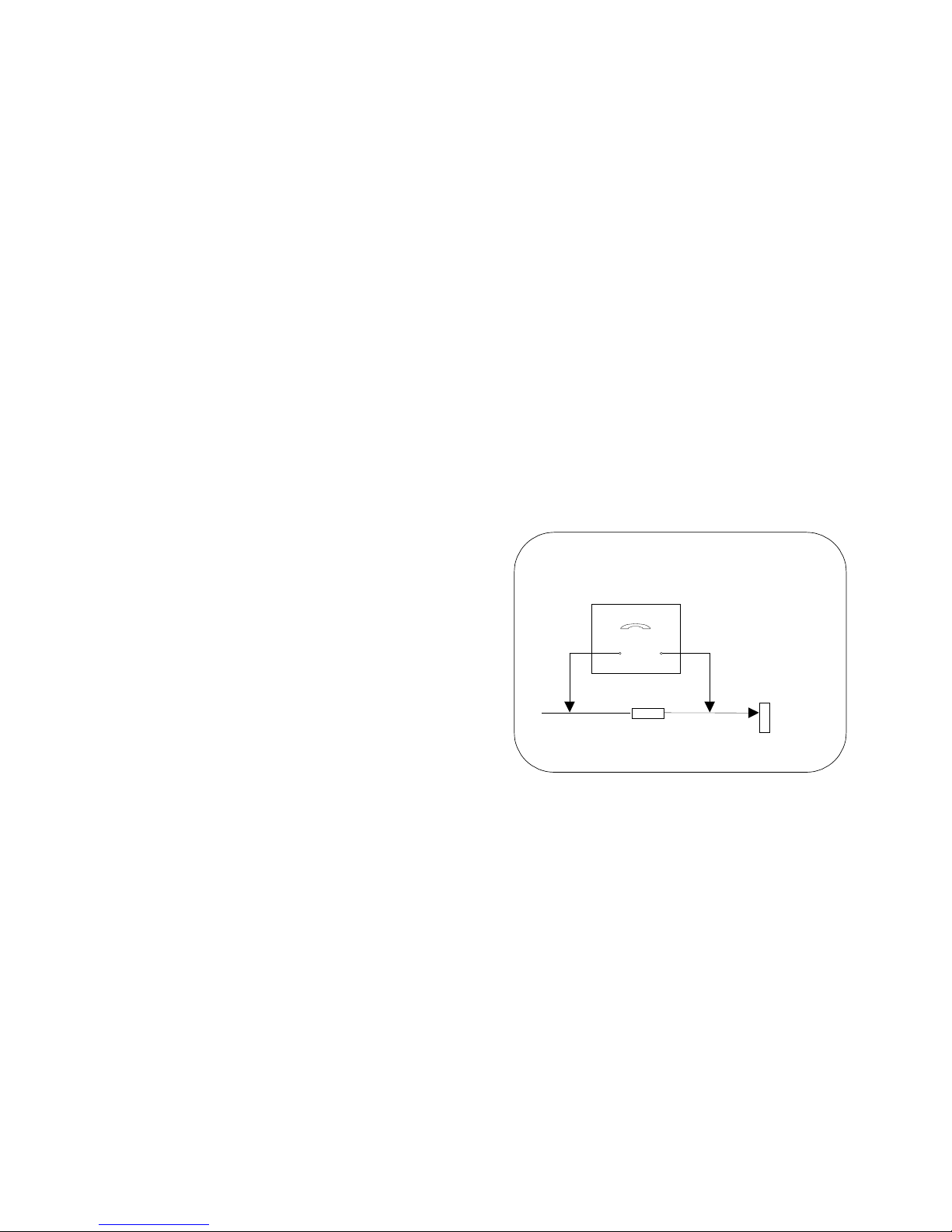
HOT CHECK CIRCUIT
a.c. VOLTMETER
WATER PIPE
(
EARTH)
TO INSTRUMENT'S EXPOSED
METALLIC PARTS
Fig. 1.
2kΩ 10 Watts
2
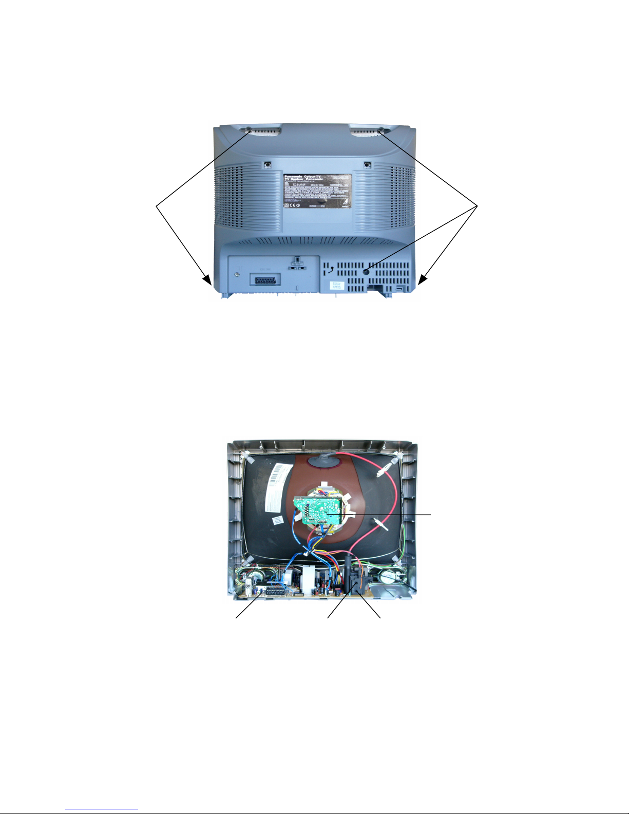
SERVICE HINTS
How to remove the rear cover
1.Remove the 5 screws as shown in Fig.2.
LOCATION OF CONTROLS
3
Fig. 2
Fig. 3
SCREWS
SCREWS
D-Board
Focus
Screen
L-Board
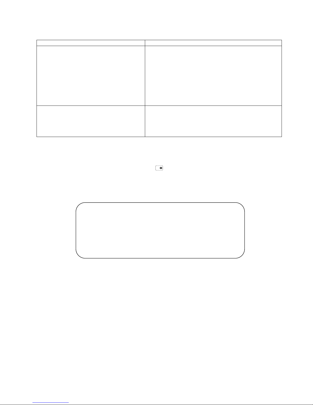
ADJUSTMENT PROCEDURE
Item / Preparation Adjustments
+B SET-UP
1. Receive a Window pattern.
2. Set the controls :
Brightness Minimum
Contrast Minimum
Confirm the following voltages:
TP4 5 ± 0,25V TP14 5 ± 0,25V
TP5* 16 ± 0,5V TP21 12,5 ± 0,5V
TP6 8 ± 0,5V TP121 180 ± 10V
TP7 9,4 ± 0,5V TP123 -14,5V ± 1V
TP8** 3,3 ± 0,2V TP124 14,5 ± 1V
TP11*** 12,4 ± 0,5V
TP12 142 ± 1,5V
* Volume to minimum
** Under shield case *** Volume to maximum
UG2 / CUT OFF
1. Receive a Window pattern.
2. Set Brightness and Contrast to minimum.
3. Set the TV into Service Mode 1.
4. Select UG2 item.
Press "+" or "-". Adjust the screen VR till LED is just switched on.
SELF CHECK
Self-check is used to automatically check the bus lines and hexadecimal code of the TV set.To enter Self-Check mode,you
must set Bass to max and Treble to min, press the STATUS button on the remote control and at the same time press
the down (-/v) button on the customer controls at the front the TV set. To exit Self Check, switch off the TV set at the power
button.
4
TX-21AP2D TX-21AP2F TX-21AP2P
TX-21AP2D/B TX-21AP2P/B
OPTION 1 1C 9C 9D
OPTION 2 10 18 10
5
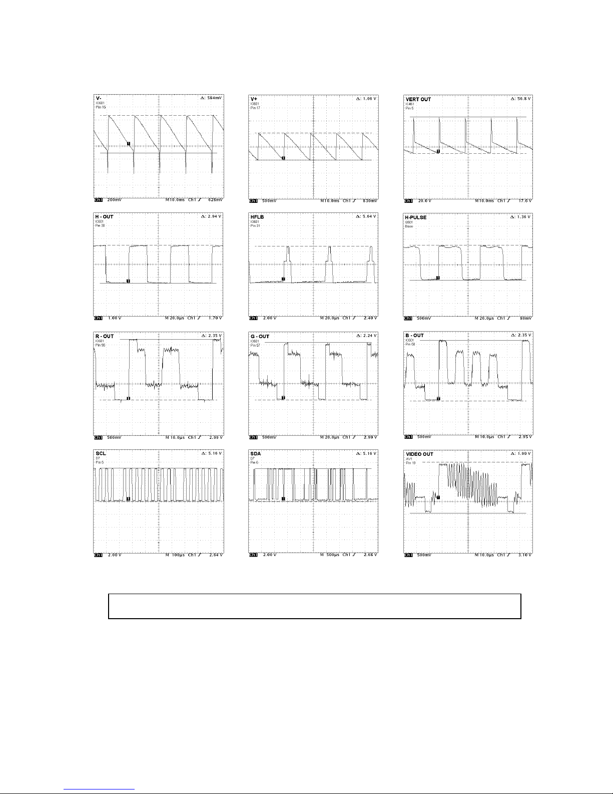
WAVEFORM PATERN TABLE
CONDITIONS: Contrast: MAX, Brightness: MID, Colour: MID, Sharpness: MID
ALIGNMENT SETTINGS
(The figures below are nominal and used for representative purposes only.)
To access Service Mode select program position 99 and set sharpness to minimum.
Press “MUTE” button on remote control and at the same time press the "∨" button on the customer controls at the front of
the TV, this will place the TV set into Service Mode1.
Press ∧ / ∨ buttons to step up / down through the functions.
Press + / - buttons to alter the function values.
Press “STR” button on the customer controls at the front of the TV after each adjustment has been made to store the
required values.
To exit Service Mode press “N” button.
Alignment Function
Setting indication
Note: All setting values are approximate
Settings / Special features
EAROM copy TV/EXT ---
UG2 LED ON/OFF LED to be just ON
Verical Slope
V-SLO
031
Optimum setting.
Vertical Position
V-POS
037
Optimum setting.
Vertical Amplitude
V-AMP
022
Optimum setting.
Horizontal Shift
H-CTR
038
Optimum setting.
R-CUT
R-CUT
022
Optimum setting.
G-CUT
G-CUT
036
Optimum setting.
R-Drive
R-DRV
040
Optimum setting.
G-Drive
G-DRV
030
Optimum setting.
B-Drive
B-DRV
31
Optimum setting.
AGC
AGC
018
Optimum setting.
Sub Colour
S-COL
28
Optimum setting.
Sub Brightness
S-BRI
022
Optimum setting.
6
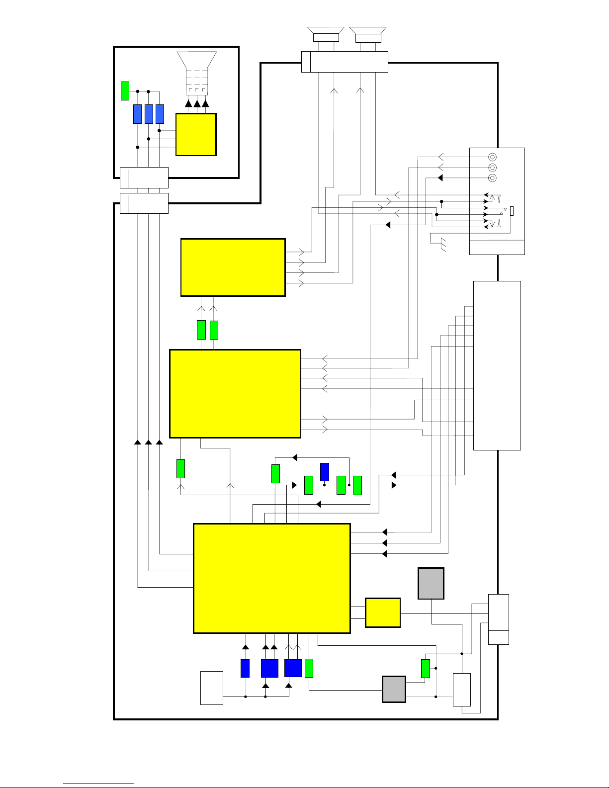
VIDEO & STEREO AUDIO & DEFLECTION BLOCK DIAGRAM
7
30 H-OUT
31 FBI
V- 16
V
+ 17
MICROPROCESSOR
DEFLECTION
1
3
4
D10
534
5
3
4
CRT
L-BOARD
IC351
12
3
B 7
G 8
R 9
Q369
D354
D355
L2
D4
IC601
18 IF1
TDA 9594
19 IF2
23 SIF1
24 SIF2
R IN 51
G IN 52
B IN 53
QIF OUT 33
58 B OUT
57 G OUT
56 R OUT
X201
X102
IF VO 38
CVBS-3 44
CVBSEXT 42
IC2101
67 QIF IN
DACM_L
28
DACM_R 27
MULTI-STANDART
SOUND
PROCESSOR
AV1 21 PIN SCART
20 VIDEO IN
15 R IN
11 G IN
19 VIDEO OUT
7 B IN
6 L IN
3 L OUT
2 R IN
1 R OUT
IC2301
AUDIO OUTPUT IC
4 R IN
2 L IN
L OUT P 12
L OUT M 11
R
L
Q2003
JK3201
V
L
R
D-BOARD
R
L
D8
2
1
4
3
R OUT M 9
R OUT P 8
SC2_IN_L 53
SC1_IN_L 56
SC2_IN_R 54
SC1_IN_R 57
SC2_OUT_L 34
SC2_OUT_R 33
Q601
Q602
180
Q603
Q2103
Q2102
TUNER
11
MONO OUT 48
60 MONO IN
VIDEO IBT
40
Q605
XF101
76 L/L’
L
R
HEADPH
Front AV2 terminal
15423
67
R
G
B
IC451
VERTICAL
71
5
DIODE
MODULATOR
T553
6
3
Q501
Q551
T551
10
 Loading...