


TRG-BO
HF SSB RADIOTELEPHONE
INSTRUCTIONMANUAL
RADIOTELEFONO DE HF SSB
MANUALDEINSTRUCCIONES
~jJiiMf~~
f~ Jti i5t aA.:f;
KENWOOD CORPORATION
(
@ 862-0485-00 (M) (MC)
09 08 07 06 05 04 03 02 01 00
I
l
HF SSB RADIOTELEPHONE
TRC-BO
INSTRUCTION MANUAL
KENWOOD CORPORATION
CONTENTS
SAFETY PRECAUTIONS 1
IMPORTANTNOTICE 1
INTRODUCTION 1
SUPPLIEDACCESSORIES 1
BASE STATIONINSTALLATION 2
ANTENNA CONNECTION 2
GROUND CONNECTION 2
DC POWERSUPPLYCONNECTION 2
ReplacingFuses 2
MOBILEINSTALLATION 3
ANTENNACONNECTION 3
DC POWERCABLE CONNECTION 3
ReplacingFuses 3
GROUND CONNECTION 3
GETTINGACQUAINTED 4
FRONTPANEL 4
REAR PANEL :: 5
DiSPLAy 6
MICROPHONE 7
OPERATINGBASICS 7
SWITCHINGPOWERON/OFF ; 7
ADJUSTINGVOLUME 7
ADJUSTINGSQUELCH 7
SELECTINGACHANNEL 8
SELECTINGA MODE 8
TRANSMITTING 8
ChangingTransmitPower 8
VoiceModes 8
VOX (Voice-operatedTransmit) 8
CW Mode 9
DATAOPERATION 9
FSK MODE 9
AFSK MODE 9
MENU SETUP 10
CHANGINGMENUSETTINGS 10
MENUCONFIGURATION 10
MEMORYBACKUP 10
SCAN 11
BUSYFREQUENCYSTOP 11
Scan ResumeMethods 11
CHANNEL LOCKOUT 11
STARTING/STOPPINGSCAN 11
NOISE BLANKER 11
CLARIFIER 11
KPE-1SELECTIVECALL UNIT(OPTIONAL) 11
MANUALCALLING 12
MEMORYCALLING 12
RECEiViNG 12
CHANGING IDENTIFICATIONCODES 13
CHANGINGCHARACTERMESSAGES 13
AUTOMATICANTENNATUNER 13
PRESETTING(KAT-2INTERNALTUNER) 13
KAT-2INTERNALTUNER (OPTIONAL) 13
KAT-1/MAT-100EXTERNALTUNER
(OPTIONAL) 13
COMPUTER RADIOTELEPHONE
INTERFACE 14
COMMUNICATIONPARAMETERS 14
HARDWAREDESCRIPTION 14
MAINTENANCE.. 15
SERVICE 15
SERVICENOTE 15
CLEANING 15
TROUBLESHOOTING 16
ACCESSORYCONNECTIONS 17
COMPUTERINTERFACE(ACC 1) 17
PC-1APHONEPATCH
CONTROLLER(ACC2) 17
ANTENNATUNER (AT) 17
DATAEQUIPMENTINTERFACE(ACC2) 18
CHANNELMEMO 19
APPENDiX A1
CONTROLOPERATION A1
COMMANDS A1
COMMANDDESCRIPTION A1
PARAMETERDESCRIPTION A1
TERMINATOR :..A2
TYPESOF COMMANDS A2
COMPUTERCONTROLCOMMANDS A3
ERRORMESSAGES A3
COMMANDUSE PRECAUTIONS A3
READINGCOMMANDTABLES A4
COMMANDTABLES A4
SAFETYPRECAUTIONS
It is important that the operator understands and is
aware of hazards common to the operation of any
radiotelephone.
WARNING!
1 EXPLOSIVEATMOSPHERES
(GASES, DUST,FUMES,ETC.)
Turnoff and do not operatethe radiotelephonewhile
taking on fuel, or while parked in gasolineservice
stations. Do notcarry sparefuel containersinthe trunk
of your vehicle ifthe radiotelephoneis mountedin the
trunk area.
2 INJURY FROMRADIO FREQUENCY
TRANSMISSIONS
Do not operate the radiotelephone when anyone is
touching the antenna, or when anyone is standing within
two to three feet of the antenna, to avoid the possibility
of radio frequency burns or related physical injury.
3 DYNAMITE BLASTING CAPS ...
Transmitter operation can cause dynamite blasting caps
to explode if you operate within 500 feet of the blasting
caps. Turn off and do not operate the radiotelephone in
an area where blasting is in progress, or where "TURN
OFF TWO-WAY RADIO" signs have been posted. If
you are transporting blasting caps in your vehicle, make
certain they are carried in a closed metal box having a
padded interior. Do not transmit during the time that the
caps are being placed into or removed from this
container.
IMPORTANTNOTICE
Government law prohibits the operation of unlicensed
radio transmitters within the territories under
government control. Illegal operation is punishable by
fine or imprisonment or both.
Refer service to a qualified licensed or certified
technician only.
INTRODUCTION
All KENWOOD radiotelephones incorporate the latest in
advanced technology, providing communications that
can be counted on to keep vehicles and personnel
operating at peak efficiency.
The easy-to-operate TRC-80 radiotelephone continues
the KENWOOD tradition of dependable
communications. When combined with the optional
KPE-1 Selective Call Unit, the TRC-80 allows full
flexibility for signaling and communicating with specific
stations or groups of stations.
SUPPLIEDACCESSORIES
Note: The followinginstructionsare for use by your KENWOOD
Dealeronly (eitheran authorizedKENWOOD servicefacility or the
factory).
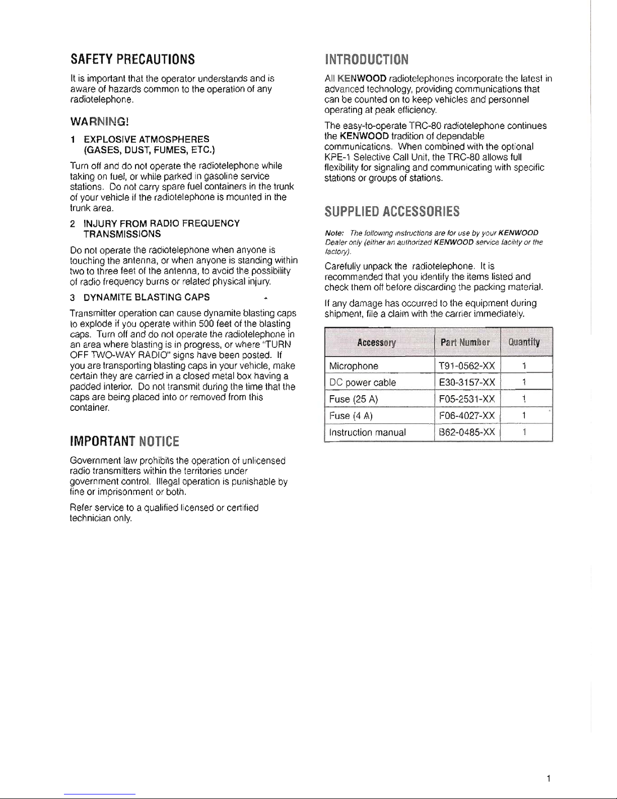
Carefully unpack the radiotelephone. Itis
recommended that you identify the items listed and
check them off before discarding the packing material.
If any damage has occurred to the equipment during
shipment, file a claim with the carrier immediately.
1
Accessory
PartNumber
Quantity
Microphone
T91-0562-XX 1
DC power cable
E30:.3157-XX 1
Fuse (25 A)
F05-2531-XX 1
Fuse (4 A)
F06-4027-XX 1
.
Instruction manual B62-0485-XX 1
BASESTATIONINSTALLATION
ANTENNACONNECTION
The type of the antenna system,consistingof the
antenna,ground,and feed line,will greatlyaffectthe
successfulperformanceof the radiotelephone. Usea
properlyadjusted50 Q antennaof goodqualityto let
your radiotelephoneperformat its best. Usea
good-quality50 Q coaxialcableand a first-quality
connectorforthe connection. Matchthe impedanceof
the coaxialcable andantennaso that the SWR is 1.5:1
or less. Allconnectionsmustbe clean and tight.
Whilethe radiotelephone'sprotectioncircuitwill activate
ifthe SWR is greaterthan 2.5:1,do not relyon
protectionto compensatefor a poorlyfunctioning
antennasystem. HighSWR will cause thetransmit
outputto drop,and may leadto radiofrequency
interferenceto consumerproductssuchas stereo
receiversand televisions. Youmay even interferewith
your own radiotelephone. Reportsthat yoursignalis
garbledor distorted,especiallyat peak modttlation,may
indicatethat your antennasystem is notefficiently
radiatingthe radiotelephone'spower. Ifyou feela tingle
fromthe radiotelephone'scabinetor the microphone's
metalfittings whenyou modulate,you can becertain
that, at the least,your coax connectoris loose at the
rearof the radioand, atthe worst,your antennasystem
is not efficientlyradiatingpower.
CAUTION:
. Transmittingwithoutfirstconnectinganantennaorothermatched
load may damagethe radiotelephone. Always connect the
antenna to theradiotelephonebefore transmitting.
. Usea lightning a"estor toprevent fire, electricshock, or damage
to theradiotelephone.
GROUNDCONNECTION
Atthe minimum,a good DCground is requiredto
prevent such dangers as electricshock. Forsuperior
communicationsresults, a good RFground is required,
against whichthe antenna systemcan operate. Bothof
these conditionscan be met by providinga good earth
groundforyourstation. Buryone or more groundrods,
or a largecopper plate underthe ground,and connect
thisto the radiotelephoneGNDterminal. Use heavy
gauge wireor a copper strap, cut as short as possible,
forthis connection. Allconnections mustbe clean and
tight.
To antenna
-
Earth ground
TRC-80
2
DCPOWERSUPPLYCONNECTION
Inorderto use thisradiotelephone,youwillneed a
separate 13.6V DCpowersupplythat must be
purchased separately. DONOTdirectlyconnect the
radiotelephoneto an ACoutlet! Usethe supplied DC
powercable to connect the radiotelephoneto a
regulatedpowersupply. Donot substitutea cable with
smallergauge wires. The current capacity of your
powersupplymust be 20.5Aor more.
CAUTION:
. BeforeconnectingtheDCpowersupplytotheradiotelephone,be
suretoswitchtheradiotelephoneandtheDCpowersupplyOFF.
. DonotplugtheDCpowersupplyintoanACoutletuntilyou
makeallconnections.
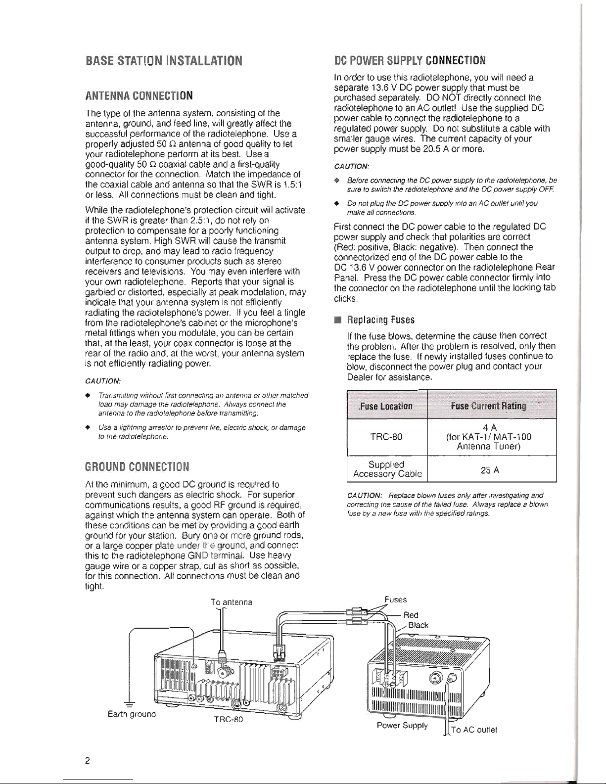
Firstconnect the DCpowercable to the regulated DC
powersupplyandcheckthat polaritiesare correct
(Red: positive, Black: negative). Then connect the
connectorized end of the DC power cable to the
DC 13.6 V power connector on the radiotelephone Rear
Panel. Press the DC power cable connector firmlyinto
the connector on the radiotelephone until the locking tab
clicks.
. ReplacingFuses
Ifthe fuse blows, determine the cause then correct
the problem. After the problem is resolved, only then
replace the fuse. Ifnewly installed fuses continue to
blow,disconnect the power plug and contact your
Dealer for assistance.
CAUTION: Replace blownfuses only after investigating and
correcting the cause of the failed fuse. Always
replacea blown
fuseby a new fuse withthespecified ratings.
Fuses
Power Supply
To AC outlet
.FuseLocation
FuseCurrentRating
4A
TRC-BO
(for KAT-1/ MAT-100
Antenna Tuner)
Supplied
25A
Accessory Cable
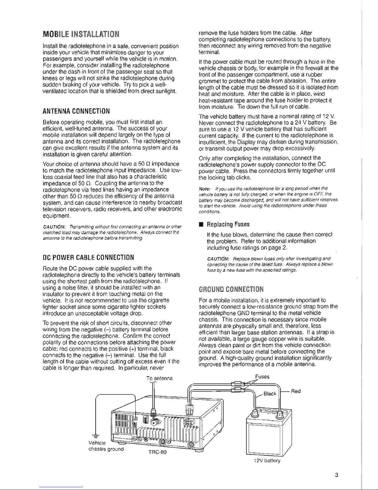
MOBilEINSTAllATION
Install the radiotelephone in a safe, convenient position
inside your vehicle that minimizes danger to your
passengers and yourself while the vehicle is in motion.
For example, consider installing the radiotelephone
under the dash in front of the passenger seat so that
knees or legs willnot strike the radiotelephone during
sudden braking of your vehicle. Try to picka well-
ventilated location that is shielded from direct sunlight.
ANTENNACONNECTION
Before operating mobile, you must first install an
efficient, well-tuned antenna. The success of your
mobile installation willdepend largely on the type of
antenna and its correct installation. The radiotelephone
can give excellent results ifthe antenna system and its
installation is given careful attention.
Your choice of antenna should have a 50 Q impedance
to match the radiotelephone input impedance. Use low-
loss coaxial feed linethat also has a characteristic
impedance of 50 Q. Coupling the antenna to the
radiotelephone via feed lines having an impedance
other than 50 Q reduces the efficiency of the antenna
system, and can cause interference to nearby broadcast
television receivers, radio receivers, and other electronic
equipment.
CAUTION: Transmitting without first connecting an antenna or other
matched load may damage the radiotelephone. Always connect the
antenna to the radiotelephone before transmitting.
DCPOWERCABLECONNECTION
Route the DC power cable supplied with the
radiotelephone directly to the vehicle's battery terminals
using the shortest path from the radiotelephone. If
using a noise filter,it should be installed with an
insulator to prevent it from touching metal on the
vehicle. Itis not recommended to use the cigarette
lighter socket since some cigarette lighter sockets
introduce an unacceptable voltage drop.
To prevent the risk of short circuits, disconnect other
wiring from the negative H battery terminal before
connecting the radiotelephone. Confirm the correct
polarity of the connections before attaching the power
cable; red connects to the positive (+)terminal, black
connects to the negative (-) terminal. Use the full
length of the cable without cutting offexcess even ifthe
cable is longer than required. Inparticular, never
To antenna
removethe fuse holdersfrom the cable. After
completing radiotelephone connections to the battery,
then reconnect any wiring removed from the negative
terminal.
Ifthe power cable must be routed through a hole in the
vehicle chassis or body, for example inthe firewall at the
front of the passenger compartment, use a rubber
grommet to protect the cable from abrasion. The entire
length of the cable must be dressed so it is isolated from
heat and moisture. After the cable is in place, wind
heat-resistant tape around the fuse holder to protect it
from moisture. Tie down the full run of cable.
The vehicle battery must have a nominal rating of 12 V.
Never connect the radiotelephone to a 24 V battery. Be
sure to use a 12 V vehicle battery that has sufficient
current capacity. If the current to the radiotelephone is
insufficient, the Display may darken during transmission,
or transmit output power may drop excessively.
Only after completing the installation, connect the
radiotelephone's power supply connector to the DC
power cable. Press the connectors firmly together until
the locking tab clicks.
Note: Ifyou use the radiotelephone for a long period when the
vehicle battery is not fully charged, or when the engine is OFF, the
battery may become discharged, and will not have sufficient reserves
to start the vehicle. Avoid using the radiotelephone under these
conditions.
. ReplacingFuses
If the fuse blows, determine the cause then correct
the problem. Refer to additional information
including fuse ratings on page 2.
CAUTION: Replace blown fuses only after investigating and
correcting the cause of the failed fuse. Always replace a blown
fuse by a new fuse with the specified ratings.
GROUNDCONNECTION
Fora mobileinstallation,itis extremelyimportantto
securelyconnect a low-resistanceground strap fromthe
radiotelephoneGNDterminalto the metalvehicle
chassis. This connectionis necessary since mobile
antennas are physicallysmalland, therefore, less
efficientthan largerbase stationantennas. Ifa strap is
notavailable,a largegauge copper wireissuitable.
Alwaysclean paintor dirtfromthe vehicleconnection
pointand expose bare metalbefore connectingthe
ground. Ahigh-qualitygroundinstallationsignificantly
improvesthe performanceofa mobileantenna.
Fuses
-
Vehicle
chassis ground
TRC-BO
=
Red
12V battery
3
GETTINGACQUAINTED
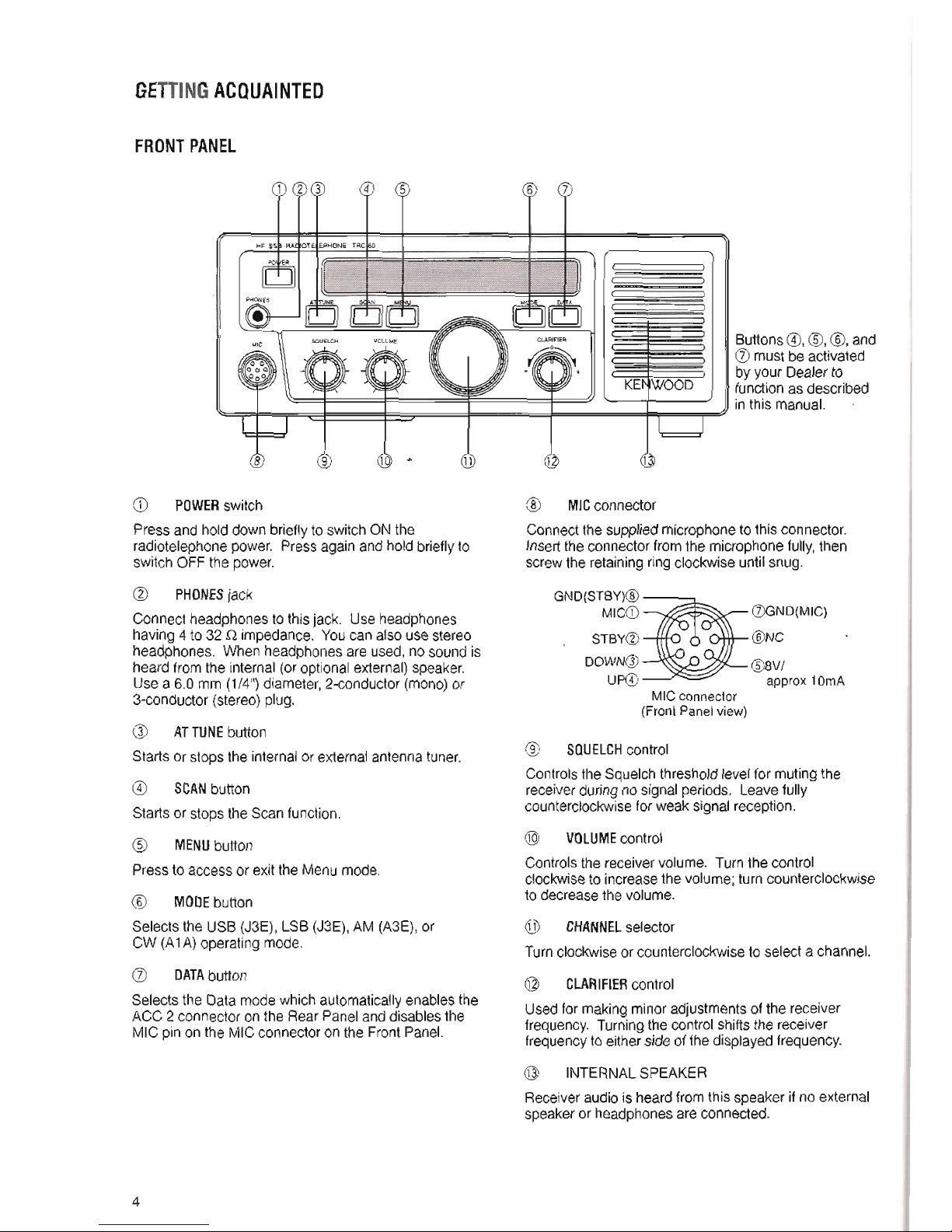
FRONTPANEL
5
CD POWER
switch
Press and hold down briefly to switch ON the
radiotelephone power. Press again and hold briefly to
switch OFF the power.
@ PHONESjack
Connect headphones to this jack. Use headphones
having 4 to 32 Q impedance. You can also use stereo
headphones. When headphones are used, no sound is
heard from the internal (or optional external) speaker.
Use a 6.0 mm (1/4") diameter, 2-conductor (mono) or
3-conductor (stereo) plug.
ATTUNE button
Starts or stops the internal or external antenna tuner.
SCAN button
Starts or stops the Scan function.
MENUbutton
Press to access or exit the Menu mode.
@ MODEbutton
Selects the USB (J3E), LSB (J3E), AM (A3E), or
CW (A1A) operating mode.
(j) DATAbutton
Selects the Data mode which automatically enables the
ACC 2 connector on the Rear Panel and disables the
MIC pin on the MIC connector on the Front Panel.
4
6
Buttons @, CID,@, and
(j) must be activated
by your Dealer to
function as described
in this manual.
@ MICconnector
Connect the supplied microphone to this connector.
Insert the connector from the microphone fully, then
screw the retaining ring clockwise until snug.
GND(STBY)@
MICCD
B=
0GND(MIC)
. STBY@ @NC'
DOWNeJ) @8V/
UP@) approx 10mA
MIC connector
(Front Panelview)
@ SQUELCHcontrol
Controlsthe Squelchthresholdlevelfor mutingthe
receiverduringno signalperiods. Leavefully
counterclockwiseforweak signalreception.
@ VOLUMEcontrol
Controlsthe receivervolume. Turnthe control
clockwiseto increasethe volume;turn counterclockwise
to decreasethe volume.
@ CHANNELselector
Turnclockwiseor counterclockwiseto selecta channel.
CLARIFIERcontrol
Used for making minor adjustments of the receiver
frequency. Turning the control shifts the receiver
frequency to either side of the displayed frequency.
dJ INTERNALSPEAKER
Receiver audio is heard from this speaker if no external
speaker or headphones are connected.
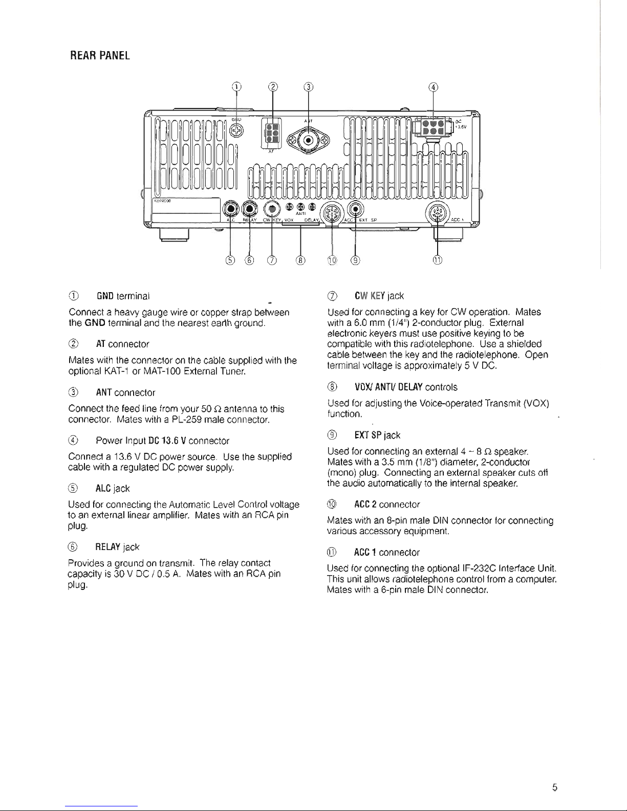
REARPANEL
CD GNDterminal
...
Connecta heavygaugewire or copperstrapbetween
the GND terminaland the nearestearthground.
(g) ATconnector
Mateswiththe connectoron the cablesuppliedwith the
optional KAT-1or MAT-100ExternalTuner.
CID ANTconnector
Connectthe feed line fromyour 50 Q antennato this
connector. Mateswith a PL-259maleconnector.
@ Power InputDC13.6Vconnector
Connecta 13.6V DC powersource. Usethe supplied
cablewith a regulatedDC powersupply.
@ ALCjack
Usedfor connectingthe Automatic LevelControlvoltage
to anexternal linearamplifier. Mateswith an RCApin
plug.
@ RELAYjack
Providesa ground ontransmit. The relaycontact
capacity is 30 V DC / 0.5 A. Mateswithan RCApin
plug.
(]) CWKEYjack
Usedfor connectinga key for CW operation. Mates
with a6.0 mm (1/4")2-conductorplug. External
electronickeyersmust use positivekeyingto be
compatiblewith this radiotelephone. Use a shielded
cablebetweenthe keyand the radiotelephone. Open
terminalvoltageis approximately5 V DC.
@ VOX!ANTI!DELAYcontrols
Usedfor adjustingthe Voice-operatedTransmit(VOX)
function.
@ EXTSPjack
Usedfor connectingan external4 -8Q speaker.
Mateswith a 3.5 mm (1/8")diameter,2-conductor
(mono)plug. Connectingan externalspeakercuts off
the audioautomaticallyto the internalspeaker.
@> ACC2connector
Mateswith an 8-pinmale DINconnectorfor connecting
variousaccessoryequipment.
@ ACC1 connector
Usedfor connectingthe optionallF-232C InterfaceUnit.
This unit allowsradiotelephonecontrolfrom a computer.
Mateswith a 6-pinmale DINconnector.
5
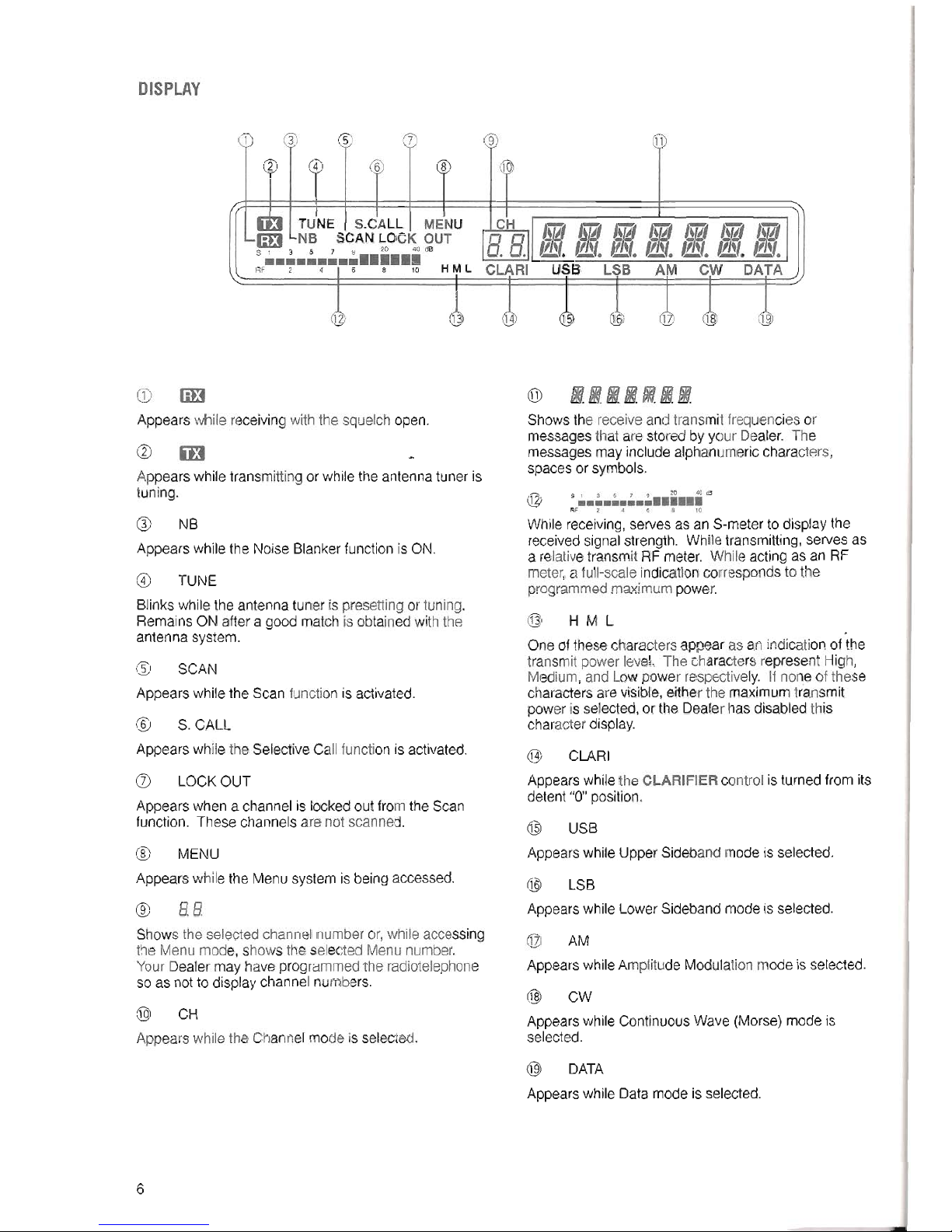
DISPLAY
5 7
4
6 8
TUNE I S.CALL I MENU
EElLNB SCAN LOCK OUT
51 3 5 7 9 20 40 dB
H M LRF 2 4 I 6 8 10
CD EEl
Appears while receiving with the squelch open.
m
Appears while transmitting or while the antenna tuner is
tuning.
NB
Appears while the Noise Blanker function is ON.
TUNE
Blinks while the antenna tuner is presetting or tuning.
Remains ON after a good match is obtained with the
antenna system.
SCAN
Appears while the Scan function is activated.
@
S.CALL
Appears while the Selective Call function is activated.
LOCKOUT
Appears when a channel is locked out from the Scan
function. These channels are not scanned.
@
MENU
Appears while the Menu system is being accessed.
@
88
Shows the selected channel number or, while accessing
the Menu mode, shows the selected Menu number.
Your Dealer may have programmed the radiotelephone
so as not to display channel numbers.
@ CH
Appearswhile the Channelmode is selected.
6
9
:11
JQ
@ IIIIIII
Shows the receive and transmit frequencies or
messages that are stored by your Dealer. The
messages may include alphanumeric characters,
spaces or symbols.
S1 3 5 7 SI 20 40cS
...............
AF 2 .. e 8 10
While receiving, serves as an S-meter to display the
received signal strength. While transmitting, serves as
a relative transmit
RFmeter. While acting as an RF
meter, a full-scale indication corresponds to the
programmed maximum power.
@ H M L
One of thesecharactersappear asan indicationof the
transmitpower level. The charactersrepresent High,
Medium,and Low power respectively. If none of these
charactersarevisible,eitherthe maximumtransmit
poweris selected,orthe Dealerhas disabledthis
characterdisplay.
@ CLARI
Appearswhilethe CLARIFIER control is turnedfrom its
detent"0"position.
@ USB
Appears while Upper Sideband mode is selected.
@ LSB
Appearswhile LowerSidebandmodeis selected.
@ AM
AppearswhileAmplitudeModulationmode is selected.
@ CW
Appearswhile ContinuousWave (Morse)mode is
selected.
@ DATA
Appearswhile Datamode is selected.
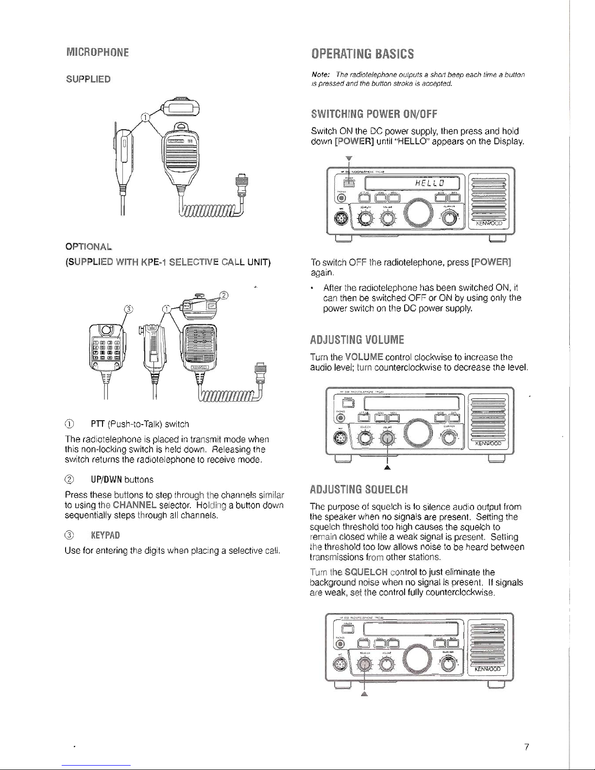
MICROPHONE
SUPPLIED
o
OPTIONAL
(SUPPLIEDWITH KPE.1 SELECTIVECALL UNIT)
CD PTT(Push-to- Talk) switch
The radiotelephone is placed in transmit mode when
this non-locking switch is held down. Releasing the
switch returns the radiotelephone to receive mode.
@ UP/DWNbuttons
Pressthese buttonsto stepthrough thechannelssimilar
to usingthe CHANNELselector. Holdinga buttondown
sequentiallysteps through allchannels.
KEYPAD
Use for entering the digits when placing a selective call.
OPERATINGBASICS
Note: The radiotelephone outputs a short beep each time a button
ispressed and the buttonstroke is accepted.
SWITCHINGPOWERON/OFF
Switch ON the DC power supply, then press and hold
down [POWER] until "HELLO" appears on the Display.
)
DD
-6.
1<EJIiWOOD
To switch OFF the radiotelephone, press [POWER]
again.
. After the radiotelephone has been switched ON, it
can then be switched OFF or ON by using only the
power switch on the DC power supply.
ADJUSTINGVOLUME
Turn the VOLUME control clockwise to increase the
audio level; turn counterclockwise to decrease the level.
KENWOOD
ADJUSTINGSQUELCH
The purpose of squelch is to silence audio output from
the speaker when no signals are present. Setting the
squelch threshold too high causes the squelch to
remain closed while a weak signal is present. Setting
the threshold too low allows noise to be heard between
transmissions from other stations.
Turn the SQUELCH control to just eliminate the
background noise when no signal is present. If signals
are weak, set the control fully counterclockwise.
KENWOOD
7
 Loading...