


INSTRUCTION MANUAL
SPECIALIZED COMMUNICATIONS
144/440 MHz FM DUAL BANDER
TM-D700A
144/430 MHz FM DUAL BANDER
TM-D700A
144/430 MHz FM DUAL BANDER
TM-D700E
KENWOOD CORPORATION
© B62-1273-20 (K,E,M)
09 08 07 06 05 04 03 02 01

CONTENTS
CHAPTER 1 PACKET OPERA TION
CONNECTING WITH A PERSONAL COMPUTER .... 2
OPERATING TNC .....................................................3
PREPARATION FLOW .............................................. 4
SELECTING DATA BAND.......................................... 5
DCD SENSE ............................................................. 5
CHAPTER 2 DX PACKETCLUSTERS MONITOR
CHAPTER 3 PACSATs
CHAPTER 4 AUTOMATIC PACKET/ POSITION REPORTING
SYSTEM
PACKET PATH AND DIGIPEATER ............................ 9
CONNECTING WITH A GPS RECEIVER ................ 10
OPERA TION FLOW ................................................ 11
ADJUSTING THE INTERNAL CLOCK..................... 12
Setting Time........................................................ 12
Setting Date........................................................ 12
Setting UTC Offset.............................................. 13
SELECTING DATA BAND........................................ 13
SELECTING PACKET TRANSFER RATE ............... 13
RECEIVING APRS DAT A......................................... 14
ACCESSING RECEIVED APRS DATA .................... 15
PROGRAMMING A CALL SIGN............................... 17
SELECTING YOUR STATION ICON........................ 18
PROGRAMMING POSITION DATA ......................... 19
SELECTING A POSITION COMMENT .................... 20
STORING STATUS TEXT ........................................ 21
PROGRAMMING A GROUP CODE ......................... 22
PROGRAMMING A PACKET PATH ......................... 23
SELECTING PACKET TRANSMIT METHOD .......... 25
SELECTING PACKET TRANSMIT INTER VAL.........25
SELECTING STA TUS TEXT TRANSMIT RATE ....... 25
RESTRICTING RECEPTION OF APRS DATA.........26
PROGRAMMING POSITION AMBIGUITY............... 26
PACKET MONITOR DISPLAY ................................. 26
SETTING AS A DIGIPEATER .................................. 27
CHAPTER 5 APRS MESSAGE
OPERA TION FLOW ................................................ 28
RECEIVING A MESSAGE ....................................... 29
ENTERING A MESSAGE.........................................30
ACCESSING RECEIVED APRS MESSAGES ......... 31
TRANSMITTING A MESSAGE ................................ 32
AUTO ANSWER REPLY.......................................... 33
PROGRAMMING A GROUP CODE ......................... 34
CHAPTER 6 SLOW-SCAN TELEVISION (SSTV) WITH
VC-H1
CONNECTION WITH VC-H1 ................................... 35
ENTERING CALL SIGN/ MESSAGE/ RSV .............. 36
SELECTING COLOR FOR CALL SIGN/
MESSAGE/ RSV ..................................................... 37
EXECUTING SUPERIMPOSITION.......................... 37
SSTV MODE CHANGE ........................................... 38
VC-H1 CONTROL ................................................... 38
CHAPTER 7 TROUBLESHOOTING
APPENDIX
INDEX
1
2
3
4
5
6
7
i

MIC KEYPAD DIRECT ENTRY (MC-53DM ONLY)
1 qz1QZ 6 mno6MNO
2 abc2ABC 7 p r s7PRS
3 def3DEF 8 tuv8TUV
4 ghi4GHI 9 wxy9WXY
5 jkl5JKL 0
ecapS
0
#
?!' .,–/&#%()<>;:
"@
The keypad on the MC-53DM allows you to enter a call
sign, message, or other character strings. The types of
characters which you can enter differ depending on the
purpose of an entry. Each press of a Mic key switches
entry of characters as shown in the tables. You can
always use Mic [A] as [
aa
a], [B] as [
aa
and [D] as [OK].
For a call sign {pages 17/ 30}, group code {pages 22/ 34},
packet path {pages 23/ 27}, and SSTV string {page 36}:
1 QZ1 7 PRS7
2 ABC2 8 TUV8
3 DEF3 9 WXY 9
bb
b], [C] as [DEL],
bb
For a memory name {page 19}, status text {page 21},
and message {pages 30/ 33}:
4 GH I 4 0 0
5 JKL5
#
6 MNO6 !3?
1
Packet path and message/ bulletin group codes only
2
Message group code only
3
SSTV string only
12/3
–,
3
ii

PACKET OPERATION
Packet is a unit of data transmitted as a whole from one
computer to another on a network. Packets can be
transmitted on radio waves as well as on
communications lines. Besides a transceiver and a
computer, all you need is a terminal node controller
(TNC). A TNC converts packets to audio tones and vice
versa as one of its tasks. This transceiver has a built-in
TNC.
A variety of packet applications developed by hams
include packet bulletin board systems (PBBSs). PBBSs
are created and maintained by volunteers called System
Operators (SysOp). You may access one of your local
PBBSs to send e-mail, download a file, or obtain various
useful information. Thousands of PBBSs, which have
formed a worldwide network, relay e-mail to its intended
destination around the world.
PBBS
When you access a local PBBS for the first time, you
often need to register as a new user. After you are
successfully registered, it will then be available as your
home PBBS. E-mail addressed to you will be hold under
a directory, called a mailbox, on your home PBBS.
To send e-mail, you must designate the address of a
recipient, using his (or her) call sign and the call sign of
his (or her) home PBBS; ex. KD6NUH@KJ6HC. In this
example, e-mail is addressed to KD6NUH whose home
PBBS is KJ6HC. If your home PBBS cannot find KJ6HC
in its address file to forward your mail, you must
designate the address in more detail. You may enter
“KD6NUH@KJ6HC.#ABC.CA”, or
“KD6NUH@KJ6HC.#ABC.CA.USA”, or up to
“KD6NUH@KJ6HC.#ABC.CA.USA.NA”, as necessary.
The complete address of a recipient living in the U.S., for
example, should include an appropriate region code
(preceded by a #), state, country, and continent
abbreviations as above.
For further information, consult reference books which
should be available at any store that handles Amateur
Radio equipment. If you are living in the U.S., refer to
the ARRL Repeater Directory for packet frequencies.
Web pages relating to Packet will also be helpful. On
one of the Internet search engines, you may use “Packet
Radio" as a key word to find those Web pages.
Note: If there is an amateur radio club in your area, consider becoming a
member. You can learn more in an hour from experienced hobbyists,
than in a month of independent research. Ask on the local repeaters, or
contact your national amateur radio organization (in the U.S., the ARRL)
for information on local amateur radio clubs. You'll be glad you did.
1
1

CONNECTING WITH A PERSONAL COMPUTER
.oNniP emaNniP noitcnuF
1DKP
tupniatadtekcaP
•reviecsnartotCNTmorfatadXT
2EDDKProfdnuorG
3SKP
ybdnatstekcaP
•ehttibihniotnipsihtesunacCNT
elihwtupnienohporcimreviecsnart
.slangistekcapgnittimsnart
49RP
atadspb0069detcetedfotuptuO
Vm005(
P-P
k01, Ω)
•rofnipnommocasasnoitcnufoslA
.tuptuoatadspb0069dnaspb0021
51RP
atadspb0021detcetedfotuptuO
Vm005(
P-P
k01, Ω)
6CQS
tuptuolortnochcleuqS
•elihwgnittimsnartatadCNTstibihnI
.neposihcleuqsreviecsnart
•eciovotecnerefretnistneverP
emasehtnosnoitacinummoc
.seirterstneverposlA.ycneuqerf
•leveLtuptuO
)hgiH(V5+:hcleuqsnepO
)woL(V0:hcleuqsdesolC
Use a commercially available RS-232-C straight cable to
connect the transceiver to a personal computer. This
1
transceiver has a DB-9 male connector on the front of
the main unit.
Note: Turn OFF the transceiver power before making the connections.
.oNniP
1DCD—
2DXRatadXT
3DXTatadXR
4RTDydaeRlanimreTataD
5DNGdnuorglangiS
6RSDydaeRteSataD
7STRelbaneXR
8STCelbaneXT
9IR—
On Computer
T o connect an external TNC to the transceiver, use an
optional PG-5A cable. The DAT A connector on the front of
the main unit mates with a 6-pin mini DIN plug on this cable.
emaNniP
)retupmoC:feR(
GND
2
noitcnuF
)007D-MT:feR(
On TM-D700
Note:
◆
If the external TNC has a common pin for 1200 bps and 9600 bps
data input, connect this pin to the DA TA connector PR9 pin. Shorting
the PR9 and PR1 pins will cause the TNC to malfunction.
◆
If DC voltage is input to the PR1 pin, the external TNC may not
function. If this problem happens, add a 10 µF capacitor between the
PR1 pin and the TNC. Be careful with the polarity of the capacitor.

OPERATING TNC
rotacidnI sutatS
TKPCNT.edomtekcaPnisiCNTehT
ATS
ehtniniamerllitsdettimsnartebotstekcaP
.reffub
NOC
tegratehthtiwnoitcennocnisiCNTehT
.noitats
DOBM
desseccagniebsiCNTehtnixobliamehT
.noitatsrehtoehtybdetcennocro
LIAM
liamsdlohCNTehtnixobliamehT
.uoyotdesserdda
0021detcelesetarrefsnartspb0021
0069detcelesetarrefsnartspb0069
This transceiver has a built-in TNC which conforms to
the AX.25 protocol. This protocol is used for
communications between TNCs. The TNC accepts data
from your personal computer and assembles it into
packets. It then converts packets to audio tones which
the transceiver can transmit. The TNC also takes audio
tones from the transceiver, converts them to data for the
computer, and checks for errors in the data.
The TNC mainly functions in Command or Converse
mode. First learn the difference between these two
modes.
• Command mode
When you select Packet mode, the TNC enters this
mode. A “cmd:” prompt appears on the computer
screen. You can type commands from the computer
keyboard to change the settings on the TNC. When
in Converse mode, press [Ctrl]+[C] on the keyboard
to restore the Command mode.
• Converse mode
The TNC enters this mode when a linkage with the
target station is established. On the computer
keyboard, type an appropriate command and if
necessary a message, then press [Enter] or
[Return]. What you type is converted into packets
and transmitted over the air. When in Command
mode, type CONVERSE to restore the Converse
mode; you can also type CONV or K instead.
For the commands supported by the built-in TNC, see
“TNC COMMANDS LIST” on page 41.
The following indicators appear on the transceiver
display to show the current TNC status:
The built-in TNC includes a simple mailbox to directly
receive mail from other stations; the mailbox holds up to
approximately 110 kilobytes (KB) of information. You
can read mail from the mailbox by sending a command
from your personal computer {page 47}.
Note:
◆
Not all functions available via conventional TNCs are supported by
the TNC built in this transceiver.
◆
The built-in TNC could be automatically reinitiated when its
malfunction is detected; this does not designate that the transceiver
is defective.
◆
To distinguish your various stations or nodes, you can have up to 15
Secondary Station IDentifiers (SSIDs); ex. WD6BQD-1 to WD6BQD-
15. You always have to put a dash between your call sign and SSID
number.
◆
Packet operation, easily affected by transmit and receive conditions,
requires a full-scale S-meter reading for reliable communication.
When the S-meter reads less than maximum during 9600 bps
operation, communication errors are frequent.
1
3

PREPARATION FLOW
The following steps should guide you to a good start of
packet operation. The shaded steps indicate operations
1
on your personal computer. First connect the
transceiver to the personal computer {page 2}.
Note: You must not change the default (9600 bps) in Menu 1–9–5 (COM
PORT).
q Install an appropriate terminal program on the
personal computer.
• A variety of freeware or shareware programs can be
obtained in various ways. Consult your reference
material or other “packeteers”.
w Initiate the terminal program and set the following
parameters on the personal computer:
• Transfer rate (TNC <–> Computer): 9600 bps
• Data length: 8 bit
• Stop bit: 1 bit
• Parity: Non
• Flow control: Hardware
e Access Menu 1–6–1 to select band A or B as the
data band {page 5}.
r Press [F] (1 s), [TNC], then [F] (1 s), [TNC] again
to enter Packet mode.
•“TNC PKT” should appear.
t To select 9600 bps as the transfer rate from/to the
target station, type HBAUD (or HB) 9600 and
press [Enter] or [Return]. The default is
1200 bps.
• You must select the same transfer rate as the target
station.
y Type MYCALL (or MY) then your call sign (9 digits
max.) and press [Enter] or [Return] to set your
call sign on the TNC.
• You cannot use the default setting (NOCALL).
u Tune to an appropriate frequency.
• First you may want to monitor packets which are
transmitted among other stations. When packets
are received, text appears and the computer screen
scrolls.
i To connect with the target station, type
CONNECT (or C) then its call sign and press
[Enter] or [Return].
• When a linkage is established, a message informing
you of this appears on the computer screen; on the
transceiver display, “CON” appears.
• If packets from other stations keep your squelch
open, adjust the squelch level in advance. The TNC
cannot transmit while the squelch is opened.
o Send appropriate commands and, if necessary,
messages to the target station via the TNC.
4

SELECTING DATA BAND
DCD SENSE
This transceiver is capable of receiving packet data on one
band (data band) while receiving audio on the other band.
In order to use the built-in TNC, access Menu 1–6–1 (DATA
BAND) and select band A or B as the data band for
receiving or transmitting packets. “ ” indicates the current
data band; the default is band A.
Note:
◆
In Menu 1–6–1, the selection switches among A, B, A:TX B:RX, and
A:RX B:TX. Select A:TX B:RX or A:RX B:TX when accessing a
PACSAT {page 7}.
◆
The selection in Menu 1–6–1 is invalid for an external TNC. Use the
TX band to transmit and receive packets through an external TNC.
When using an external TNC, access Menu 1–9–6 (DATA SPEED)
and select 1200 bps (default) or 9600 bps as the transfer rate
between TNCs. This selection is valid only for an external TNC.
TM-D700E Only: Do not select the narrow transmit deviation on the data
band.
You can also select the method for inhibiting the built-in
TNC from transmitting. Access Menu 1–6–2 (DCD
SENSE) and select one of the two methods. The default
is “DATA (RX) BAND”.
)XR(ATAD
DNAB
BDNAA
SDNAB
.BroAdnabno
.)(dnabatadXRro)(dnabatadehtno
1
tneserperaslangisnehwtimsnarttonseodCNTehT
tneserperaslangisnehwtimsnarttonseodCNTehT
5
DX PACKETCLUSTERS MONITOR
.snoitatsXDfotsilehtserotseR
XDtnerrucehtfonoitamrofnieritneehtseteleD
.noitats
/
XDrehtoehtfonoitamrofniehtsyalpsiD
.snoitats
ehtfotsilehtsyalpsiD
.snoitatsXD5suoiverp
ehtfotsilehtsyalpsiD
.snoitatsXD5txen
ehtserotseR
.yalpsidycneuqerf
XDtnerrucehtseteleD
.noitats
rosrucehtsevoM
.drawpu
rosrucehtsevoM
.drawnwod
tnemmocasyalpsiD
tnerrucehtotdehcatta
.noitatsXD
DNABtfel(
)LES
XDllaseteleD
.snoitats
DX PacketClusters are networks which consist of nodes and
stations who are interested in DXing and contesting. If one
station finds a DX station on the air, he (or she) sends a notice
to his (or her) node. Then this node passes the information to
2
all its local stations besides another node. This transceiver
can display received DX information and hold the latest
information on up to 10 DX stations. Use this function to
monitor the latest DX information in your local area. Y ou
cannot send DX information to a node, using the function.
Node
Node
Node
Station
1 Access Menu 3–I (DATA BAND) to select band A or B.
• If the common transfer rate in your local PacketCluster
network is 9600 bps, access Menu 3–J (PACKET
SPEED) and select “9600 bps” {page 13}.
2 Tune to the frequency of the target PacketCluster node.
3 Press [F] (1 s), [TNC] to enter APRS mode.
•“TNC APRS” should appear.
4 Press [F] (1 s), [DX].
• Each time new DX cluster data is received, a call sign,
frequency, and time are displayed.
• Information of up to 5 DX stations are displayed at the
• When a duplicate DX cluster data is received, “dD” and
6
same time.
a call sign are displayed.
Frequency Time
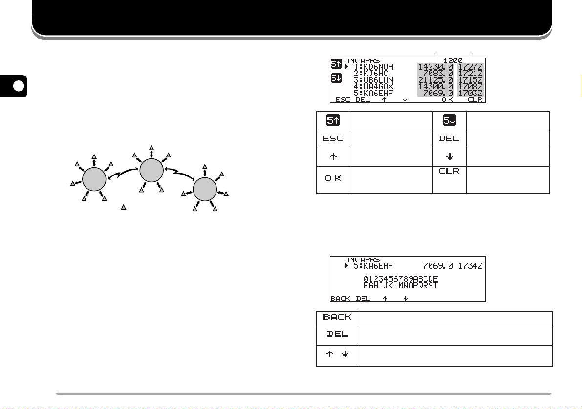
5 To read an attached comment, move the cursor (s)
cc
to the desired station using [
dd
c]/ [
d], then press
cc
dd
[OK].
• Up to 30 alphanumeric characters are displayed as a
comment.
Note: The information is cleared when the transceiver power is turned
OFF.

PACSATs
XR:BXT:A
BdnabdnastekcaptimsnartotAdnabsesU
,dnabXTatad=Adnab;stekcapeviecerot
.dnabXRatad=Bdnab
XT:BXR:A
BdnabdnastekcapeviecerotAdnabsesU
,dnabXRatad=Adnab;stekcaptimsnartot
.dnabXTatad=Bdnab
PACSATs refer to satellites designed and launched for
digital communications using the AX.25 protocol.
Several PACSATs are currently in orbit serving
thousands of hams throughout the world. The PACSATs
receive (uplink) on VHF and transmit (downlink) on UHF.
Some of them use FM to receive and SSB to transmit,
and operate at 1200 bps. The others use FM to both
receive and transmit, and operate at 9600 bps. This
transceiver allows communications with the 9600 bps
satellites. The PACSATs provide functions similar to
terrestrial PBBSs. You can use the satellites to send email, download a file, or enjoy other fascinating activities.
From the satellites equipped with high resolution
cameras, you may download still pictures taken in space.
In order to work the PACSATs, you need rotators that
allow azimuth and elevation control, plus high-gain
directional antennas. Your antenna has to track
satellites which travel from horizon to horizon. However,
many hams have been successfully using fixed
omnidirectional antennas. As for software, you need
dedicated programs capable of working the “broadcast”
protocols. Besides the “broadcast” programs, various
utilities which will ease your operations are available via
the Web pages of the Radio Amateur Satellite
Corporation (AMSAT); the world wide organization of
Amateur Satellite operators and supporters.
For further information, consult Internet Web pages
relating to the PACSATs. On one of the Internet search
engines, you may use “PACSAT” or “AMSAT” as a key
word to find those Web pages. It will also be wise to ask
help to one of your local satellite packeteers.
1 Access Menu 1–6–1 (DATA BAND) to select A:TX B:RX
(or A:RX B:TX).
3
2 Confirm that a VHF band has been recalled on the
data TX band.
3 T une the data TX band to the uplink frequency of the
target PACSAT.
4 Confirm that a UHF band has been recalled on the
data RX band.
5 T une the data RX band to the downlink frequency of
the PACSAT.
6 Press [F] (1 s), [TNC], then [F] (1 s), [TNC] again to
enter Packet mode.
•“TNC PKT” should appear.
For the subsequent steps, follow the manual for the
“broadcast” program and your reference material.
7

AUTOMATIC PACKET/ POSITION REPORTING SYSTEM
nocinoitatS
rotacolerauqsdirG/atadnoitisoP
tnemmocnoitisoPtxetsutatS
noitatsmorfecnatsiDnoitatsfonoitceriD
noitatseliboM
deepsgnivoM/noitceridgnivoM
noitatsdexiF
/annetnafothgieH/rewoptimsnarT
ytivitceridannetnA/niagannetnA
noitatsdexiF
desserpmocgnisu(
)tamrofatadSRPA
edutitlA/egnartimsnarT
noitatsrehtaeW
/deepsdniW/noitceriddniW
ruohtsalnillafniaR/erutarepmeT
The Automatic Packet/ Position Reporting System
(APRS) is a software program and registered
trademark of Bob Bruninga, WB4APR. He has made
packet communications much more exciting than before.
This program allows you to track mobile stations on a
map which you recall on a computer screen. Imagine
seeing one mobile station moving on the map which can
be scaled from .5 to 2000 miles. You also may be
tracked on the computer screen of another station.
4
Stations to be tracked must transmit beacons at certain
intervals. To track other stations, you usually need a
computer running the APRS, a transceiver, and a TNC.
To have them track you, you also need a GPS receiver.
It receives signals from the satellites to inform you of
your current geographical position. GPS stands for
Global Positioning System. The APRS interprets the
National Marine Electronics Association (NMEA) data
strings coming from the GPS receiver. For further
information, consult Internet Web pages relating to the
APRS. On one of the Internet search engines, you may
use “APRS” or “Packet Radio” as a key word to find
those Web pages.
8
This transceiver includes a TNC and a program for
dealing with data formats supported by the APRS. That
is, you need no other equipment to transmit, receive, or
display APRS packets. You do not need even a GPS
receiver if you enter position data manually to transmit.
For hams who want to fully enjoy APRS operations, this
transceiver has connection ports with a personal
computer and a GPS receiver. This manual, however,
does not describe APRS operations which require a
personal computer.
Using this transceiver, you can transmit a station icon,
position data, position comment, and status text. With a
GPS receiver, you can also transmit moving speed,
moving direction, and altitude data. From any type of
station you will receive information listed below:
Depending on the types of stations, you will also receive
the following information:

PACKET PATH AND DIGIPEATER
WIDE-type
RELAY-type
A packet path specifies how APRS packets should be
transferred via one or more repeaters. A repeater, which
is used for packet transfer, is commonly called a
digipeater. This came from a “digital repeater”. A
digipeater is usually located on a mountain top or high
building. Unlike a voice repeater, it operates on a
simplex frequency. Each volunteer who installs a
digipeater programs it either as a WIDE or RELAY type.
Generally a WIDE transmits packets over much greater
distances than a RELAY.
In any given area, there should be only one WIDE not to
cause extra traffic or collisions on frequencies. A WIDE
is capable of transferring packets from and to adjacent
WIDEs. Like a WIDE, there should be only one RELAY
in a given area; that area is usually much smaller than a
WIDE. So, transmit packets to a RELAY when you
cannot directly reach any WIDE. The RELAY then will
transfer the packets to any accessible WIDE.
On this transceiver, you can edit a packet path using a
maximum of 79 alphanumeric characters. The default is
“RELAY,WIDE” that is one of the common settings. With
this setting, packets will be transferred to a RELAY first,
then to a WIDE.
The APRS supports various methods for specifying a
packet path. Some of those methods are described on
page 24.
This transceiver with a built-in TNC may be used as a
digipeater. See page 27.
Note: To serve for mobile stations who always use the RELAY ,WIDE
path, most WIDEs also respond to packets addressed to a RELAY.
4
9
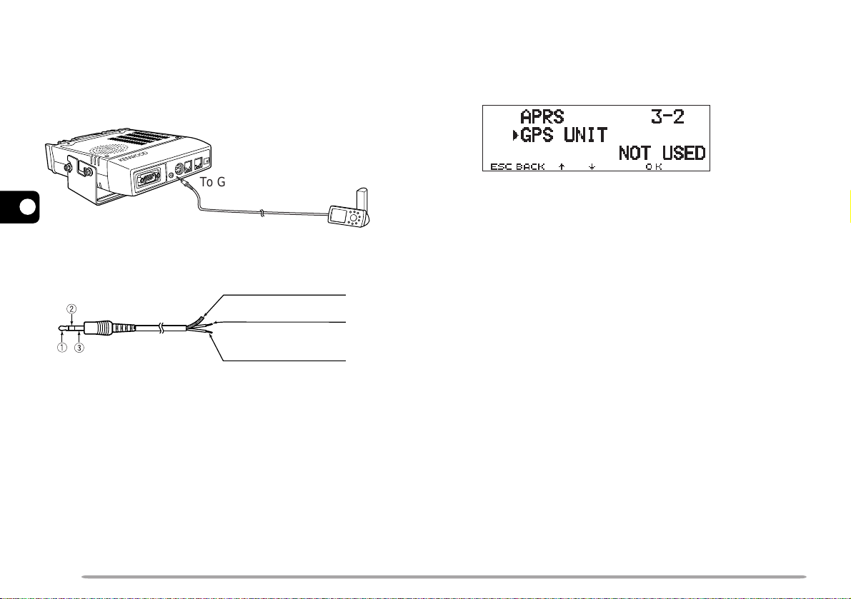
CONNECTING WITH A GPS RECEIVER
The GPS jack on this transceiver accepts a 2.5 mm (1/10")
3-conductor plug. If necessary, use the supplied cable to
modify the cable end of your GPS receiver .
To GPS jack
4
GPS receiver
e Shield
(to GND on GPS)
w Red
(to DATA OUT on GPS)
q White
(to DATA IN on GPS)
If using a GARMIN GPS receiver, select the following
parameters in the “INTERFACE” sub-menu on the
receiver.
• NMEA/NMEA
• NMEA 0183 2.0
• 4800 baud
In order to use the connected GPS receiver, access
Menu 3–2 (GPS UNIT) to select “NMEA” or “NMEA96”.
The default is “NOT USED”. Select “NMEA96” when
using a 9600 bps GPS receiver.
• When in APRS mode, “GPS” will appear on the restored
frequency display to indicate the setting of “NMEA” or
“NMEA96”. “GPS” blinks while measurement is being
executed.
Note: When using a GPS receiver with “AUTO” selected in Menu 3–C
(PACKET TX), this transceiver transmits an APRS packet for the first time
after any NMEA data is received.
10

OPERATION FLOW
The following flow chart includes only the steps to give
APRS a quick try.
y Access Menu 3–8 to select your station icon {page 18}.
u Access Menu 3–4 to program position data {page 19}.
q Access Menu 3–I to select band A or B as the data
band {page 13}. The default is band A.
w Press [F] (1 s), [TNC] to enter APRS mode.
•“TNC APRS” should appear.
e On the data band, select the same frequency as
other stations in your group.
• You may tune to the frequency of an appropriate
digipeater network (144.390 MHz in the U.S.) {page 9}.
Now you are ready to receive APRS packets from
other stations. Refer to “RECEIVING APRS DATA”
{page 14}. To transmit your APRS packet, proceed to
step r.
r Access Menu 3–1 to program your call sign
(9 digits max.) {page 17}.
t If you have connected a GPS receiver, access Menu
3–2 and select “NMEA” or “NMEA96” {page 10}.
The default is “NOT USED”.
i Access Menu 3–6 to select from 15 position
comments {page 20}.
o If you want, access Menu 3–9 to enter status text
using up to 28 alphanumeric characters {page 21}.
4
!0 Access Menu 3–C to select the operation method
for transmitting packets {page 25}.
!1 Press [F] (1 s), [BCON]. If you selected “PTT” in
step !0, then press and release Mic [PTT] {page 25}.
When using a personal computer, press [F] (1 s), [TNC],
then [F] (1 s), [TNC] again in step w to enter Packet
mode; “TNC PKT” should appear. All further operations
should be performed on your computer.
Menu Set-up allows you to change various default
settings for APRS operations. See the appropriate
sections in this chapter.
11
ADJUSTING THE INTERNAL CLOCK
This transceiver has a clock to manage information on
when APRS packets are received. Use Menu Set-up to
correct the current time, date, and if necessary the UTC
offset; UTC stands for Universal Time Coordinated.
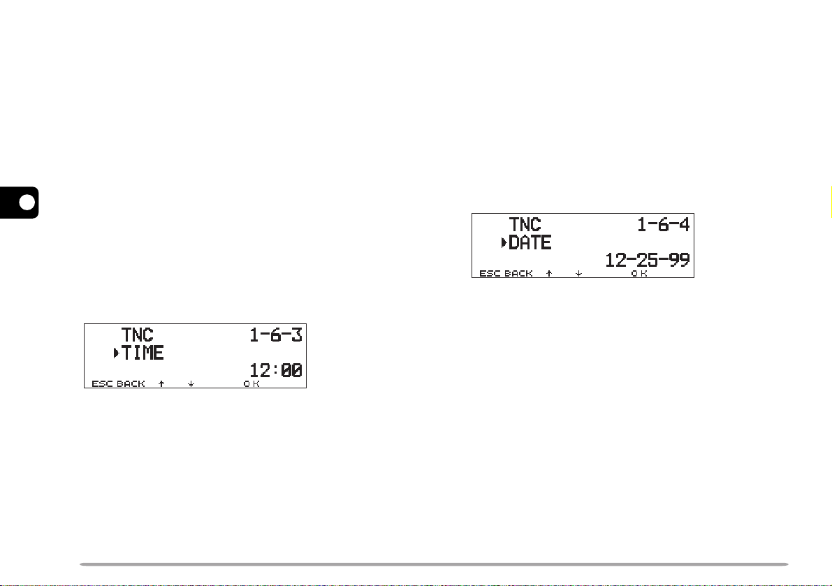
■ Setting Time
1 Press [MNU] to enter Menu mode.
cc
2 Press [
4
[OK].
3 Press [
[OK].
4 Press [
press [OK].
• The first 2 digits blink.
5 Press [
press [OK].
• To set 1 o'clock PM for example, select 13.
• The next 2 digits blink.
6 Press [
press [OK].
7 Press [MNU] to exit Menu mode.
12
dd
c]/ [
d] to select “RADIO (1–)”, then press
cc
dd
cc
dd
c]/ [
d] to select “TNC (1–6–)”, then press
cc
dd
cc
dd
c]/ [
d] to select Menu 1–6–3 (TIME), then
cc
dd
cc
dd
c]/ [
d] to enter the current hour, then
cc
dd
cc
dd
c]/ [
d] to enter the current minute, then
cc
dd
■ Setting Date
1 Press [MNU] to enter Menu mode.
cc
2 Press [
dd
c]/ [
d] to select “RADIO (1–)”, then press
cc
dd
[OK].
cc
3 Press [
dd
c]/ [
d] to select “TNC (1–6–)”, then press
cc
dd
[OK].
cc
4 Press [
dd
c]/ [
d] to select Menu 1–6–4 (DATE),
cc
dd
then press [OK].
• The first 2 digits blink.
cc
5 Press [
dd
c]/ [
d] to enter the current month (U.S.A./
cc
dd
Canada) or day, then press [OK].
• The next 2 digits blink.
cc
6 Press [
dd
c]/ [
d] to enter the current day (U.S.A./
cc
dd
Canada) or month, then press [OK].
• The last 2 digits blink.
cc
7 Press [
dd
c]/ [
d] to enter the current year, then
cc
dd
press [OK].
8 Press [MNU] to exit Menu mode.
Note:
◆
If you disconnect and reconnect the flexible cable between the radio
and TNC boards to replace the lithium battery, be sure to reset the
clock IC. Press [REV]+[LOW]+ POWER ON.
◆
When used at room temperature (25°C), the error of the internal
clock in a month is within one minute.
◆
The internal clock is effective until December 31, 2098.

■ Setting UTC Offset
1 Press [MNU] to enter Menu mode.
cc
2 Press [
dd
c]/ [
d] to select “RADIO (1–)”, then press
cc
dd
[OK].
cc
3 Press [
dd
c]/ [
d] to select “TNC (1–6–)”, then press
cc
dd
[OK].
4 Select Menu 1–6–5 (TIME ZONE), then press
[OK].
cc
5 Press [
dd
c]/ [
d] to select the appropriate UTC
cc
dd
offset, then press [OK].
• The selectable range is from +12:00 to –12:00 in
steps of 30 minutes.
6 Press [MNU] to exit Menu mode.
SELECTING DATA BAND
On this transceiver you can select data band for APRS
mode independent of the selection (in Menu 1–6–1) for
Packet mode. Access Menu 3–I (DATA BAND) and
select band A or B as the data band for receiving or
transmitting APRS packets. The default is band A. “ ”
indicates the current data band.
4
Note: In Menu 3–I, the selection switches among A, B, A:TX B:RX, and
A:RX B:TX. Select A:TX B:RX or A:RX B:TX if APRS networks which use
two separate frequencies become available in the future.
SELECTING PACKET TRANSFER RATE
The default APRS packet transfer rate set on the built-in
TNC is 1200 bps which is the standard among the
current APRS networks. If APRS networks which use
9600 bps transfer rate become available in the future,
access Menu 3–J (PACKET SPEED) and select “9600
bps”.
13

RECEIVING APRS DATA
rotacidnI gninaeM ?dedulcnIsitahW
Pd
noitisopetacilpuD
tnemmoc
ehtsatnemmocemaS
ehtmorfenosuoiverp
noitatsemas
Sd
sutatsetacilpuD
txet
ydaerlatxetsutatS
deviecer
P>
noitisopdnoyeB
timil
noitatsamorfataD
detcelesehtedistuo
}62egap{egnar
?Q
1
yreuQgnidnesroftseuqeR
noitamrofni
??
dedocedebtonnactahttekcaP
snoitceleS tekcaPweN
etacilpuD
tekcaP
tekcaPdilavnI
FFOpeeboNpeeboNpeeboN
ENIM
egasseMSRPArofylnodilavsinoitcelessihT
.}92egap{
WENLLApeeBpeeboNpeeboN
LLApeeBpeeBpeeB
Each time a new APRS packet is received, the frequency
display is interrupted to show information as below:
Position
comment
(or status text)
• The received APRS packet may include information on an
object such as a hurricane or tornado. In this case, the
4
name of the object appears instead of a call sign.
• Press [DETAIL] to access further information {page 15}.
• To restore the frequency display, press [ESC] or just wait
for approximately 10 seconds.
Note:
◆
When you receive an APRS packet including an “Emergency”
comment, a different format of display from the above will appear and
a different beep will sound.
◆
When you receive an APRS position packet that you transmitted, the
frequency display is not interrupted. “MY POS” will appear on the
display. This could happen when one or more digipeaters {page 9}
are used. If you receive a message {page 30} that you transmitted,
“MY MESSAGE” will appear.
If a received packet does not include new (or proper)
APRS data, the frequency display is not interrupted. An
indicator such as “dP” appears depending on the types
of data. See the table.
14
1
The transceiver automatically transmits the appropriate
information in approximately 2 minutes after receiving a
request.
Note: The APRS programs for PCs have entry fields for a position
comment and status text. The data entered to these two fields are
transmitted as separate packets. This transceiver, however, includes
both of a position comment and status text in one packet to transmit.
This transceiver beeps each time it receives any type of
APRS packet. You may access Menu 3–F (BEEP) to
change this setting. The default is “ALL”. The selection
in this menu is shared with APRS Message {page 29}.

ACCESSING RECEIVED APRS DATA
This transceiver is capable of receiving and storing
APRS data received from up to 40 stations in memory.
You can easily recall the information of the desired
station.
1 Press [F] (1 s), [LIST].
• The list of stations appears.
• The numbers beside the call signs indicate the order in
which data is received. The data received last is
assigned 1.
Situation
ehtfotsilehtsyalpsiD
2 Press [
cursor (s).
.snoitats5suoiverp
ehtserotseR
.yalpsidycneuqerf
.drawpu
cc
dd
c]/ [
d] to select the desired station using the
cc
dd
rosrucehtsevoM
yrtneegassemswollA
.}03egap{
noitatstnerrucehtot
DNABtfel(
)LES
.snoitats5txen
tnerrucehtseteleD
.noitats
rosrucehtsevoM
.drawnwod
3 Press [OK].
• The information of the selected station appears.
.snoitatsfotsilehtserotseR
.noitats
/
.}03egap{
.atad
• Depending on the types of stations, different types of
ehtfotsilehtsyalpsiD
.snoitatsllaseteleD
information will appear. For details, see the next page.
Note:
◆
When data from the 41st station is received, the oldest data in
memory is replaced by that data.
◆
Each time a new APRS packet is received from the same station, the
old data from that station (in memory) is replaced by new data.
When APRS data is received with a GPS receiver
tnerrucehtfonoitamrofnieritneehtseteleD
4
.snoitatsrehtoehtfonoitamrofniehtsyalpsiD
noitatstnerrucehtotyrtneegassemswollA
deviecerrofetaddnaemitneewtebsehctiwS
connected, included position data is sent to the receiver,
using the NMEA-0183 $GPWPL format (or Magellan
format). This data is registered in the W aypoint List of the
receiver. Access Menu 3–3 (WAYPOINT) and select the
number of characters to be input. Y ou can select 6 to 9
digits for NMEA, 6 digits for Magellan, DGPS, or OFF
(default) . With NMEA 6 digits selected, the right 6
characters of the call sign is used as a name (ex. for KJ6HC3, J6HC-3). Select DGPS to input differential position data to
a DGPS-compatible receiver if it is connected.
15

The information of the selected station is shown using up
to 5 lines on the display. The first three lines and the fifth
line show the same types of information while the fourth
line shows different types of information depending on
the types of stations.
r
1
For packets received from Mic-encoder stations
including TM-D700s and TH-D7s, position
4
comments are displayed in the fourth line.
Mobile station Fixed station
q
q Moving direction
w Moving speed
m: Mile/hour
k: km/hour
Weather station Object {page 14}
q
q Wind direction
w Wind speed
m: Mile/hour
k: km/hour
Mobile station
q
q Moving direction
w Moving speed
m: Mile/hour
k: km/hour
TM-D700 TH-D7/ Mic Encoder
q
Position comment
w Moving direction
q
t u
w
w
e Temperature
r
the past hour
(" or mm)
(compressed APRS data format)
w
e Altitude
e Moving speed
m: Mile/hour
k: km/hour
r Altitude
w
y
o
e r
Amount of rainfall in
e
' : Feet M: Meter
rewq
' : Feet M: Meter
e
q
Call sign (or object name)
w Time (packet received)
e Situation
r Station icon
t Position data
i
y Distance from station
(mile or km)
u Grid square locator
i Direction of station
o Position comment
(or status text)
q w e r
q Transmit power
w
Height of antenna
(elevation)
' : Feet M: Meter
q Moving direction
w Moving speed
m: Mile/hour
k: km/hour
Fixed station
q Transmit range
(mile or km)
q
Position comment
w Moving direction
(compressed APRS data format)
q w
e Antenna gain
r
Antenna directivity
omni :
Omnidirectional
e Call sign
w Altitude
' : Feet M: Meter
e Moving speed
m: Mile/hour
k: km/hour
16
This transceiver is capable of displaying the following 19
icons as station IDs. When icon data other than these is
received, the display will show an icon code such as /$ or \$.
Some icons may appear with overlay characters as below if
the received icon data includes them.
1
The following icons show the directions of stations relative
to your position. For example, “ ” indicates the other
station is located at the northeast relative to your position.
0.0 to 9999 miles (or km) are shown for distances from
ewq
other stations. “xxxxmi” (or “xxxxkm”) is shown for
distances over 9999 miles (or km). If you do not change
the position data in Menu 3–4 from the default, “----mi”
(or “----km”) is shown.
The default units for distance and temperature differ
depending on market versions; mile/ °F for the U.S.A./
Canada version, and kilometer/ °C for the other market
versions. If necessary, access Menu 3–G (MILE/
KILOMETER) and/or Menu 3–H (TEMPERATURE) to
change the setting(s).
ewq
Note: Some stations transmit APRS packets through TNCs connected to
GPS receivers. If you receive packets from those stations, “GOOD”
(satellites tracked) or ”LAST” (satellites not tracked) will be shown as the
situation, with GLL, GGA, or RMC which designates $GPGLL, $GPGGA,
or $GPRMC format.

PROGRAMMING A CALL SIGN
1 QZ1 7 PRS7
2 ABC2 8 TUV8
3 DEF3 9 WXY 9
4 GH I 4 0 0
5 JKL5 # –
6 MNO6
Program your call sign using a maximum of 9
alphanumeric characters. You may include SSID
characters in the string. Unless you program a call sign,
you cannot transmit APRS packets.
1 Press [MNU] to enter Menu mode.
cc
2 Press [
press [OK].
• The display for entering a call sign appears; the first digit
blinks. The default is “NOCALL”.
3 Turn the Tuning control to select the first digit.
• You can enter 0 to 9, A to Z, and –.
4 Press [
• The cursor moves to the next digit.
5 Repeat steps 3 and 4 to enter up to 9 digits.
dd
c]/ [
d] to select “MY CALLSIGN (3–1)”, then
cc
dd
aa
a].
aa
6 Press [OK] to complete the setting.
7 Press [MNU] to exit Menu mode.
The keypad on the MC-53DM also is available to enter
alphanumeric characters in step 3. Each press of a Mic
key switches entry of characters as below:
4
Note: To distinguish your various stations or nodes, you can have up to
15 Secondary Station IDentifiers (SSIDs); ex. WD6BQD-1 to WD6BQD-
15. You always have to put a dash between your call sign and SSID
number.
.ngisllac
DNABtfel(
.tigid
)LES
afoyrtneslecnaC
.gniknilb
rosrucehtsesuaC
.drawkcabevomot
tatigidehtseteleD
sirosrucehthcihw
yltnerrucehtstresnI
.retcarahcdetceles
tsrifehtotrosrucehtskcabdnastigidllasraelC
17

SELECTING YOUR STATION ICON
Select an icon which will be displayed on the monitors of
other stations as your ID. You may select an icon
depending on your current location.
1 Press [MNU] to enter Menu mode.
cc
2 Press [
press [OK].
4
3 Press [
“OTHERS”, then press [OK].
• The following 15 icons are selectable:
dd
c]/ [
d] to select “STATION ICON (3–8)”, then
cc
dd
cc
dd
c]/ [
d] to select from 15 icons plus
cc
dd
APRS supports approximately 200 icons. It allows users
to select each icon by specifying a combination of two
ASCII codes, for example, ! and /. One is a symbol
code, and the other is a table identification code (either /
or \). If you select “OTHERS” in step 3, use the following
procedures:
cc
4 Press [
dd
c]/ [
d] to select a symbol code, then press
cc
dd
[OK].
cc
5 Press [
dd
c]/ [
d] to select a table identification code,
cc
dd
then press [OK].
DOOWNEKtfarcriA
emoHtaoBkcurT
elbatroP
)tnet(
raCnaV
thcaYelcycrotoMreleehw81
VTSSpeeJretaepigiD
4 Press [MNU] to exit Menu mode.
18
noitaerceR
elcihev
• For icons that can include overlay characters, 0 ~ 9 and
A ~ Z are also selectable.
6 Press [MNU] to exit Menu mode.
Note: Because the icon code table is occasionally revised, download the
latest icon code table from Mr. Bruninga's W eb page (http://
web.usna.navy.mil/~bruninga/aprs.html). Click on “DOWNLOAD APRS”
on its home page, then download APRSnnn.zip from the FTP directory
where nnn is a 3-digit number. After uncompressing the zip file, you will
find a created README directory. Open and see Symbols.txt under this
directory.

PROGRAMMING POSITION DATA
This transceiver has 5 memory channels for storing
position data. Program latitude and longitude data for up
to 5 locations from which you will often transmit APRS
packets. You can also name the 5 memory channels.
Note: Grid squares were developed to shortly identify locations
anywhere on the Earth. The world is first divided into 324 areas (AA ~
RR) called “fields”. Each field is then divided into 100 “squares” (00 ~
99). Each square is further divided into 576 “sub-squares” (AA ~ XX).
The world is thus divided into 18,662,400 grids; each grid is expressed
with 6 digits.
1 Press [MNU] to enter Menu mode.
• You may press [F] (1 s), [POS] instead to skip step 2.
cc
2 Press [
press [OK].
3 Press [
press [OK].
• If you intend to use the current channel after exiting
Menu mode, press [USE] before pressing [OK]. An
asterisk appears at the left of the channel number.
• The display for entering a memory name appears; the
first digit blinks.
dd
c]/ [
d] to select “MY POSITION (3–4)”, then
cc
dd
cc
dd
c]/ [
d] to select from channels 1 to 5, then
cc
dd
Grid square
locator
4 Turn the Tuning control to select the first digit.
• You can enter alphanumeric characters plus special
ASCII characters.
5 Press [
• The cursor moves to the next digit.
aa
a].
aa
6 Repeat steps 4 and 5 to enter up to 8 digits, then
press [OK].
ciremunahplafostesehtgnomasehctiwS
,)ylnoE007D-MT(sretteldetnecca,sretcarahc
yromeMslecnaC
.yrtnEemaN
rosrucehtsesuaC
.drawkcabevomot
dnastigidllasraelC
otrosrucehtskcab
.tigidtsrifeht
7 Press [
.sretcarahcIICSAlaicepsdna
neewtebsehctiwS
.srettel
.gniknilb
cc
dd
c]/ [
d] to switch between north latitude
cc
dd
latipacdnallams
tatigidehtseteleD
sirosrucehthcihw
yltnerrucehtstresnI
.retcarahcdetceles
DNABtfel(
)LES
(default) and south latitude, then press [OK].
• The degree digits blink.
cc
8 Press [
dd
c]/ [
d] to select data for degrees, then press
cc
dd
[OK].
• The minute digits blink.
9 Repeat step 8 to select data for minutes (down to one
hundredth digit).
4
• To skip naming the channel, press [OK] again. You can
jump to step 7.
19

cc
)tluafed(ytuDffOetuoRnEecivreSnI
gninruteRdettimmoClaicepS
1
ytiroirP
1
!ycnegremE
2
6~0motsuC
10 Press [
dd
c]/ [
d] to switch between west longitude
cc
dd
(default) and east longitude, then press [OK].
• The degree digits blink.
cc
11 Press [
dd
c]/ [
d] to select data for degrees, then press
cc
dd
[OK].
• The minute digits blink.
12 Repeat step 11 to select data for minutes (down to
one hundredth digit).
4
SELECTING A POSITION COMMENT
The APRS data which you transmit always includes one
of the 15 predetermined position comments. Select an
appropriate comment depending on your situation.
1 Press [MNU] to enter Menu mode.
cc
2 Press [
then press [OK].
dd
c]/ [
d] to select “POSITION COMMENT (3–6)”,
cc
dd
13 As necessary, repeat steps 2 to 12 to store in up to 5
memory channels.
14 Press [MNU] to exit Menu mode.
The keypad on the MC-53DM also is available to enter
alphanumeric characters in step 4. See page ii.
To select and set from up to 5 programmed channels,
cc
repeat steps 1 to 3. In step 3 press [
dd
c]/ [
d] to select
cc
dd
the desired channel, then press [USE].
Note:
◆
If you have selected “NMEA” or “NMEA96” in Menu 3–2, pressing [F]
(1 s), [POS] does not allow you to access the display for entering
position data. The position data received via the GPS receiver most
lately will be displayed. Pressing [TIME SET] resets the internal
clock to the time input from the GPS receiver.
◆
If using a GPS receiver, you can also copy the measured data to the
position entry display for Menu 3–4. Press [F] (1 s), [POS] to display
the measured data, then press [COPY]. A message which asks the
channel number appears. Press [
number, then press [OK].
20
cc
dd
c
]/ [
d
] to select the channel
cc
dd
cc
3 Press [
dd
c]/ [
d] to select the desired comment.
cc
dd
4 Press [OK] to complete the setting.
• If you select “Emergency!”, a confirmation message
appears. Press [OK] again.
5 Press [MNU] to exit Menu mode.
The selectable comments are listed below:
1
Selecting these comments will highlight your station on all
other APRS computer displays.
2
Select this comment only when absolutely necessary. You
will activate alarms in all monitoring APRS stations.
Note: Custom 0 ~ 6 selectable in Menu 3–6 are not defined; these are
reserved for personal definition.

STORING STATUS TEXT
Status text is another comment to transmit with position
data. Unlike a position comment, you can make any
desired comment using a maximum of 28 alphanumeric
characters. This transceiver has 5 memory channels for
preprogramming.
Note: Attaching a long comment can double the size and length of the
packet. Transmit a comment only if necessary.
1 Press [MNU] to enter Menu mode.
cc
2 Press [
press [OK].
3 Press [
press [OK].
• If you intend to use the current channel after exiting
Menu mode, press [USE] before pressing [OK]. An
asterisk appears at the left of the channel number.
• The display for entering status text appears; the first
digit blinks.
dd
c]/ [
d] to select “STATUS TEXT (3–9)”, then
cc
dd
cc
dd
c]/ [
d] to select from channels 1 to 5, then
cc
dd
4 Turn the Tuning control to select the first digit.
• You can enter alphanumeric characters plus special
ASCII characters.
5 Press [
• The cursor moves to the next digit.
aa
a].
aa
6 Repeat steps 4 and 5 to enter up to 28 digits, then
press [OK].
ciremunahplafostesehtneewtebsehctiwS
.sretcarahcIICSAlaicepsdnasretcarahc
neewtebsehctiwS
.srettel
.gniknilb
latipacdnallams
tatigidehtseteleD
sirosrucehthcihw
yltnerrucehtstresnI
.retcarahcdetceles
)LES
.yrtnE
DNABtfel(
.tigidtsrifeht
7 As necessary, repeat steps 2 to 6 to store in up to 5
memory channels.
8 Press [MNU] to exit Menu mode.
The keypad on the MC-53DM also is available to enter
alphanumeric characters in step 4. See page ii.
To select and set from up to 5 programmed channels,
cc
repeat steps 1 to 3. In step 3 press [
dd
c]/ [
d] to select
cc
dd
the desired channel, then press [USE].
4
txeTsutatSslecnaC
rosrucehtsesuaC
.drawkcabevomot
dnastigidllasraelC
otrosrucehtskcab
21

PROGRAMMING A GROUP CODE
afoyrtneslecnaC
.edocpuorg
tatigidehtseteleD
sirosrucehthcihw
.gniknilb
rosrucehtsesuaC
.drawkcabevomot
yltnerrucehtstresnI
.retcarahcdetceles
DNABtfel(
)LES
tsrifehtotrosrucehtskcabdnastigidllasraelC
.tigid
Using a group code relieves you from receiving
unwanted packets. The APRS on this transceiver
supports the following three types of group codes.
All calls:
Program a 6-digit code that always starts with AP. You
will receive all APRS packets which include AP in group
codes. It does not matter whether or not the subsequent
4 digits match. The default on this transceiver is
APK101.
4
Note: APRS packets, which are generated via various methods, include
various codes instead of group codes. Using “All calls” allows you to
receive packets which include the following codes:
SPGMYSTSQQCNOCAEB
LLANRWYKSLIAMDILCPS
Special:
Enter “SPCL”. You will receive only APRS packets that
include SPCL as a group code. This code is generally
programmed by all stations at a special event.
Alternate net:
Program any other code with a maximum of 6 digits.
You will receive only APRS packets that include the
exact same code. In order to reject other packets, this
code should not include characters specified by the
above two types.
22
Note: Menu 3–E allows you to enter up to 9 digits (not just 6 digits)
because of possible future enhancement of the group code system.
1 Press [MNU] to enter Menu mode.
cc
2 Press [
dd
c]/ [
d] to select “UNPROTOCOL (3–E)”,
cc
dd
then press [OK].
• The display for entering a group code appears; the first
digit blinks. The default is APK101 (All calls).
3 Turn the Tuning control to select a character.
• You can enter 0 to 9, A to Z, and –.
4 Press [
• The cursor moves to the next digit.
aa
a].
aa
5 Repeat steps 3 and 4 to enter up to 9 digits.
6 Press [OK] to complete the setting.
7 Press [MNU] to exit Menu mode.
The keypad on the MC-53DM also is available to enter
alphanumeric characters in step 3. See page ii.

PROGRAMMING A PACKET PATH
1 QZ1 7 PRS7
2 ABC2 8 TUV8
3 DEF3 9 WXY 9
4 GH I 4 0 0
5 JKL5 # –,
6 MNO6
.ammocastresnIafoyrtneslecnaC
.htaptekcap
tatigidehtseteleD
sirosrucehthcihw
.gniknilb
rosrucehtsesuaC
.drawkcabevomot
yltnerrucehtstresnI
.retcarahcdetceles
DNABtfel(
)LES
dnastigidllasraelC
otrosrucehtskcab
.tigidtsrifeht
Program a packet path to specify how APRS data should
be transferred via one or more repeaters. For further
description, refer to “PACKET PATH AND DIGIPEATER”
{page 9}. The default is “RELAY,WIDE” that is one of the
common settings.
1 Press [MNU] to enter Menu mode.
cc
2 Press [
press [OK].
• The display for entering a packet path appears; the first
digit blinks.
3 Turn the Tuning control to select a character.
• You can enter 0 to 9, A to Z, , (comma), and –.
4 Press [
• The cursor moves to the next digit.
5 Repeat steps 3 and 4 to enter up to 79 digits.
• You can enter up to 8 path segments in sequence; each
segment must have less than 10 characters. Use a
comma to separate each segment.
dd
c]/ [
d] to select “PACKET PATH (3–B)”, then
cc
dd
aa
a].
aa
6 Press [OK] to complete the setting.
7 Press [MNU] to exit Menu mode.
The keypad on the MC-53DM also is available to enter
alphanumeric characters in step 3. Each press of a Mic
key switches entry of characters as below:
4
23

Let us describe five basic methods for editing a packet
retemaraP
forebmuN
sretaepigid
noitceriD
11 llA
22 llA
33 llA
44 llA
55 llA
66 llA
77 llA
8)eromro(2
1
htroN
9)eromro(2
1
htuoS
01)eromro(2
1
tsaE
11)eromro(2
1
tseW
21ynaM
2
htroN
31ynaM
2
htuoS
41ynaM
2
tsaE
51ynaM
2
tseW
path. Methods 3 to 5 are supported only by advanced
APRS networks.
Method 1 (Specific Path):
Program the call signs of one or more digipeaters in the
sequence of transfer relay; ex. “KD6ZZV,KF6RJZ”.
Method 2 (Generic Path):
Program RELAY and/or WIDE; ex. “RELAY,WIDE” (or
simply “R,W”). In this example, your APRS packet is
4
transferred to any RELAY digipeater near your position
first, then to any WIDE digipeater. You can also program
more than one WIDE. If you enter “WIDE,WIDE” for
example, your APRS packet will be transferred to any
WIDE near your position first, then to another WIDE.
Method 3 (WIDEN-N Path):
Program WIDEN-N, where both Ns indicate the number
of WIDE digipeaters to be used for relay. If you enter
“WIDE3-3” (or simply W3) for example, your APRS
packet will be relayed by three WIDEs in any direction.
Method 4 (TRACEN-N Path):
The operation is the same as WIDEN-N except that
digipeaters add their call signs to your packet before
forwarding. You may program “TRACE3-3” (or simply
T3) for example.
Method 5 (SSID Path):
Program a single number 1 to 15. You can easily specify
the number of digipeaters that will be used for relay. You
can also specify which directions of digipeaters relative
to your position will be used. See the table.
24
1
The first digipeater which receives your APRS data specifies
the entire route to the destination before forwarding; often 2
digipeaters are used in total.
2
The digipeater which receives your APRS data specifies the
call sign of the next digipeater before forwarding. This is
repeated until your APRS data reaches the destination.

SELECTING PACKET TRANSMIT METHOD
SELECTING PACKET TRANSMIT INTERVAL
Select the operation method for transmitting APRS
packets. The table concludes how operations differ
depending on the selection. Access Menu 3–C
(PACKET TX) and select Manual (default), PTT, or Auto.
LAUNAM
1 sserP )s1(]F[ , ]NOCB[ noitcnufehthctiwsot
•
2 ciMdlohdnasserP ]TTP[ ehtotnikaepsneht,
3 ciMesaeleR ]TTP[ .
TTP
OTUA
•
•
4 sserp,FFOnoitcnufehthctiwsoT )s1(]F[ ,
1 sserP )s1(]F[ , ]NOCB[ noitcnufehthctiwsot
•
•
2 sserp,FFOnoitcnufehthctiwsoT )s1(]F[ ,
fosserphcaE )s1(]F[ , ]NOCB[ ruoystimsnart
.tekcapSRPA
.NO
.sknilbdnasraeppa”NOCB“
.enohporcim
)LAVRETNIXT(D–3uneMnidetcelesemit
otgniknilbstrats”NOCB“litnutiaW.sessap
.ydaersignittimsnartetacidni
]NOCB[ .niaga
.NO
.sraeppa”NOCB“
SRPAruoystimsnartNOnoitcnufehtgnihctiwS
erastekcapSRPA,tahtretfA.ecnotekcap
.)LAVRETNIXT(D–3uneMnidetceles
]NOCB[ .niaga
You can change the interval for automatically
transmitting APRS packets. Access Menu 3–D (TX
INTERVAL) and select 0.2, 0.5, 1, 2, 3, 5, 10, 20, or 30
minutes. The default is 3 minutes.
Note:
◆
With “AUTO” in Menu 3–C and Beacon ON, pressing [OK] to
complete the setting causes the APRS packet to be immediately
transmitted. After that, APRS packets are transmitted at intervals of
the selected period.
◆
While signals are present, an APRS packet is not transmitted after
the interval. Approximately 2 seconds after signals drop, transmitting
is executed.
4
SELECTING STATUS TEXT TRANSMIT RATE
.tekcapSRPAruoystimsnarthctiwsehtgnisaeleR
ehtsselnutekcapSRPAnatimsnartertonnacuoY
doirepehtfoslavretnitadettimsnartyllacitamotua
A long status text string can double the size and length
of the APRS packet. Access Menu 3–A and specify how
frequently status text is included in APRS packets to be
transmitted. The selectable range is 1/1 to 1/8 and OFF
(default). If you select 1/3 for example, status text is
included in your packets once every 3 times; accordingly
stations who receive your packets will see your status
text once every 3 times.
25

RESTRICTING RECEPTION OF APRS DATA
FFO 1 2 3 4
83.05˚333.05˚33.05˚33.5˚33.˚33
08.31˚8118.31˚811.31˚811.1˚811.˚811
If APRS is popular in your area, you may receive too
many APRS packets for a short period. If this disturbs
your APRS activities, specify a distance from your
location. You will not receive APRS packets from
stations beyond this distance.
Access Menu 3–7 (POSITION LIMIT) and select the
range from 10 to 2500 in steps of 10, plus OFF (default).
The unit is mile or kilometer depending on the selection
in Menu 3–G (MILE/KILOMETER) {page 16}.
4
PACKET MONITOR DISPLAY
This transceiver presents Terminal Window mode to
display raw data of received APRS packets. It displays
up to 155 characters per page and holds up to 10 pages.
1 Press [F] (1 s), [P.MON] to enter Terminal Window
mode.
PROGRAMMING POSITION AMBIGUITY
There may be cases where you do not know or do not
want to report your precise locations. For position data,
you can select the number of digits not to be included in
your packets. Access Menu 3–5 (POS AMBIGUITY) and
select 1 to 4, or OFF (default). The table shows how the
digits are cleared.
26
2 To access old pages, press [HOLD].
cc
• Press [
• Press [RESUME] to quit the Hold function.
• While using the Hold function, newly received packets
will not be stored in buffer.
Note:
◆
The terminal window is not available for sending a command to the
TNC.
◆
The terminal window is available in APRS mode (not in Packet
mode).
◆
The data in buffer is cleared when the transceiver power is turned
OFF.
dd
c]/ [
d] to change the page.
cc
dd

SETTING AS A DIGIPEATER
1 QZ1 7 PRS7
2 ABC2 8 TUV8
3 DEF3 9 WXY 9
4 GH I 4 0 0
5 JKL5 # –,
6 MNO6
This transceiver with a built-in TNC may also be used as
a digipeater. As described in “PACKET PATH AND
DIGIPEATER” {page 9}, a volunteer who installs a
digipeater is supposed to program it either as a RELAY
or WIDE depending on various conditions.
Note: This transceiver is capable of setting up to 4 path segments
(aliases); each path segment must have less than 10 characters.
However, it is common to program either “RELAY” or “WIDE” as
mentioned above.
1 Press [MNU] to enter Menu mode.
cc
2 Press [
press [OK].
3 Press [
[OK].
4 Press [
[OK].
• The display for entering a path appears; the first digit
blinks.
dd
c]/ [
d] to select “DIGIPEATER (3–K)”, then
cc
dd
cc
dd
c]/ [
d] to switch the function ON, then press
cc
dd
cc
dd
c]/ [
d] to select “UIDIGI (3–L)”, then press
cc
dd
5 Turn the Tuning control to select a character.
• You can enter 0 to 9, A to Z, , (comma), and –.
6 Press [
• The cursor moves to the next digit.
aa
a].
aa
7 Repeat steps 5 and 6 to enter up to 39 digits.
.ammocastresnIafoyrtneslecnaC
tatigidehtseteleD
.gniknilb
sirosrucehthcihw
yltnerrucehtstresnI
.retcarahcdetceles
)LES
.htap
DNABtfel(
.tigidtsrifeht
8 Press [OK] to complete the setting.
9 Press [MNU] to exit Menu mode.
The keypad on the MC-53DM also is available to enter
alphanumeric characters in step 5. Each press of a Mic
key switches entry of characters as below:
rosrucehtsesuaC
.drawkcabevomot
4
dnastigidllasraelC
otrosrucehtskcab
27

APRS MESSAGE
The APRS supports a function for sending a message
or bulletin independent of position reports. You can send
a message to a single station only or a bulletin to all
other stations. You may use a group code to exchange
messages among members in your group or to reject
unwanted bulletins.
Each message which you transmit can consist of up to
64 alphanumeric characters. A maximum of 16 incoming
or outgoing messages can be held in the message
memory.
5
OPERATION FLOW
The following steps should guide you to a good start of
APRS Message operation.
q Access Menu 3–I to select band A or B as the data
band {page 13}. The default is band A.
w Press [F] (1 s), [TNC] to enter APRS mode.
•“TNC APRS” should appear.
e On the data band, select the same frequency as
other stations in your group.
• You may tune to the frequency of an appropriate
digipeater network (144.390 MHz in the U.S.) {page 9}.
r Access Menu 3–1 to program your call sign
(9 digits max.) {page 17}.
Now you are ready to receive a message from other
stations. Refer to “RECEIVING A MESSAGE” {page 29}.
To transmit a message, proceed to step t.
t Enter a message (or bulletin) using up to 64
alphanumeric characters {page 30}.
y If you want, access Menu 3–P (for messages) or
Menu 3–O (for bulletins) to program group codes
{page 34}.
u Access Menu 3–C to select the operation method
for transmitting {page 25}.
The method for transmitting differs depending on the
selection in Menu 3–C. See page 32.
When you send a message (not a bulletin), a reception
acknowledgment should be returned; “ack0 ~ 9 (or A ~ Z)”
appears. If your message is rejected by the recipient,
“rej0 ~ 9 (or A ~ Z)” appears.
Note: When using an optional VS-3 unit, you may select “APRS ONL Y”
in Menu 1–2–4 (VOICE). Each time you receive a message addressed
to you, the transceiver announces the call sign of the sender. If the initial
character of the message is %, the transceiver announces the
subsequent characters one by one.
28

RECEIVING A MESSAGE
snoitceleS tekcaPweN
etacilpuD
tekcaP
tekcaPdilavnI
FFOpeeboNpeeboNpeeboN
ENIM
egassemagniviecernehwylnospeeB
.uoyotdesserdda
WENLLApeeBpeeboNpeeboN
LLApeeBpeeBpeeB
Each time a proper message is received, the frequency
display is interrupted to show information as below:
Indicator
Message
When a duplicate message from the same station is
received, an error beep sounds; however, an
acknowledgment is returned. “dM” and a call sign
appear on the display.
• The display shows up to 64 characters of the message.
01” will appear to indicate the number of messages not
•“
yet read.
• The following indicators appear depending on the types of
received messages:
uoyotdesserddaegasseM
B
!
nitelluB
ecivreSrehtaeWlanoitaNehtybtropeR
egassem
To restore the frequency display after reading the
message, press [OK]. “ 01” will disappear. If you do
not read the message at this time, press [ESC]. “ 01”
will remain on the restored frequency display.
• The number increments if you press [ESC] for newly
received messages. Checking them with the List function
{page 31} causes the number to decrement. If “01” was
shown, both the number and message icon disappear.
• When a message to other stations is received, “oM”
appears.
This transceiver beeps each time it receives any type of
APRS packet. You may access Menu 3–F (BEEP) to
change this setting. The default is “ALL”.
ruoyot)noitcejerro(tnemgdelwonkcanoitpeceR
Note:
◆
This transceiver allows you to receive a message also when the
SSID does not match. However, it will not return a reception
acknowledgment.
◆
The dedicated memory is used for storing both incoming and
outgoing messages. Receiving a new message when the memory is
full causes the oldest message to be deleted. A message not yet
transmitted 5 times may be unexpectedly deleted. If the oldest
message has not been accessed using the List function when
memory is full, a new message does not replace the oldest message.
This transceiver will return a reject command and display “rM”.
5
29

ENTERING A MESSAGE
ciremunahplafostesehtneewtebsehctiwS
.sretcarahcIICSAlaicepsdnasretcarahc
neewtebsehctiwS
latipacdnallams
.srettel
egasseMslecnaC
.yrtnE)nitelluBro(
tatigidehtseteleD
sirosrucehthcihw
.gniknilb
rosrucehtsesuaC
.drawkcabevomot
yltnerrucehtstresnI
.retcarahcdetceles
DNABtfel(
)LES
dnastigidllasraelC
otrosrucehtskcab
.tigidtsrifeht
To transmit a message, first enter the call sign of the target
station. To transmit a bulletin, enter “BLN#” instead; where
# must be 0 to 9 or A to Z. When the length of your bulletin
exceeds 64 digits, you may transmit more than one packet
to send the entire bulletin. Use # to indicate the sequence
of the bulletin portions. For example, enter “BLN0” (or
“BLNA”) to send the first packet, then “BLN1” (or “BLNB”)
to send the second packet.
1 Press [F] (1 s), [MSG].
cc
2 Press [
• The display for entering a call sign appears; the first digit
5
blinks.
3 Turn the Tuning control to select the first digit.
• You can enter 0 to 9, A to Z, and –.
4 Press [
• The cursor moves to the next digit.
5 Repeat steps 3 and 4 to enter up to 9 digits.
)LES
30
dd
c]/ [
d] to select “INPUT”, then press [OK].
cc
dd
aa
a].
aa
.ngis
DNABtfel(
llacafoyrtneslecnaC
otrosrucehtsesuaC
.drawkcabevom
.gniknilb
6 Press [OK] to complete the setting.
• The display for entering a message appears; the first
digit blinks.
7 Turn the Tuning control to select the first digit.
• You can enter alphanumeric characters plus special
ASCII characters.
8 Press [
• The cursor moves to the next digit.
aa
a].
aa
9 Repeat steps 7 and 8 to enter up to 64 digits.
tatigidehtseteleD
sirosrucehthcihw
yltnerrucehtstresnI
.retcarahcdetceles
.tigidtsrifehtotrosrucehtskcabdnastigidllasraelC
10 Press [OK] to complete the setting.
The keypad on the MC-53DM also is available to enter
alphanumeric characters in steps 3 and 7. See page ii.

ACCESSING RECEIVED APRS MESSAGES
This transceiver is capable of storing a maximum of 16
messages in memory. You can easily access one of
those.
1 Press [F] (1 s), [MSG].
cc
2 Press [
dd
c]/ [
d] to select “LIST”, then press [OK].
cc
dd
If you select an incoming message, the following
display appears:
• The newer message the smaller number assigned; the
latest message is assigned 1.
tsiLegasseMstiuQ
rosrucehtsevoM
yrtneegassemswollA
noitatstnerrucehtot
DNABtfel(
)LES
.egassem
drawnwod
3 Press [
.yalpsiD
.drawpu
.}03egap{
cc
dd
c]/ [
d] to select the desired message using
cc
dd
the cursor (s).
4 Press [OK].
fotsilehtserotseR
.segassem
.egassem
.}03egap{
tnerrucehtseteleD
If you select one of your outgoing messages, the
suoiverpehtsyalpsiD
yrtneegassemswollA
noitatstnerrucehtot
DNABtfel(
)LES
.egassem
tnerrucehtseteleD
ehtsyalpsiD
.egassemtneuqesbus
tsetalehtsyalpsiD
ehtfoatadnoitisop
fi,noitatstnerruc
.yromemniderots
5
following display appears:
rosrucehtsevoM
tsetalehtsyalpsiD
ehtfoatadnoitisop
fi,noitatstnerruc
.yromemniderots
fotsilehtserotseR
.segassem
.egassem
.}03egap{
DNABtfel(
)LES
suoiverpehtsyalpsiD
yrtneegassemswollA
noitatstnerrucehtot
.egassem
tnerrucehtseteleD
ehtsyalpsiD
.egassemtneuqesbus
arofdesserpnehW
adengissaegassem
,}23egap{).(doirep
retnuocyrterehtsteser
.snoissimsnarterom5ot
.egassemtnerrucehtfosnoissimsnartrehtrufslecnaC
.}23egap{egassemehtotdengissasi).(doirepA
31

The table below shows the meanings of the symbols to
LAUNAM
ro
TTP
1 sserP )s1(]F[ , ]GSM[ .
2 sserP [c]/ [d] neht,”TIMSNART“tcelesot
sserp ]KO[ .
OTUA
gnisserP ]KO[ ruoystimsnart”OTUA“gnitcelesretfa
siti,tahtretfA.ecno)nitellubro(egassemSRPA
.etunimenofoslavretnitadettimsnartyllacitamotua
•staeperreviecsnarteht,deretneegassemahtiW
noitpeceralitnusemit5otpugnittimsnart
ti,nitellubaroF.denrutersitnemgdelwonkca
noitpecera;semit5gnittimsnarttaepersyawla
.denrutertonsitnemgdelwonkca
be shown in step 2.
q w e
Not-yet-read indicator
Time
(message received)
Sequence
q epyTegasseM
TRANSMITTING A MESSAGE
Select the operation method for transmitting APRS
messages (or bulletins). Access Menu 3–C (PACKET
TX) and select Manual (default), PTT, or Auto. This
selection is shared with the method for transmitting
position data {page 25}. The table concludes how
operations differ depending on the selection. For an
APRS message, there is no difference in the transmitting
methods between Manual and PTT selections.
5
uoyotdesserddaegasseM
BnitelluB
!ecivreSrehtaeWlanoitaNehtybtropeR
w ?XTroXR
–<)nitellubro(egassemdevieceR
1
>–
e sutatS
1
)n(
1
These indicators appear for outgoing messages (or bulletins).
1
1
.
32
.)nitellub
gnittimsnartrof)nitellubro(egassemA
forebmungniniamerehtsetacidni”n“
ro(egassemehtgnittimsnartrofsemit
noitpecerahcihwrofegassemA
denrutersawtnemgdelwonkca
5dettimsnart)nitellubro(egassemA
noitpecera,egassemaroF(semit
).denrutertonsawtnemgdelwonkca

AUTO ANSWER REPLY
1 qz1QZ 6 mno6MNO
2 abc2ABC 7 p r s7PRS
3 def3DEF 8 tuv8TUV
4 ghi4GHI 9 wxy9WXY
5 jkl5JKL 0
ecapS
0
#
?!' .,–/&#%()<>;:
"@
While you are driving, for example, you cannot
immediately answer to received messages. On this
transceiver, you can program the message to be
automatically returned when a message is received.
1 Press [MNU] to enter Menu mode.
cc
2 Press [
then press [OK].
3 Press [
4 Press [
press [OK].
• The display for entering a message appears; the first
digit blinks.
dd
c]/ [
d] to select “AUTO MSG REPLY (3–M)”,
cc
dd
cc
dd
c]/ [
d] to select “ON”, then press [OK].
cc
dd
cc
dd
c]/ [
d] to select “REPLY MSG (3–N)”, then
cc
dd
6 Press [
• The cursor moves to the next digit.
aa
a].
aa
7 Repeat steps 5 and 6 to enter up to 64 digits.
ciremunahplafostesehtneewtebsehctiwS
.sretcarahcIICSAlaicepsdnasretcarahc
neewtebsehctiwS
.srettel
.gniknilb
latipacdnallams
tatigidehtseteleD
sirosrucehthcihw
yltnerrucehtstresnI
.retcarahcdetceles
)LES
.yrtnE
DNABtfel(
egasseMslecnaC
rosrucehtsesuaC
.tigidtsrifeht
8 Press [OK] to complete the setting.
9 Press [MNU] to exit Menu mode.
The keypad on the MC-53DM also is available to enter
alphanumeric characters in step 5. Each press of a Mic
key switches entry of characters as below:
.drawkcabevomot
dnastigidllasraelC
otrosrucehtskcab
5
5 Turn the Tuning control to select the first digit.
• You can enter alphanumeric characters plus special
ASCII characters.
33

PROGRAMMING A GROUP CODE
Use a message group code to exchange messages only
among your group members. With one or more
message group codes programmed, you will receive
messages that include the same group code(s), besides
messages addressed to you. If you program one or
more bulletin group codes, you will not receive bulletins
addressed to other specific groups. You can program
any desired code using alphanumeric characters; up to 9
characters for messages, and up to 4 characters for
bulletins. You can also program up to 6 codes at the
same time; each code must be separated by a comma
(,). If you program 3 message group codes, for example,
5
you will receive all messages that include one of the 3
codes. If you program 3 bulletin group codes, you will
reject bulletins addressed to specific groups which do
not use any of the 3 codes.
1 Press [MNU] to enter Menu mode.
cc
2 Press [
“BLN GROUP (3–O)”, then press [OK].
• The display for entering one or more group codes
appears; the first digit blinks.
dd
c]/ [
d] to select “MSG GROUP (3–P)” or
cc
dd
4 Press [
• The cursor moves to the next digit.
aa
a].
aa
5 Repeat steps 3 and 4 to enter up to 6 codes.
.ammocastresnIafoyrtneslecnaC
tatigidehtseteleD
.gniknilb
sirosrucehthcihw
yltnerrucehtstresnI
.retcarahcdetceles
DNABtfel(
)LES
.edocpuorg
rosrucehtsesuaC
.drawkcabevomot
otrosrucehtskcab
.tigidtsrifeht
6 Press [OK] to complete the setting.
7 Press [MNU] to exit Menu mode.
The keypad on the MC-53DM also is available to enter
alphanumeric characters in step 3. See page ii.
In order to include a message group code in your
outgoing packet, enter a group code in place of a call
sign {page 30}. To include a bulletin group code, enter it
following BLN# {page 30}; for example, “BLN#ABC”
where ABC is a group code. Use up to 9 characters for
a message group code or up to 4 characters for a
bulletin group code.
Note: Unlike a message, a bulletin including a group code will be
received by stations who do not program any bulletin group code.
dnastigidllasraelC
3 Turn the Tuning control to select the first digit.
• You can enter 0 to 9, A to Z, , (comma), and –. For
messages, “
” is also selectable.
34

Slow-scan Television (SSTV) is a popular application for
1 NC
2 SSDO
3 6V
4 DG
5 TXD
6 RXD
7 SSPTT
8 FSSDO
9 SSDI
10 NC
11 PTT
12 3MS
13 SP
14 MIC
15 MSP
16 G
1
2
3
4
5
6
7
8
9
On TM-D700
DATA connector
On VC-H1
DATA port
COM connector
transmitting still images over the air from one station to
another. The VC-H1 is an optional portable unit which
includes all requirements for SSTV; a slow-scan
converter, a CCD camera, and an LCD monitor. You can
transmit or receive full-color images just by connecting
the VC-H1 to this transceiver. For further information on
the VC-H1, see the instruction manual for the VC-H1.
From this transceiver you can enter and superimpose a
message, an RSV report, and a call sign onto an image
on the VC-H1 monitor. You can also select colors for
those information.
SLOW-SCAN TELEVISION (SSTV) WITH VC-H1
CONNECTION WITH VC-H1
In order to use the full functions supported by this
transceiver, you need to prepare two cables by yourself.
You may use a commercially available female DB-9
connector, an optional PG-5A cable equipped with a 6pin mini DIN plug, and an optional connector kit (E590407-XX) which mates with the VC-H1 DATA port; one
end of the PG-5A cable has not been connectorized.
Note:
◆
◆
◆
Switch OFF both the transceiver and VC-H1 before making the
connection.
An optional PG-4T cable mates with both the DATA connector on this
transceiver and the DATA port on the VC-H1. This cable alone,
however, allows only image transfer from/ to other stations.
The VC-H1 functions as a speaker microphone only when connected
with a handy transceiver.
6
35

ENTERING CALL SIGN/ MESSAGE/ RSV
ytilibadaeR oediV
1elbadaernU1elbazingocernU
2elbadaeryleraB2elbazingoceryleraB
3
elbaredisnochtiwelbadaeR
ytluciffid
3
htiwelbazingoceR
ytluciffidelbaredisnoc
4
onyllacitcarphtiwelbadaeR
ytluciffid
4
htiwelbazingoceR
ytluciffidonyllacitcarp
5elbadaeryltcefreP5elbazingoceryltcefreP
htgnertSlangiS
1elbitpecrepylerabslangistniaF6slangisdooG
2slangiskaewyreV7
gnortsyletaredoM
slangis
3slangiskaeW8slangisgnortS
4slangisriaF9slangisgnortsylemertxE
5slangisdoogylriaF
Use the following procedures to enter a call sign, a
message, or an RSV report. RSV stands for readability,
signal strength, and video. If you receive a clear image
free from noise, the RSV report should be 595.
Note: The only difference among Menus 2–1, 2–3, and 2–5 is the
maximum number of digits that you can enter. So you may enter another
message using Menu 2–5, for example.
1 Press [MNU] to enter Menu mode.
cc
2 Press [
“MESSAGE (2–3)”, or “RSV (2–5)”, then press [OK].
• The display for entering characters appears; the first
digit blinks.
6
3 Turn the Tuning control to select a character.
• You can enter 0 to 9, A to Z, –, /, !, and ?.
4 Press [
• The cursor moves to the next digit.
5 Repeat steps 3 and 4 to enter up to 8 digits (call
sign), 9 digits (message), or 10 digits (RSV report).
36
dd
c]/ [
d] to select “MY CALL (2–1)”,
cc
dd
aa
a].
aa
,ngiSllaCslecnaC
.yrtnE
DNABtfel(
.tigid
)LES
VSRro,egasseM
.gniknilb
rosrucehtsesuaC
.drawkcabevomot
6 Press [OK] to complete the setting.
7 Press [MNU] to exit Menu mode.
The keypad on the MC-53DM also is available to enter
alphanumeric characters in step 3. See page ii.
tatigidehtseteleD
sirosrucehthcihw
yltnerrucehtstresnI
.retcarahcdetceles
tsrifehtotrosrucehtskcabdnastigidllasraelC

SELECTING COLOR FOR CALL SIGN/ MESSAGE/ RSV
EXECUTING SUPERIMPOSITION
You can select white (default), black, blue, red, magenta,
green, cyan, or yellow to color the call sign, message, or
RSV report.
1 Press [MNU] to enter Menu mode.
cc
2 Press [
“MESSAGE COLOR (2–4)”, or “RSV COLOR (2–6)”,
then press [OK].
3 Press [
4 Press [OK] to complete the setting.
5 Press [MNU] to exit Menu mode.
dd
c]/ [
d] to select “MY CALL COLOR (2–2)”,
cc
dd
cc
dd
c]/ [
d] to select the color.
cc
dd
After connecting the VC-H1 to this transceiver, use the
following procedure to execute superimposition. First
recall the desired image on the VC-H1.
1 Press [MNU] to enter Menu mode.
cc
2 Press [
then press [OK]
• “EXECUTING” appears and data transfer starts.
3 Press [MNU] to exit Menu mode.
Note: Switch OFF both the transceiver and VC-H1 before making the
connection.
dd
c]/ [
d] to select “2–7 (SUPERIMPOSE)”,
cc
dd
6
37

SSTV MODE CHANGE
dna007D-MT
lortnocetomer
ehtsiycneuqerftnerrucehT
.noitatstegratehtsaemas
dna007D-MT
lortnocetomer
hctamseicneuqerfenotehT
1
.
lortnocetomeR.NOsinoitcnufenoTehT
1H-CVNOsirewopehT
2
.
You can also change the SSTV mode set on the VC-H1,
from this transceiver. First connect the transceiver to the
VC-H1, and switch ON both the transceiver and VC-H1.
The selectable SSTV modes are as follows:
63)roloc(toboR27)roloc(toboR09TVA
49TVA1SeittocS2SeittocS
1MnitraM2MnitraMMFtsaF
1 Press [MNU] to enter Menu mode.
cc
2 Press [
dd
c]/ [
d] to select Menu 2–8 (TX MODE), then
cc
dd
press [OK].
• The SSTV mode currently set on the VC-H1 appears.
cc
3 Press [
6
dd
c]/ [
d] to select the desired mode.
cc
dd
4 Press [OK] to change the setting.
5 Press [MNU] to exit Menu mode.
Note: When using Fast FM, switch OFF the Tone, CTCSS, or DCS
function.
VC-H1 CONTROL
If you have another transceiver that has the Tone
function, you can use it as a remote control for the
VC-H1. Transmit a subaudible tone from the remote
control to this transceiver connected with the VC-H1 for
more than 1 second. Then this transceiver causes the
VC-H1 to capture an image, executes the
superimposition, and transmits the image to the target
station. You must select the same tone frequency on
both transceivers; on this transceiver, program a CTCSS
frequency; see page 55 on the other manual (main).
38
Access Menu select 2–9 (VC SHUTTER) and select
“ON”.
• Switching the function ON activates the CTCSS; “CT”
appears.
The following table concludes the settings you must confirm:
1
For the TM-D700, program a matching CTCSS frequency.
2
The camera and LCD monitor must not be left ON.
Note:
◆
If you have made no entry for superimposition, superimposition will
not be executed.
◆
“EXECUTING” appears and blinks on this transceiver while a series
of operations is in progress.
◆
In order to use this function, select a SSTV mode other than Fast FM.

TROUBLESHOOTING
The problems described in this table are commonly encountered operational malfunctions and are usually not caused
by circuit malfunctions. For the reference pages in parentheses, see the other instruction manual (main).
melborP esuaCelbaborP noitcAevitcerroC egaP.feR
stlusernoitarepotekcaP
1 .neposihcleuqsehT 1 tahtoslevelhcleuqstcerrocehttceleS
htiwstcennoconni
.snoitatsrehto
2 emasehttcelestondiduoY
ynaeviecertondiduoY
.atadretsulcXD
timsnarttonnacuoY
1 .FFOsinocaeB 1 sserP )s1(]F[ , ]NOCB[ hctiwsot
.atadSRPAyna
2 .neposihcleuqsehT 2 tahtoslevelhcleuqstcerrocehttceleS
3 .evitcanisidnabatadehT 3 ,dnabatadehtdeknalbevahuoyfI
4 .edomSRPAtcelestondiduoY 4 sserP )s1(]F[ , ]CNT[ SRPAretneot
5 .edomtekcaPdetcelesuoY 5 sserP )s1(]F[ , ,]CNT[ neht )s1(]F[ ,
6 ruoymargorpyltcerroctondiduoY
.ngisllac
2 ehttcelesotdnammocDUABHesU
.noitatstegratehtsaetarrefsnart
.edomSRPAehttcelestondiduoYsserP )s1(]F[ , ]CNT[ SRPAretneot
“;edom SRPACNT .raeppadluohs”
.NOnocaeB
)s1( .tievitcaot
“;edom SRPACNT .raeppadluohs”
]CNT[ “;niaga SRPACNT dluohs”
.raeppa
6 margorpyltcerrocot1–3uneMesU
.tneserperaslangis
.etarrefsnartetairporppa
.tneserperaslangis
etairporppaehtsserp ]LESDNAB[
.ngisllacruoy
nehwylnodeneposihcleuqseht
nehwylnodeneposihcleuqseht
)02(
4
6
52
)02(
)66(
11
11
71
7
39

melborP esuaCelbaborP noitcAevitcerroC egaP.feR
ynaeviecertondiduoY
1 amargorpyltcerroctondiduoY
.tekcapSRPA
2 atadehttesyltcerroctondiduoY
3 etairporppaehttcelestondiduoY
SPGagnisunehW
”OTUA“htiwreviecer
C–3uneMnidetceles
diduoy,)XTTEKCAP(
ynatimsnartton
.atadnoitisop
7
tonnacuoY
esopmirepus
ehtotnonoitamrofni
.rotinom1H-CV
margorptonnacuoY
VTSSahtiw1H-CVeht
.edom
etavitcatonnacuoY
etomeR,nacSlausiV
,)3–A–1uneM(lortnoC
–1uneM(retaepeRron
.)6–7
.edocpuorg
.tibytirapdnahtgnel
.etarrefsnarttekcap
.tnemerusaemtcerroc
retneyltcerrocotdeliafuoY
.desopmirepusebotnoitamrofni
.snoitcennocelbacdaB ehtroflaunamnoitcurtsniehtotrefeR
1 margorpdnaE–3uneMsseccA
.”101KPA“
2 ehtdnes,edomtekcaPtceleS
8WA ]RETNE[ 0RAP, ]RETNE[ neht,
TRATSER ]RETNE[
3 ehttcelesotJ–3uneMesU
tratsteytondidreviecerSPGehT
.edomtekcaProSRPAdetcelesuoYsserP ]F[)s1( , ]CNT[ osyldetaeper
“rehtien SRPACNT “ron” TKPCNT si”
.elbisiv
22
84,74,14
neht,CNTehtotsdnammocgniwollof
:edomSRPAtceles
31
etarrefsnarttekcapetairporppa
.)spb0021yllareneg(
reviecsnarteht,detceles”OTUA“htiW
redroniatadAEMNynaeviecertsriftsum
tonfI(.atadnoitisopruoytimsnartot
2–3uneMssecca,reviecerSPGagnisu
.)”DESUTON“tcelesdna
retneyltcerrocot6–2ot1–2uneMesU
.noitamrofniderisedeht
1H-CVehttcennocyltcerrocdna1H-CV
.reviecsnartehtot
01
73,63
53
11,4
40

APPENDIX
TNC COMMANDS LIST
The commands supported by the built-in TNC are listed below. You must enter a space between a command name (or
short-form) and a parameter, or between two parameters; ex. AU OFF, BEACON EVERY 18.
emaNdnammoC trohS tluafeD retemaraP noitpircseD
VNOCTIB88NOFFO/NO
RETLIFAFA00$08$~00$
FLOTUAUANOFFO/NO
YALEDXADXA0 021~0
GNAHXAHXA0 052~0
/YREVE
NOCAEBB0YREVE
TXETBTB—
TARBILACLAC— —
nRETFA
)052~0=n(
951~0
sretcarahc
.edomesrevnoCninehwstekcap
.)RC(nruteregairrac
.sdnocesillim01si
.sdnocesillim001siretemarap
.sdnoces01
esrevnoCnistib8gnisuretcarahcenoseldnah,NOnehW
.stib7gnisuretcarahcenoseldnah,FFOnehW.edom
deviecermorfdevomerebotsedoclortnoc4otpuseificepS
hcaeretfaretupmocehtot)FL(deefenilasdnes,NOnehW
neewtebYALEDXTotdeddaebotemityaledehtseificepS
retemarapehtfotinuehT.noissimsnartfotratsdnaNOTTP
ehtfotinuehT.emitgnahretaepereciovehtseificepS
ehtfoslavretnitatekcapnocaebasdnes,YREVEottesfI
tekcapnocaebasdnes,RETFAottesfI.)n(doirepdeificeps
sinfotinuehT.)n(doirepdeificepsehtretfaecnoylno
.tekcapnocaebafonoitropatadehtfotnetnocehtseificepS
otQretnE.)oitar05/05(evawerauqskram/ecapsasdneS
.edomdnammoCehterotserdnaedometarbilaCtixe
41

emaNdnammoC trohS tluafeD retemaraP noitpircseD
KCEHCHC03052~0
EDOMNOCMNOCC T/C
TCENNOCC—
)9llac
KONOCONOCNOFFO/NO
PMATSNOCSNOCFFOFFO/NO
ESREVNOC
EMITCAPCPCFFOFFO/NO
RCRCNOFFO/NO
PMATSYADSYADFFOFFO/NO
EMITYADAD— —
ASUYADUYADNOFFO/NO
TAEPIGIDGIDNOFFO/NO.retaepigidasanoitcnufotCNTehtswolla,NOnehW
VNOC
Kro
——
AIV(1llaC
...,3llac,2llac
retne C roesrevno T sinoitcennocnehwedomtnerapsnar
.detelpmoc
.tekcapMD
.tnes
fonoitucexelitnutuo-pordlangismorflavretniehtseificepS
.sdnoces01siretemarapehtfotinuehT.noitcennocsid
yllacitamotuaotCNTehtsesuac,FFOottesEDOMONhtiW
noitatsehtfongisllacehtsi1llaC.tseuqertcennocasdneS
otsnoitatsfosngisllacera9llacot2llaC.otdetcennocebot
.hguorhtdetaepigideb
AUasnruterdnatseuqertcennocastpecca,NOnehW
asnruterdnatseuqertcennocastcejer,FFOnehW.tekcap
nehwemitdnaetadtnerrucehtsyalpsid,NOnehW
ebtsumemitdnaetadtcerrocehT.detelpmocsinoitcennoc
.EMITYADgnisutes
sserP.edomesrevnoCretneotCNTehtsesuaC ]C[+]lrtC[ ot
.edomdnammoCehterotser
slavretnitatekcapasdnes,edomesrevnoCnidnaNOnehW
.EMITCAPybdenimreteddoirepehtfo
ebotstekcapllaot)RC(nruteregairracasdneppa,NOnehW
gnisserp,NOnehW ]T[+]lrtC[ ehtsesuacedomesrevnoCni
.atademitotnoitiddaniatadetaddnesotCNT
.ssmmhhDDMMYYretnE.emitdnaetadtnerrucehtsteS
.dettimosidnocesehtfoyrtnefidnocesehtsa00steS
,FFOnehW.YY/DD/MMekiletadehtsyalpsid,NOnehW
.YY-MM-DDekiletadehtsyalpsid
42
ENNOCSIDD—— .tseuqertcennocsidasdneS

emaNdnammoC trohS tluafeD retemaraP noitpircseD
YALPSIDPSID— —
TIAWDWD03052~0
OHCEENOFFO/NO
.retupmoc
HTAPEHTAPE— 7llac...,1llaC
RLCTXECTXE— — .xobliamCNTehtfostnetnocehtsraelC
ELIFIF— — .xobliamCNTehtnisegassemllafotsilehtsyalpsiD
RNRMRIFRIFFFOFFO/NO
.eciton”ydaer“
REVOLFLF0 021~0
.etunim1si
WOLFFNOFFO/NO
ehtllafosutatstnerrucehtyalpsidotCNTehtsesuaC
,I,H,C,AreifitnedissalcayficepsoslanacuoY.sdnammoc
dnammocderisedehtylnofosutatsehtyalpsidotTro,M,L
adnaemandnammocehtneewtebecapsaretnE.ssalc
.HYALPSID.xe;reifitnedissalc
sretemaraptropC232-SR:)CNYSA(A
sretcarahcCNTlaicepS:)RAHC(C
sretemarapretnuoC:)HTLAEH(H
sretemarapDI:)DI(I
sutatsknilCNT-ot-CNT:)KNIL(L
sretemaraprotinoM:)ROTINOM(M
sretemarapgnimiT:)GNIMIT(T
noitucexelitnunoitcetedreirraconmorflavretniehtseificepS
.sdnocesillim01siretemarapehtfotinuehT.noissimsnartfo
ehtotsretcarahcdeviecerohceotCNTehtsesuac,NOnehW
DISSIUehtnehwdeddaebotsngisllacretaepigidseificepS
.41ro01sitekcapdevieceraniretemarap
tonsitifiuoyot)tekcap(ecitonasdnesnoitatsrehtoehT
ecitonahcusgniviecer,NOnehW.atadeviecerotydaer
aseviecertilitnunoissimsnartdnepsusotCNTehtsesuac
semocebreffubCNTehtnehwmorfyadedemitehtseificepS
retemarapehtfotinuehT.deraelcsireffubCNTehtlitnulluf
potsotretupmocehtsesuacyrtneyekgnitrats,NOnehW
.stekcapdeviecergniyalpsid
43

emaNdnammoC trohS tluafeD retemaraP noitpircseD
KCARFRF3 51~0
PUDLLUFUFFFOFFO/NO
DUABGBG00840069/0084
DNESSPGSSPG—
TXETSPGTSPGSTNP$
DUABHBH00210069/0021
DELLAEHLAEHFFOFFO/NO
DIHIHNOFFO/NO
DII—— .tekcapDInadnesotCNTehtsesuaC
LLIKIK— —
951~0
sretcarahc
6~0
sretcarahc
foyrterlitnunoissimsnartenomorflavretniehtseificepS
.dnoces1siretemarapehtfotinuehT.noissimsnart
nehW.xelpudllufninoitcnufotCNTehtswolla,NOnehW
diovaotslangistcetedreirracatadesuottiswolla,FFO
.noisilloctekcap
ehtneewtebetarrefsnartehtsaspb0069ro0084stceleS
.reviecerSPGehtdnaCNT
;reviecerSPGehtottuptuoebotatadfotnetnocehtseificepS
ehtnosgnittestluafedehtmargorpotdesusiatadsiht
.yromemniderotstonsiatadtuptuoehT.reviecer
.TXETLybdenimretedebotegassemafoepytehtseificepS
tekcapneewtebetarrefsnartehtsaspb0069ro0021stceleS
.snoitats
eraMORehtfosnoitarepolamrontonrorehtehwsenimreteD
,detcetederasnoitarepolamronfidnaNOnehW.dekcehc
.yletanretlaknilbdnaraeppa”NOC“dna”ATS“
5.9yrevetekcapDInadnesotCNTehtsesuac,NOnehW
.gnitaepigidretfasetunim
otnIKretnE.xobliamCNTehtnisegassemcificepsseteleD
.rebmunegassemasinerehwegassemcificepsenoeteled
.egassemcificepsenonahterometeledot.....n,n,nIKretnE
tsaelehtevahhcihwsegassem01eteledot%IKretnE
ehtevahhcihwsegassem01eteledot&IKretnE.srebmun
.srebmuntsegral
44

emaNdnammoC trohS tluafeD retemaraP noitpircseD
SSIKSSIKFFOFFO/NO
MAERTSCLSCLNOFFO/NO
TSILIL— —
/YREVE
NOITACOLCOL0YREVE
GOLGOL— —
HTAPLAPLSPG
TXETLTL—
NOMTLMTL0 052~0
LIAMIAMFFOFFO/NO
LLAMAMNOFFO/NO
nRETFA
)052~0=n(
.xobliam
AIV(1llaC
...,3llac,2llac
)9llac
951~0
sretcarahc
.atad
CNTehtsesuacNOnehtFFOrewopehtgnihctiws,NOnehW
dnaraeppa”NOC“dna”ATS“.edomSSIK)tixero(retneot
SSIKsretneCNTehtnehwsemitlarevesyletanretlaknilb
FF0Cyranibehtdnesyamuoy,edomSSIKtixeoT.edom
.draobyekruoymorf)sretcarahcIICSAton(dnammoc0C
asaderetne)zhguorhta(rettelllamsasegnahc,NOnehW
maertsA.)ZhguorhtA(rettellaitipacaot,rotangisedmaerts
.WSMAERTSretfayletaidemmideretneebtsumrotangised
nahtrehto,xobliamCNTehtni,segassemfotsilehtsyalpsiD
.snoitatsrehtootdesserddaesoht
deificepsehtfoslavretnitaatadSPGsdnes,YREVEottesfI
retfaecnoylnoatadSPGsdnes,RETFAottesfI.)n(doirep
.sdnoces01sinfotinuehT.)n(doirepdeificepseht
CNTehtotdetcennocevahhcihwsnoitatsfotsilehtsyalpsiD
fongisllacehtsi1llaC.atadSPGdnesotsngisllacseificepS
ebotsnoitatsfosngisllacera9llacot2llaC.noitanitsedeht
.hguorhtdetaepigid
SPGnidedulcniebotegassemafotnetnocehtseificepS
ybdenimretedegassemagniyalpsidroflavretniehtseificepS
devieceraekilsraeppaegassema;neercsehtnoTXETL
.dnoces1siretemarapehtfotinuehT.tekcapnocaeb
desserddaegassemasdlohxobliamCNTehtdnaNOnehW
.lanimretDELLIAMehtot”woL“stuptuo,uoyot
rehtoneewtebderrefsnartstekcapllasrotinom,NOnehW
.stekcapdetcennocnuylnosrotinom,FFOnehW.snoitats
45

emaNdnammoC trohS tluafeD retemaraP noitpircseD
46
EMARFXAMXAM4 7~1
DOBMBMFFOFFO/NO.desuebotxobliamCNTehtswolla,NOnehW
MOCMMOCMFFOFFO/NO
NOCMCMFFOFFO/NO
ENIMIM— —
ROTINOMMNOFFO/NO.stekcaprotinomotCNTehtsesuac,NOnehW
TPRMRMNOFFO/NO
PMATSMSMFFOFFO/NO
SAILAYMAYM—
LLACYMYM—
LLACMYMMYM—
EDOMWENENFFOFFO/NO
+sretcarahc6
DISS
+sretcarahc6
DISS
+sretcarahc6
DISS
dettimsnartebotstekcapforebmunmumixamehtseificepS
.emitenota
.stekcaplortnocrotinomoslaotCNTehtsesuac,NOnehW
.stekcapnoitamrofniylnorotinomottisesuac,FFOnehW
nielihwsnoitatsrehtorotinomotCNTehtsesuac,NOnehW
.noitatstegratehthtiwnoitcennoc
desserdda,xobliamCNTehtni,segassemfotsilehtsyalpsiD
.tnesuoytahtsegassemdnauoyot
tsiltaepigideritneehtyalpsidotCNTehtsesuac,NOnehW
.stekcapderotinomrof
emitdnaatadyalpsidotCNTehtsesuac,NOnehW
.stekcapderotinomrofnoitamrofni
.retaepigidasanoitatsruoygnisurofngisllacaseificepS
.ngisllacruoyseificepS
.xobliamCNTruoyotdengissaebotngisllacaseificepS
CNTehtsesuacdnammocTCENNOCagniretne,NOnehW
adnaNOnehW.edomrehtoehtretneyletaidemmiot
dnammoCehterotserottisesuac,ecalpsekatnoitcennocsid
ehtretneyllacitamotuaotCNTehtsesuac,FFOnehW.edom
tiesuactonseod,FFOnehW.noitcennocaretfaedomrehto
aretfaedomdnammoCehterotseryllacitamotuaot
.noitcennocsid

emaNdnammoC trohS tluafeD retemaraP noitpircseD
EDOMONONFFOFFO/NO
HTAPNHTAPN— 7llac...,1llaC
PRGSTN
KRMSTN
GSMSTN
PRGSTN
KRMSTN
GSMSTN
—
041~0
—
3~0
sretcarahc
.ecnetnes
.ecnetnes
02~0
sretcarahc
.ecnetnes
LLIKREVOEVO0 552~0
.llufsiyromem
NELCAPP821552~0.tekcapafonoitropatadehtfohtgnelmumixamehtseificepS
/YREVE
EMITCAPTCAP01RETFA
nRETFA
)052~0=n(
TSISREPEP821552~0
TSISREPPPPNOFFO/NO
TSETMAR
TSETMAR
—— .tigniraelcretfaMARehtskcehC
DAERR——
ehtretneyllacitamotuaotCNTehtesuactonseod,NOnehW
ehtretneyllacitamotuaottisesuac,FFOnehW.edomrehto
.EDOMWENybdeificepssaedomrehto
DISSIUehtnehwdeddaebotsngisllacretaepigidseificepS
.21ro8sitekcapdevieceraniretemarap
STNP$agnikamrofdesuebotedocpuorgaseificepS
STNP$agnikamrofdesuebotrebmunkramaseificepS
STNP$agnikamrofdesuebotegassemaseificepS
ehtnehwdeteledebotsegassemdloforebmunehtseificepS
ehtesuacebegassemwenatpeccatonseodxobliamCNT
deificepsehtfoslavretnitatekcapasdnes,YREVEottesfI
retfaecnoylnotekcapasdnes,RETFAottesfI.)n(doirep
.sdnocesillim001sinfotinuehT.)n(doirepdeificepseht
ehtrofytilibaborpetaluclacotretemarapaseificepS
.dohtemEMITTOLS/TSISREP
dohtemEMITTOLS/TSISREPehtesuotCNTehtsesuaC
.FFOnehwdohtemTIAWDehtro,NOnehw
ehtmorfdaerebotsrebmunegassemeromroenoseificepS
.srebmunegassemneewtebammocatuP.xobliamCNT
47

emaNdnammoC trohS tluafeD retemaraP noitpircseD
TESERTESER—— .sdnammocehtllarofsutatstluafedehtserotseR
EMITPSERSER5 052~0
TRATSER
TRATSER
—— .NOnehtFFOdehctiwssitifisanoitcnufotCNTehtsesuaC
YRTERER0151~0
ETUORUORNOFFO/NO
CAPDNESESD0$F7$~0.tnesebottekcapasecrofhcihwretcarahcaseificepS
EMITTOLSLS3 052~0
HTAPSHTAPS— 7llac...,1llaC
ACMAERTS
BDMAERTS
CMAERTS
DMAERTS
NOFFO/NO
FFOFFO/NO
WSMAERTSRTS10$F7$~0.smaertsgnihctiwsrofdesuebotretcarahcaseificepS
TUOTTUOT03052~0
ECARTCARTFFOFFO/NO
.yteritnerieht
.yalednoissimsnarttekcaptnemgdelwonkcaehtseificepS
.sdnocesillim001siretemarapehtfotinuehT
erastekcapfI.seirternoissimsnartforebmunehtseificepS
tseuqertcennoca,noitcennocnielihwdetpeccayltcerrocton
.seirterforebmundeificepsehtretfaniagatnessi
,SBBPaybdedrawroftekcapagniviecerdnaNOnehW
ehtseteled,FFOnehW.noitamrofnietuordedulcniehtsevael
.noitamrofnietuordedulcni
slavretninoitarenegrebmunmodnarfodoirepehtseificepS
ehtfotinuehT.dohtemEMITTOLS/TSISREPehtrof
.sdnocesillim01siretemarap
DISSIUehtnehwdeddaebotsngisllacretaepigidseificepS
.31ro9sitekcapdevieceraniretemarap
agniviecer,ecalpekatsnoitcennocelpitlumdnaNOnehW
.ngisllacehtyalpsidotCNTehtsesuactekcap
hctiwsmaertsayalpsidotCNTehtsesuac,NOnehW
.tekcapdevieceranidedulcniretcarahc
onnehW.xobliamCNTehtfoemittuo-emitehtseificepS
tcennocsida,emitdeificepsehtnihtiwdeviecersitekcap
.sdnoces01siretemarapehtfotinuehT.ecalpsekat
nistekcapdeviecerllayalpsidotCNTehtsesuac,NOnehW
48

emaNdnammoC trohS tluafeD retemaraP noitpircseD
SNARTT——
dloh ]lrtC[ sserpneht, ]C[ .semiteerht
WOLFRTFRTFFOFFO/NO
SEIRTIRT0 51~0
YALEDXTXT05021~0
WOLFXTFXTFFOFFO/NO
KCEHCIUCIU82052~0
IGIDIUIUFFO
/FFO
41llac...,1llaCNO
TIAWDIUWDIUFFOFFO/NO
DOOLFIUFIUDION
/DION/DI
TSRIF
DISSIUSIUFFOFFO/NO
retnednaedomdnammoCtixeotCNTehtsesuaC
dnasserp,edomdnammoCerotseroT.edomtnerapsnarT
wolferawtfosotdnopserotCNTehtsesuac,NOnehW
.edomtnerapsnarTniretupmocehtmorflortnoc
nidemmargorpseirternoissimsnartforebmunehtseificepS
.retnuocyrtereht
fotratsdnaNOTTPneewtebyaledemitehtseificepS
.sdnocesillim01siretemarapehtfotinuehT.noissimsnart
lortnocwolferawtfosadnesotCNTehtswolla,NOnehW
.edomtnerapsnarTniretupmocehtot)FFOXdnaNOX(
nihtiwdeviecerenosatekcapIUemasehtdrawroftonseoD
ehtfotinuehT.dnammocsihtybdeificepsemiteht
.dnoces1siretemarap
retemarapehtsedulcnihcihwtekcapIUagniviecernehW
ehthtiwretemarapehtsecalper,dnammocsihtybdeificeps
.tekcapehtsdrawrofdnaretemarapLLACYM
TIAWDehtesuotCNTehtsesuac,gnitaepigiddnaNOnehW
.sgnittesTSISREPPdna
N-NEDIWedulcnihcihw,stekcapIUdeviecerwohseificepS
roEDIWretnE.dessecorpera,sretemarapN-NECARTro
DIhtiW.TSRIF,EDIW.xe;TSRIFro,DION,DIerofebECART
ehtsddadnasretaepigiddeyalerehtseteled,detceles
.xe;N-Nstnemercedylerem,DIONhtiW.retemarapLLACYM
ylnoretemarapLLACYMehtsdda,TSRIFhtiW.2-4ot3-4
.retaepigidtsrifehtsagnivresnehw
stekcapIUdeviecerssecorpotCNTehtsesuac,NOnehW
.sDISSnoitanitseddedulcninognidneped
49

emaNdnammoC trohS tluafeD retemaraP noitpircseD
ECARTIUTIU— —
AIV(1llaC
OTORPNUUQC
SRESUSU1 01~0
ETIRWW——
WOLFXXNOFFO/NO
...,3llac,2llac
)9llac
.stseuqer
]C[+]lrtC[ neht, ]retnE[ ro( ]nruteR[ nacuoy,tcejbusaroF.)
5otpuybdewollofebtsumemandnammocehT
sesuaC.ECARTroEDIWyllamron;sretcarahcciremunahpla
edulcnihcihwstekcapIUdeviecerdrawrofotCNTeht
.sretemarapN-NECARTroN-NEDIW
.edomlocotorpnUnitekcapadnesotsngisllacseificepS
llacera9llacot2llaC.noitanitsedehtfongisllacehtsi1llaC
.hguorhtdetaepigidebotsnoitatsfosngis
tcennocotelbaliavaslennahcforebmunehtseificepS
otredronI.egassemruoyerotsotxobliamCNTehtswollA
aretne,egassemruoydaerotnoitatscificepsaylnotimrep
oT.XKY1AJW.xe;emandnammocehtretfangisllac
sserp,yrtneegassemetelpmoc ]retnE[ ro( ]nruteR[ ,)
.sretcarahcciremunahpla03otpuretne
ro,NOnehwlortnocwolferawtfosmrofrepotCNTehtsesuaC
.FFOnehwlortnocwolferawdrah
50

INDEX
APRS
Call Sign, Programming ...... 17
Data Band .......................... 13
Digipeater....................... 9, 27
GPS Receiver .................... 10
Grid Square Locator ..... 16, 19
Grou p C o d e........................ 22
Mic Encoder ....................... 16
NMEA ............................ 8, 10
Obje c t .......................... 14, 1 6
Packet Monitor Display ....... 26
Pack e t P a t h.................... 9, 23
Packet Transmit Interval ..... 25
Packet Transmit Method ..... 25
Position Ambiguity .............. 26
Position Comment ........ 16, 2 0
Position Data ................ 16, 1 9
Receiving ........................... 14
Reception Distance
Restriction ..........................26
Station Icon ........................ 18
Status Text ................... 16, 2 1
Status Text T ransmit Rate ... 25
Transmitting........................ 25
Weather Station.............. 8, 16
APRS Message
Auto Answer Reply ............. 33
Entering.............................. 30
Group Code........................ 34
Receiving ........................... 29
Transmitting........................ 32
DX Packetclusters Monitor....... 6
Internal Clock, Adjusting
Date ................................... 12
Time................................... 12
UTC Offset ......................... 13
Packet Operation
Comm a n d Mode................... 3
Converse Mode .................... 3
Data B a n d............................ 5
DCD Sense .......................... 5
Mailbox................................. 3
PBBS ................................... 1
TNC .....................................3
PACSAT ................................... 7
Slow-Scan Television (SSTV)
Call Sign Entry.................... 36
Colo r C h a n g e..................... 37
Message Entry ................... 36
Mode C h a n g e..................... 38
RSV Report Entry............... 36
Superimposition.................. 37
VC-H1 Control .................... 38
51

 Loading...