

Page 1

144MHz FM TRANSCEIVER
TM-221A
TM-221ES
220MHz FM TRANSCEIVER
TM-321A
430MHz FM TRANSCEIVER
TM-421A
TM-421 ES
440MHz FM TRANSCEIVER
TM-421 A
1200MHz FM TRANSCEIVER
TM-521A
TM-521E
INSTRUCTION MANUAL
KENWOOD OORPORATION
©PRINTED IN JAPAN B50-8221-2CXK, M, T, W)(T)
89/12 11 10 987654321 88/12 11 10 9
Page 2

Thank you for purchasing the new transceiver. This
unit has been carefully engineered and manufac
tured to rigid quality standards, and should give you
satisfactory and dependable operation for many
years.
IMPORTANT:
----------------------------------------------
1. Please read this Instruction Manual carefully
before placing your transceiver in service.
2. Save this Instruction Manual.
This Instruction Manual covers the following
models:
TM-221A : 144 MHz FM transceiver (45W)
(U.S.A. and general markets)
TM-221ES: 144 MHz FM transceiver (45W)
(U.K. and European markets)
TM-321A : 220 MHz FM transceiver (25W)
(U.S.A. only)
TM-421A : 430 MHz FM transceiver (35W)
(General markets)
TM-421A ; 440 MHz FM transceiver (35W)
(U.S.A. only)
TM-421ES : 430 MHz FM transceiver (35W)
(U.K. and European markets)
TM-521A : 1200 MHz FM transceiver (10W)
(U.S.A. only)
TM-521E : 1200 MHz FM transceiver (10W)
(European market)
When there are differences in operation,
separate instructions will be given for each
model. Illustrations show the TM-221A.
The following
explicit definitions apply in this
manual:
Warning:
Risk of fire or electric shock may occur.
Do not disregard !
Caution
Equipment damage may occur, but not
personal injury.
Note
If disregarded, inconvenience only, no risk
of equipment damage or personal injury.
CONTENTS
1. BEFORE OPERATION
2. SPECIFICATIONS AND ACCESSORIES
2-1. SPECIFICATIONS........................................................ 4
2- 2. ACCESSORIES....................................................... 5
3. INSTALLATION AND CONNECTION
3- 1. INSTALLATION....................................................... 6
3- 2. CONNECTIONS....................................................... 7
4. OPERATION.................................................................... 8
4- 1. CONTROL FUNCTIONS
4-2. RECEPTION
4-3. TRANSMISSION
4-4. MEMORY.....................................................................13
4-5. SCAN...........................................................................14
4-6. REPEATER
4-7. TONE FREQUENCY SELECTION..............................17
4- 8. TONE SQUELCH (CTCSS)....................................17
5. MAINTENANCE AND ADJUSTMENT...........................18
5- 1. GENERAL INFORMATION....................................18
5-2. SERVICE.....................................................................18
5-3. CLEANING..................................................................18
5-4. IN CASE OF DIFFICULTY
5-5. MICROPROCESSOR BACKUP LITHIUM
BATTERY REPLACEMENT
5-6. FUSE REPLACEMENT...............................................19
5-7. ORDERING SPARE PARTS.......................................19
5- 8. ADJUSTMENTS
6. OPTIONAL ACCESSORIES
6- 1. TSU-5 PROGRAMMABLE TONE
DECODER UNIT
6-2. MC-43S HAND MICROPHONE
6- 3. OTHER ACCESSORIES........................................21
7. BLOCK DIAGRAM AND CIRCUIT DIAGRAM ....24
7- 1. BLOCK DIAGRAM
7- 2. CIRCUIT DIAGRAM
8. REFERENCE..................................................................30
8- 1. ANTENNA...............................................................30
8-2. MOBILE INSTALLATION HINTS................................30
...............................................................
.................................................................
...................................................
.......................
............................
.........................................
........................................................
..........................................
....................................
.....................................................
..........................................
......................................................
..................................
.................................................
...............................................
6
11
13
15
18
19
19
20
20
20
24
26
3
4
8
TM-221ES/421ES MODEL IDENTIFICATION NOTES.
Please note that these model numbers do not appear
on the front panel of the radio. It will appear on the
Model Number Plate on the bottom of the radio and
on the shipping box. The front panel will only say
TM-221E or TM-421E.
Page 3

1. BEFORE OPERATION
Safety precautions
Warning:
When operating this transceiver mobile, please drive
safely.
Never remove the case unless specified in this In
struction Manual. If the internal parts are accidental
ly touched, a serious electric shock might occur.
--------------------
I
Never touch internal parts.
If a metal object, such as a hair pin or a needle,
comes into contact with the power socket on the
rear panel, a dangerous electric shock may result.
For families with children, never permit children to
put anything, especially metal, inside this unit.
Notes on installation
Do not place the unit in a place which is exposed to
direct sunlight, near a heating appliance, etc.
Do not store or use the unit in a dusty location or in a
moist atmosphere. Select a location that is well ven
tilated.
To maintain good ventilation, do not cover the unit.
Place the unit at least 10 cm (4 inch) away from the
walls.
Touching the power plug when your hands are wet
may result in a serious electric shock.
Never pull, bend or stretch the power cord. This
could damage the power cord, resulting in a broken
cord or short-circuit.
Always grasp the plug.
In case of abnormal smell
If an abnormal smell or smoke is detected, im
mediately turn the power OFF and disconnect the
power cord. Contact your dealer or nearest Service
Station.
Choose a location that is relatively free from vibra
tion.
Cleaning
Do not use volatile solvents such as alcohol, paint
thinner, gasoline, benzine, etc. to clean the cabinet.
Use a silicone cloth or a clean dry cloth.
Page 4

2. SPECIFICATIONS AND ACCESSORIES
2-1. SPECIFICATIONS
Model
Specifications
Frequency range
Mode
Antenna impedance
Operating temperature
Power requirement
Grounding
Transmit mode
Current
drain
Frequency stability
Dimensions
Weight
^Output power
Modulation
Spurious radiation
Max. frequency deviation ±5 kHz
Audio distortion (at 60%
modulation)
Microphone impedance
Circuitry Double conversion superheterodyne
Intermediate
frequency
Sensitivity! 12 dB SINAD)
Selectivity
Spurious response
Squelch sensitivity
Output (5% distortion)
External speaker impedance
(Max.)
Receive mode with
no input signal
Wide
High
Deep
HI 45 W
LOW
1 St
2nd
-6 dB
-60 dB
TM-221A
144 to
148 MHz
Approx. 5 W.
Adjustable up to out
30 W.
10.695 MHz 10.7 MHz 30.825MHz 21.6 MHz
TM-221ES
144 to
146 MHz
9.5 A 6.5 A
Better than 70 dB Better than 65 dB
TM-321A
220 to
225 MHz
-20°C to +60°C (-4°F to +140°F)
0.4 A
Better than ±10x10'®
25 W 35 W
Approx. 5 W.
Adjustable up to out 20 W.
Less than -60 dB
Less than 26 kHz
More than 2 W across 8 ohms load
TM-421A
440 to 450 MHz (U.S.A. version)
F3E (FM)
50 ohms
13.8 VDC ±15%
Negative
141 mm (5-9/16")
42 mm (1-21/32")
193 mm (7-19/32")
1.2 kg (2.65 lbs)
Reactance modulation
Less than 3%
500 to 600 ohms
455 kHz
Less than 0.16 nW
More than 12 kHz
Less than 0.1 /iV
8 ohms
TM-421ES
430 to 440 MHz
8.5 A
TM-521A
1240 to 1300 MHz
Better than ±3x10'®
Approx. 1 W.
Adjustable up to out
5 W.
Less than — 50 dB
Less than 36 kHz
Better than 40 dB
TM-521E
5.5 A
0.6 A
10 W
59.7 MHz
Notes:------------------------------------------------------------------------
1. Circuit and ratings are subject to change without
notice due to advancements in technology.
2. * : Recommended duty cycle:
1 minute : Transmission
3 minutes : Reception
Page 5
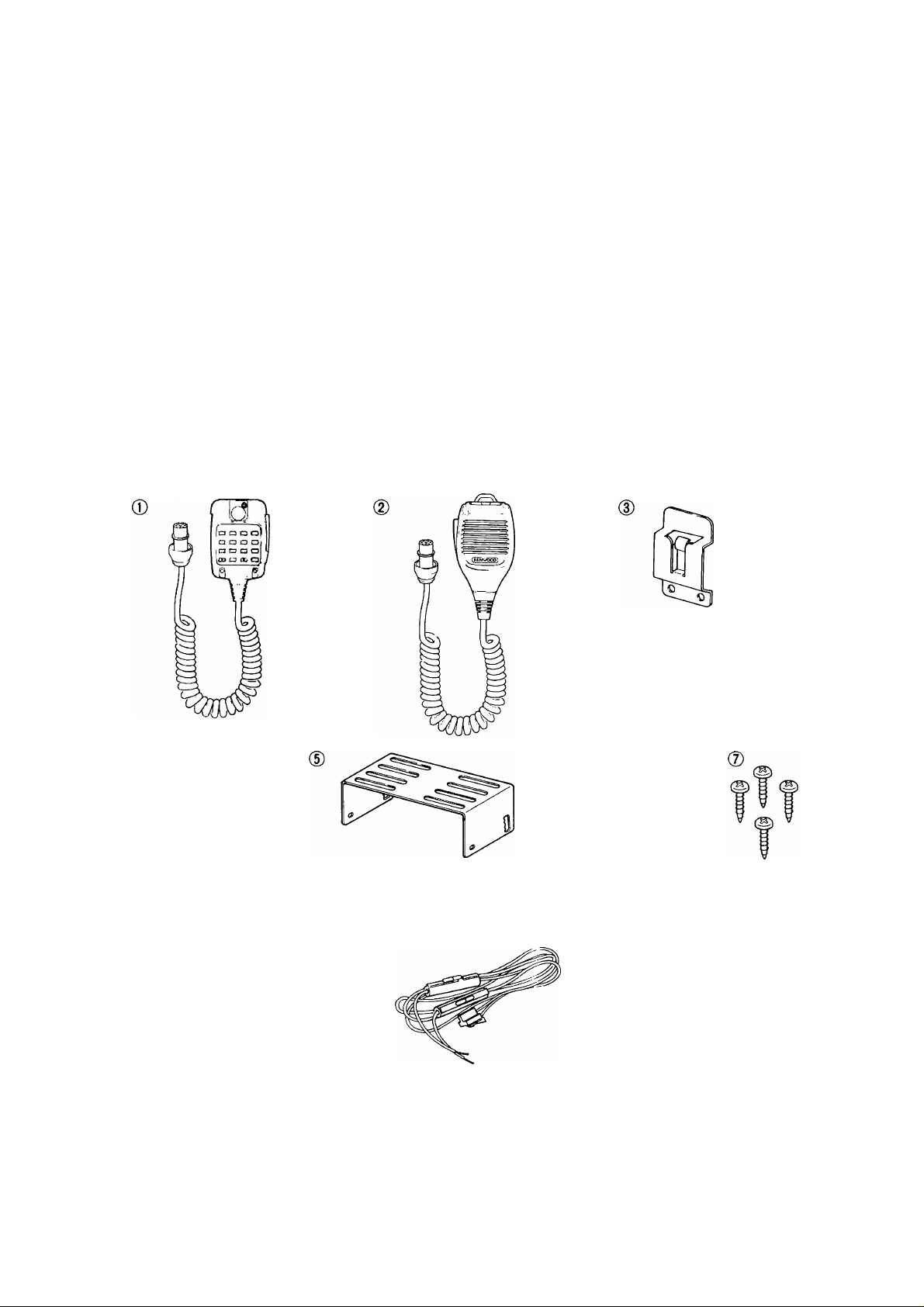
2-2. ACCESSORIES
Please unpack your new transceiver carefully, and confirm that the accessories listed below are included in the
box. If any of the items is missing contact the dealer where the radio was purchased.
® MC-48B DTMF Microphone (U.S.A. version only) ..........................................(T91-0359-05).............................1 ea.
(2) Dynamic Microphone (Except U.S.A. version)
(D Microphone Hook (U.S.A. version only)....................................................................(J20-0319-24).............................1 ea.
0 Self-tapping Screw (U.S.A. version only)
Mobile Mounting Kit
0 Bracket.....................................................................................................................(J29-0416-03).............................1 ea.
0 SEMS Screw............................................................................................................(N09-1530-05)
(7) Self-tapping Screw...............................................................................................(N09-0335-05)
0 Flat Washer...............................................................................................................................................................4 ea.
(D Stacking Plate (TM-421/521 series and TM-321A only)
(TM-221/421 only)..........................................................................(E30-2111-05)
O) DC Power Cable (TM-521/321A only)........................................................................(E30-2053-05)
(Jj) Spare Fuse, 10A (TM-221/421 series only)..............................................................(F05-1031-05).............................1 ea.
(0) Spare Fuse, 8A (TM-321A and TM-521 series only)
Instruction Manual...........................................................................................................(B50-8221-XX)
Warranty Card....................................................................................................................................................................1 ea.
........................................................
...................................................................
...........................................
...............................................
(T91-0365-1 5)............................1 ea.
(N46-3010-46)
(J21-4147-14)
(F05-8021-05).............................1 ea.
............................
............................
............................
...........................
............................
...........................
2 ea.
4 ea.
4 ea.
2 ea.
1 ea.
1 copy
0
0
o o o o
AFTER UNPACKING
Shipping container:
Save the boxes and packing in the event your unit needs to be transported for remote operation, maintenance, or
service.
0
Page 6
3. INSTALLATION AND CONNECTION
Warning:------------------------------------------------------------------------
Never apply AC power to the DC Power Supply until
all installation and connections have been com
pleted.
3-1. INSTALLATION
Cautions:-----------------------------------------------------------------------
1. Do not place the unit in an area that is exposed
to direct sunlight, or near a heater, etc.
2. Do not store or use the unit in a dusty location or
in a moist atmosphere. Select a well ventilated
location.
3. To maintain good ventilation:
Remove all packing materials.
Do not cover the unit.
Place the unit at least 10 cm (4") away from
the walls.
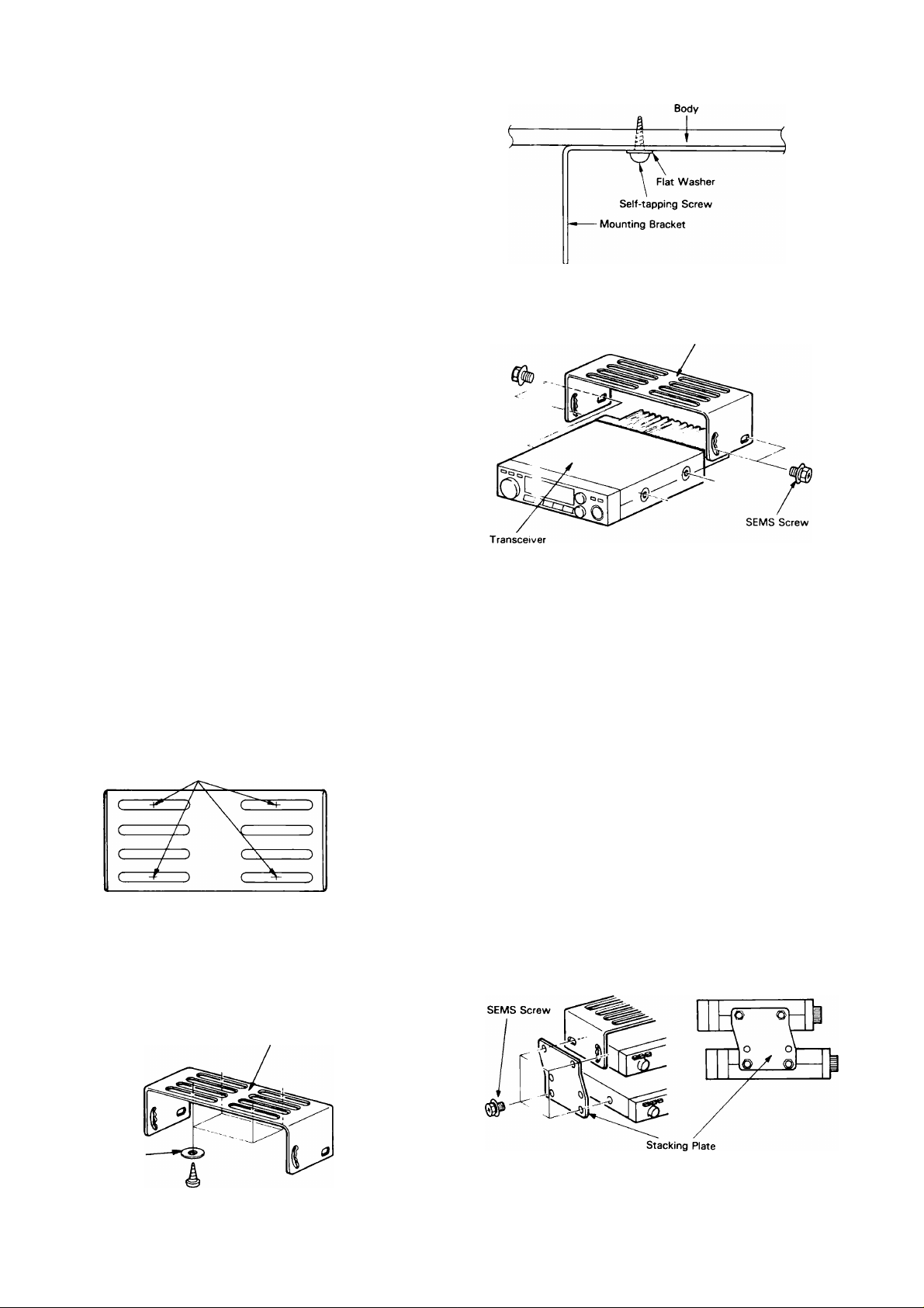
3-1-1. Mounting Bracket Installation (Mobile)
Warning:------------------------------------------------------------------------
Consider ease of operation and safety when select
ing the location for the Mounting Bracket.
Attach the transceiver temporarily using the
SEMS Screws (4 pcs.).
Mounting Bracket
The following tools are required for installing the
Mounting Bracket.
1/6" drill for Self-tapping Screws.
No. 2 Philips Screw Driver.
1. Select a location in which to install the Mounting
Bracket.
2. Use the Mounting Bracket as a template to
locate the holes and mark four points to be drill
ed.
Mark four points.
Drill four holes as marked using a 1/6" drill for
Self-tapping Screws.
Install the Mounting Bracket using the supplied
Self-tapping Screws (4 pcs.) and Flat Washers
(4 pcs.)
Mounting Bracket
The angle of the Mounting Bracket may be ad
justed to any of five (5) possible viewing angles.
Select the desired angle.
Hold the transceiver in place and tighten the four
(4) SEMS Screws using a wrench or screw
driver.
Warning:
-----------------------------------------------------------------
Make sure that the transceiver will not slip out of
place while operating the vehicle.
3-1-2. Stacking Plate
(TM-321A and TM-421/521 series only)
To stack the TM-321A, TM-421 series and/or
TM-521 series with the TM-221 series, connect
them with the supplied Stacking Plate.
Only one Mounting Bracket will be required so save
the other Mounting Bracket and mounting hardware
for future use.
Select the lower pair of mounting holes on the
bracket as shown in the accompanying diagram
when securing the lower radio.
Flat Washer
X
Self-tapping Screw
Page 7
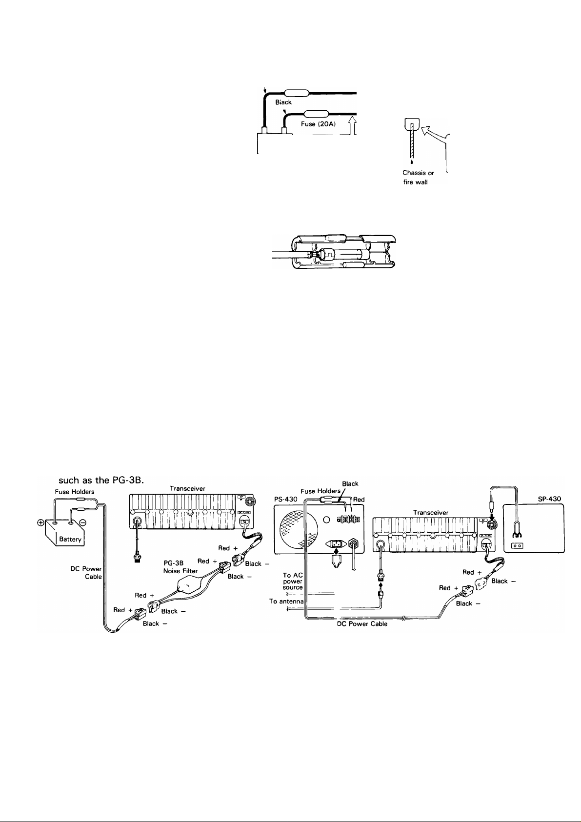
3-2. CONNECTIONS
Cautions:
1. Before connecting or disconnect
2. Observe polarity of the DC
3-2-1. Mobile
1. Battery Connections
Connect the DC Power Cable directly
to the battery terminals. Use of the
cigarette lighter socket can lead to
poor connection, and result in poor
performance. Pay close attention to
the polarity of the cables when con
necting them to the battery.
Cautions:-----------------------------------------------
1. Before installing the DC Power Cable, be sure to
2. After installation and wiring, be sure to double
3. If the fuse opens, be sure to check that each con
---------------------------------------------
Make sure the positive (+) and negative (-) lead polarity are correct
\Aihen wiring to the battery.
ing the DC Power Cable, be sure
to turn off the POWER switches
Red
Fuse (20A)
of both the transceiver and the
DC Power Supply.
Power Cable. The transceiver
operates on 13.8 VDC, negative
ground. The DC Power Cable is
® e
Battery
color coded:
Red ^ -I- (Positive polarity)
Black — (Negative polarity)
remove the negative lead from the battery for
safety. 4.
check for correct installation before reconnect
ing the negative lead to the battery terminal. 5.
ductor has not been damaged by short-
Engine compartment
DC Power Cable
Passenger compartment
_____i_____
Select the location
where the power cable
is protected from heat,
moisture or abrasion.
Secure the cable.
Make sure the cable
does not directly con
tact the edge of the hole
by using a grommet.
If the wiring hole in the fire wall or chassis is too
small, disassemble the fuse holder to thread the
wire through the hole.
From passenger
compartment
Thread like this.
circuiting, etc.
Then replace with a new fuse of the same rating.
After completing the wiring, wrap the fuse
holder with heat resistant tape to protect against
heat and moisture.
Do not remove the fuse even if the power cable
is too long.
To the
1 transceiver
2. Ignition Noise
The transceiver has been designed to suppress
ignition noise; however, if excessive noise is
present, it may be necessary to use suppressor spark
plugs (with resistors), or an external Noise Filter
3-2-3. Antenna
Warning:
-------------
For protection against fire, electric shock, personal
injury, or damage to the radio, use a lightning ar
rester in your antenna lines.
The type of antenna that is used will greatly affect
the performance of the transceiver. Use a properly
adjusted antenna, of good quality, to enable your
transceiver to perform at its best. The antenna input
impedance is 50 ohms. Use 50-ohm VHF/UHF coax
ial cable for this connection. If the antenna is far
3-2-2. Fixed Station
A regulated DC Power Supply (13.8 VDC) is re
quired. The PS-430 and the PS-50 are recommend
ed.
from the transceiver the use of low loss coaxial cable
is recommended. Match the impedance of the coax
ial cable and that of the antenna so that the SWR is
less than 1.5 to 1. The protection circuit in the
transceiver will activate if the SWR is particularly
poor (greater than 3 to 1).
Note:-----------------------------------------------------------------------------
High SWR values will cause the transmitter output to
drop, and may lead to TVI or BCI reports.
Page 8
4. OPERATION
Warning:----------------------------------------------
------------------------------------------------
1. When operating this transceiver mobile, please drive safely.
2. Remove all packing materials before operating this transceiver.
Note;
----------------------------------------------------------------------------------------------------
An internal heterodyne tone resulting from internal mixing may be en
countered at 1244.150 MHz and 1245.050 MHz. (TM-521A/E only)
Note:
4-1. CONTROL FUNCTIONS
4-1-1. Front Panel
(D (2) (D
VFÒ/M M Hz KENWOOD 144MHz FM TRANSCEIVER TM 221 A
- REV + SCAN CTCSS TONE
--------------------------------------------------------------------------------------
The TM-221A front panel is used for illustration purposes.
..CO n n
I
Hu.-i tu
ESSI □□□□□□□□□□□□□□
SHIFT REV
SCAN
CTCSS
TONE
"I Q
(D VFO/M (VFO/Memory Channel) key
This key is used to switch between the VFO and
Memory Channel modes.
0 LOW (HI/LOW) switch
This switch is used to select the desired transmitter
output power level.
(9) (|:
(D M.IN (Memory In) key
This key is used to enter a frequency, offset, etc. in
to the desired Memory Channel. The key is used dur
ing VFO operations only. When this key is pressed
during memory operations the contents of the
memory are transferred to the VFO and switch the
set back to the VFO mode.
This key is also used when programming the offset,
offset frequency, tone frequency (TM-221 A/321 A/
421A/521A only), and CTCSS decode (TM-221 A/
321A/421A/521A only), and operating the ALT
(Auto Lock Tuning) system (TM-521A only).
(D MHz key
Used to change frequencies rapidly. During VFO
operations, pressing this key will cause the kHz
digits to disappear from the display. Rotating the
TUNING control will then change the frequency in 1
MHz steps.
This function will be released by pressing any key or
microphone PTT switch except the LOW (HI/LOW)
and POWER switches. This function is also canceled
5 seconds after the last input from the TUNING con
trol.
0 Display Panel
The LCD displays operation information such as
transmit/receive frequencies, memory channel infor
mation, offset, tone frequency etc. See page 9 for
additional information.
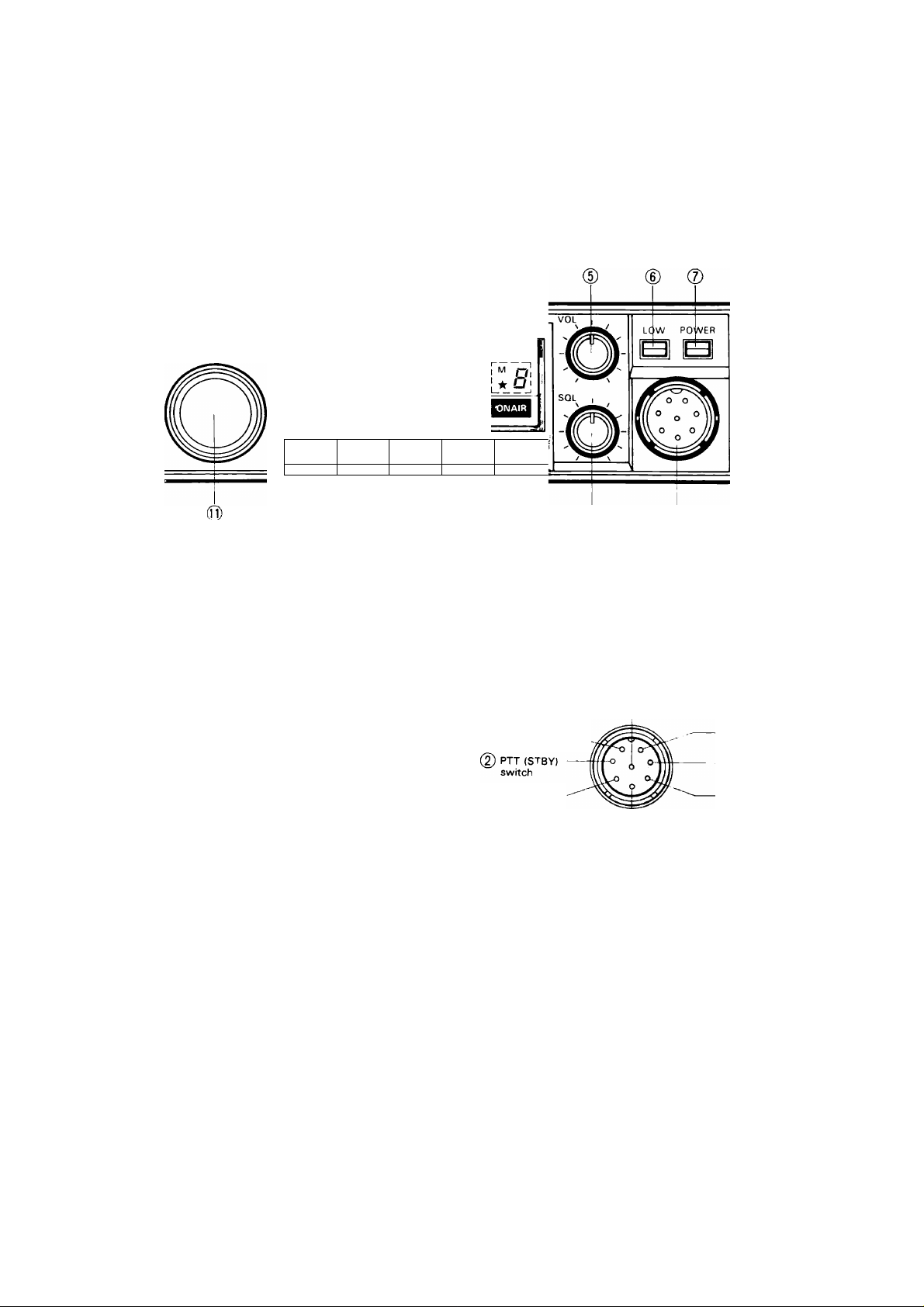
® VOL (Volume) control
Turn the control clockwise to increase the volume
and turn the control counterclockwise to decrease
the volume.
(7) POWER switch
Press to turn on. Press again to turn off.
d) MICROPHONE connector
Plug the standard or optional microphone into this
jack.
(8) gnd (PTT)
(J) Microphone
audio
DOWN
Front view
0 SQL (Squelch) control
0UP
(7) GND (Microphone)
RX detector output
(Approx.
100 mV/10 kil)
0 8 V/Max. 15 mA
The SQL control is used to eliminate noise during no
signal periods. Normally this control is adjusted
clockwise until the noise just disappears, and the
BUSY indicator goes off. (Threshold level)
For scan operations this control must be set to the
threshold point. When an incoming signal is weak or
unstable, readjust the SQL control for optimum
reception.
(jJ) Function keys
See Section 1. Function Keys on page 9.
(Q) TUNING (VFO) control
This control is used to select the desired transmit/
receive frequency. Memory Channel, Frequency
Step, Tone Frequency (TM-221 A/321 A/421 A/
521A only), and Scan Direction.
Page 9
1. Function Keys
With the TM-221A/321A/421A/521A
0 (D
SHIFT
REV '
SCAN
CTCSS
0 0
TONE
0 TONE key
Activates the tone circuit for repeater control. This
key is also used to open the squelch of a distant sta
tion who has activated its CTCSS key. Refer to Sec
tions 4-6 REPEATER and 4-8 TONE SQUELCH
(CTCSS) for additional information on this control.
With the TM-221ES/421ES
SHIFT
With the TM-521E
rev'
SCAN
ALEFIT
TONE
0 0 0 0 0
SHIFT rev'
0
SHIFT key
The SHIFT key is used to select the desired transmit
ter offset during repeater operations. When the key
is pressed, the shift modes cycle from -I- to — [ — to
-----
(European version)] to simplex (no indicator).
(See Section 4-6 REPEATER)
0 REV (Reverse) key
When the REV key is depressed it is used to reverse
the transmit/receive frequencies during repeater
operations.
(With the TM-221A/321A/421A/521A)
This will allow you to check the input of the repeater
or to operate on a reverse repeater pair.
(With the TM-221ES/421ES/521E)
This will allow you to check the input of the repeater.
Transmission is inhibited when the REVERSE key is
engaged.
SCAN alt'
TONE
2. Display Panel
With the TM-221A/321A/421A/521A
Note:
-------------------------------------------------
The TM-221 A Display Panel is used for illustration
purposes.
SCAN CTCSS
TONE
,,, c o n n
(0)-
-S&RF
With the TM-221 ES/421ES/52IE
Note:------------------------------------------
^ ll EBl □□□□□□□□□□□□□□
The TM-221 ES Display Panel is used for illustration
purposes.
U.Ji I u
OVER
•®
0
SCAN key
Press the SCAN key to initiate scanning, press again
to cancel scan. For additional information on this
function refer to Section 4-5 SCAN.
0 CTCSS (Continuous Tone Coded Squelch
System) key (TM-221A/321A/421A/521A only)
Refer to Section 4-8 TONE SQUELCH (CTCSS) for
additional information on this key.
0 ALERT key (TM-221 ES/421ES only)
This switch is used to activate the priority alert func
tion. See Section 4-5-6 Priority Alert for additional
information on this function.
0
ALT key (TM-521E only)
This key is used to activate the Automatic Lock Tun
ing system. See Section 4-2-4 for additional infor
mation on this key.
With the TM-521 series
Note:----------------------------
The TM-521 Display Panel is used for illustration
purposes.
® (D
scan CTCSS
n c n n I«
LJi U U
S&Rf
OVER
Page 10

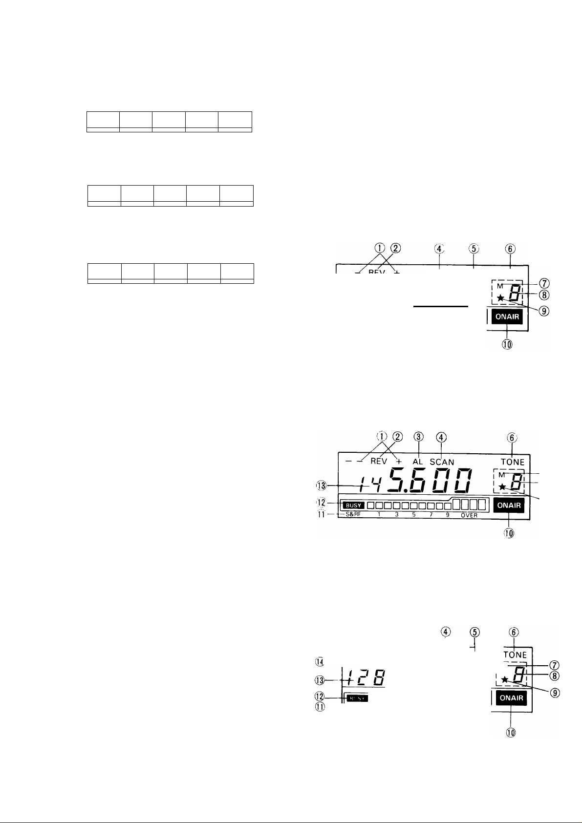
0
SHIFT indicator
Turns on during repeater offset operations. See Sec
tion 4-6 REPEATER for additional information on this
indicator,
(D REV (Reverse) indicator
Turns on when the reverse function has been
selected.
(D
AL (Alert) indicator (TM-221ES/421ES only)
Turns on when the alert function has been selected.
(J|) ALT and Direction indicators (TM-521 series only) ALT indicator:
Turns on to indicate the Auto Lock Tuning function
has been selected.
Direction indicator:
When the ALT system is operating the Direction in
dicator will turn on if the system shifts the receiver
frequency.
Please refer to Section 4-2-4 ALT System for addi
tional information.
0 SCAN indicator
Turns on to indicate the scan function has been
selected.
® CTCSS (Continuous Tone Coded Squelch
System) Indicator (TM-221 A/321A/421A/521A
only)
Turns on to indicate the CTCSS function is active.
® TONE indicator (Excludes TM-221 ES/421 ES
European versions and TM-521E)
Turns on to indicate the tone function is active.
0 M (Memory In) indicator
On whenever the M.IN key has been depressed.
(D
Memory Channel Number display
Indicates the selected Memory Channel Number.
0 ★ indicator
The ★ indicator indicates the Memory Channel cur
rently in the display will be skipped during Memory
Channel scan.
(Q) ON AIR indicator
On during transmit operations.
4-1-2. Rear Panel
0
ANT (Antenna) connector
Attach an antenna with an impedance of 50 ohms to
this connector.
0 SP (Speaker) jack
This jack is for connection of an 8-ohm external
speaker.
(3) Fuse holder
Contains one of the following fuses:
TM-221/421 series : 10A
TM-321A and TM-521 series : 8A
(Q) S & RF meter
This level meter indicates the relative receive input
signal strength or transmitter RF output.
During low power operations this meter functions as
a microphone input level meter to check for proper
microphone operation.
Qj) BUSY indicator
On whenever the squelch is open.
(0) Frequency display
Displays the transmit/receive frequency, Frequency
Step, or Tone Frequency (TM-221 A/321A/421 A/
521A only).
10
0
13.8 VDC power input connector
Connect the supplied DC Power Cable to this con
nector. Pay close attention to the polarity (the DC
Power Cable is color-coded; red is positive and black
is negative), when connecting the cable to the power
source.
4-1-3, Microphone
© ®
Page 11

TM-221A/321A/421A/521A U.S.A. version only
4-2. RECEPTION
4-2-1. Initial Control Settings
1. Connect the power supply and antenna and then
set the witches and controls as follows:
POWER switch : OFF
POWER switch of the DC power supply
(Fixed Station)
VOL control
SQL control
OFF
Fully counterclockwise
Fully counterclockwise
0and (2) UP/DWN (Up/Down) switches
These switches are used to step the VFO frequency
or Memory Channel up and down. The frequency will
change continuously if the switches are pressed and
held.
(D PTT (Push To Talk) switch
The transceiver will be placed into transmit
whenever this switch is pressed. Operations such as
scanning will be cleared when this switch is pressed.
0
16-Tone DTMF Keypad (U.S.A. version only)
Used to activate the DTMF encoder. See Section 4-6
REPEATER for additional information on this item.
2. Turn on the DC power supply and then press the
POWER switch on the radio; the display will in
dicate a frequency.
3. Adjust the VOL control clockwise until a signal
or noise is heard.
4. Rotate the TUNING control and select an open
channel. Then turn the SQL control clockwise
until the noise just disappears.
5. Select the desired frequency using the TUNING
control or UP/DWN switches on the microphone.
(See Section 4-2-2 Frequency and Memory
Channel Selection.)
If a signal is received, the BUSY indicator will
turn on and the S-meter will deflect.
6. To turn off the transceiver, turn off the
transceiver's POWER switch before you turn off
the power supply, or if in a vehicle, before you
stop the engine.
Note:-----------------------------------------------------------------------
The TM-221A front panel is used for illustration
purposes.
Note the initial factory delivered settings for Fre
quency, Tone Frequency, Memory Channel and
Frequency Step are shown in the accompanying
table.
TM-221A TM-221ES
VFO Frequency
Frequency Step
Memory Channel
Memory Channel
Tone Frequency
5 kHz
88.5 Hz
144.000 MHz
12.5 kHz
144.000 MHz
220.000 MHz
220.000 MHz
TM-321A
20 kHz
TM-421A TM-421ES TM-521A TM-521E
440.000 MHz
(U.S.A version)
430.000 MHz
Memory Channel 0
440.000 MHz
(U.S.A. version) 430.000 MHz
430.000 MHz
88.5 Hz
430.000 MHz
1240.000 MHz
25 kHz
1240.000 MHz
88.5 Hz
n
Page 12

4-2-2. Frequency and Memory Channel Selec
tion
The desired operating frequency and the Memory
Channel may be selected by using either the TUNING
control or the microphone UP/DWN switches. Press
the VFO/M key to alternate between the VFO and
the Memory Channel modes.
(Example)
Frequency
Transmit Frequency Receive Frequency
of the Distant Station
|ALT System is[
performed.
4-2-3. Frequency Step Selection
The frequency step can be selected by using the
following procedure:
1. Press the VFO/M key to select the VFO mode.
2.
Press the M.IN key and then the REV key.
Whenever the M.IN key is pressed, the M in
dicator will turn on. You must complete the
desired action within 5 seconds, or the M in
dicator will turn off. If the indicator goes off, you
must press the M.IN key again.
Select the desired frequency step using the TUN
3.
ING control or the microphone UP/DWN
switches. The figure below shows how the TUN
ING control and UP/DWN switches will increase
or decrease in size.
Turn the TUNING control
counterclockwise or press
the microphone UP switch.
With the TM-221A
-------
25kHz
-----------
-20kHz-
With the TM-221ES
-------
25kHz
-------------
-20kHz-
With the TM-321A
-------
15kHz
------------
•10kHz-
Wlth the TM-421 series
------
20kHz------------------------25kHz-
15kHz-
With the TM-521 series
Í
12.5kHz
I
_________________
-12.5kHz-
-15kHz-
-20kHz-
-10kHz-
-25kHz
-20kHz-
Turn the TUNING control
clockwise or press the
microphone OWN switch.
■5kHz-
--------------------
10kHz
-15kHz-
-5kHz-
-10kHz-
-25kHz-
-5kHz-
■12.5kHz-
-5kHz
----------
10kHz
_J
1
4, To return to the normal receive frequency, press
any key except the LOW or the POWER
switches, or turn the TUNING control.
4-2-4. ALT (Auto Lock Tuning) System (TM-521
series only)
The ALT system operates similar to an AFC
(Automatic Frequency Control) system. This system
is useful when the frequency of either station starts
to drift. When this occurs distortion of the signal is
the usual result. The ALT system will correct for this
apparent drift.
Frequency
Transmit Frequency Receive Frequency
of the Distant Station
Note:-----------------------------------------------------------------------------
The frequency display will not change, even though
the receive frequency might shift in order to properly
tune the incoming signal. When the ALT system is
operating the Direction indicator will turn on if the
system shifts the receiver frequency. The Direction
indicator will show you if the incoming signal was
higher or lower than the displayed frequency.
Turns on when the transmit
frequency of the distant sta
tion is higher than your receive
frequency.
I d B f.Ji U U
MmM □□□□□□□□□□□□□□
S&Rf
Turns on when the transmit
frequency of the distant sta
tion is lower than your receive
frequency.
n c n n
^ Oi
_^y_!
To utilize this feature:
(With the TM-521 A)
1. Press the M.IN key. The M indicator will turn on
for 5 seconds.
2. While the M indicator is on press the SHIFT key.
If you do not press the SHIFT key while the M in
dicator is on you will have to start over at step
one. The ALT indicator will turn on and the
receiver will automatically center itself on the in
coming signal.
M.IN key
'/Fo/M M. N MH, KENWOOD izooMHg fm transceiver tm-szia
n r n n r
i£B I.2UU L
[EBl □□□□□□□□□□□□[/]□ 1
SHIFT
REV SCAN
M indicator
cress
★ Pj
TONE
3. To release the ALT system, press the M.IN key
and then the SHIFT key. The ALT and the Direc
tion indicators will turn off.
12
Page 13

(With the TM-521E)
1. Press the ALT key. The ALT indicator will turn on
and the receiver will automatically center itself
on the incoming signal.
2. To release the ALT system, press the ALT key.
The ALT and the Direction indicators will turn
off.
■ ALT operation using the RC-10.
Use the following procedure to turn on the ALT func
tion with the RC-10 Remote Controller.
1. Press the F key. The F indicator will turn on for 5
seconds.
2. While the F indicator is on, press the 1 key. If
you do not press the 1 key while the F indicator
is on you will have to start over at step 1.
To release ALT System operation, repeat steps 1
and 2. Please refer to the Instruction Manual provid
ed with the RC-10 for instructions on programming
other RC-10 functions.
4-2-5. Confirmation Tones
An audible tone will sound whenever the TUNING
control is rotated (except in the VFO and Memory
Channel modes), or any keys or the microphone
UP/DWN switches are depressed. If you do not want
this audio confirmation, press the M.IN key and then
the CTCSS (ALERT with the U.K. and European ver
sions) key. Whenever the M.IN key is pressed, the M
indicator will turn on. You must complete the desired
action within 5 seconds, or the M indicator will turn
off. If the indicator goes off, you must press the
M.IN key again.
To restore the confirmation tone press the M.IN key
and then the CTCSS (ALERT) key again.
4-3. TRANSMISSION
Cautions:-----------------------------------------------------------------------
1. Ensure that an antenna with a low standing
wave ratio (SWR) is attached to the antenna
connector before attempting to transmit. Failure
to provide proper termination may result in
damage to the final amplifier section.
2. Always check to ensure the frequency is clear
before transmitting.
1. Select the desired operating frequency using any
of the methods described above.
2. Check the frequency to see if it is occupied
before you transmit.
3. Press the microphone PTT switch. The ON AIR
indicator will light.
4. Speak into the microphone. The recommended
distance to the microphone is 2 inches (5 cm).
Talking too far away may result in reports of
weak audio.
5. Release the microphone PTT switch to return to
the receive mode. The ON AIR indicator should
go out.
4-4. MEMORY
4-4-1. Microprocessor Reset
A lithium battery is contained in the transceiver to re
tain memory. Turning off the POWER switch,
disconnecting the power cable, or a power failure
will not erase memory. The battery should last for
approximately five years. For replacement informa
tion please refer to Section 5-5 MICROPROCESSOR
BACKUP LITHIUM BATTERY REPLACEMENT.
4-4-2. Microprocessor Initialization
When you want to erase all programmed data, or if
the display should show erroneous information, you
should reset (initialize) the microprocessor using the
following procedure.
1. Turn the POWER switch off.
2. Press and hold the VFO/M and the M.IN keys and
turn on the POWER switch.
VFO/M_^M.IN MHz
3. Release the VFO/M and the M.IN keys; the M in
dicator and the Memory Channel Number will
display for approximately 5 seconds after you
release the keys.
4-4-3. Memory Channel
This transceiver provides 14 Memory Channels
(0-9, A-d). In addition to serving as a normal memory
channel some of the Memory Channels serve a dual
purpose to specify other parameters. The functions
of these Memory Channels are described below.
* Memory Channel 1 is used to store the frequen
cy for the Priority Alert function. (TM-221ES/
421ES only)
* Memory Channel A is used to store the lower
limit for the Programmable Band Scan function.
* Memory Channel b is used to store the upper
limit for the Programmable Band Scan function.
* Memory Channels C and d are used to store odd
split repeater data.
* *
LOW POWER
B
13
Page 14

4-4-4. Memory Channel Contents
The following data can be stored in each Memory
Channel.
Model
TM-221A
TM-321A
TM-421A
TM-521A
TM-221ES
TM-421ES
TM-521E REV status
Memory Channel Contents
Frequency
SHIFT status
REV status
TONE status
Tone Frequency
CTCSS status and Tone Frequency
Frequency
SHIFT status
4-4-5. Memory Entry
1. Memory Channels 0 — 9, A and b (Simplex/Stan-
dard Offsets)
1. Press the VFO/M key to select the VFO mode.
2. Select the desired operating frequency, and
shift.
3. Select the CTCSS key if tone squelch is desired.
(TM-221A/321A/421A/521A only)
4. Press the TONE key if required. (European ver
sion excluded)
5. Select the desired Tone Frequency. See Section
4-7. TONE FREQUENCY SELECTION. If CTCSS
(Tone Squelch) has been selected, the tone func
tion will be automatically activated. (TM-221A/
321A/421A/521A only).
6. Press the M.IN key. The Memory Channel
Number display will light.
7. Select the desired Memory Channel using the
TUNING control or the microphone UP/DWN
switches. You must do this within 5 seconds of
pressing the M.IN key (Step 6), or the M in
dicator will turn off. If the indicator goes off, you
must press the M.IN key again.
8. Press the M.IN key within 5 seconds of selecting
the Memory Channel. If the indicator goes off,
you must press the M.IN key again in order to
complete the desired function.
Odd Split Memory Channels C and d
2.
Enter the desired receiver frequency as describ
1.
ed in Section 4-4-5. 1. above, in Memory Chan
nel C or d.
Select the desired transmitter frequency using
2.
the TUNING control or the microphone UP/DWN
switches.
Press the M.IN key to complete the operation.
3.
4-4-6. Memory Shift (Transferring Data from
Memory Channel to the VFO)
1. Press the VFO/M key to select the Memory
Channel mode.
2. Select the desired Memory Channel. If an Odd
Split Memory Channel (C or d) is selected, only
the receive data will be transferred.
3. Press the M.IN key and then the VFO/M key to
transfer the data.
4-5. SCAN
The following scan options are available:
Programmable Band Scan (VFO mode)
Memory Channel Scan (Memory Channel mode)
4-5-1. Programmable Band Scan
The scan frequency range is determined by the fre
quencies stored in Memory Channels A and b. The
frequency stored in Memory Channel A must be
lower than the frequency stored in Memory Channel
b for Programmable Band Scan to function properly.
If the frequency in Memory Channel A is equal to or
greater than the frequency stored in Memory Chan
nel b, scan will proceed over the entire tuning range
of the radio.
Lowest
Operating Frequency entered in
Frequency Memory Channel A.
(a) I
-----------------^-----------------------
The radio scans this frequency range.
Lowest
Operating
Frequency
(b) I
Lowest
Operating Same frequencies are entered in
Frequency both Memory Channels A and b.
(0 I
Frequency entered in
Memory Channel b.
------
K
----------------
h -
The radio scans this frequency range.
^----------------------------------------------
-------------
The radio scans this frequency range.
Frequency entered in Operating
Memory Channel b. Frequency
Frequency entered in Operating
Memory Channel A. Frequency
--------------- ----------
1. Before pressing the SCAN key, adjust the SQL
control to the threshold level.
2. Determine the desired scan frequency range and
enter the frequencies into Memory Channels A
and b.
3. Press the VFO/M key to select the VFO mode.
4. Press the SCAN key to initiate scan.
5. To clear scanning, press any key such as the
SCAN key, microphone PTT or UP/DWN
switches, or rotate the TUNING control, except
LOW (HI/LO) or POWER switch.
4-5-2. Memory Channel Scan
1. Press the VFO/M key to select the Memory
Channel mode.
2. Before pressing the SCAN key, adjust the SQL
control to the threshold level.
3. Press the SCAN key to initiate scan.
4. To clear scanning, press any key such as the
SCAN key, microphone PTT or UP/DWN
switches, or rotate the TUNING control, except
LOW (HI/LO) or POWER switch.
Highest
Highest
■H
Highest
Operating
Frequency
14
Page 15

4-5-3. Scan Direction
Scanning begins in the direction that corresponds to
the direction that the TUNING control was last turn
ed, or with respect to which of the microphone
UP/DWN switches was last depressed. If you press
ed the UP switch before initiating scan, scan will pro
ceed in a positive direction. If the DWN switch was
pressed scan will tune down in frequency.
4-5-4. Scan Hold
The transceiver will stop on a busy channel and then
resume after a 5-second delay. You must cancel
scan operations to remain on the channel.
4-5-5. Memory Channel Lockout
The Memory Channel Lockout function allows you to
temporarily skip unwanted Memory Channels during
the Memory Channel Scan mode.
1. Press the VFO/M key to select the Memory
Channel mode.
2. Select the Memory Channel that you want to
skip using the TUNING control or the UP/DWN
switches.
4-6. REPEATER
4-6-1. Transmitter Offsets
All amateur radio repeaters utilize a separate receiver
and transmitter section. The receiver frequency may
be either above or below the transmitter frequency.
For most repeater's offsets are as follows:
TRANSMITTER OFFSET FREQUENCY
Display + Model
TM-221 series
TM-321A
TM-421A
TM-421ES
TM-521A
TM-521E
European
market
U.K.
market
-{*)
+ 600 kHz
-M.6 MHz
+ 5 MHz
*-1.6 MHz
+ ^.6 MHz
+ 12 MHz
+ 35 MHz
-600 kHz
-1.6 MHz
-5 MHz
*-7.6 MHz
-1.6 MHz
-12 MHz
-6 MHz
3. Press the M.IN key and then the SCAN key.
Whenever the M.IN key is pressed, the M in
dicator will turn on. You must complete the
desired action within 5 seconds, or the M in
dicator will turn off. If the indicator goes off, you
must press the M.IN key again. A star (★ ) will
appear to the left of the Memory Channel
Number. This indicates the Memory Channel will
be skipped during scan operations.
4. To cancel the Memory Channel Lockout press
the M.IN key and then the SCAN key.
4- 5-6. Priority Alert (TM-221ES/421ES only)
Memory Channel 1 will be checked at approximately
5- second intervals to check for activity. If the fre
quency is occupied, a beep will sound. If the audio
confirmation function has been turned off, no beep
will sound, even if Memory Channel 1 is busy.
Pressing the ALERT key will switch this function off
and on.
Note:
----------------------------------------------------------------------------
The alert function will not work when the RC-10 is
connected to the TM-221 ES/421 ES.
This transceiver allows you to store the frequency,
and offset direction in Memory Channels 0 — 9, and
A —b, or you can select these functions directly from
the keyboard.
(With the TM-221 A/321 A)
The TM-221 A/321 A have been programmed accor
ding to the standard ARRL Band Plan, regarding
transmitter offsets. Please see the enclosed charts
for additional information. You can, of course, over
ride this by using the SHIFT function, if desired.
With the TM-221 A
144.00 145.10 145.50 146.00 146.40 146.60 147.00 147.40 147.60 148.00 (MHz)
s
+
—
S: Simplex Channel
With the TM-321A
220.000
S: Simplex Channel
S
—
s +
s
—
223.940
224.995 (MHz)
15
Page 16

4-6-2. Offset Direction
To select the desired transmitter offset direction
press the SHIFT key. Each time you press the key the
radio will advance from one offset to the other, i.e.
"-h" to to with TM-421ES Euro
pean version) to no offset (simplex).
4-6-3. Reverse Function
Some repeaters utilize a "Reverse Pair", i.e. the
transmit/receive frequencies are exactly the reverse
of another repeater. For example repeater A uses
146.000 for a transmit frequency (OUTPUT) and
146.600 for receive (INPUT). Repeater B uses
146.000 for its receive and 146.600 for its
transmit frequency. It would be inconvenient to have
to reprogram the radio each time if you were in range
of both repeaters.
The REV key has been provided to allow you to
reverse the transmit and receive frequencies.
To use the Reverse function press the REV key. The
REV indicator will light in the Display Panel to remind
you that you are working a reverse repeater pair.
To return to normal offsets press the REV key again.
This function is also useful to check the input fre
quency of the repeater, so that you can determine if
you are within simplex communications range.
4-6-5. Autopatch (U.S.A. only)
Some repeaters offer a service known as autopatch.
This allows you to dial a telephone number from your
radio and carry out a telephone conversation, much
like a car telephone, or cellular telephone. This func
tion requires the use of a DTMF (Dual Tone Multi Fre
quency) pad. In addition to the normal 12 keys that
are found on your telephone the MC-48B
microphone also provides 4 additional keys. A, B, C,
and D. These keys are required by some repeater
systems for various control functions. You should
check with the control operator of your repeater to
determine if their use is required. A chart is provided
that lists the tones that are generated when you
press each key.
(With the TM-221ES/421ES/521E)
Transmission is inhibited when the REV key is
engaged.
4-6-4. Tone Operations
Some repeaters require the use of a control signal to
activate the repeater. Several versions are currently
in use worldwide.
(With the TM-221A/321A/421A/521A)
Subaudible tones are sometimes used. In the United
States 38 different subaudible tone frequency selec
tions are possible. (See Section 4-7 TONE FRE
QUENCY SELECTION)
(With the TM-221ES/421ES/521E)
In Europe a 1750 Hz tone is used in transmit. Press
the TONE key to transmit the access tone, then
press the PTT switch.
In the United Kingdom a 1750 Hz tone burst at the
beginning of each transmission is used.
Since use of this tone is required in the Europe and
the United Kingdom, an 1750 Hz tone encoder is in
cluded as standard equipment.
To activate the DTMF pad, press and hold the
PTT switch.
2.
Now press the keys just as you would dial a
telephone.
3.
The radio will remain keyed for about 2 seconds
after you press each number, so you can release
the PTT switch without unkeying the radio.
AUDIO TONES
v^igh Tone
Low
Tone (Hz)
697 1
770 4
852
941
1209
1336 1477 1633
2
5
7
♦
8
0
3
6
9 C
#
A
B
D
16
Page 17

4-7. TONE FREQUENCY SELECTION
(TM-221A/321A/421A/521A only)
1. To select the Tone Frequency press the M.IN key
and then the TONE key. The Display Panel will
indicate a Tone Frequency. Whenever the M.IN
key is pressed, the M indicator will turn on. You
must complete the desired action within 5
seconds, or the M indicator will turn off. If the in
dicator goes off, you must press the M.IN key
again.
2. Select the desired Tone Frequency using the
UP/DWN switches on the microphone or the
TUNING control.
Available CTCSS Tone Frequencies
Hz
67.0
71.9
74.4
77.0
79.7
82.5
85.4
88.5
91.5
94.8
97.4 162.2
100.0
103.5
107.2
110.9
Press any key or the PTT switch on the
microphone to return to the receiver frequency
display. A tone will be transmitted whenever the
PTT switch is depressed.
Hz Hz
114.8
118.8
123.0 210.7
127.3 218.1
131.8 225.7
136.5
141.3
146.2
151.4
156.7
167.9
173.8
179.9
186.2
192.8
203.5
233.6
241.8
250.3
4-8. TONE SQUELCH (CTCSS)
(TM-221A/321A/421A/521A only)
4-8-1. Tone Squelch Operation Initiated by the Dis
tant Station.
Note:-----------------------------------------------------------------------------
This function requires the use of the optional TSU-5
Programmable Tone Decoder Unit.
This function allows you to remain squelched until
the proper Tone Frequency is received. If you are on
a busy repeater this can be quite an aid.
1. Press the CTCSS key. The CTCSS indicator will
light in the Display Panel.
2. Your radio will now remain squelched until the
proper code is received. You should ensure all
the stations you wish to communicate with use
the same Tone Frequency. Please note that the
97.4 Hz Tone does not function for decode pur
poses. Please see Section 4-7 TONE FREQUEN
CY SELECTION for programming the CTCSS
Tone Frequency.
3. To release the Tone Squelch function (normal
noise activated squelch), press the CTCSS key
again. The CTCSS indicator should go out on the
Display Panel.
4-8-2. To Open the Tone Squelch of a Distant Sta
tion
Even if the optional TSU-5 Programmable Tone
Decoder Unit is not installed, your radio can open the
Tone Squelch of a distant station.
1. Press the CTCSS key. The CTCSS indicator will
light in the Display Panel.
Select the same Tone Frequency between the
2.
stations you wish to communicate. See Section
4-7 TONE FREQUENCY SELECTION.
Press the microphone PTT switch.
To release the Tone Squelch function, press the
CTCSS key again. The CTCSS indicator should
go out on the Display Panel.
17
Page 18

5. MAINTENANCE AND ADJUSTMENT
5-1. GENERAL INFORMATION
Your transceiver has been factory aligned and tested
to specification before shipment. Under normal cir
cumstances the transceiver will operate in accord
ance with these operating instructions. All ad
justable trimmers and coils in your transceiver were
preset at the factory and should only be readjusted
by a qualified technician with proper test equipment.
Attempting service or alignment without factory
authorization can void the transceiver's warranty.
When operated properly, the transceiver will provide
many years of service without requiring realignment.
The information in this section gives some general
service procedures which can be accomplished
without sophisticated test equipment.
5-2. SERVICE
Should it ever become necessary to return the equip
ment to your dealer or service center for repair, pack
it in its original box and packing, and include a full
description of the problems involved. Also include
your telephone number. You need not return ac
cessory items unless directly related to the service
problem.
Service note:------------------------------------------------------------------
Dear OM, if you desire to correspond on a technical
or operational problem, please make your note short,
complete, and to the point, and PLEASE make it
readable.
Please list:
Model and Serial Number
The problem you are having.
Please give sufficient detail to diagnose. Information
such as other equipment in the station, meter
readings and anything else you feel might be useful
in attempting diagnosis.
Caution:
------------------------------------------------------------------------
Do not pack the equipment in crushed newspapers
for shipment. Extensive damage may result during
shipment.
Notes:---------------------------------------------------------------------------
1. When claiming warranty service, please include
a photocopy of the bill of sale, or other proof of
purchase showing the date of sale must accom
pany the radio.
2. Record the Date of Purchase, Serial Number and
Dealer from whom purchased.
3. For your own information, retain a written record
of any maintenance performed on the unit.
5-3. CLEANING
The knobs, front panel and cabinet of the transceiver
are likely to become soiled after extended use. The
knobs should be removed from the transceiver and
cleaned with a neutral soap and warm water. Use a
neutral soap (no harsh chemicals) and a damp cloth
to clean the cabinet and front panel.
5-4. IN CASE OF DIFFICULTY
5-4-1. Receive
SYMPTOM
Indicator does not light and data is
not displayed when POWER switch
is pressed.
Display is dark.
No sound from the speaker. No
signal can be received.
Scan fails.
Memory can not be backed up.
5-4-2. Transmit
SYMPTOM
No output.
Can not access to repeater.
PROBABLE CAUSE
1. Wrong power polarity.
2. Fuse is blown.
Power voltage is low.
1. VOL control is turned too far
counterclockwise.
2. Squelch is closed.
3. PTT switch of microphone is pressed
setting the unit in the transmit mode.
4. CTCSS is operating.
Improper scan control setting, such as
SQL control adjustment.
Backup battery voltage is low. See Section 5-5.
PROBABLE CAUSE ACTION
1. Microphone jack is not plugged in. 1. Plug jack in.
2. Poor antenna connection. 2. Connect antenna securely.
1. Setting of the TONE, SHIFT, REV
keys are wrong.
2. Wrong Tone Frequency is selected. 2. Refer to Section 4-7.
1. Connect red to “ + " and black to
2. Replace with the specified fuse after
repairing the cause.
For the fuse rating, see Sections 5-6.
Check voltage for 13.8 VDC± 1 5%
1. Turn the VOL control.
2. Turn the SQL control counterclock
wise.
3. Turn PTT switch off.
4. Press the CTCSS key.
See Section 4-5.
1. Refer to Section 4-6.
ACTION
18
Page 19

5-5. MICROPROCESSOR BACKUP
LITHIUM BATTERY REPLACEMENT
Lithium battery replacement should be performed by
an authorized KENWOOD service facility; either your
KENWOOD dealer, or the factory, since this unit con
tains CMOS type circuitry.
Notes:-----------------------------------------------------------------------
When the lithium battery is
1
microprocessor must be reset,
replaced,
using the
the
pro-
cedure in Section 4-4-2.
When the lithium battery fails, the radio's
2.
microcoded functions are not affected. Only in
formation stored in memory will be cleared.
5-6. FUSE REPLACEMENT
If the fuse blows;
DISCONNECT the AC Power Cable and replace
with the specified fuse only after determining the
cause, or contact either your KENWOOD dealer,
or the factory to repair the cause.
Warning:------------------------------------------------------------------------
1. Never connect the AC cable to the AC outlet until fuse replacement has been made.
Never use a large amperage fuse. Replace with a
2.
new fuse of the same rating.
This transceiver is equipped with the fuse(s) listed
below. If the fuse blows, determine the cause before
replacing the defective fuse. (Replacement fuses are
available from your authorized KENWOOD dealer.)
Fuse Location
*13.8VDC Power
Input Cable
DC Power Cable
Part Number
F05-1031-05 (10 A)
for TM-221/421 series only
F05-8021-05 (8 A)
for TM-321A and TM-521
series only
F05-2036-05 (20 A)
Q'ty
1 ea.
2 ea.
5-7. ORDERING SPARE PARTS
When ordering replacement or spare parts for your
equipment, be sure to specify the following:
Model and serial number of your transceiver.
Schematic number of the part.
Printed circuit board number on which the part is
located.
Part number and name, if known, and quantity
desired.
Part numbers for most replacement parts is contain
ed in the service manual (available as an option from
your dealer).
5-8. ADJUSTMENTS
5-8-1. Cover Removal
Caution:
1. Before removing the top cover, turn the power
2. Do not pinch wiring when closing the cover.
1 Loosen the four screws on both the right and left
5-8-2. Low Power Output
Adjust VR7 on PC board to adjust the output of the
transceiver in the low power position. The adjust
ment range is 1 to 30 watts on the TM-221 series, 1
to 20 watts on the TM-321A and TM-421 series,
and 0.5 to 5 watts on the TM-521 series.
5-8-3. Microphone Gain
Adjust VR3 on PC board to the desired level.
Caution:
Too much microphone gain can cause reports of
audio distortion.
------------------------------------------------------------------------
supply and radio POWER switches off, and
disconnect the Power Cable.
sides.
Remove the four screws attaching the top cover.
Remove the top cover and set aside.
Reverse steps 1 and 2 to reassemble the radio.
------------------------------------------------------------
wm
T ransceiver
19
Page 20

6. OPTIONAL ACCESSORIES
Note:-----------------------------------------------------------------------------
Some optional accessories may not be available in
your area.
6-1. TSU-5 PROGRAMMABLE TONE
DECODER UNIT
(TM-221A/321A/421A/521A only)
Caution:
1. Before removing the top cover, turn the power
2. Do not pinch wiring when closing the cover.
Installation
10. Tighten the four side screws.
------------------------------------------------------------------------
supply and radio POWER switches off, and
disconnect the Power Cable.
1. Loosen the four screws on both the right and left
sides.
2. Remove the four screws attaching the top cover.
Remove the top cover and set aside.
3. Temporarily set the speaker aside.
4. Remove the jumper as shown in the illustration.
5. Connect the 7-pin connector to the TSU-5 as
shown in the accompanying illustration.
6. Install the TSU-5 using the two screws provided.
7. Route the 2-pin connector attached to the
TSU-5 as shown in the accompanying illustra
tion, and attach it to the same plug that the
jumper wire was removed from in step 3.
8. Replace the speaker. Make sure that the chassis
fits in the guides on the back of the speaker
assembly.
9. Attach the top cover using four screws.
6-2. MC-43S HAND MICROPHONE (8-pin)
Caution:-------------------------------------------------------------------------
Some of the early versions of the MC-43S UP/DWN
Microphone were delivered with a wire connected
between the microphone hook and pin number 6
(six) of the microphone connector.
This wire is used on some foreign transceivers and
must be disconnected before the microphone can be
used with the TM-221/421/521 series and TM321A radios. If you connect this microphone to the
TM-221/421/521 series and TM-321A before
checking for this wire there is a possibility that you
may experience erratic display or operation of the
TM-221/421/521 series and TM-321A by static
discharge.
20
Page 21

6-3. OTHER ACCESSORIES
■ PS-430 DC POWER SUPPLY
May be used with the TM-221/421/521 series and
TM-321A for stable operation.
■ SP-430 EXTERNAL SPEAKER
The SP-430 is an attractive, compact external
speaker. This low-distortion speaker provides clear
reproduction of the high-quality audio obtained from
the transceiver.
PS-430
■ PS-50 HEAVY DUTY DC POWER SUPPLY
May be used with the TM-221/421/521 series and
TM-321 A for stable operation.
PS-50
SP-430
■ SP-50B MOBILE SPEAKER (8 ohms)
Compact and smart high quality external speaker
provides flexibility of installation for maximum con
venience.
SP-41 MOBILE SPEAKER (4 ohms)
SP-41
21
Page 22

■ MC-85 MICROPHONE (8-pin)
The MC-85 is a unidirectional high-class electret
condenser microphone provided with the output
selective switch, audio level compensation circuit,
low cut filter, level meter, PTT and LOCK switches.
MC-85
■ MC-80 MICROPHONE (8-pin)
The MC-80 is an omnidirectional electret condenser
microphone provided with UP/DOWN switches,
volume adjustment for output level, PTT and LOCK
switches, built-in pre-amplifier.
■ MC-55 MOBILE MICROPHONE (8-pin)
The MC-55 provides UP/DOWN switches, LED
display for switching transmit or receive, adjustable
microphone gain, automatic receive returning circuit
(approx. 5 minutes) and many functions.
MC-55
■ MC-48B AUTOPATCH UP/DOWN HAND
MICROPHONE (8-pin)
The MC-48B is 16-key autopatch Up/Down
microphone with PTT switch. Encodes 16 autopatch
tones. UP/DWN switches provide step frequency
change, or initiate band scan in the appropriate
direction, if held depressed momentarily.
MC-80
■ MC-60A MICROPHONE (8-pin)
The zinc die-cast base provides high stability, and
the MC-60A is complete with PTT and LOCK
switches, UP/DOWN switches, and impedance
selector switch and a built-in pre-amplifier.
MC-60A
MC-48B
HS-7 MICRO HEADPHONES (16 ohms)
HS-7
22
Page 23

■ SW-200A/200B SWR/POWER METER (supplied
with a coupler)
SW-200A supplied with SWC-1. SW-200B supplied
with SWC-2. Selectable peak-reading/RMS.
SWR/POWER meters cover 1.8 ~ 1 50 MHz (SW200A), 140 — 450 MHz (SW-200B) in range of
0-20/200W, full scale for base station use.
SW-200A/200B
■ SWC-4 DIRECTIONAL COUPLER
The SWC-4 Directional Coupler is designed for use in
conjunction with the SW-200A/200B SWR/POWER
Meters to cover 1200 — 1300 MHz, The coupler is
capable of handling a maximum input of 20 W.
■ SW-100A/100B SWR/POWER METER
Compact and lightweight SWR/POWER/VOLT
meters cover 1.8 —150MHz (SW-100A),
140-450 MHz (SW-100B) in range of 1 50W full
scale for mobile use.
SW-100A/100B
■ SWT-1/SWT-2 ANTENNA TUNING UNIT
The SWT-1 (2m band) and the SWT-2 (70 cm band)
are an antenna tuning unit designed for use in con
junction with an SWR/POWER meter to allow effi
cient transmission. This unit is especially convenient
for monitoring SWR, using a KENWOOD
SWR/POWER meter.
■ RC-10 REMOTE CONTROLLER
The RC-10 Remote Controller provides the following
functions.
1. Direct entry of the desired Transmit/Receive Fre
quencies using the numeric keypad.
2. Transmit/Receive Frequency or Memory Channels
up or down control.
3. 16-key autopatch operation.
4. Volume control
5. Squelch on or off control.
6. When connected to two transceivers allows
duplex communications.
7. ALT System operation (TM-521 series only)
For additional information, please refer to the In
struction Manual provided with the RC-10,
RC-10
SWT-1/SWT-2
■ MB-201 MOBILE MOUNT
The mobile mount MB-201 allows easy installation
and removal of the TM-221/421/521 series and
TM-321A.
■ PG-4G EXTENSION CORD
May be used with the RC-10 to connect a second
transceiver for duplex operation.
■ PG-3B DC LINE NOISE FILTER
May be used with the TM-221/421/521 series and
TM-321A to suppress ignition noise.
PG-2N EXTRA DC POWER CABLE
23
Page 24

7. BLOCK DIAGRAM AND CIRCUIT DIAGRAM
7-1. BLOCK DIAGRAM
7-1-1. TM-221 series
24
Note:
Block Diagram is subject to change without notice due to advancements in technology.
Page 25

7-1-4. TM-521 series
Note:
Block Diagram is subject to change without notice due to advancements in technology.
25
Page 26

8. REFERENCE
8-1. ANTENNA
8-1-1. Fixed Station
Various types of fixed station antennas are commer
cially available. Select your antenna according to
available space and intended application.
Transceiver performance depends largely on the
Yagi antennas
Rotor control cable
type of antenna used. For fixed station operation
there are ground plane antennas (omnidirectional)
and Yagi antennas (unidirectional). The Yagi antenna
is suitable for DX (Long distance) operation or com
munication with a specific party.
Tower
8-1-2. Mobile
Various types of antennas for UHF/VHF mobile
operation are available. Please consult your dealer
for information on these antennas.
Note:
----------------------------------------------------------------------------
For gutter-mount installation, the antenna bracket
must be grounded to the car body as shown below.
Attach the antenna securely, referring to the antenna
installation instructions provided with the antenna.
Roof top system
Front fender Trunk lid system
Roof side system
Installation for mobile operation
Pass through the
rear window.
Antenna
Antenna bracket
Remove the paint to
insure grounding to
the car body.
Pass through the door
fitting. The cable can be
inserted easily if the
door cushion is soft.
Note that rain water
may enter along the
cable.
Lift the trim plate and
install the cable.
Coax, cable routing
30
Page 27

8-2. MOBILE INSTALLATION HINTS
8-2-1. Noise Reduction
In motor vehicles, noise is generated by the ignition
system. Other sources of noise include the wiper
and heater motors.
It is imperative that some preventive measures be
taken to reduce the noise to the lowest possible
level.
(a) Antenna location selection
Since ignition noise is generated by the vehicles
engine, the antenna must be installed as far from
the engine as possible.
(b) Bonding
The component parts of motor vehicles, such as
the engine, transmission, muffler system, ac
celerator, etc., are coupled to one another at DC
and low frequencies, but are isolated at high fre
quencies. By connecting these parts using
heavy, braided ground straps, ignition noise can
be reduced. This connection is called bonding".
(c) Use ignition suppressor cable or suppressor
spark plugs
Noise can be reduced by using spark plugs with
internal resistors, or resistive suppressor ignition
cable.
8-2-2. Battery Capacity
The power system of a motor vehicle is comprised of
a battery and an alternator (which generates power
while the engine is running) to supply current to
loads or to charge the battery.
Since the transceiver draws high current during
transmit, care should be exercised so the power
system is not overloaded. When using the
transciever, the following points should be observed
from the viewpoint of battery maintenance:
(a) Turn the transceiver OFF when the lights,
heater, wipers and other high-draw accessories
are used.
(b) Avoid transceiver operation when the engine is
not running.
(c) If necessary, use an ammeter and/or a voltmeter
to check battery condition.
Page 28

Model TM-221A/221ES/321A/421A/421ES/521A/521E
Serial No. __________________________________________
Date of Purchase______________________________________________
Dealer __________________________________________
KENWOOD CORPORATION
Shionogi Shibuya Building. 17-5, 2-chome Shibuya, Shibuya-ku. Tokyo 150, Japan
KENWOOD U.S.A. CORPORATION
RO. BOX 22745, 2201 East Dominguez St., Long Beach, CA 90801-5745, U.S.A.
KENWOOD ELECTRONICS DEUTSCHLAND GMBH
Rembrucker Str. 15. 6056 Heusenstamm, West Germany
KENWOOD ELECTRONICS BENELUX N.V.
Mechelsesteenweg 418 B 1930 Zaventem, Belgium
KENWOOD ELECTRONICS AUSTRALIA PTY. LTD.
(INCORPORATED IN N SW)
4E. Woodcock Place, Lane Cove. N S.W. 2066, Australia
31
Page 29

KENWOOD
 Loading...