

Page 1

TM-251A/251E
TM-451A/451E
144, 430/440 MHz FM TRANSCEIVER
INSTRUCTION MANUAL
KENWOOD CORPORATION
©PRINTED IN JAPAN B62-0455-08(K, P, E, M)
94/12 11 10 987654321 93/12
Page 2

Notice to the user:
Models Covered by this Manual
One or more of the following statements may be
applicable to this equipment.
FCC WARNING
This equipment generates or uses radio frequency energy.
Changes or modifications to this equipment may cause harmful
interference unless the modifications are expressly approved in
the instruction manual. The user could lose the authority to
operate this equipment if an unauthorized change or
modification is made.
INFORMATION TO THE DIGITAL DEVICE USER REQUIRED BY THE
FCC
This equipment has been tested and found to comply with the
limits for a Class B digital device, pursuant to Part 15 of the FCC
Rules. These limits are designed to provide reasonable
protection against harmful interference in a residential installation.
This equipment generates, uses and can generate radio
frequency energy and, if not installed and used in accordance
with the instructions, may cause harmful interference to radio
communications. However, there is no guarantee that the
interference will not occur in a particular installation. If this
equipment does cause harmful interference to radio or television
reception, which can be determined by turning the equipment off
and on, the user is encouraged to try to correct the interference
by one or more of the following measures:
• Reorient or relocate the receiving antenna.
• Increase the separation between the equipment and receiver.
• Connect the equipment to an outlet on a circuit different from
that to which the receiver is connected.
• Consult the dealer for technical assistance.
TM-251A: 144 MHz FM transceiver
{U.S.A./ Canada/ General)
TM-251E: 144 MHz FM transceiver
(Europe)
TM-451A: 440 MHz FM transceiver
(U.S.A./ Canada)
430 MHz FM transceiver
(General)
TM-451E: 430 MHz FM transceiver
(Europe)
Note:
► The TM-251 series is used for all illustrations and all LCD
example displays.
► Functions requiring the microphone keypad, such as Remote
Control, cannot be used without a keypad-equipped microphone.
This type of microphone is optional for some transceiver
versions.
Page 3

THANK YOU
PRECAUTIONS
We are grateful you decided to purchase this KENWOOD
FM transceiver. The TM-251/TM-451 series of mobile
transceivers were developed to satisfy the requirement
for a compact rig that’s simple to operate yet has
superior performance. Users of this series will discover
the transceiver’s Menu Set-up method for feature
configuration recently incorporated in other KENWOOD
products.
KENWOOD believes that the compact size coupled with
the reasonable cost will guarantee your satisfaction with
this product.
Please observe the following precautions to prevent fire,
personal injury, and transceiver damage:
• Do not transmit with high output power for extended
periods. The transceiver may overheat.
• Do not modify this transceiver unless instructed by
this manual or by some other approved KENWOOD
communication.
• Do not expose the transceiver to long periods of direct
sunlight or place the transceiver close to heating
appliances.
• Do not place the transceiver in excessively dusty or
humid areas, or on unstable surfaces.
• If an abnormal odor or smoke is detected coming from
the transceiver, turn OFF the power immediately.
Contact a KENWOOD service station or your dealer.
• The transceiver is designed for a 13.8 V power
source. Never use a 24 V battery to power the
transceiver.
Page 4

CONTENTS
FEATURES ................................................................ 1
ACCESSORIES
CONVENTIONS FOLLOWED IN THIS MANUAL .. 2
PREPARATION FOR MOBILE OPERATION ............ 3
MOBILE INSTALLATION
Installation Example
DC POWER CABLE CONNECTION ..................... 4
Replacing Fuses .................................................. 6
ANTENNA CONNECTION
PREPARATION FOR FIXED STATION
OPERATION ............................................................. 7
DC POWER SUPPLY CONNECTION ................. 7
Replacing Fuses
ANTENNA CONNECTION ................................... 8
ACCESSORY CONNECTIONS
EXTERNAL SPEAKER
MICROPHONE
PACKET EQUIPMENT
Data Connector Pinout
YOUR FIRST QSO ................................................... 11
GETTING ACQUAINTED
FRONT PANEL .................................................... 12
.........................................................
......................................
............................................
....................................
................................................
...............................
........................................
.....................................................
........................................
.......................................
........................................
8
9
9
9
9
10
12
1
3
3
6
REAR PANEL
MICROPHONE
DISPLAY ............................................................ 17
MENU SET-UP ....................................................... 22
MENU DESCRIPTION ....................................... 22
MENU A ACCESS
MENU A CONFIGURATION .............................. 23
MENU B ACCESS
MENU B CONFIGURATION
CONFIRMATION BEFORE OPERATION
REAR PANEL
FRONT PANEL
RECEIVING ............................................................ 28
SWITCHING POWER ON/OFF
VOLUME ADJUST
SQUELCH ADJUST............................................ 28
Noise Squelch .................................................. 28
S-Meter Squelch
SQUELCH HANG TIME ..................................... 29
BAND SELECT
Selecting AM/FM Mode (TM-251A/E only) ... 31
VFO MODE
SELECTING FREQUENCIES ............................ 32
Tuning Control
....................................................
..................................................
..............................................
.............................................
..............................
.............
....................................................
..................................................
..........................
.............................................
..............................................
..................................................
........................................................
.................................................
15
16
22
24
24
26
26
27
28
28
29
30
32
32
Page 5

Programmable VFO ......................................... 33
Microphone [UP]/[DWN] Buttons
FREQUENCY STEP SIZE
Changes in Displayed Frequencies
TRANSMITTING ..................................................... 37
MICROPHONE PTT ........................................... 37
SELECTING OUTPUT POWER
TIME-OUT TIMER (TOT)
INHIBITING TRANSMIT
MEMORY CHANNELS ........................................... 39
STORING DATA IN MEMORY
Simplex Memory Channels .............................. 39
Split Memory Channels .................................... 40
RECALLING MEMORY CHANNELS
Selecting Channels Sequentially ..................... 41
Temporary Frequency Changes ...................... 41
MEMORY —> VFO TRANSFERS ..................... 42
ERASING MEMORY CHANNELS
CALL CHANNEL................................................. 43
Recalling Call Channel
Changing Call Channel Contents (Simplex) .. 44
Changing Call Channel Contents (Split)
CHANNEL DISPLAY FUNCTION
INITIALIZING MEMORY
Partial Reset
Full Reset ......................................................... 46
....................................................
...................................
....................................
.....................................
.....................................
......................
.................................
..................
........................
...........................
................
.....................
..........
......................
34
35
36
37
38
38
39
41
43
43
45
45
46
46
OPERATING THROUGH REPEATERS
TRANSMIT OFFSETS
SELECTING OFFSET DIRECTION
AUTOMATIC TRANSMIT OFFSET
U.S.A. and Canada Versions ........................... 49
European Versions
SELECTING OFFSET VALUES MANUALLY .. 50
REVERSE FUNCTION....................................... 51
TONE ACCESS ................................................. 51
Selecting a Tone Frequency ............................ 52
European Versions
AUTOPATCH
(U.S.A. and Canada Versions)
Activating the Microphone Keypad
DUAL TONE MULTI-FREQUENCY
(DTMF) MEMORY .............................................. 54
Making DTMF Calls
Storing DTMF Numbers ................................... 54
Confirming Stored DTMF Numbers
Transmitting Stored DTMF Numbers ............... 55
SCAN ...................................................................... 56
SCAN RESUME METHODS .............................. 57
Time-Operated Scan ........................................ 57
Carrier-Operated Scan
SELECTING SCAN RESUME METHOD
MEMORY SCAN ................................................ 58
Locking-Out Memory Channels
BAND SCAN
......................................................
.......................................
..........................................
..........................................
..........................................
....................................
................
..................
...................
..........................
...................
..................
..........
.......................
48
48
49
49
50
53
53
53
54
55
57
57
58
59
Page 6

PROGRAMMABLE BAND SCAN
Setting Scan Limits
...........................................
Using Programmable Band Scan
CALLA/FO SCAN
CALLVMEMORY SCAN
.............................................
...................................
......................
....................
59
59
60
61
61
AUXILIARY FUNCTIONS ....................................... 62
LOCK
.................................................................
62
Transceiver Lock .............................................. 62
Microphone Lock
AUTOMATIC POWER OFF (APO)
.............................................
....................
62
63
BEEP TONE........................................................ 64
DISPLAY DIMMER
DISPLAY MODE
DISPLAY DEMONSTRATION MODE
REMOTE CONTROL
............................................
................................................
...............
..............................................
64
65
66
67
REMOTE FUNCTIONS USING
MC-45DM/DME .................................................. 68
Configuring the PF Keys .................................. 70
Monitor Function
REMOTE FUNCTIONS USING TH-7
KEYPAD DIRECT ENTRY
Frequency Entry
Memory Channel Entry
..............................................
...............
................................
..............................................
....................................
70
71
71
71
73
CONTINUOUS TONE CODED SQUELCH SYSTEM
(CTCSS)
SELECTING CTCSS FREQUENCIES
.................................................................
..............
74
74
USING CTCSS ................................................... 74
DUAL TONE SQUELCH SYSTEM (DTSS)
...........
75
ACTIVATING DTSS ........................................... 75
STORING DTSS CODES
..................................
76
DTSS AND REPEATERS .................................. 76
MESSAGE PLAYBACK CONTROL
VIA DTSS ........................................................... 77
Setting Message Playback DTSS Code
PAGE
.....................................................................
..........
78
79
OVERVIEW ........................................................ 79
PAGE CODE MEMORY
....................................
79
STORING PAGE CODES .................................. 79
CALLING
RECEIVING
Receiving a Call with your Station Code
Receiving a Call with a Group Code
PAGE ANSWER-BACK
PAGE CODE AND REPEATERS
LOCKING-OUT CODES
AUTO PAGE CANCEL
...........................................................
.......................................................
.........
...............
.....................................
......................
....................................
......................................
81
82
82
82
83
83
84
84
OPEN PAGE ...................................................... 85
TONE ALERT.......................................................... 86
ACTIVATING TONE ALERT .............................. 86
CHANGING THE ALARM TONE
MESSAGE RECORDING
.......................................
ACTIVATING THE RECORD FUNCTION
SELECTING THE RECORDING TIME
SELECTING THE RECORDING MODE
.......................
.........
.............
...........
87
88
88
88
89
IV
Page 7

PLAYBACK
........................................................
90
FULL DUPLEX OPERATION
PACKET OPERATION ........................................... 93
ENABLING THE DATA CONNECTOR
MAINTENANCE
GENERAL INFORMATION ................................ 94
SERVICE............................................................. 94
SERVICE NOTE
CLEANING ......................................................... 95
TROUBLESHOOTING
OPTIONAL ACCESSORIES
INSTALLING OPTIONS
OPENING THE TRANSCEIVER
INSTALLING THE TSU-8 CTCSS UNIT
INSTALLING THE ME-1 EXPANSION
MEMORY UNIT
SPECIFICATIONS
GLOSSARY
QUICK REFERENCE GUIDE
.....................................................
................................................
................................................
...............................................
............................................................
..................................
..............
...........................................
..................................
.........................................
.......................
...........
................................
91
93
94
95
96
102
104
104
104
105
106
108
115
Page 8

FEATURES ACCESSORIES
• Dual band receive capability on each model in the
series:
TM-251A/E: 144 MHz plus 430/440 MHz
TM-451A/E: 430/440 MHz plus 144 MHz
• Full Duplex allows “telephone-style" contacts;
Transmit on the Main band with simultaneous Receive
on the Sub-band.
• Digital Record extends the convenience of CTCSS,
DTSS, Page, and Tone Alert by recording the audio of
a station calling you.
• DTSS and Page allow selective calling of specific
stations. In addition, combining Tone Alert with Page
lets you know who called and when.
• Innovative Menu Set-up method combines
sophisticated features with simple operation;
ergonomic design places only the most frequentlyused keys on the Front Panel without losing desired
features.
Accessory
Part Number
Microphone
U.S.A., Canada, General’
Europe, General’
DC power cable
T91-0517-XX
T91-0516-XX
E30-2111-XX 1
Fuse
TM-251: 15 A
TM-451: 10 A
Mounting bracket
Stacking plate
Screws
Wrench
F51-0017-XX
F51-0016-XX
J29-0614-XX
J21-4469-XX
N99-0384-XX
W01-0426-XX
Warranty card
(U.S.A., Canada, Europe^)
Instruction manual
’ Excluding some General market versions.
^ Excluding some European versions.
B62-0455-XX
Quantity
1
1
1
1
1
1 set
1 set
1
— 1
1
Page 9

CONVENTIONS FOLLOWED IN THIS MANUAL
INSTRUCTION
MEANING WHAT TO DO
The writing conventions described below have been
followed to simplify key stroke instructions and avoid
unnecessary repetition. This format is less confusing for
the reader. Reviewing the following information now will
reduce your learning period. That means less time will
be spent reading this manual; more time will be available
for operating.
Note: Basic procedures are numbered sequentially to guide you
step-by- step. Additional information pertaining to a step, but not
essential to complete the procedure, is provided in bulleted form
following many steps for further guidance.
Press
[KEY].
Prpqc;
[KEY1] + [KEY2].
Prpcq
[KEY1], [KEY2].
Press
[KEY]+ POWER ON.
Press
[F] (1 s).
Press the key.
Press the keys
simultaneously.
Press the keys
in sequence.
Press the key
while powering
the transceiver.
Press the
Function key for
longer than 1
second.
Press and release
KEY.
Press and hold
KEY1 down, then
press KEY2.
Press KEY1
momentarily,
release KEY1,
then press KEY2.
With the
transceiver power
OFF, press and
hold KEY, then
turn ON the
transceiver power
by pressing
[PWR].
Press and hold
the Function key
until the "F"
indicator on the
Display begins
flashing.
Press
[KEY] (1 s).
Press the key
for longer than
1 second.
Press and hold
KEY until the
function begins.
Page 10

PREPARATION FOR MOBILE OPERATION
When operating mobile, do not attempt to configure your
transceiver or change Menu settings while driving
because it is simply too dangerous. Stop the car first,
then make the necessary changes. Also, be aware of
local laws pertaining to the use of headphones/headsets
while driving on public roads. If in doubt, do not wear
headphones while mobiling.
MOBILE INSTALLATION
Install the transceiver in a safe, convenient position
inside your vehicle that minimizes danger to your
passengers and yourself while the vehicle is in motion.
For example, consider installing the transceiver under the
dash in front of the passenger seat so that knees or legs
will not strike the transceiver during sudden braking of
your vehicle. Try to pick a well-ventilated location that is
shielded from direct sunlight.
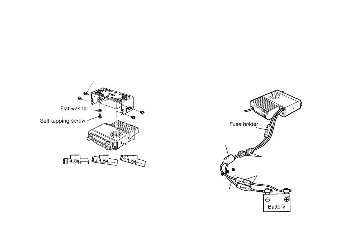
Installation Example
1 Install the mounting bracket using the supplied flat
washers and self-tapping screws. There are 4
washers and 4 screws supplied.
• The bracket can be mounted with the bracket
opening for the transceiver facing down for
underdash mounting, or with the opening facing
up.
• If mounted underdash, the bracket must be
installed so that the 3 screw holes on the edge
of each bracket side are facing forward. This
allows you to mount the transceiver horizontally
or to angle it upward.
• If mounted with the bracket opening facing
upward, position the bracket with the 3 holes
facing forward to angle the transceiver upward.
Position the bracket with the 3 holes facing the
rear if you plan to angle the transceiver
downward. The transceiver can be mounted
horizontally, angled neither up nor down, with the
bracket positioned either way.
Page 11
2 Position the transceiver in the bracket to determine
the best viewing angle.
3 Insert and tighten the supplied hexagon SEMS
screws and washers. There are 2 screws and
2 washers supplied for each side of the bracket.
• Double check that all hardware is tightened to
prevent vehicle vibration from loosening the
bracket or transceiver.
Mounting
bracket
liiSl
SEMS screws <
Stacking plate-'
A
3EE1
DC POWER CABLE CONNECTION
Route the DC power cable supplied with the transceiver,
or an optional DC cable equipped with a noise filter,
directly to the vehicle’s battery terminals using the
shortest path from the transceiver. If using a noise filter,
it should be installed with an insulator to prevent it from
touching metal on the vehicle. It is not recommended to
use the cigarette lighter socket since some cigarette
lighter sockets introduce an unacceptable voltage drop.
Passenger compartment
I'Joise filter supplied
with PG-3B
Power supply connector
........................
,Red ( + ) Fuse holders
Vehicle chassis
Black ( - )
Engine compartment
with 20 A fuses
Double check cable
connections at the
battery to confirm
correct polarities
(Red ^ Positive,
Black ^ Negative).
Page 12

Dismantle fuse holder.
Passenger compartment
To prevent the risk of short circuits, disconnect other
wiring from the negative { —) battery terminal before
connecting the transceiver. Confirm the correct polarity
of the connections before attaching the power cable; red
connects to the positive ( +) terminal, black connects to
the negative ( —) terminal. Use the full length of the
cable without cutting off excess even if the cable is
longer than required. In particular, never remove the
fuse holders from the cable. After completing
transceiver connections to the battery, then reconnect
any wiring removed from the negative terminal.
If the power cable must be routed through a hole in the
vehicle chassis or body, for example in the firewall at the
front of the passenger compartment, use a rubber
grommet to protect the cable from abrasion. The entire
length of the cable must be dressed so it is isolated from
heat and moisture. After the cable is in place, wind heat-
resistant tape around the fuse holder to protect it from
moisture. Tie down the full run of cable.
The vehicle battery must have a nominal rating of 12 V.
Never connect the transceiver to a 24 V battery. Be
sure to use a 12 V vehicle battery that has sufficient
current capacity. If the current to the transceiver is
insufficient, the Display may darken during transmission,
or transmit output power may drop excessively.
Only after completing the installation, connect the
transceiver’s power supply connector to the DC power
cable. Press the connectors firmly together until the
locking tab clicks.
Page 13
Replacing Fuses
ANTENNA CONNECTION
If the fuse blows, determine the cause then correct
the problem. After the problem is resolved, then
replace the fuse. If newly installed fuses continue to
blow, disconnect the power cable and contact your
dealer or nearest Service Center for assistance.
Fuse Location
TM-251A/E
TM-451A/E
Supplied Accessory
Fuse Current Rating
15 A
10 A
20 A
DC Power Cable
CAUTION: Only use fuses of the specified type and rating.
Note: If you use the transceiver for a long period when the
vehicle battery has not been fully charged, or when the engine
has been stopped, the battery may become discharged, and will
not have sufficient reserves to start the vehicle. Avoid using the
transceiver under these conditions.
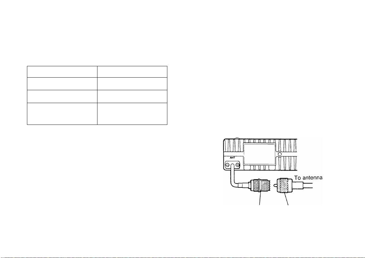
Before operating mobile, you must first install an
efficient, well-tuned antenna. The success of your
mobile installation will depend largely on the type of
antenna and its correct installation. The transceiver can
give excellent results if the antenna system and its
installation is given careful attention.
Your choice of antenna should have a 50 ohm
impedance to match the transceiver input impedance.
Use low-loss coaxial feed line that also has a
characteristic impedance of 50 ohms. Coupling the
antenna to the transceiver via feed lines having an
impedance other than 50 ohms reduces the efficiency of
the antenna system, and can cause interference to
nearby broadcast television receivers, radio receivers,
and other electronic equipment.
ANT connector Feed line connector
CAUTION: Transmitting without first connecting an antenna or other
matched load may damage the transceiver. Always connect the
antenna to the transceiver before transmitting.
Page 14
PREPARATION FOR FIXED STATION OPERATION
The following diagram illustrates how to make
connections to the rear panel of the transceiver.
Connect all cables securely so they will not come loose if
pulled.
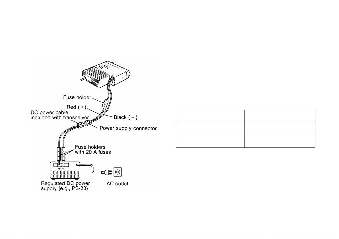
DC POWER SUPPLY CONNECTION
In order to use this transceiver for fixed station operation,
you will need a separate 13.8 V DC power supply that
must be purchased separately. DO NOT directly
connect the transceiver to an AC outlet! Use the
supplied DC power cable to connect the transceiver to a
regulated power supply. Do not substitute a cable with
smaller gauge wires.
The following table lists the current capacity
recommended for power supplies used with each type of
transceiver.
Transceiver Model Power Supply Capacity
TM-251A/E
TM-451A/E
First connect the DC power cable to the regulated DC
power supply and check that polarities are correct
(Red: positive, Black: negative). Then connect the
transceiver’s DC power connector to the connector on
the DC power cable. Press the connectors firmly
together until the locking tab clicks.
11 A or more
10 A or more
Page 15

Note:
► For your transceiver to fully exhibit its performance capabilities,
the following optional power supply is recommended:
PS-33 (20.5 A. 25% duty cycle).
► Before connecting the DC power supply to the transceiver, be
sure to switch the transceiver and the DC power supply off.
► Do not plug the DC power supply Into an AC outlet until you make
all connections.
■ Replacing Fuses
If the fuse blows, determine the cause then correct
the problem. After the problem is resolved, only then
replace the fuse. If newly installed fuses continue to
blow, disconnect the power plug and contact your
dealer or nearest Service Center for assistance.
Fuse Location
TM-251A/E 15 A
TM-451A/E
Supplied Accessory
DC Power Cable
CAUTION: Only use fuses of the specified type and rating.
Fuse Current Rating
10 A
20 A
ANTENNA CONNECTION
The type of the antenna system, consisting of the
antenna, ground, and feed line, will greatly affect the
successful performance of the transceiver. Use a
properly adjusted 50 ohm antenna of good quality
designed for operation at your operating frequency to let
your transceiver perform at its best.
Install low-loss 50 ohm coaxial cable and a first quality
connector for the connection to the transceiver. For
longer feed line runs, especially for operation at UHF
frequencies, you might consider investing in "hardline"
transmission line. Flardline is available in larger
diameters and has much lower loss than coaxial cable.
The lower loss can make a significant difference for
those interested in weak signal operation. In all cases,
match the impedance of the feed line and antenna so
that the SWR is minimum. Generally, an SWR
measurement of 1.5:1 or less is considered satisfactory.
All connections must be clean and tight. Coupling the
antenna to the transceiver via feed line having an
impedance other than 50 ohms reduces the efficiency of
the antenna system. It also can cause interference to
nearby broadcast television receivers, radio receivers,
and other electronic equipment.
CAUTION:
► All fixed stations should be equipped with a lightning arrester to
reduce the risk of fire, electric shock, and transceiver damage.
► Transmitting without first connecting an antenna or other
matched load may damage the transceiver. Always connect the
antenna to the transceiver before transmitting.
Page 16
ACCESSORY CONNECTIONS
EXTERNAL SPEAKER
Use an external speaker with 8 ohms impedance. The
jack accepts a 3.5 mm diameter mono (2-conductor)
plug. Recommended speakers include the SP-50B and
SP-41. Connecting an external speaker automatically
cuts off audio to the internal speaker.
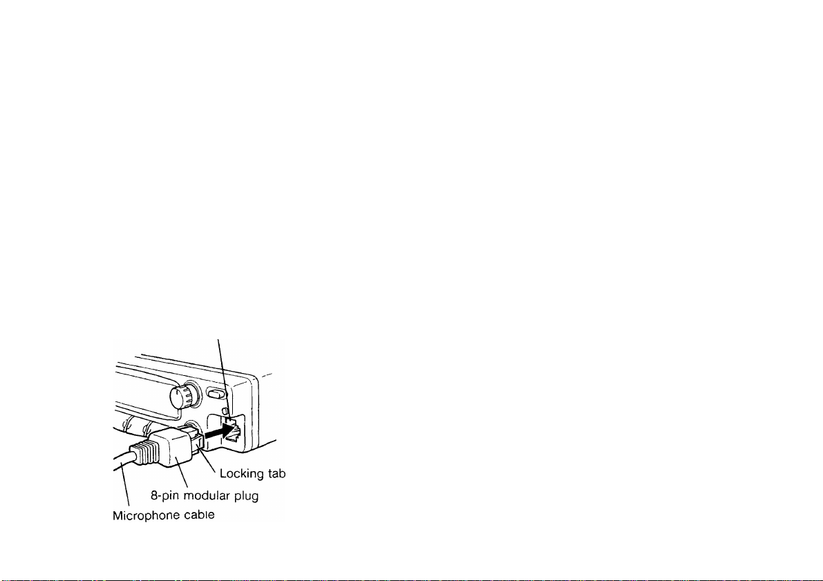
MICROPHONE
To communicate in the voice modes, plug a 600 ohm
microphone equipped with an 8-pin modular connector
into the modular socket on the Front Panel of the
transceiver. Press firmly on the plug until the locking tab
clicks.
Microphone modular socket
PACKET EQUIPMENT
If you intend to use this transceiver for Packet operation,
you will need the following equipment:
• Personal computer with communications software
(Alternatively, a "dumb" terminal capable of sending
ASCII commands)
• TNC (Terminal Node Controller)
• TNC power supply
• RS-232C cable
• 6-pin mini DIN plug (PG-5A)
Refer to the accompanying diagram and the associated
instruction manuals to configure the equipment as
shown. Connect your TNC to the DATA connector on
the transceiver Rear Panel using a cable equipped with a
6-pin mini DIN plug. Do not share a single power supply
between the transceiver and the TNC. Keep as wide a
separation between the transceiver and computer as
practical to reduce noise-pickup by the transceiver.
Page 17
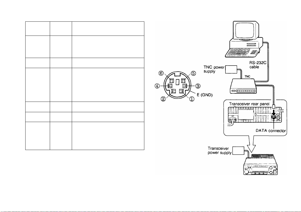
DATA Connector Pinout
Personal computer/dumb terminal
Pin
Number
Pin
Name
Function
Packet data input
1
PKD
• Transmit data from TNC to
transceiver
2
DE Ground for PKD
Packet standby
3
PKS
• TNC can use this pin to
inhibit the transceiver
microphone input while
transmitting packet signals.
4 9600D Detects 9600 bps data.
5
1200D Detects 1200 bps data.
Squelch control output
6
SQC
• Inhibits TNC data transmit
while transceiver squelch is
open.
10
Page 18
GETTING ACQUAINTED
The following sections describe basic functions of the Front Panel controls and buttons, Rear Panel jacks and
connectors, microphone buttons and Display indicators. For full explanations of functions mentioned, refer to the
appropriate section elsewhere in the manual.
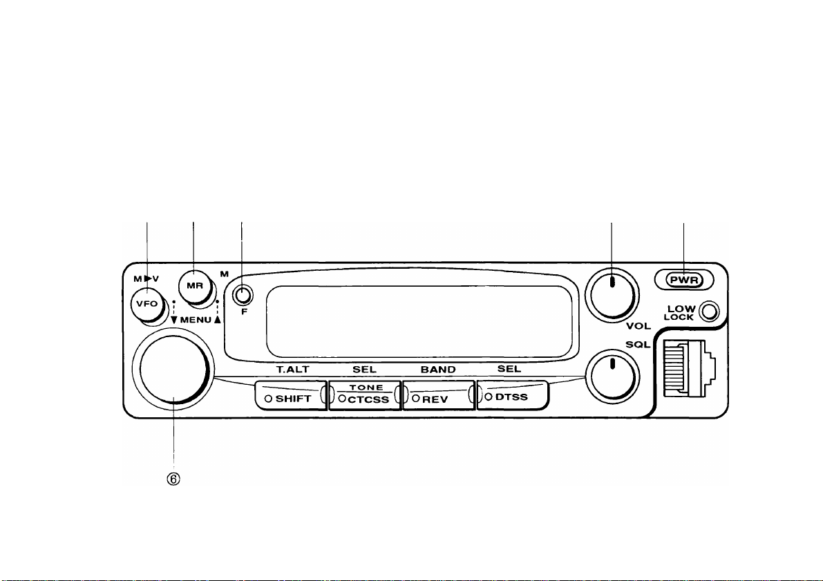
FRONT PANEL
® (D
12
Page 19
YOUR FIRST QSO
If you tend to discard instruction manuals along with the
packaging material....please don’t. The 5 steps below
will get you on the air in your first QSO within minutes to
allow you to experience the exhilaration that comes with
opening a brand new transceiver.
After trying the rig for a while, settle back in your most
comfortable operating chair with this manual and your
favorite drink for an hour or two. The time spent will be
worthwhile.
1 Connect a 13.8 V DC power source to the power
connector, and a suitable antenna to the antenna
connector.
2 Turn the VOL and SQL controls to approximately
9 o’clock.
3 Press [PWR].
• The default frequency appears on the Display.
4 Turn the Tuning control to select a frequency.
5 If accessing a repeater, press [SHIFT] to select a
standard positive transmit offset. Repeat to select a
negative offset.
• Either" +" or" -" appears.
• If a subaudible tone is required to access the
repeater:
a) Press [F], [TONE/CTCSS].
b) Turn the Tuning control to select a Tone
frequency.
c) Press [TONE/CTCSS] to exit from Tone Select.
d) Press [TONE/CTCSS] again to turn ON the
TONE function.
6 When the frequency is clear, press [PTT] and begin
communicating.
• Release [PTT] to receive.
11
Page 20

® VFO button
@ VOL (Volume) control
Provides the following 5 functions:
• VFO mode select {page 32}
• Menu function select (descending order) {page 22}
• VFO Scan {page 59}
• Memory/Call channel transfer to VFO {page 42}
• Partial reset {page 46}
(2)MR (Memory Recall) button
Provides the following 5 functions:
• Memory Recall select {page 41}
• Menu function select (ascending order) {page 22}
• Memory Scan {page 58}
• Memory Write {page 39}
• Full reset {page 46}
(DF (Function) button
Provides the following 3 functions:
• Multiple key function select
• Menu Set-up enter {page 22}
• Menu Set-up exit {page 22}
Adjusts the level of receive audio from the speaker
{page 28}.
(DPWR (Power) switch
Switches the transceiver ON or OFF {page 28}. Also
used in conjunction with other keys to access Menu B
{page 24} or initialize the microprocessor and its
memory {page 46}.
(DTUNING control
Provides the following 6 functions:
• Selects transmit/receive frequencies {page 32} and
frequency limits {pages 33 and 59}.
• Selects memory channels in Memory Recall
{page 41}.
• Selects available choices when configuring Menu
functions {page 22}.
• Selects subaudible Tone frequency {page 52} and
transmit offset {page 50}.
• Selects scan direction {page 58}.
• Selects DTSS/page codes {pages 76 and 79}.
13
Page 21
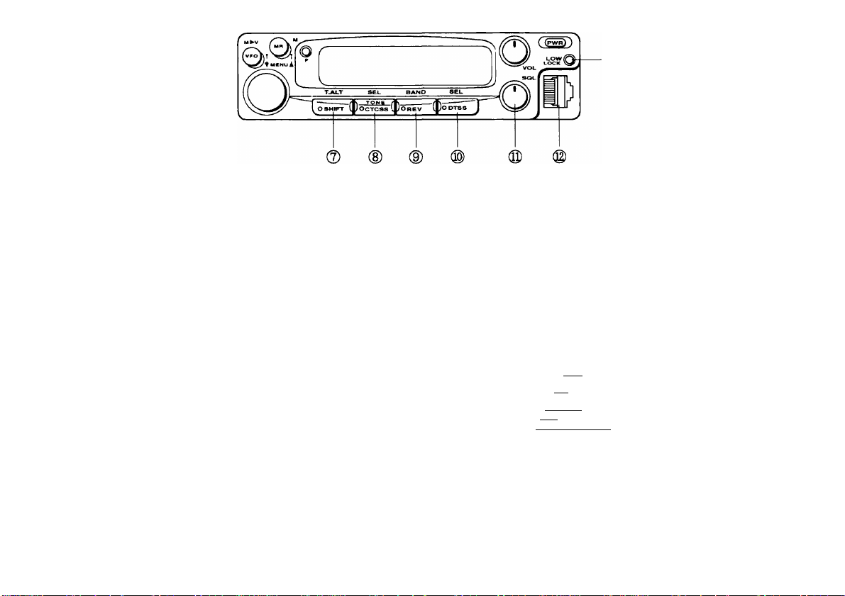
® SHIFT button
Selects the transmit frequency offset with respect to the
receive frequency {page 491. Also toggles Tone Alert
ON or OFF {page 86).
©SQL (Squelch) control
Adjusts the squelch threshold level {page 28). This
allows you to mute speaker output while no stations are
being received.
(DtONE/CTCSS button
Switches Tone and CTCSS ON or OFF {pages 51 and
74). Also used for selecting the subaudible Tone
frequency {page 52}.
d) REV (Reverse) button
Switches the transmit frequency and receive frequency
when operating with a transmit offset or split frequency
{page 51). Also toggles the transceiver between the
Main band or the Sub-band (page 30}.
®DTSS button
Toggles DTSS and Page ON or OFF. Also used for
setting the DTSS code and Page codes {page 75}.
14
©Microphone connector
Insert the 8-pin modular microphone plug until the
locking tab "clicks".
C]
OWN
RD: Oo0f> squelch audio(100 mV/ 10 kfi)
MIC
GND (MIC)
STBY (Pm
GND
DC 8 V. 100 mA max.
UP
(© LOW button
Selects High, Mid, or Low transmit output power. Also
activates Lock {page 62} and memory channel lock-out
{page 58} functions.
Page 22
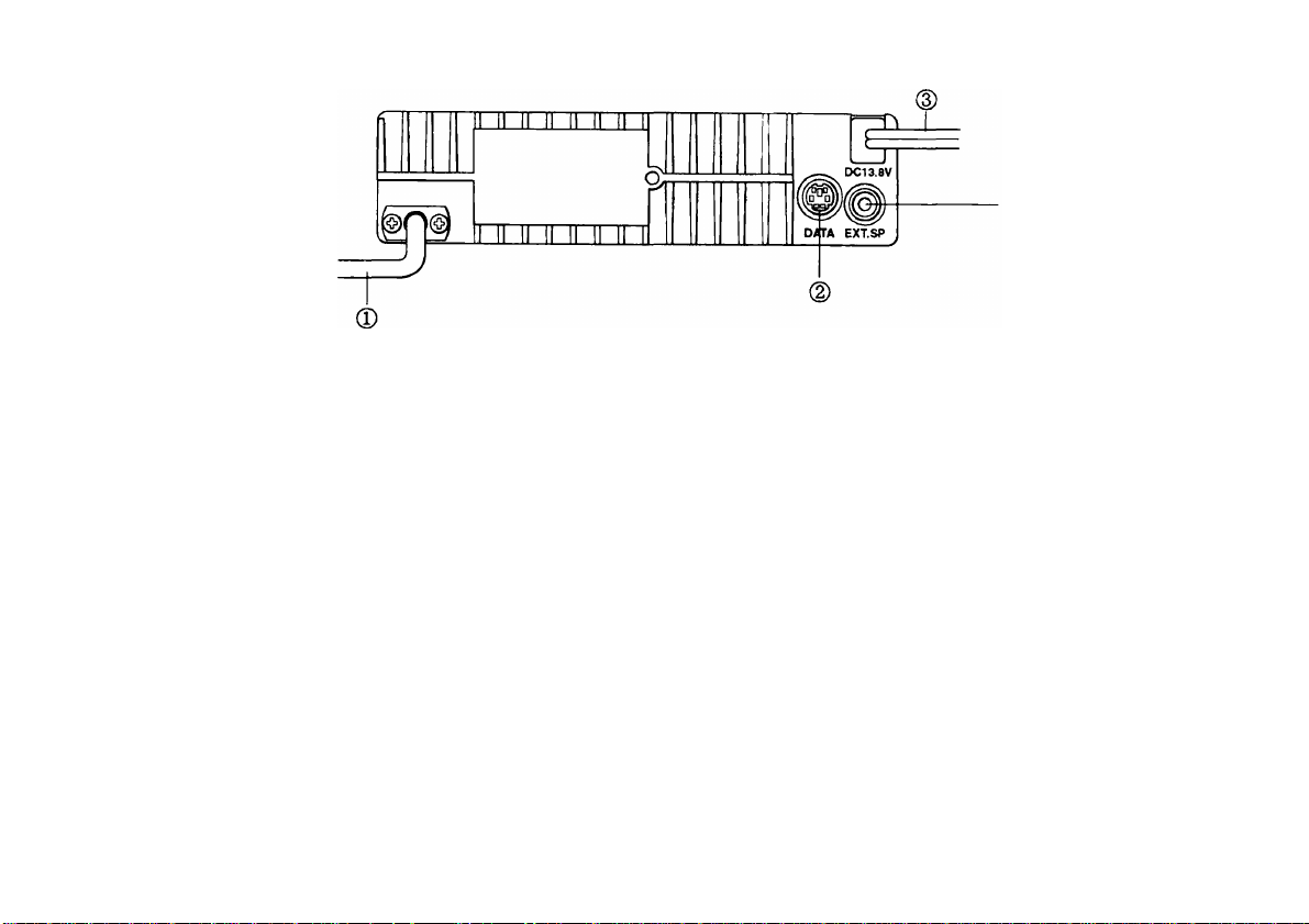
REAR PANEL
1
-d)
® ANT connector
Connect an external antenna designed for operation on
the same band as this transceiver. When making test
transmissions, connect a dummy load in place of the
antenna. The antenna system or load should have an
impedance of 50 ohms. All models accept a male
PL-259 coaxial plug except the TM-451E which accepts
a male Type N plug.
(D DATA connector
Connect a Terminal Node Controller (TNC) for Packet
operation. Accepts a 6-pin mini DIN plug. See page 10
for pinout details.
©Power Input DC 13.8 V connector
Connect a 13.8 V DC power source. Use the supplied
DC power cable.
@ EXT. SP jack
Connect an optional external speaker for clearer audio.
Accepts a 3.5 mm diameter (2-conductor) plug.
15
Page 23
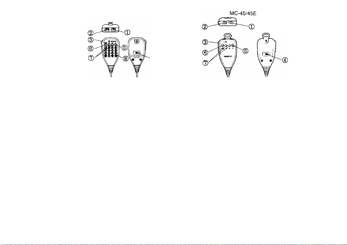
MICROPHONE
MC-45DM/45DME
©
©UP button
(D DWN button
Raises or lowers the VFO frequency, the memory
channel number, the Tone/CTCSS frequency, the
DTSS/Page code, or the Page memory number. Holding
either button down causes the action to be repeated, and
"fuzzy" logic increases the rate of repetition with time.
Also, in Menu Set-up, switches among available menu
selections for each menu function.
® PTT (Push-to-talk) switch
Press to transmit; release to receive. Also, press to exit
Scan and Menu Set-up functions, DTSS/Page code
setting, or Tone/CTCSS frequency setting.
© LOCK switch
Locks all microphone functions except [PTT] and the
DTMF keypad, if equipped.
16
® PF (Programmable Function) key
Activates the Monitor function to open and close the
squelch regardless which squelch system is being used.
The key function can be re-programmed, if desired
{page 70}, On European versions, activates the
1750 Hz tone for repeater access.
(DCALL key, 1750 key
Recalls the Call channel. Pressing for more than
1 second initiates a Call Scan. The Call function can be
re-programmed, if desired (page 70}. On European
versions, sends a 1750 Hz tone for repeater access.
©VFO key, MR key
Identical to the Front Panel functions of the same name.
Both functions can be re-programmed, if desired
{page 70}.
(D DTMF keypad (some versions only)
The 16-key keypad is used to transmit DTMF tones.
Page 24

DISPLAY
® (D (D ®
LOCK\+V+U :L0W
....
^nnO O O
DUP/
CO
S»RF 13579 OVER
©LOCK
Indicates the Lock function is ON; most Front Panel and
microphone buttons and keys are locked {page 62}.
Indicates AM receive mode is ON. Blinks while
accessing Menu A, AM/FM Mode {page 23}. AM/FM
mode is available only on some versions of the
TM- 251A/E {page 31}.
(D +v +u
Indicates the 144 MHz Sub-band (" +V") or 430/440
MHz Sub-band (" +U") is selected {page 30}.
MID i REV/—\— +;■< O O O O O O O:
^ V# Ct O 0.0 O 0.0;
APO
-----------
CTCSS
PAG
DTSS
. w* -iSEEP
;U
‘U m U ^ T O T
DIM
l.fSTEP TONE
©LOW, MID
Indicates Low or Mid transmit output power is selected
(page 37). When "LOW" or "MID" are not visible, High
output power is selected.
©REV
Indicates the Reverse function is ON {page 51}.
Transmit and receive frequencies are reversed.
(DQ
Appears when [F] is pressed. Indicates that alternate
functions of multiple-function buttons can be accessed
now.
17
Page 25

® (D (D ® (S)
L0CK:+V+U :L0W mid:
r^!3|Q[i0i
Wi n O O U C<Wg2
DUP/
CO
i¿»cttfiw nilfcva I
@ - - +
SARF
Indicates the transmit frequency is offset (different) from
the receive frequency {page 49}. The symbol displayed
indicates the direction that the transmit frequency is
offset from the receive frequency. Also indicates a splitfrequency memory channel is selected (page 41}. "
blinks while Menu A, Transmit Offset is selected
{page 23}.
Indicates Tone Alert is ON {page 86}. When using Tone
Alert, blinks after receipt of a signal. Also blinks while
Menu A, Tone Alert Alarm Tone is selected
{page 23}.
REV/- r.:^ilk
O it ó Q O O:
U $I,U Q U,U:
nii / APÓ
DIM
------
' PAG
,«-«BEEP DTSS
nil
OVER
^ W M^TEP TONE
3:LI«S.fWTOT CTCss
Indicates the selected memory channel is locked-out
{page 58}.
MENU
Blinks while accessing Menu A {page 23}. Remains ON
while accessing Menu B {page 24}.
® DIM
Blinks when selecting the level of Display illumination in
Menu A, Display Brightness {page 23}.
This indicator is not currently used.
18
Page 26

LOCK: +V +U : LOW MID! REV/
--------------------
r«
Wm O O O O Wi
DUP.ij
ItldO.Cl.O OMB
CO !
Ufcy»lM IslIkIM
■ ■ ■ ■ ■ ■ ■ ■ ■ llll ElZi 'V P ^TEP TON E
SARF
1 3 5 7 9 OVER EUD ;!.l« £ff«TOT CTCSS
+/.^ O Q O O O O O:
.{mm Apo
★ DIM PAG
-¿ii-BEEP DTSS
DUP
Indicates Full Duplex mode is ON {page 91}. Blinks
while accessing Menu A, Full Duplex {page 23}.
®CO
Indicates Carrier-operated Scan Resume is ON
{page 57}. When not visible, Time-operated Scan
Resume is in effect. Blinks while accessing Menu A,
Scan Resume {page 23}.
Indicates S-meter squelch is ON {page 29}. Blinks while
accessing Menu A, S-meter Squelch {page 23}.
® liilkUi
Indicates the squelch is open due to a receive signal or
noise that is greater in strength than the noise squelch
threshold level {page 28}. Also appears when the noise
squelch is set to minimum by turning the SQL control
fully counterclockwise. If using either CTCSS or DTSS,
indicates the squelch is open due to a received signal
that contains a CTCSS tone or DTSS code that matches
the tone or code programmed in your transceiver.
® ISSOXlO uM
n tip
Displays the transmit/receive frequency, frequency step
{page 35}, and Tone frequency {page 52}. Also
displays the available selections when using Menu
Set-up {page 22}. The decimal point blinks while the
transceiver is scanning {page 59}.
19
Page 27
In Receive, acts as an S-meter to indicate the signal
strength of received signals. In Transmit, acts as an RF
power meter to indicate the relative transmit output
power {page 37}. Full scale represents High transmit
power.
Indicates the transceiver is in Transmit mode with a
transmit frequency that is within the transmit band.
:0 O ':
Displays the currently selected memory channel number
{page 41} or Menu B number {page 24}. The dots
beside the memory channel numbers are used only by
the ME-1 Expansion Unit. The right dot appears when
the 100s digit of the channel number is 1 (memory
channels 100-199). The left dot appears when the 100s
digit of the channel number is 2 (memory channel 200).
20
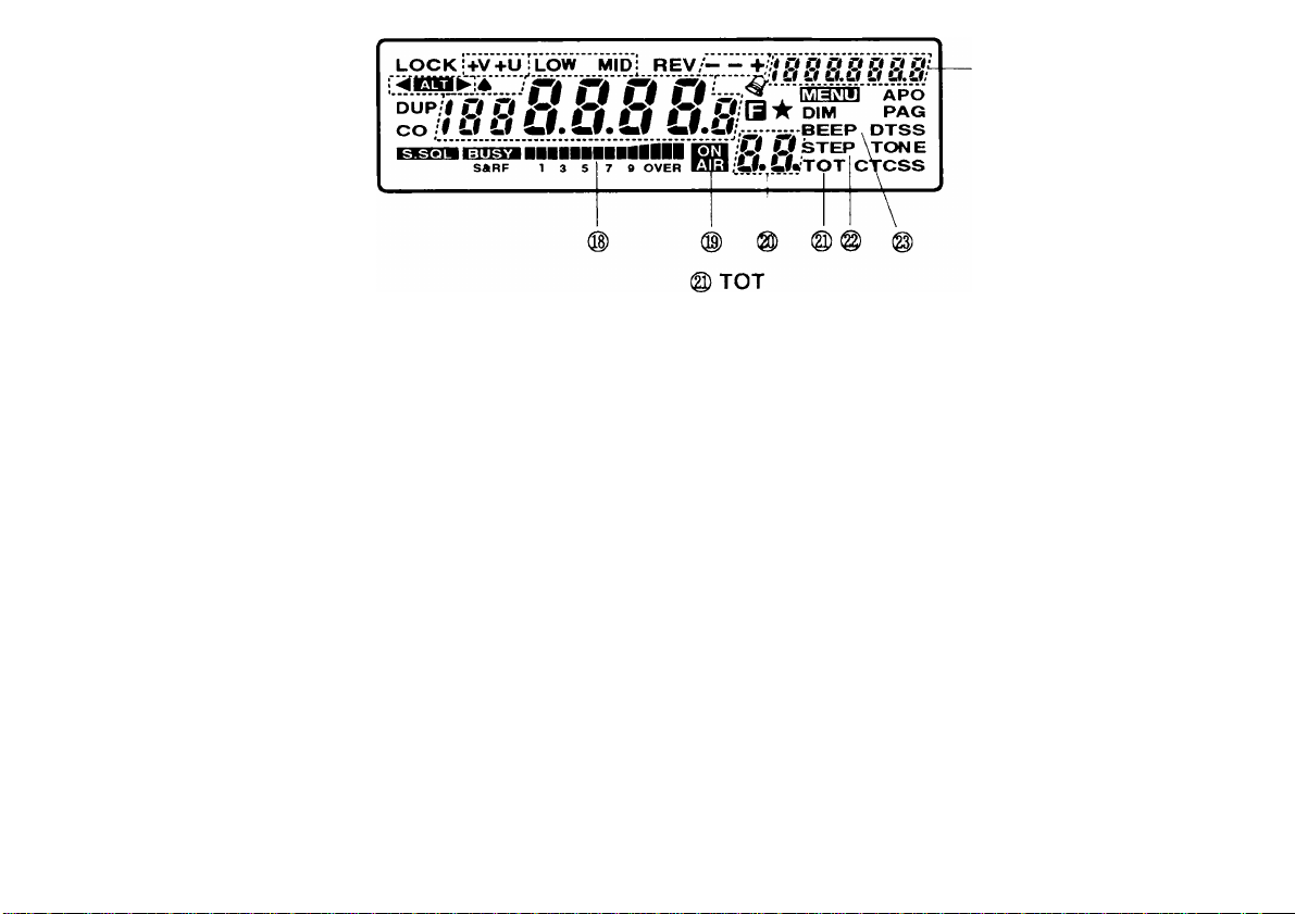
Indicates the Time-out Timer is ON {page 38}. Blinks
while accessing Menu A, Time-Out Timer {page 23}.
® STEP
Blinks while accessing Menu A, Frequency Step
{page 23}.
@ BEEP
Blinks while accessing Menu A, Confirmation Beep
{page 23}.
Acts as a Sub-display to show receive frequency. Tone
frequency, etc.
Page 28

LOCKiJfV+u’rLOw 'WDi REV/-- 0
DUP
CO /
UM»T isiiiaM I
---
------------------------------
n 'U O O U'nip
SARF
y tf.tf V !J^U:
II iJsTEP TONE
..-—-—-BEEP DTSS
ER ESo
:Lh LUtot
^.\ssm APo-
Hw DIM PAG
ctcss
© APO
Indicates Automatic Power Off is ON {page 63}. Blinks
while accessing Menu A, Automatic Power Off
(page 23}.
@ PAG
Indicates Page is ON (page 79}.
@ DTSS
Indicates the Dual Tone Squelch System is ON
(page 75}.
@TONE
Indicates the subaudible Tone encoder is ON {page 52}.
(i) CTCSS
Indicates the Continuous Tone Coded Squelch System is
ON when the CTCSS option (TSU-8) is installed
{page 74}.
21
Page 29

MENU SET-UP
MENU DESCRIPTION
Many functions on this transceiver are selected or
configured via software-controlled menus instead of
physical controls on the transceiver. Once familiar with
the Menu system, you will appreciate the versatility it
offers. No longer is the number and complexity of
features restricted by the physical size of transceiver.
The Menus are identified as Menu A and Menu B.
Menu A is used to access functions that are frequently
changed while Menu B is used for less frequently
changed functions.
MENU A ACCESS
Anytime that you want to change a function that is
controlled by Menu A, use the following procedure:
1 Press [F] (1 s) to enter Menu A.
• "MENU" begins blinking and the menu selected last
appears.
2 Select the desired menu function by pressing either
[MR] or [VFO].
• Press [VFO] to cycle through functions in a
downward direction on the chart.
• Press [MR] to cycle through functions in an upward
direction on the chart.
Microphone [MR] or [VFO] may be used if more
convenient.
Select the desired menu selection by turning the
Tuning control or by pressing microphone [UP] or
[OWN].
When selecting from a group of numeric menu
selections, turning the Tuning control clockwise or
pressing microphone [UP] selects in ascending
order, and turning the Tuning control
counterclockwise or pressing microphone [OWN]
selects in descending order.
4 After selecting the desired menu selection, press
[SHIFT] or [TONE/CTCSS] or [REV] or [DTSS] to
exit Menu A.
Note: The Automatic Power Off timer stops counting while you are
in Menu Set-up.
22
Page 30

MENU A CONFIGURATION
Menu
Label
DIM Display Brightness
BEEP
STEP
TOT
APO Automatic Power Off
DUP
CO Scan Resume
S.SQL S-meter Squelch
+ —
A
^ TM-251A (U.S.A. and Canada): 5 kHz
2 TM-251A/E: 600 kHz. TM-451A: 5 MHz, TM-451E; 1.6 MHz
^ Only on Main Band of TM-251A/E with expanded receive coverage outside the Amateur bands.
• 5 illumination levels (d1: brightest)
Confirmation Beep
Frequency Step Size
Time-Out Timer OFF/3/5/10/20/30
Full Duplex
Transmit Offset (Shift)
Tone Alert Alarm Tone Bel1/Bel2/Bel3
Display Mode during CTCSS, DTSS, or Page
AM/FM Mode^
Description
Selections
OFF/d4/d3/d2/d1 d2
OFF/ON
12.5kHz/25kHz/5kHz/
10kHz/15kHz/20kHz
minutes
OFF/60/120/180
minutes
OFF/ON
TO/CO
OFF/ON
d, 5 kHz to 40 MHz
OFF/Sub1/Sub2
A/F
TM-251A/E: 12.5 kHz’
TM-451A/E: 25 kHz
FM (AM: 118 to 136 MHz)
Default
ON
OFF
OFF
OFF
TO 57
OFF
d^
Bell 87
OFF
Page
64
64
35
38
63
91
29
50
65
31
23
Page 31

MENU B ACCESS
Anytime that you want to change a function that is
controlled by Menu B, use the following procedure:
1 Press [REV] + POWER ON to enter Menu B.
• The menu and menu number selected last appears.
2 Select the desired menu function by pressing either
[MR] or [VFO].
• Press [MR] to increment Menu No., and [VFO] to
decrement Menu No.
• Microphone [MR] or [VFO] may be used if more
convenient.
MENU B CONFIGURATION
Select the desired menu selection by turning the
Tuning control or by pressing microphone [UP] or
[OWN].
• When selecting from a group of numeric menu
selections, turning the Tuning control clockwise or
pressing microphone [UP] selects in ascending
order, and turning the Tuning control
counterclockwise or microphone [DWN] selects in
descending order.
After selecting the desired menu selection, press
[SHIFT] or [TONE/CTCSS] or [REV] or [DTSS] to
exit Menu B.
Menu
No
Remote Control Mode OFF/ON OFF
50
Automatic Page Cancel
51
52 Open Page OFF/ON
DTSS/Page Transmit Delay Time (offset/split only)
53
54 Transmit Hold for 1750 Hz Tone
• TM-251E/TM-451E only
Transmit Inhibit
55
Frequency Change during Memory Recall
56
57 DATA Connector Baud Rate
Description
350ms/550ms 350 ms
24
Selections Defauit
OFF/ON
OFF/ON
OFF/ON
OFF/ON
1200/9600
OFF
OFF
OFF
OFF
OFF
1200
Page
67
84
85
76,83
53
38
41
93
Page 32

Menu
No
58
Microphone Connector Receive Audio
Description
• Audio available from RD terminal while squelch is open.
Channel Display
59
• Frequency Display (OFF) or Channel Number Display (ON)
Programmable Band Scan (Lower Limit)
60
Programmable Band Scan (Upper Limit)
61
62 Programmable VFO Tuning (Lower Limit)
Programmable VFO Tuning (Upper Limit)
63
64
Squelch Hang Time Select
DTMF Memory Store
65
Record Timer Select
66
67
Record Mode
• Continuous (1) or Single (2)
68-70 Unsupported Functions
71 Page Answer-back
72 Message Playback Control via DTSS
DTSS Code Select for Message Playback
73
Selections Default
OFF/ON
OFF/ON
Receive
ON
OFF
—
Frequencies
Receive
—
Frequencies
Receive
Frequencies
Lowest
Receive
Frequency
Receive
Frequencies
Highest
Receive
Frequency
OFF/125/250/500 OFF
OFF/P —
8 sec/16 sec
1/2
-
OFF/ON
OFF/ON
000-999
OFF
8 sec
1
OFF
OFF
919
Page
71
45
59
59
33
33
29
54
88
89
-
83
77
78
25
Page 33

CONFIRMATION BEFORE OPERATION
Before proceeding, run through the following checklist to
double check that your transceiver is ready to operate;
REAR PANEL
ANT (Antenna)
• Is the correct antenna actually connected?
• Is a lightning protector installed for a fixed station?
• Are interconnecting coaxial cables between the
transceiver, accessory station equipment and the
antenna connected?
• Are all cable connectors well-installed (including no
cold solder joints?) and screwed tight?
• Are coax switches set for the correct antenna?
CAUTION: DO NOT transmit without connecting an antenna or
dummy load to the ANT connector. The transceiver can fail.
DC 13.8 V (DC Power Cable)
• Is the power cable connected and locked in place?
(Do not turn on the transceiver or DC power supply
yet.)
DATA Connector
• Is a TNG connected correctly for Packet operation?
26
Page 34

FRONT PANEL
Controls
• Are they preset as shown in the diagram?
Microphone
• Is a recommended microphone installed?
27
Page 35

RECEIVING
SWITCHING POWER ON/OFF
Switch ON the DC power supply, then press [PWR] to
switch ON the transceiver.
• If operating mobile, simply press [PWR] on the
transceiver.
• After the on message, the frequency and
possibly other indicators appear on the Display.
To switch OFF the transceiver, press [PWR] again.
In a fixed installation, after the transceiver has been
switched ON, it can then be switched OFF or ON by
using only the power switch on the DC power supply.
VOLUME ADJUST
Turn the VOL control clockwise to increase the audio
level, and counterclockwise to decrease the level.
SQUELCH ADJUST
The purpose of squelch is to silence audio output from
the speaker when no signals are present. When squelch
is set correctly, you will hear sound only while a station
is actually being received. At this time, "BUSY" appears
on the Display.
■ Noise Squelch
Turn the SQL control clockwise to just eliminate the
background noise when no signal is present.
The point at which ambient noise on a frequency just
disappears, called the squelch threshold, depends on
the frequency. Setting the squelch threshold too high
causes squelch to remain closed while a weak signal
is present. The station will not be heard. You may
mistakenly think your transceiver’s receive sensitivity
is low or you have an audio problem.* Setting the
threshold too low allows noise to be heard between
transmissions from other stations.
28
Page 36

S-Meter Squelch
SQUELCH HANG TIME
By activating S-meter Squelch, you can set the
squelch threshold so the squelch does not open until
a signal with the same or greater strength than the Smeter setting is received.
1 Press [F] (1 s) to enter Menu A.
2 Select "S.SQL" {page 22}.
• The current S-meter Squelch status appears.
t tj tj O
\ \ 1 / /
/ / M \ “«f
n c c
1 S • 7 • OVCR
/ / n \
3 Select a squelch status.
• OFF: Disables S-meter Squelch.
• ON: Enables S-meter Squelch.
• Default: OFF
4 Exit Menu A.
• "S.SQL" remains ON.
5 After switching S-meter Squelch ON, adjust the
SQL control to set the S-meter for the minimum
signal strength that you want to open the squelch.
When using S-meter Squelch, you may want to adjust
the Hang Time (time for the squelch to close after the
received carrier drops).
1 Press [REV] + POWER ON to enter Menu B.
2 Select Menu No. 64 (page 24}.
• The current Hang Time value appears.
3 Select a value.
• The available selections are OFF, 125, 250,
500 ms.
• Default: OFF.
4 Exit Menu B.
29
Page 37

BAND SELECT
The transceiver is equipped with a Main Band for both
transmitting and receiving, plus a Sub-band for receiving
only. When the Sub-band is selected, [PTT] is disabled,
although [TONE/CTCSS] and [REV] are still functional.
Full Duplex communication is possible by taking
advantage of the receive capability of the Sub-band.
See page 91 for more information on Full Duplex
operating.
Version
Canada
U.S.A.
Europe
General
Main Band
144 MHz ’
144 MHz ^
TM-251
Sub-Band
440 MHz 2
430 MHz
’ Expanded receive coverage: 118 to 174 MHz
^ Expanded receive coverage: 300 to 470 MHz
^ Some versions include expanded receive coverage:
118 to 174 MHz
“ Some versions include expanded receive coverage:
300 to 470 MHz
® Expanded receive coverage: 136 to 174 MHz
® Some versions include expanded receive coverage from
136 to 174 MHz. Some versions include an expansion band
that covers 800 to 1000 MHz.
30
Version
Canada
U.S.A.
Europe
General
Main Band
440 MHz 2
430 MHz “
TM-451
Sub-Band
144 MHz 5
144 MHz ®
Page 38

Select the Main Band or Sub-band by pressing
[F], [REV].
• When the Sub-band is selected, " + U" or" + V"
appears as a reminder that the UHF or the VHF Sub
band is currently selected.
• After switching bands, the frequency used last on the
new band and the frequency step stored in Menu A
for the new band are selected automatically.
• Each time the above button combination is entered,
the transceiver toggles between the Main Band and
Sub-band.
Note: The 800 MHz expansion band on European and General
versions is selected in the same way as the Sub-band by pressing
[FJ, [REV].
■ Selecting AM/FM Mode (TM-251A/E only)
The U.S.A. and Canada versions of TM-251A, plus
some versions of TM-251A (General) and TM-251E
are able to receive AM and FM modes on the Main
Band. The AM mode is selected automatically when
any frequency in the range 118.000 to 135.995 MHz
(AIR band) is chosen. Outside this range, the default
is FM, but AM can be selected manually via Menu A.
Changing bands after manually selecting AM or FM
mode causes the default mode to be restored
automatically.
1 Select the Main Band by pressing [F], [REV].
• AM/FM selection is only possible on the Main
Band.
2 Press [F] (1 s) to enter Menu A.
3 Select "Spade" {page 22}.
• "Spade" begins blinking and the current AM/FM
selection appears.
-'к
MRF 1 »
7 t OVER
О
ч
1гао8й
—
___________
/ /1 \ \
Select a mode.
• The available selections are AM or FM.
• Default : 118.000 to 135.995 MHz : AM
All other frequencies : FM
Exit Menu A.
• "Spade" remains ON if the AM mode was
selected.
• When AM is selected outside the AIR band,
"Spade" disappears while transmitting since FM
is used for transmissions.
Г
31
Page 39

VFO MODE
SELECTING FREQUENCIES
The VFO mode allows you to select operating
frequencies by using the Tuning control or the
microphone as explained under "SELECTING
FREQUENCIES" below.
Press [VFO] to select VFO mode.
• The currently selected frequency appears.
• If already in VFO mode, there is no change.
VFO mode must be selected when using the following
functions:
Select VFO
mode to use:
Programmable
Band Scan Limit
Select
Page
Ref.
59
Select VFO
mode to use:
Programmable
VFO Limit
Select
Page
Ref.
33
■ Tuning Control
Using the Tuning control is convenient when you are
within easy reach of the transceiver Front Panel, and
the frequencies to be selected lie near the current
frequency. The "fuzzy logic" design temporarily
increases the frequency step size as the Tuning
control is turned more rapidly.
Press [VFO] to select VFO mode.
Select your desired band by pressing [F], [REV].
Turn the Tuning control to select a receive
frequency.
Clockwise rotation increases the frequency one
frequency step at a time.
Counterclockwise rotation decreases the
frequency one frequency step at a time.
If you cannot select a particular receive frequency, the
frequency step size needs to be changed. See
"FREQUENCY STEP SIZE" {page 35} for further
information.
Note: Frequencies can also be selected via the microphone
keypad. See "KEYPAD DIRECT ENTRY" {page 7i}.
32
Page 40

Programmable VFO
Select Menu B, No. 62.
You may want to set limits for the minimum and
maximum frequencies that are selectable with the
Tuning control, for example, to keep your operating
within the frequencies set aside by band plans for FM
operation. The limits can be set or modified at any
time, and are configurable for each band on the
transceiver.
1 Press [VFO] to select VFO mode.
2 Select the band on which you want to set the VFO
limits by pressing [F], [REV].
3 Press [REV]+ POWER ON to enter Menu B, then
select Menu No. 63 {page 24}.
• The current upper limit appears.
• The default is the maximum frequency that can
be selected on your version of transceiver.
4 Turn the Tuning control, or press microphone [UP]
or [OWN], to select the desired upper limit.
• The 10 kHz and lower digits are fixed according
to the frequency step currently selected in
Menu A:
5, 10, 15, 20 kHz: 95
12.5,25 kHz: 87.5
• The upper limit must be either 87.5 kHz or
95 kHz higher than the lower limit depending on
the current frequency step.
• The current lower limit appears.
• The default is the minimum frequency that can
be selected on your version of transceiver.
Turn the Tuning control, or press microphone [UP]
or [DWN], to select the desired lower limit.
• The 10 kHz and lower digits are set to 0.
Exit Menu B.
Note:
The upper limit is set first above; however, either lower or upper
►
limit may be set first provided the upper limit is placed in
Menu B. No. 63 and the lower limit is placed in Menu B, No. 62.
To reset the limits to their default values, you can do a Partial or
Full Reset (page 46}, or manually set the limits to the maximum
and minimum frequencies for your version of transceiver.
33
Page 41

Microphone [UP]/[DWN] Buttons
Using microphone [UP] or [DWN] for frequency
selection is useful when mobiling or anytime you are
not immediately in front of the transceiver.
Press [UP] or [DWN] once to change the receive
frequency by one frequency step in the direction
indicated by the button.
• Pressing and holding either button causes the
frequency to step repeatedly in one direction until
the button is released.
34
Page 42

FREQUENCY STEP SIZE
4 Select "STEP" {page 22}.
Choosing the correct step size when operating is
essential in order to select your exact receive frequency
with the Tuning control or microphone [UP]/[DWN]. The
best step size is the largest step that will still allow you to
select all frequencies on which you plan to operate.
Using the best step size reduces the time required to
select new frequencies; operating becomes easier.
Defaults (kHz)
Version
Canada
U.S.A.
Europe
General
The 800 MHz expansion band is on some European and
General versions.
1 Press [VFO] to select VFO mode.
• The step size can only be changed in VFO mode.
2 Select the band on which you want to set the
frequency step by pressing [F], [REV].
TM-251 TM-451
Main Sub
5 25 25 5
12.5 25 25 12.5
Main
Sub/Exp.'
• "STEP" begins blinking and the current frequency
step appears.
5 Select a step size.
• The available steps are as follows:
5 kHz
TM-251A/E
TM-451A^E
TM-451A/E'
(800 MHz only)
’ Some European and General versions only.
6 Exit Menu A.
X
25 kHz
12.5 kHz ◄
10 kHz
12.5 kHz
------
► 25 kHz
15 kHz
20 kHz
:
3 Press [F] (1 s) to enter Menu A.
35
Page 43

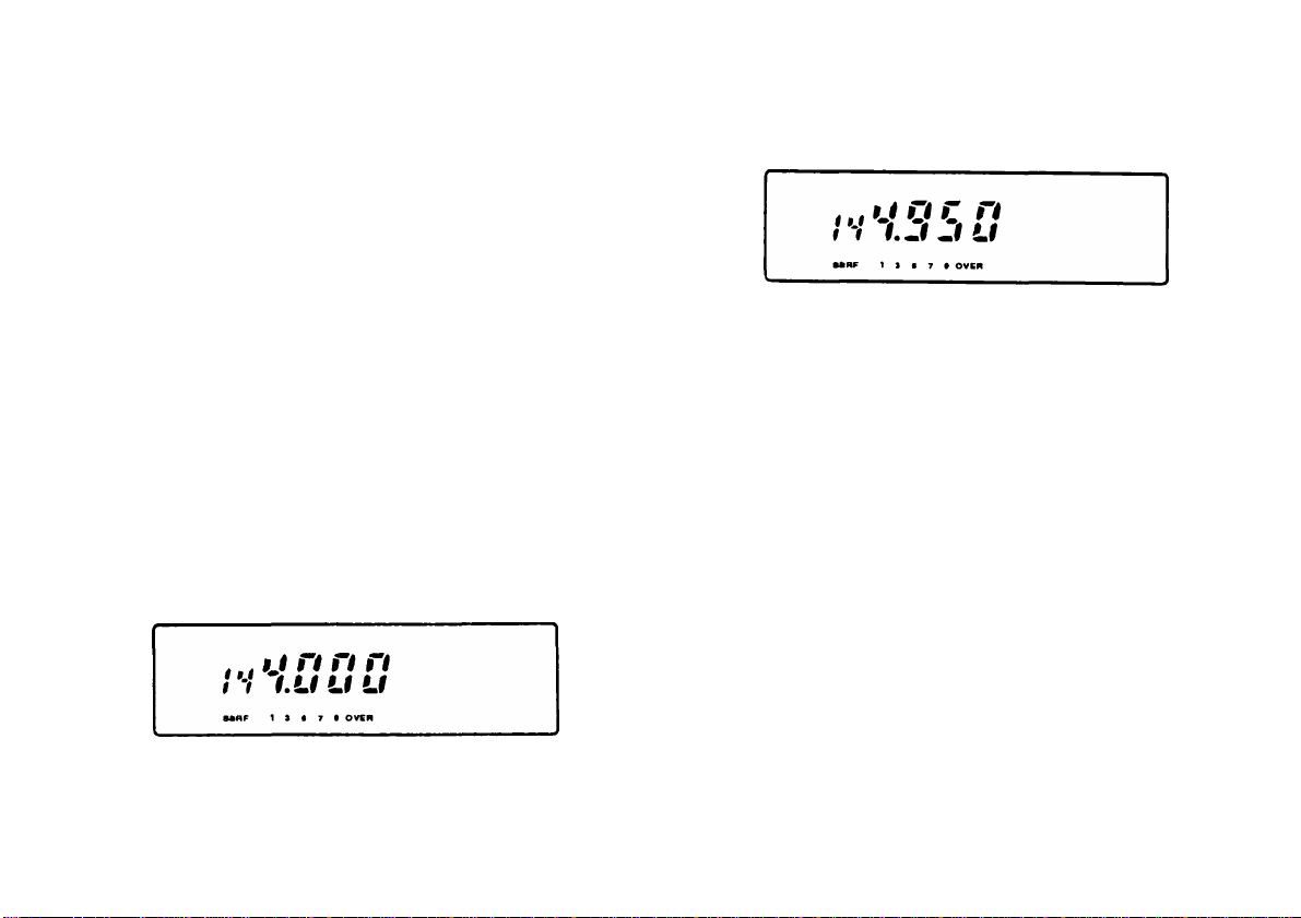
Changes In Displayed Frequencies
Changing between step sizes may result in a change
of the displayed frequency. When a change occurs,
and by how much, is shown in the accompanying
charts. This change also affects upper and lower
frequency limits selected for the Programmable Band
Scan function {page 59} and the transmit offset
selection in Menu A (page 23}.
For example, assume 144.995 MHz is displayed with a
20 kHz step size selected. Changing to a 25 kHz step
size alters the displayed frequency to 144.975 MHz.
5, 10, 15 or 20 kHz 12.5 or 25 kHz
Step Size Step Size
Displayed Frequency
(10 kHz/1 kHz)
00, 05, 10, 15
20, 25, 30, 35
40, 45, 50, 55 50
60, 65, 70, 75, 80, 85, 90, 95
Displayed Frequency
(10 kHz/1 kHz)
00
25
75
12.5 or 25 kHz ^ 5, 10, 15 or 20 kHz
Step Size Step Size
Displayed Frequency
(10 kHz/ 1 kHz/500 Hz)
00
12.5
25
37.5 30
50
62.5
75
87.5
Displayed Frequency
(10 kHz/1 kHz)
00
10
20
50
60
70
80
36
Page 44

TRANSMITTING
MICROPHONE PTT
When ready to begin transmitting, press and hold [PTT]
and speak in a normal tone of voice. Speaking too close
to the microphone, or too loudly, may increase distortion
and reduce intelligibility of your signal at the receiving
station.
SELECTING OUTPUT POWER
It’s wise, and required by law, to select the lowest power
that allows reliable communication. If operating from
battery power, lower transmit power will give you more
operating time before a charge is necessary. Reducing
power lowers the risk of interfering with others on the
band too. It is possible to change output power while
transmitting.
Press [LOW] to select the transmit power you require.
• Default: High power (no indicator visible)
• Each press of [LOW] changes the power as follows:
High
Model
TM-261 50 W Approx. 10 W Approx. 5 W
TM-451
Mid ("MID"'
High
35 W Approx. 10 W Approx. 5 W
■> Low ("LOW")
Mid Low
37
Page 45

TIME-OUT TIMER (TOT)
It is sometimes necessary or desirable to restrict a single
transmission to a specific maximum time. This feature
can be useful when accessing repeaters to prevent
repeater time-outs, or when particularly trying to
conserve battery power. Activate TOT anytime you
wish to limit your transmit time.
1 Press [F] (1 s) to enter Menu A.
2 Select "TOT" {page 22}.
INHIBITING TRANSMIT
The transmit function can be disabled to prevent
unauthorized individuals from transmitting, or to eliminate
the risk of yourself accidentally transmitting.
1 Press [REV] + POWER ON to enter Menu B.
2 Select Menu No. 55 {page 24}.
• The current status of Transmit Inhibit appears.
• Default: OFF
• "TOT" begins blinking and the current TOT
selection appears.
3 Select a timer value.
• The available selections are OFF, 3, 5, 10, 20, and
30 minutes.
• Default: OFF
4 Exit Menu A.
• "TOT" remains ON.
When TOT times out, the transceiver automatically
returns to Receive. To resume transmitting, release and
then press [PTT] again.
38
<»,«
Ki о К ft
1 1
C к
Л Л
Pji j.'4ll
n c c
и • *
1 > ■ 7 • OVER
3 Select a status.
• OFF: Can transmit.
• ON: Cannot transmit.
4 Exit Menu B.
If [PTT] is pressed while Transmit Inhibit is ON, your
transceiver beeps and will not transmit.
Page 46

MEMORY CHANNELS
A total of 40 memory channels (1 to 40) are available for
storing frequencies and related data. Each memory
channel can be used either as a simplex channel or split
channel for storing any frequency or frequency pair that
can be selected on the transceiver. Alternatively, a
standard or non-standard frequency offset and offset
direction required for using repeaters can be stored.
Refer to "OPERATING THROUGH REPEATERS"
{page 48}.
The data listed below can be stored in each memory
channel:
Parameter
RX frequency
TX frequency YES
Tone (CTCSS) frequency YES YES
Tone or CTCSS status YES
Frequency step YES YES
Shift status, REV status YES
DTSS code, DTSS status YES YES
YES: Can be stored in memory.
N/A: Not applicable
Note: The total number of memory channels can be expanded to
200 by installing the ME-i Expansion Unit option.
Simplex
Channel
YES
Split
Channel
YES
YES
N/A
STORING DATA IN MEMORY
There are 2 methods of storing transmit/receive
frequencies and associated data in memory channels
depending on the relationship of the transmit and receive
frequencies:
• Simplex memory channels:
RX frequency = TX frequency
• Split memory channels:
RX frequency ^ TX frequency
■ Simplex Memory Channels
1 Select the desired frequency and associated data
(Tone, CTCSS, DTSS, etc.) using VFO mode.
Memory Recall or the Call channel.
2 Press [F] to select Memory Storage.
• "F" and a memory channel number appear.
39
Page 47

3 Turn the Tuning control, or press microphone [UP]
or [DWN], to select the desired memory channel.
4 Press [MR].
The selected frequency and associated data are
stored in the memory channel. A transmit
frequency from a split memory channel or split
Call channel is not stored.
• If the memory channel selected in the previous
step already contained data, the new data
overwrites the previous data.
• The previous mode is restored.
Split Memory Channels
1
Select the desired receive frequency and
associated data (Tone, CTCSS, DTSS, etc.) using
VFO mode. Memory Recall or the Call channel.
Press [F] to select Memory Storage.
♦ "F" and a memory channel number appear.
Turn the Tuning control, or press microphone [UP]
or [DWN], to select the desired memory channel.
Press [MR](1 s).
• ” - +" appears.
kJ O
I‘-I XO LI LI
\ г % 1 9 oven
Turn the Tuning control, or press microphone [UP]
or [DWN], to select the desired transmit frequency
Press [MR].
• The selected transmit frequency is stored in the
memory channel, and the previous mode is
restored.
Associated data selected in Step 1 such as Tom
status/frequency, the frequency step, and DTSS
status/code are not altered by this step.
However, Transmit Offset status and Reverse
status are erased.
40
Page 48

RECALLING MEMORY CHANNELS
Temporary Frequency Changes
■ Selecting Channels Sequentially
This method allows you to select, in numerical order
by channel number, all memory channels containing
data.
1 Press [MR],
• The memory channel used last is recalled.
2 Turn the Tuning control, or press microphone [UP]
or [DWN], to select the desired memory channel.
• Clockwise or [UP]: Increases the channel
number.
• Counterclockwise or [DWN]: Decreases the
channel number.
• Empty memory channels cannot be recalled.
. lf[VFO] is pressed, the VFO mode is restored.
Note:
► Memory channels can also be recalled via the microphone
keypad. See "Memory Channel Entry" {page 73}.
► When a split memory channel is recalled, + " appears on
the Display. Press [REV] to display the transmit frequency.
You may prefer the flexibility of being able to
temporarily change your operating frequency from
your microphone after recalling a memory channel
rather than changing the channel number. This is
possible without leaving Memory Recall.
1 Press [REV] + POWER ON to enter Menu B.
2 Select Menu No. 56 {page 24}
• The current status appears.
}^V 3SG
U *
MRF 1 > t 7 • OVER
n
c c
c c
•t u
3 Select a status.
• OFF: No frequency changes possible.
• ON: Frequency changes possible.
• Default: OFF
4 Exit Menu B.
With Menu B, No. 56 ON, pressing microphone
[UP] or [DWN] changes the frequency without
altering the memory channel number. The
frequency step size stored in the selected memory
channel is used when changing frequencies
regardless what step size is set in Menu A.
41
Page 49

The frequency change is only temporary because it does
not alter the stored memory channel contents. You can
verify this by changing frequency while a memory
channel is selected, selecting a new channel with the
Tuning control, and then re-selecting the original channel
with the Tuning control. The original channel still
contains the originally stored frequency.
In the same way, changing settings of Tone/CTCSS,
Transmit Offset, etc. can be done as in VFO mode but
the new settings will be temporary. Changing these
settings does not require Menu B, No. 56 to be ON.
Note: Frequency changes cannot be made when using Channel
Display.
MEMORY VFO TRANSFERS
Transferring the contents of a memory channel or the
Call channel to the VFO can be useful if you wish to
search for other stations or a clear frequency near the
selected memory channel or Call channel frequency.
This is a quick operation that will be used frequently,
especially if you enjoy exploring the band.
1 Press [MR] to select Memory Recall, or microphone
[CALL] to select the Call channel.
2 Recall the desired memory channel using the Tuning
control.
This step is not necessary if the Call channel was
selected.
3 Press [F], [VFO].
The complete contents of the memory channel or
the Call channel are copied to the VFO for the
appropriate band. For example, data from a memof
channel containing a frequency of 144.900 MHz
would be transferred to the VFO for the 144 MHz
band.
• The VFO for the band receiving the transfer is
selected after the transfer is completed.
• A transmit frequency from a split memory channel
or split Call channel is not transferred to the VFO.
A memory channel that contains a frequency
outside the range of a VFO that has programmed
limits {page 33} will transfer to the VFO. Howevei
as soon as the frequency is changed, the VFO
frequency will jump within the programmed range.
Note:
Memory^VFO transfers cannot be done while in Full Duplei
mode
42
Page 50

ERASING MEMORY CHANNELS
CALL CHANNEL
Although it is possible to overwrite existing data in any of
the memory channels with new data, at times you may
wish to clear data from memory channels without
entering new data. It’s convenient to clear channels no
longer used so you can identify channels that are free for
memorizing new frequencies. Memory channels that
contain no data cannot be recalled while in Memory
Recall.
1 Press [MR] to select Memory Recall.
2 Select the desired memory channel using the Tuning
control or microphone [UP]/[DWN].
3 Press [F] + [MR].
• The contents of the memory channel are erased.
Note: Memory channel i cannot be erased.
The Call channel can be used to store any frequency
that can be selected on your transceiver that you wish to
make your main operating frequency. The Call channel
can be programmed with a simplex frequency or a split
frequency. No matter what mode the transceiver is in,
the Call channel always can be selected quickly. You
may wish to dedicate the Call channel on a group-wide
basis as an emergency channel only to be used for
urgent communications. In this case, one of the Call
channel scans {page 61} will be useful.
■ Recalling Call Channel
Press microphone [CALL] to retrieve the contents of
the Call channel.
• "C" appears on the Display.
• If [CALL] is pressed again, "C" clears and the
previous mode is restored.
•
• The Tuning control and microphone [UP]/[DWN]
do not function while the Call channel is selected.
43
Page 51

• It is possible that a memory channel may be
recalled and data such as Transmit Offset, Tone,
etc. are changed but not stored. If after the Call
channel is used you select the previous memory
channel, you will find the temporarily changed data
is gone, and only the data actually stored in the
memory channel will be recalled.
The Call channel defaults are as follows:
Default (MHz)
Version
TM-251
TM-451
Changing Call Channel Contents (Simplex)
1
1 Select the desired frequency and associated data
(Tone, CTCSS, DTSS, etc.) using VFO mode or
Memory Recall.
2 Press [F] to select Memory Storage.
• "F" and a memory channel number appear.
Canada
U.S.A.
Europe
General
The contents of the Call channel cannot be deleted;
however, you can overwrite old data with new data as
described to the right.
44
144.000
144.000
440.000
430.000
3 Press microphone [CALL].
The selected frequency and associated data are
stored in the Call channel. A transmit frequen(|
from a split memory channel is not stored.
The previous mode is restored.
Page 52

Changing Call Channel Contents (Split)
CHANNEL DISPLAY FUNCTION
1 Select the desired receive frequency and
associated data (Tone, CTCSS, DTSS, etc.) using
VFO mode or Memory Recall.
2 Press [F] to select Memory Storage.
• "F" and a memory channel number appear.
3 Press microphone [CALL] (1 s).
• " - +" appears.
4 Select the desired transmit frequency.
5 Press [CALL].
• The selected transmit frequency is stored in the
Call channel, and the previous mode is restored.
• Associated data selected in Step 1 such as Tone
status/frequency, the frequency step, and DTSS
status/code are not altered by this step.
However, Transmit Offset status and Reverse
status are erased.
When this function is switched ON, the transceiver
selects Memory Recall and displays only a memory
channel number instead of a frequency. During
emergency drills and emergency communications, or
when participating in communications for important
events, channelized operations can increase operating
efficiency and maintain security of communications if
required.
With Channel Display ON, memory channels can be
selected using the Tuning control or microphone
[UP]/[DWN] as usual. Only memory channels
containing data can be selected.
1 Press [REV] + POWER ON to enter Menu B.
2 Select Menu No. 59 {page 24}.
• The current Channel Display status appears.
3 Select a Display status.
• OFF: Frequency Display
• ON: Channel Display
• Default: OFF
4 Exit Menu B.
45
Page 53

Certain functions cannot be used if Channel Display is
activated. The following chart identifies these
functions:
Non-functional
with Channel
Display ON
[VFO]
Page
Ref.
32
Non-functional
with Channel
Display ON
Programmable
Page
Ref.
59
Band Scan Limit
Select
VFO Scan
Programmable VFO
59
33
Limit Select
Memory —> VFO
transfer
42 Display
Demonstration
66
mode
Frequency step size
35
Full Duplex mode
91
change
Memory channel
save
Call channel save
39
Transmit Offset
select
44 Microphone PF
49
70
keys program
Memory channel
43
Microphone [VFO]
70
erase
Full reset (Memory
channels)
Partial reset (VFO)
46
46
Microphone
VFO Scan
Microphone
70
43
memory channel
erase
Band select
Frequency Change
30
41
during Memory
Recall
INITIALIZING MEMORY
If your transceiver seems to be malfunctioning, initializin
the memory may resolve the problem.
Remember that initializing the memory channels requires
that you re-enter any memory channel data again after
the initialization if you wish to use those channels. On
the other hand, to erase all data from all channels,
initialization is a quick way to do this.
Partial Reset (VFO)
To initialize all settings except the memory channels,
the Call channel and the Page code channels, press:
[VFO]+ POWER ON.
■ Full Reset (Memory)
To initialize all settings, press [MR]+ POWER ON.
LOCK
•4EJS1I
OUP
CO
I 1 • r • OVER
When [MR] is released, the VFO and memories resej
Note:
► Neither Partial Reset nor Full Reset can be done while using 0^
Channel Display function.
► When the ME-l Expansion Unit option is installed. Full Reset
initializes the expanded memories.
U OSTEP
LhLkTOT
CTCSS
TONE
46
Page 54

TM-251 Defaults
Version
Canada / U.S.A.
Europe
General
Version
Canada / U.S.A.
Europe
General
’ The 800 MHz expansion band is on some European and General versions.
VFO Frequency Frequency Step
Main Sub
144.000 440.000
144.000 430.000 12.5 kHz 25 kHz 1750 Hz
144.000 430.000 12.5 kHz 25 kHz 88.5 Hz
VFO Frequency
Main Sub
440.000
430.000 144.000 850.000
430.000
144.000
144.000 850.000
Main
5 kHz
TM-451 Defaults
Exp.’
-
Frequency Step
Main Sub/Exp.’ Main
25 kHz 5 kHz
25 kHz
25 kHz
Tone Frequency
Sub Main
25 kHz 88.5 Hz
12.5 kHz
12.5 kHz 88.5 Hz
1750 Hz
Sub
88.5 Hz
1750 Hz
88.5 Hz
Tone Frequency
Sub/Exp.’
88.5 Hz
88.5 Hz
1750 Hz
88.5 Hz
47
Page 55

OPERATING THROUGH REPEATERS
Compared to simplex communication, you can usually
transmit over much greater distances by using a
repeater. Repeaters are typically located on a mountain
top or other elevated location. Often they operate at
higher ERP (Effective Radiated Power) than a typical
base station. This combination of elevation and high
ERP allows communications over considerable distances.
Repeaters are often installed and maintained by radio
clubs, sometimes with the cooperation of local
businesses from communications industries. During
natural emergencies, repeater networks can be a
valuable aid to officials responsible for coordinating
communications in a community. This assistance may
help save lives.
TRANSMIT OFFSETS
All Amateur Radio voice repeaters use a separate
receive and transmit frequency. The transmit frequency
may be higher or lower than the receive frequency but
the difference in frequencies will be a standard amount,
or "standard split". Most repeater configurations fall intc
one of the following categories:
Offset
Direction
-
—
N/A ; Not applicable
Whether using VFO mode. Memory Recall, or the Call ■
channel, the transmit offset direction and amount can be;
changed on the Main band. If using a split memory
channel or split Call channel. Transmit Offset cannot bei
changed. No offset settings can be made for the Sub
band since it cannot be used for transmitting.
TM-251A/E TM-451A
+ 600 kHz
- 600 kHz
N/A
+ 5 MHz
-5 MHz
N/A
TM-451E
■+•1.6 MHz
-1.6 MHz
-7.6 MHz
1
48
Page 56

SELECTING OFFSET DIRECTION
AUTOMATIC TRANSMIT OFFSET
This function sets the transnnit frequency either higher
(+ ) or lower ( —) than the receive frequency by a fixed
amount. Refer to "SELECTING OFFSET VALUES
MANUALLY“ {page 50} to change the offset amount.
Press [SHIFT].
• The default is "simplex" (no offset).
• Each press of [SHIFT] changes the offset as follows;
TM-251A/E,
TM-451A
Simplex
->- +
t
Simplex
TM-451E
t
If the offset transmit frequency falls outside the transmit
band, transmit is inhibited until the transmit frequency is
brought within the band limits by one or more of the
following methods:
• Move the receive frequency further inside the band.
The transceiver takes care of setting the required
transmit offset automatically when you select a frequency
in VFO mode. This function is always active unless the
Reverse function is ON {page 51}.
Due to Automatic Offset, a manually assigned offset
direction is only effective until the frequency is changed.
■ U.S.A. and Canada Versions
Automatic Offset for the TM-251A sold in these
markets is programmed according to the standard
ARRL (American Radio Relay League) Band Plan for
repeater offset direction. You can override this
programming by following the "SELECTING OFFSET
DIRECTION" procedure in the preceding section.
Contact your national Amateur Radio association to
obtain up-to-date band plans that explain band usage
by mode and activity.
145.5 146.4 147.0 147.6
145.1 146.0 146.6 147.4 I^S.O MHz
S: Simplex
• Reduce the offset amount ("SELECTING OFFSETS
MANUALLY" {page 50}).
• Reverse the offset direction.
•
49
Page 57

European Versions
SELECTING OFFSET VALUES MANUALLY
The TM-251E Automatic Offset is programmed as
follows:
145.600 145.800
MHz
S: Simplex
If you need to use a non-standard offset for any reasonil
a value can be selected from Menu A as follows:
1 Press [F] (1 s) to enter Menu A.
2 Select" - +" {page 22}.
• " - +" begins blinking and the current offset value]
appears.
/ 7n N • w
J
o
SaRF 1357» OVER
-dlZIB-
/ / I \ \
3 Select an offset value.
• The available selections include any value up to
40 MHz in steps equal to the current VFO step
size.
• Default: d
(d: TM-251A/E: 600 kHz, TM-451A: 5 MHz,
TM-451E: 1.6 MHz)
4 Exit Menu A.
50
Page 58

REVERSE FUNCTION
TONE ACCESS
Each press of [REV] switches the receive frequency and
the transmit frequency. When used while monitoring a
repeater, it’s possible to check the signal strength of a
station accessing the repeater. If the station’s signal is
strong, it’s best to move to a simplex frequency to
continue the contact and free-up the repeater.
REV -
i n
t I f.LI
MRF 1 ) • 7 • OVSR
I u
• If reversal would place the receive frequency outside
the receive frequency range, an error beep sounds
when [REV] is pressed. No reversal occurs.
• If the transmit frequency would go out of the transmit
frequency range if [PTT] were pressed, then pressing
[PTT] causes an error beep and Receive is selected.
• Reverse cannot be activated while [PTT] is held
down.
• Automatic Offset does not function while Reverse is
ON.
Each press of [TONE/CTCSS] changes the Tone and
CTCSS functions as follows:
No indicator
^ TONE
---------
► CTCSS
A
No indicator
TONE
CTCSS
Subaudible tone not transmitted
and tone squelch not functional.
Subaudible tone transmitted.
Subaudible tone transmitted and
tone squelch functional. This
indicator does not appear if the
CTCSS unit is not installed.
51
Page 59

Selecting a Tone Frequency
Often a Tone frequency is required to access
repeaters. For example, 88.5 Hz may be needed in
the U.S.A. or Canada, and 1750 Hz is used in Europe.
The Tone frequencies listed below can be selected.
No.
Freq
(Hz)
01 67.0
02
71.9 15
No.
14 107.2 27
Freq
(Hz)
No.
Freq
(Hz)
167.9
110.9 28 173.8
The following procedure allows you to select any of
the available tones.
1 Press [F], [TONE/CTCSS].
• "TONE" blinks and the current Tone frequency
appears.
.? 10
O Or
O Ctb
S«RF 1 3 S 7 • OVER
\ \ \ I /
-TONE
/ / n ^
03
04
05
74.4
77.0
79.7
06 82.5
07 85.4
08 88.5
09
10
11
12
13
^TM-25lEn'M-451E only
91.5
94.8 23
97.4
100.0
103.5 26
52
16
17
114.8
118.8 30
29 179.9
186.2
18 123.0 31 192.8
19 127.3
20
21
22
131.8
136.5
141.3 35
146.2
24 151.4 37
25
156.7
162.2
32
33
34
203.5
210.7
218.1
225.7
36 233.6
241.8
38 250.3
(39)^ (1750)
2 Turn the Tuning control, or press microphone
[UP]/[DWN], to select a Tone frequency.
3 Press any button to store the frequency and return
to the previous mode.
Page 60

European Versions
To send 1750 Hz, "1750" must first be selected from
the Tone frequency list by using the "Selecting a
Tone Frequency" {page 52} procedure.
A 1750 Hz Tone is then transmitted by pressing
[TONE/CTCSS] or microphone [PF]. If you prefer,
this function can be assigned to other microphone
keys. See "Configuring the PF Keys" (page 70}.
Also, if CTCSS is ON, 1750 Hz cannot be selected
{page 74}.
Transmit Hold for sending the 1750 Hz repeater
access tone can be enabled via Menu B.
1 Press [REV] + POWER ON to enter Menu B.
2 Select Menu No. 54 {page 24}.
• The current 1750 Hz Hold status appears.
/VS? iO
C fJ
Jt 1
ГТТа7И1
n c c
Ln f
MRF
1 S ■ 7 » OVER
3 Select a status.
• OFF: 1750 Hz sent only as long as
[TONE/CTCSS] is pressed.
• ON : 1750 Hz sent for 2 seconds continuously.
• Default: OFF
4 Exit Menu B.
Note: If the Tone function is assigned to microphone [PF], then
[PF] functions the same as [TONE/CTCSS].
AUTOPATCH (U.S.A. and Canada Versions)
Some repeaters offer a service called Autopatch. This
feature allows you to dial a telephone number from your
transceiver and carry on a telephone conversation. This
repeater function cannot be used for commercial
transactions, but it can save lives when used
appropriately during emergencies.
Autopatch requires the use of a DTMF (Dual Tone Multi-
Frequency) keypad on your microphone. The keypad
includes the 12 keys found on a push-button telephone
plus an additional 4 keys (A, B, C, D). These additional
keys are required for various control operations by some
repeater systems.
■ Activating the Microphone Keypad
1 Press and hold [PTT].
2 Press the numeric keys on the keypad in sequence
to send DTMF tones.
DTMF Tones
Freq
(Hz)
697
770
852
941
Note: Some repeaters require a special key sequence to activate
Autopatch. Check with the control operator.
1209 1336 1477
1 2
4
7 8
*
5
0 #
3
6
9
1633
A
В
C
D
53
Page 61

DUAL TONE MULTI-FREQUENCY (DTMF) MEMORY
The following DTMF functions require an MC-45DM/DME
DTMF microphone or a TH-7 transceiver.
•*RF
/VS?
o
0
1 a • T • OVER Lf ^
1 .M ^ à’ i • 1
c c
}Q
■ Making DTMF Calls
To make a DTMF call, hold down the microphone
[PTT] and press [0] to [9], [A], [B], [C], [D], [*], or
[#1.
• The microphone is muted and the corresponding
DTMF tones are transmitted.
• If two keys are pressed, only the tone combination
for the key pressed first is sent.
■ Storing DTMF Numbers
Be aware that audible DTMF tones from other
transceivers near you may be picked up by your
MC-45DM/DME or TH-7 microphone element. If so,
this could prevent the following function from working
correctly. To store a DTMF number up to a maximum
of 15 digits in any of 10 dedicated DTMF memories,
follow the procedure below:
1 Press [REV] + POWER ON to enter Menu B.
2 Select Menu No. 65 {page 24}.
3 Turn the Tuning control, or press microphone
[UP]/[DWN], to select "P---------".
4 Enter the digits of the number to be stored using
the keypad.
• If you enter an incorrect digit, press microphone
[CALL] to erase all digits entered, and start
again.
• The non-numeric keys are displayed as follows:
[A]: A, [B]: b, [C]: C, [D]: d, [*]: E, [#]: F
5 Press microphone [PF].
• The last 3 digits entered are visible.
» V-ti tu
r# •
^ C LI U
mnr 1 a • 7 ■ OVER U
It^l
c c
6 Press a single key [0] to [9] to store the number i
a DTMF memory.
• The Display reverts to "P
---------
’’ again ready for
the next DTMF number to be stored.
7 Exit Menu B.
54
Page 62

Confirming Stored DTMF Numbers
Transmitting Stored DTMF Numbers
1 Press [REV] + POWER ON to enter Menu B.
2 Select Menu No. 65 {page 24}.
3 Turn the Tuning control, or press microphone
[UP]/[DWN], to select "P
----------
".
4 Press microphone [CALL].
• "
--------
" disappears.
*».« C T» * n
( t jLi tU
I.Mat’HI
URF
1 S • 7 • OVER
r r
LI .f
5 Press a single key [0] to [9] to recall the DTMF
memory containing the number to confirm.
6 Exit Menu B.
To transmit a stored DTMF number, follow the
procedure below:
1 Press [PTT] + [PF].
• "P" appears.
2 Press a single key [0] to [9] to recall the DTMF
memory containing the number to transmit.
55
Page 63

SCAN
Scan is a useful feature for hands-off monitoring of your
favorite frequencies. After becoming comfortable with
how to use all types of Scan, the monitoring flexibility
gained will increase your operating efficiency.
This transceiver provides 5 types of Scan as follows:
Scan Type
Purpose
Memory Scan Quick activity update of your favorite
frequencies.
Band Scan
Programmable
Band Scan
CallA/FO Scan
General update on band activity.
Similar to Band Scan except over a
narrower segment of the band.
Monitor the Call channel plus any VFO
frequency.
Call/Memory
Scan
Monitor the Call channel plus your
favorite frequency.
Note:
► Remember to adjust the squelch threshold level {page 28}
before using Scan.
► Always turn OFF Tone Alert {page 86), Monitor {page 70), and
Page {page 79} before using Scan.
► When using S-meter Squelch, Scan stops when the received
signal strength matches or exceeds the S-meter setting. Scan
resumes 2 seconds after the signal level drops below the
S-meter setting.
► For CTCSS operation {page 74}, Scan stops and the squelch
opens only for signals that contain the same CTCSS tone that is
stored in your transceiver.
► For DTSS operation {page 75}, Scan stops for any signal
received; however, the squelch opens only for signals that
contain the same DTSS code that is stored in your transceiver.
► When both CTCSS and DTSS are ON, Scan stops for signals th
contain the matching CTCSS tone. However, the squelch open,
only when the matching DTSS code is received.
56
Page 64

SCAN RESUME METHODS
SELECTING SCAN RESUME METHOD
Before using Scan, it’s necessary to decide under what
condition you want your transceiver to continue scanning
after detecting and stopping for a signal. You can
choose Time-operated Scan or Carrier-operated Scan.
The default is Time-operated Scan.
■ Time-Operated Scan
Your transceiver stops scanning after detecting a
signal, remains there for approximately 5 seconds, and
then continues to scan even if the signal is still
present.
■ Carrier-Operated Scan
Your transceiver stops scanning after detecting a
signal and remains on the same frequency until the
signal drops out. There is a 2 second delay between
signal drop-out and scan resumption to allow time for
any responding stations to begin transmitting.
Note:
Turning the Tuning control clockwise or pressing microphone
>
[UP] after a signal that has stopped Scan clears, causes
scanning to resume immediately upward.
Turning the Tuning control counterclockwise, or pressing
microphone [OWN] after a signal that has stopped Scan clears,
causes scanning to resume immediately downward.
Use the following procedure to switch your transceiver
between Time-operated Scan and Carrier-operated Scan.
1 Press [F] (1 s) to enter Menu A.
2 Select "CO" {page 22}.
• "CO" begins blinking and the current CO selection
appears.
-laaiiH-
\ I /
- CO —
/ I \
L U
1 S ■ 7 • OVER
/ /1 \ s
3 Select a Scan Resume method.
• The available selections are CO (carrier-operated)
or TO (time-operated).
• Default: TO
4 Exit Menu A.
• "CO" remains ON if Carrier-operated Scan was
selected.
57
Page 65

MEMORY SCAN
Locking-Out Memory Channels
Memory Scan allows all memory channels containing
data to be scanned regardless from which band the
frequencies were stored.
1 Press [MR] (1 s).
• Scan starts with the channel last recalled, then
scans through the memory channels in the same
direction last used for scanning.
• The default direction is downward through the
channels.
2 To reverse the scan direction, turn the Tuning control
or press microphone [UP]/[DWN].
Upward scan:
Turn Tuning clockwise, or
Press microphone [UP].
• Downward scan: Turn Tuning counterclockwise, or
Press microphone [DWN].
3 To cancel Memory Scan, press any key excluding the
microphone keypad keys.
Note: At least 2 or more memory channels must contain data for
scan to function. Also, the squelch must be closed for Scan to
function (page 28}.
Memory channels that you prefer not to monitor while
scanning can be locked-out. Lock-out any memory
channel with the following procedure:
1 Press [MR] to select Memory Recall.
2 Select the memory channel to be locked-out using
the Tuning control or microphone [UP]/[DWN].
3 Press [LOW] (1 s) to lock-out the selected
channel.
• A "star" icon appears above the memory
channel number to indicate the channel has been
locked-out.
• By default, all memory channels are not locked
out.
Lock-out for an individual channel can be canceled by
repeating the above procedure.
58
Page 66

BAND SCAN
Band Scan allows you to scan all frequencies from the
lowest frequency to the highest frequency on each band
that your transceiver is capable of receiving. The
currently selected frequency step size for each band is
used.
1 Press [VFO] to select VFO mode.
2 Select the band that you want to scan by pressing
[F], [REV].
5 To cancel Band Scan, press any key excluding the
microphone DTMF keypad keys.
PROGRAMMABLE BAND SCAN
This type of scan is similar to Band Scan except the
programmable aspect allows you to set scan limits within
the bands that can be selected by the transceiver.
■ Setting Scan Limits
3 Press [VFO] (1 s), and Scan starts at the frequency
currently displayed.
• The decimal starts blinking to indicate scanning is
in progress.
• The scan direction is the same as last used.
• The default direction is downward in frequency.
4 To reverse the scan direction, turn the Tuning control,
\
or press microphone [UP]/[DWN].
• Upward scan : Turn Tuning clockwise, or press
/
• Downward scan: Turn Tuning counterclockwise, or
microphone [UP].
press microphone [DWN].
1 Press [VFO] to select VFO mode.
2 Select the band on which you want to set the Band
Scan limits by pressing [F], [REV].
3 Press [REV] + POWER ON to enter Menu B, then
select Menu No. 61 {page 24}.
♦ The current upper limit appears.
4 Turn the Tuning control, or press microphone [UP]
or [DWN], to select the desired upper limit.
C n
#
«MF 1 1 • 7 • OVER
u t
59
Page 67

5 Select Menu B, No. 60.
• The current lower limit appears.
6 Turn the Tuning control, or press microphone [UP]
or [DWN], to select the desired lower limit.
<,|C inn
/V-l. lU u ^ ,
I 3 • 7 • OVER
» I
U LI
7 Exit Menu B.
Note:
► The upper limit is set first above; however, either lower or upper
limit may be set first provided the upper limit is placed in
Menu B, No. 61 and the lower limit is placed in Menu B, No. 60.
► The lower limit must be lower in frequency than the upper limit.
► To reset the limits to their default values, you can do a Partial or
Full Reset {page 46}.
m Using Programmable Band Scan
1 Select a frequency between the programmed scan
limits. You may also choose a frequency equal to
one of the limits.
• If you select a frequency that is outside the
programmed scan limits, the transceiver will start
Band Scan automatically instead of
Programmable Band Scan.
2 Press [VFO] (1 s), and Scan starts at the
frequency currently displayed.
• The decimal starts blinking to indicate scanning
is in progress.
• The scan direction is the same as last used.
• The default direction is downward in frequency.
3 To reverse the scan direction, turn the Tuning
control, or press microphone [UP]/[DWN].
• Upward scan: Turn Tuning clockwise, or press
microphone [UP].
• Downward scan: Turn Tuning counterclockwise,
or press microphone [DWN].
4 To cancel Programmable Band Scan, press any key
excluding the microphone DTMF keypad keys.
60
Note: Squelch must be closed for Scan to function {page 28).
Page 68

CALL/VFO SCAN
CALL/MEMORY SCAN
Use CallA/FO scan to monitor both the Call channel and
the current VFO frequency.
1 Press [VFO].
2 Press microphone [CALL] (1 s).
3 To cancel CallA/FO Scan, press any key other than
the microphone DTMF keypad keys.
Use Call/Memory Scan to monitor both the Call channel
and the memory channel last used.
1 Press [MR].
2 Press microphone [CALL] (1 s).
3 To cancel Call/Memory Scan, press any key other
than the microphone DTMF keypad keys.
61
Page 69

AUXILIARY FUNCTIONS
LOCK
Occasionally, you may want to lock the buttons, keys
and the Tuning control to prevent accidentally changing
any transceiver settings. This transceiver has 2 lock
functions for this purpose.
■ Transceiver Lock
Press [F], [LOW].
• "LOCK" appears when the Transceiver Lock
function is ON.
• Each time this key combination is pressed, the
buttons on the transceiver except [PWR] toggle
between locked and unlocked.
LOCK
*’-/ I.J» Jr u
) S ■ 7 t OVER
The following buttons and controls on the transceiver
function normally even when Transceiver Lock is ON:
• [F]
• [PWR]
• VOL control
• SQL control
Microphone Lock
Slide the Lock switch on the rear of the microphone to
"LOCK".
• Slide the Lock switch back to the original position
when you want to disable Microphone Lock.
• The DTMF keypad and [PTT] function normally
even when Microphone Lock is ON.
62
Page 70

AUTOMATIC POWER OFF (APO)
After a programmable time period elapses with no key
entries, APO turns OFF the power; however, 1 minute
before the power turns OFF, "APO" starts blinking and a
series of warning tones sound.
If the squelch opens or any keys are pressed during the
time period while APO is ON, the timer resets. When
the squelch closes or key entry stops, the timer begins
counting again from 0. When Tone Alert is switched ON
{page 86}, APO still turns OFF the power if no key entry
is made for 24 hours.
Activate APO by using the following procedure:
1 Press [F] (1 s) to enter Menu A.
2 Select "APO" (page 22}.
• "APO" starts blinking and the current APO status
appears.
4 Exit Menu A.
• "APO" remains ON if a timer value was selected.
To restore power after APO has been activated, press
[PWR] twice.
Note:
► APO cannot be turned OFF if the Display Dimmer is OFF.
► Switching OFF the Dimmer while APO is OFF causes APO to be
set to 180 minutes. If APO was set for 60 or 120 minutes, the
current APO setting remains in effect.
n c c
I SK SS O ,
1 a • T • OVEN
—caziE“ APo-
/ / 1 w"/1 \ ^
3 Select a timer value.
• The available selections are OFF, 60, 120, and
180 minutes.
• Default: OFF
63
Page 71

BEEP TONE
The transceiver beeps each time you press a button or
key. Also, pressing [PTT] generates a beep any time
transmission is not possible on the frequency selected.
For example, the transceiver beeps when [PTT] is
pressed while the Sub-band is selected or while a
transmit offset is selected that places the transmit
frequency outside the transceiver’s transmit band. Beep
volume can be varied by turning the VOL control.
If you prefer, you can cancel Beep for silent operation.
1 Press [F] (1 s) to enter Menu A.
2 Select "BEEP" {page 22}.
• "BEEP" starts blinking and the current Beep status
appears.
i > X-V .1 U
— CEZI!]—
u o
I > • 7 • OVER
3 Select a status.
• OFF: Disables Beep.
• ON: Enables Beep.
• Default: ON
4 Exit Menu A.
"/ /1\\"
DISPLAY DIMMER
The Display illumination can be varied to suit the lighting
conditions where you are operating. Select the
brightness level that provides the best Display visibility.
If the Display Dimmer is switched OFF, APO switches
ON automatically with a timer value of 180 minutes (3
hours). After this time passes, the power is switched
OFF. Switching ON the transceiver again restores the
default brightness of "d2".
1 Press [F] (1 s) to enter Menu A.
2 Select "DIM" (page 22}.
• "DIM" starts blinking and the current Dimmer level
appears.
< U U Q r n
♦ Tt JtU
J
o c
S*RF
13670 OVER
3 Select a level.
• The available selections are d1, d2, d3, d4, and
OFF in descending order of brightness.
• Default: d2
— EHzm
^ DIM — '
”” 1
64
4 Exit Menu A.
Page 72

DISPLAY MODE
1 Press [F] (1 s) to enter Menu A.
While using Tone/CTCSS, DTSS or Page, there are
several options available for ho\w information appears on
the Main Display and the smaller Sub-display. Review
the following chart to decide the arrangement you prefer,
then select your choice from Menu A.
Menu A
Selection
Main Display
OFF • Operating frequency
Sub 1
• Operating frequency • Tone/CTCSS
Sub-display
OFF
frequency or
• DTSS code or
• Page code
Sub 2
• Tone/CTCSS
frequency or
• Operating
frequency^
• DTSS code or
• Page code
^ If Tone/CTCSS, DTSS, and Page are OFF. the operating
frequency appears on the Main Display.
Note: Both Display mode and Full Duplex {page 91} cannot be
activated at the same time.
2 Select the Display mode {page 22}.
• The current Display status appears.
n c c
U * •
1 1 ■ 7 • OVCM
—UHESS—
"/ /1 \\"
3 Select your choice for the Display mode.
• The available selections are OFF, Sub-display 1,
and Sub-display 2.
• Default: OFF
4 Exit Menu A.
If using more than 1 of the 3 functions (Tone/CTCSS,
DTSS, Page), the function activated last will have its
parameter displayed when using Sub 1 or Sub 2 mode.
For example while using Sub 2, if Tone is switched ON
followed by DTSS, the current DTSS code will appear on
the Main Display and the operating frequency will appear
on the Sub-display. The Tone frequency would not be
visible. To display the Tone frequency on the Main
Display, disable Tone then re-enable Tone. This action
effectively makes Tone the last function selected. The
DTSS code will not be visible now.
65
Page 73

Note:
► If using Sub 2 while Tone is ON, the ToneJCTCSS frequency must
be selected by turning the Tuning control or pressing
microphone [UP]J[DWNJ. You cannot select a new Tone/CTCSS
frequency by using [F], [TONE/CTCSS].
► To change the operating frequency while using Sub 2, first press
[VFO], or switch OFF the Tone/CTCSS and DTSS/Page functions
before attempting to change the frequency.
► If Sub 1 or Sub 2 is selected after both Tone/CTCSS and
Page/DTSS are ON, the Page/DTSS code is given priority. In this
case, press [TONE/CTCSS] to switch Tone OFF and then ON
again before attempting to change the Tone/CTCSS frequency.
^ When using Sub 2 with Page ON, you can change the Page
Memory after pressing [F], [DTSS]. When the small “P" begins
blinking, use the Tuning control or microphone [UP]/[DWN] to
change the Page memory. To lock-out the selected Page
memory, press [MR] or microphone [MR]. Pressing any key
other than Front Panel [MR] or microphone [UP]/[DWN]/[MR], or
simply waiting for 10 seconds, finalizes the new Page memory
selection.
DISPLAY DEMONSTRATION MODE
Initiating the Display Demonstration mode causes the
following sequence to start:
• The normal Display appears with maximum illumination
after power is switched ON.
• Ten seconds after power ON, all Display segments
light, then the segments randomly disappear segment
by segment until the Display is blank.
• .A series of 3 different messages appear with each
message blinking on the Display for about 10
seconds.
This cycle repeats until the Display Demonstration mode
is deactivated. The transceiver can be used in the
demonstration mode, if desired. Using any buttons or
controls restores the normal Display immediately. If
there is no button or key entry, or Tuning control
adjustment, for more than 10 seconds, the transceiver
reverts back to the Display Demonstration mode.
Note: To exit from this mode requires either a Partial Reset or Full
Reset {page 46}. Switching OFF the transceiver power does not
cancel the mode. Also, this mode cannot be used with Channel
Display (page 45).
Press [DTSS] + POWER ON to activate Display
Demonstration mode.
66
Page 74

REMOTE CONTROL
This feature allows numerous transceiver functions to be
changed conveniently from a microphone such as the
MC-45DM or MC-45DME without using the Front Panel
buttons or controls. These microphones are equipped
with a DTMF keypad that is used in conjunction with
other keys and buttons on the microphone to generate
the commands that control the transceiver.
Alternatively, the TH-7 Dual Bander can be used as the
controlling mechanism in place of a keypad-equipped
microphone. The TH-7 is a compact, handy FM
transceiver available in some areas only. Be aware that
audible DTMF tones from other transceivers near you
may be picked up by your MC-45DM/45DME or TH-7
microphone element. If so, this could prevent the
following functions from working correctly.
Note:
y Connecting an external unit such as the TH-7 causes your
transceiver to switch to EXT control mode. Disconnecting the
external unit causes the transceiver to return to Microphone
Remote Control.
y U.S.A. Version only: It is not legal to transmit control codes on
the 144 MHz band. Transmit control codes only on the 440 MHz
band.
Menu B
No. 50
OFF
ON
Receive Mode
Turns OFF Remote
Control.
Allows Remote Control of
the Front Panel. [A] is
the ENTER key;
• VFO mode —»•
Direct digit-by-digit
frequency entry
• Memory Recall
Channel number entry
Transmit Mode
Allows DTMF
tone
transmission:
1 Press
[PTT]-h[PF].
2 Enter DTMF
memory
number.
Turning the Remote Control function ON causes the
Meter scale to blink.
67
Page 75

1 Press [REV] + POWER ON to enter Menu B.
2 Select Menu No. 50 {page 24}.
• The current Remote Control status appears.
ttjijOC >■*
C f*
.# LI
I > tJt.m
n r r
u * f
I « T • oven
REMOTE FUNCTIONS USING MC-45DM/DME
When your transceiver is configured for Front Panel
Remote Control, the keypad can be used to control the
functions as shown in the accompanying diagram.
The keys on the microphone keypad have duplicate
functions of the equivalent buttons on the Front Panel of
the transceiver.
3 Select a status.
• See chart above.
• Default: OFF
4 Exit Menu B.
Note: Remote Control cannot be used if Full Duplex or External
Control via a TH-7 is being used.
68
Note:
► To activate the functions shown in the upper third of each
square in the diagram, press [D] first.
► When VOLUME or SQUELCH are ON, vary the volume and
squelch tiireshold by pressing f *; and [#].
► Both VOLUME and SOUELCH cannot be activated at the same
time. Only one of the 2 functions can be ON at any time.
Page 76

[F],[KEY]
[KEY]
[KEY](1 s)
[F],[KEY]
[KEY]
[KEY](1 s)
[F],[KEY]
[KEY]
[KEY](1 s)
[F],[KEY]
[KEY]
[KEY](1 s)
69
Page 77

Configuring the PF Keys
The Programmable Function (PF) keys are the
horizontal row of 4 keys located on the face of the
microphone. These keys are identified as follows:
2 Press the key on the Front Panel that you want to
assign to the microphone PF key pressed in Step 1.
• The Front Panel key is now assigned to the PF
key.
Key
Label
General
Key Name
PF
MR PF2
VFO
CALL
Default
Function
PF1
Monitor’ [F]+ POWER ON
Memory
Recall
PF3 VFO
Select
PF4 Call
Channel
To Restore
Default
Function
Follow the
procedure below.
Follow the
procedure below.
[SHIFT]+
POWER ON
^TM-251/451E: Tone function
If you prefer, other functions can be assigned to the
PF keys:
1 Press one of the following key combinations
depending on which key you want to reassign:
[PF]+ POWER ON, or
Microphone [MR]+ POWER ON, or
Microphone [VFO] + POWER ON, or
[CALL] + POWER ON
• "PFI", "PF2", "PF3", or "PF4" appears.
• Also, the Front Panel key will still function
normally after "copying" its function to a PF
key.
Note:
► The function of the [F] key cannot be assigned using the
above procedure. To assign the [FJ key function to PF1,
press [TONE/CTCSS] + POWER ON.
► If you decide to restore a default function, follow "To Restore
Default Function" instructions in the chart for the function that
you want to restore, or simply do a Full Reset {page 46}.
► After assigning [SHIFT], [DTSS], or [LOW] to a PF key,
pressing the PF key for more than 1 second starts the
Playback, Page, or Lock-out function respectively.
Monitor Function
Monitor allows you to override any squelch systems
being used so activity on a frequency can be heard.
This is handy to quickly listen to a frequency without
actually changing the squelch setting or disabling the
squelch system.
Press microphone [PF] to toggle the Monitor function
ON and OFF.
70
Page 78

REMOTE FUNCTIONS USING TH-7
KEYPAD DIRECT ENTRY
The transceiver can be controlled with the TH-7 simply
by connecting the cable supplied with the TH-7 between
the transceivers. The TH-7 is also useful as a speakermicrophone for the transceiver. See the TH-7 instruction
manual for details. The Remote Control settings in
Menu B, No. 50 do not affect operation of the TH-7.
You can assign the functions of the keys on the
transceiver to the PF (Programmable Function) keys on
the TH-7.
You can also assign the following key functions;
• Functions of keys, other than [F], [PWR] and the
Tuning control.
• Functions initiated by pressing [F], [KEY].
• Functions initiated by pressing [F] + [KEY].
You cannot assign the following key functions:
• Functions initiated by pressing [KEY] (1 s).
• Functions initiated by pressing [KEY]+ POWER ON.
• Microphone key functions
When using a TH-7 for Remote Control, switch ON the
Microphone Connector Receive Audio (RD output)
function. This function is controlled via Menu B, No. 58.
The default is ON. The DTMF dialer cannot be used
from a TH-7.
The MC-45DM/DME numeric keys can be used to enter
either frequencies or memory channel numbers directly.
For this. Menu B, No. 50 must be set to ON. The key
that instructs the transceiver to prepare for direct entry
is [A].
• Menu B, No. 50 set to ON -^[A] functions as the
ENTER key.
■ Frequency Entry
Entering the desired frequency directly via the keypad
can be the fastest way of selecting a different
frequency especially when a small frequency step has
been selected. If the new frequency is hundreds of
kHz or more from the current frequency, and you
don’t have the new frequency stored in any memory
channels, direct entry may be the quickest way to
select your frequency.
1 Press [VFO] to select VFO mode.
2 Press [A].
♦ Microphone [A] is the ENTER key while Menu B,
No. 50 is ON.
• " -" indicators appear. The transceiver is ready
to receive frequency digits from the microphone.
71
Page 79

10 1 100 10 1
MHz MHz kHz kHz kHz
10 kHz
Key
Frequency
(kHz)
10 kHz
Key
Frequency
(kHz)
3 Press keys [0] to [9] for the frequency you want.
• Enter the digits in order from the most significant
down to the least significant.
• Pressing keys other than [0] to [9] or [A]
cancels direct entry and restores VFO mode.
• For versions with receiver coverage wider than
10 MHz, the 10 MHz digit must be entered.
Otherwise, begin entering from the 1 MHz digit.
• Except for the 1 kHz digit, entering a digit that is
outside the allowable range causes the nearest
digit within range to be displayed. For the 1 kHz
digit, pressing [0] to [4] selects "0" and pressing
[5] to [9] selects "5".
• When the current step size is 5 kHz, 10 kHz,
15 kHz, or 20 kHz, enter numeric values down to
the 1 kHz digit. Enter either 0 or 5 for the 1 kHz
digit.
• When the current step size is 12.5 kHz or
25 kHz, entering the 10 kHz digit completes
frequency setting. The 10 kHz and subsequent
digits are set according to which key is pressed
for the 10 kHz digit as shown in the chart.
0
1
2
3
4
Note:
► If any key other than [0] to [9] or [A] is pressed, or if the next
entry is not made within 10 seconds, the previous frequency
will be restored.
► If [A] is pressed while entering the frequency, the new data is
accepted for the digits entered and the previous data
remains unchanged for the digits not yet entered.
► Turning the Tuning control, or pressing microphone
[UP]/[DWN], while entering the frequency cancels the new
numeric data entered, and raises or lowers the previously
displayed frequency.
00
12.5
25
37.5
37.5
5
6
7
8
9
50
62.5
75
87.5
87.5
72
Page 80

Memory Channel Entry
Memory Channel Entry is similar to Frequency Entry
except this function is used when Memory Recall is
selected. If you want to choose a memory channel
quickly without scrolling through many other channels,
this is the method to use.
1 Press [MR] to select Memory Recall.
3 Enter a memory channel from 1 to 40 ([0], [1] to
[4], [0]).
• Pressing keys other than [0] to [9] or [A]
cancels direct entry and restores Memory Recall.
• If your transceiver is equipped with an optional
ME-1 Expansion Unit, input 3 digits for the
memory channel number.
2 Press [A].
• Microphone [A] is the ENTER key while Menu B,
No. 50 is ON.
• appears indicating the transceiver is ready
to receive memory channel digits from the
microphone.
u
«V i.i.1 u u
\ \ \ \ I N / / / / - - . -
1 t • 7 • oven — / I
^ ___________
1 //
The transceiver automatically switches to the new
memory channel after entry of the last digit.
73
Page 81

CONTINUOUS TONE CODED SQUELCH SYSTEM (CTCSS)
The CTCSS feature is available only when the TSU-8
CTCSS unit is installed.
CTCSS functions by using subaudible tones that are
superimposed by a transmitter on a transmitted signal to
control a receiver’s squelch. When used in combination
with the noise squelch, CTCSS provides a simple
method to selectively choose which stations will be
heard. This transceiver offers a total of 38 standardized
CTCSS frequencies.
Monitoring is less tiring when using CTCSS since you
hear only those stations on a particular frequency that
are transmitting the CTCSS tone that you have selected.
SELECTING CTCSS FREQUENCIES
Refer to the chart of frequencies available and the
procedure for selecting the desired frequency on
page 52.
USING CTCSS
To switch ON CTCSS, repeatedly press [TONE/CTCSS]
until "CTCSS" appears on the Display. Each press of
[TONE/CTCSS] changes the Display as below:
No indicator -► TONE
No indicator
TONE
CTCSS
Subaudible tone not transmitted
and tone squelch not functional.
Subaudible tone transmitted.
Subaudible tone transmitted and
tone squelch functional. This
indicator does not appear if the
CTCSS unit is not installed.
Note:
When using DTSS or Page with CTCSS, the squelch opens only if
►
the correct CTCSS tone is received and the received DTSS or
Page code matches the code stored in your transceiver.
If CTCSS and Tone Alert are ON, there is no speaker output
except the alarm tone even if a signal is received with the
correct CTCSS frequency.
-► CTCSS
74
Page 82

DUAL TONE SQUELCH SYSTEM (DTSS)
DTSS provides a more refined method than CTCSS to
selectively communicate with specific stations. A total of
1000 3-digit DTMF (Dual Tone Multi-Frequency) codes
are available to be used as addresses for stations with
which you want to communicate. These codes can be
changed easily and regularly as required. Due to the
quantity of different codes, large networks can be set up
that use DTSS for selective calling and receiving. By
including group codes in the network plan, sub-groups
within the network can be contacted without disturbing
others monitoring the same frequency.
If your needs are simpler, DTSS also serves a useful
purpose when you only want direct communication with a
few close friends on your favorite frequency. A good
example of this application is at Hamventions when a
particular frequency can be virtually unusable due to
overcrowding. If your group switches ON DTSS, your
squelch only opens when a call is received encoded with
the same code that is stored in your transceiver. If no
signal is received for more than 2 seconds after DTSS
has opened the squelch, the squelch then closes.
Anytime you want to monitor all activity on the channel,
you simply switch OFF DTSS.
ACTIVATING DTSS
To switch ON DTSS, press [DTSS].
• "DTSS" appears when DTSS is ON.
• Each press of [DTSS] toggles the DTSS function ON
and OFF.
t,iOOC
I-I I.JlJlU
1 S ■ T • ОУСЙ
Pressing [PTT] automatically sends your DTSS code.
Pressing [DTSS] while [PTT] is held down, resends
your code with the exception of European versions using
the Tone function.
Note:
► When [DTSS] is pressed with Page ON, Page is automatically
switched OFF, and DTSS is switched ON.
► Both DTSS status and a DTSS code can be stored in a memory
channel or the Call channel. Further, when recalling either a
memory channel or the Call channel with DTSS status ON while
using the VFO with Page switched ON, Page is given priority and
the DTSS status switches OFF.
► The microphone is inhibited while the DTSS code is transmitted.
► If DTSS and Tone Alert are ON, there is no speaker output
except the alarm tone even if a signal is received with the
correct DTSS code.
75
Page 83

STORING DTSS CODES
You can store a DTSS code from 000 to 999 by using
the Tuning control or the microphone. Be aware that
audible DTMF tones from other transceivers near you
may be picked up by your MC-45DM/DME or TH-7
microphone element. If so, this could prevent the
following function from working correctly.
1 Press [VFO] to select VFO mode.
2 Press [DTSS] to turn ON DTSS.
• "DTSS" appears.
i,4 U О c
r V I.J» Jl и
MRF 1 Э I 7 • oven
3 Press [F], [DTSS] to activate Code Select.
• "C" and "DTSS" start blinking.
\ ' /
/L U U U
/ i\
SftRF 1 Э • 7 • OVER
n n
/VStSSfi
1
— DTSS-
Vi 1
• Alternatively, if your microphone is equipped with a
DTMF keypad, the DTSS code also can be entered
by using the keypad numeric keys. Press the 3
numeric keys in sequence for the code you want
and ignore Step 5.
5 Press [DTSS].
• The VFO mode is restored.
Note: If you press keys other than the microphone DTMF numeric
keys, or if you do not make the entry in Step 4 within 10 seconds,
the VFO mode is restored. Digits already entered will be stored.
DTSS AND REPEATERS
Pressing [PTT] transmits the DTSS signal after a short
delay. This delay helps avoid losing DTSS data when
using repeaters with long response times that may miss
receiving a portion of the DTSS code.
The delay time is 350 ms during simplex operation.
When using a transmit offset or a split frequency, you
can change 350 ms (default) to 550 ms.
1 Press [REV]+ POWER ON to enter Menu B.
4 Select a 3-digit number for the DTSS code by turning
the Tuning control or by pressing microphone
[UP]/[DWN].
76
Page 84

2 Select Menu No. 53 {page 24}.
• The current Delay Time appears.
71 C
-I Jf 11
MRF 1 > • 7 • oven
c :»
Jr Jr
3 Select a time value.
• The times available are 350 or 550 ms.
• Default: 350 ms
4 Exit Menu B.
Note:
► DTSS cannot be used with some repeaters.
y The delay time selected using Menu No. 53 also applies to
Message Playback Control.
MESSAGE PLAYBACK CONTROL VIA DTSS
Message Playback Control is available only on U.S.A.,
Canada, some European, and some General versions.
Check with your local KENWOOD dealer for specific
information. This useful function allows you to send a
specific pre-programmed DTSS code to your transceiver
that triggers the transceiver to switch to Transmit and
playback the contents Of its message memory.
Wherever you are, as long as you can transmit a signal
that can be received by your transceiver that has the
Message Playback Control function enabled, you can
retrieve your messages. Refer to "MESSAGE
RECORDING" {page 88} for more information on the
record/playback functions.
1 Press [REV] + POWER ON to enter Menu B.
2 Select Menu No. 72 {page 24}.
• The current Message Playback Control status
appears.
4 tj rj O C f4
4 > J( it
z*
I c
l.'.id.'HI
ric c
IM f
1 > a 7 • OVER
Select a status.
• OFF: DTSS code will not initiate message memory
playback.
• ON: Message Playback is possible by sending
correct DTSS code.
• Default: OFF
Exit Menu B.
77
Page 85

Setting Message Playback DTSS Code
This procedure allows you to change the default
DTSS code required to use the Message Playback
function,
1 Press [REV] + POWER ON to enter Menu B.
2 Select Menu No. 73 {page 24}.
• The current Message Playback DTSS code
appears.
V Iv _ Cl I fj
-vt Jl I-I
1 $ i 7 • OVER
f .r
3 Select a code using the Tuning control or the
microphone [UP]/[DWN] buttons.
•
• Alternatively, if your microphone is equipped with
a DTMF keypad, the DTSS code also can be
entered by using the keypad numeric keys.
Press the 3 numeric keys in sequence for the
code you want.
• Default: 919
4 Exit Menu B,
Note: If the Message Playback DTSS code is the same as the DTSS
code for operating, the Message Playback code is given priority.
However, if the same codes are set and the Message Playback
function is switched OFF, the operating DTSS code is given priority.
78
Page 86

PAGE
OVERVIEW
Similar to DTSS, Page uses DTMF codes to address a
single station or a group of stations. Page is useful
when waiting to receive a call from a specific station. A
common Group Page code and individual Station codes
should be agreed on in advance. You can select codes
from the range 000 to 999 inclusive.
Unlike DTSS, Page offers the added benefit of identifying
who called you. The calling station’s code appears on
the target transceiver’s display. If called with an
individual Station code, that station’s code appears; if
called with a Group code, the Group code appears. This
characteristic of Page helps reduce the activity level on a
frequency when operators are temporarily absent from
their stations. There is no longer a need for repeated
calls when your target station is not listening. On return
to his or her operating position, their transceiver display
will show your Station code. They will know
immediately that you called.
PAGE CODE MEMORY
The transceiver has 11 Page code memories in total.
A
0
1 to 9
Stores your Station code.
Stores the calling station’s code. The
transceiver automatically stores this code
while in Receive. You also can use the
stored code to respond to the other
station.
Stores Group codes or Station codes that
you want to call.
STORING PAGE CODES
Be aware that audible DTMF tones from other
transceivers near you may be picked up by your
MC-45DM/DME or TH-7 microphone element. If so, this
could prevent the following function from working
correctly. To save the desired Page codes, use the
following procedure:
1 Press [DTSS] (1 s) to switch ON Page.
• "PAG" appears when the Page function is ON.
2 Press [F], [DTSS] to activate Code Select.
• "P zzz" appears where "zzz" is the code stored in
the currently selected memory. "
codes have been stored previously.
• The small Page memory "P" and "PAG" start
blinking. The number following the blinking "P" is
the Page code memory number ranging from 0 to
9, and A.
--------
" indicates no
79
Page 87

Turn the Tuning control, or press microphone
[UP]/[DWN], to select Page memory A.
• Alternatively, if your microphone is equipped with a
DTMF keypad, the Page memory can be entered by
using the keypad numeric keys including [A]. After
entering the Page memory, the Page code stored in
that memory appears. "
-------
" appears when no
code is stored. Jump to Step 5 below.
¡44.3SQ
О
_____
__
IS« '* c* I
— PAG-
I
4 Press [DTSS].
• Pressing [DTSS] shifts the transceiver between
Page code entry and
Page code memory number
modes.
• The large Page code "P" and "PAG" start blinking.
Select a 3-digit number (000 to 999) for your Station
code by turning the Tuning control or by pressing
microphone [UP]/[DWN].
• Alternatively, if your microphone is equipped with a
DTMF keypad, the Page code also can be entered
by using the keypad numeric keys. Press the 3
numeric keys in sequence for the code you want.
Jump to step 7 below.
fj- ^ J J
й i Ш i —PAO^-
. \ f i —f _ / »1 \V
/ I' о О
13 17« OVER ^ ^ t
Press [DTSS].
• This stores your Station code in Page memory A.
Select Page memory 1 to 9 by turning the Tuning
control, or by pressing microphone [UP]/[DWN].
• Alternatively, the keypad may be used as in Step 3.
Jump to Step 9.
« ILJ ».I n Г Г»
О . • •
7 > ОУСЙ
» > tJr Jru
I
\\i'y ^ ' I I v'
o' .
— PAG
H
Press [DTSS].
Select the 3-digit Group code or Station code that
you want to program,
• Again, the Tuning control or microphone can be
used to enter the code as in Step 5. Press
[DTSS].
• The keypad can be used as in Step 5.
• To store additional Group or Station codes, repeat
Steps 7 to 9.
____
'л »-»£.< „
/1
c c
1 Э ■ 7 * OVER
• tjtj о к
» 1r XJr Jru
О t
* 1
s'l
— PAG
,
Ч
10 To restore the Display, press any button except
[MR], [DTSS], microphone [UP]/[DWN], or the
microphone numeric keys.
You can use the Group code or Station code
immediately that was stored or selected last.
80
Page 88

CALLING
6 Press and hold [PTT].
1 Tune to the prearranged frequency.
2 Press [DTSS] (1 s).
• "PAG" appears.
• Repeating this step toggles the Page function ON
and OFF.
3 Press [F], [DTSS] to select Code Select.
• The small Page memory "P" and "PAG" start
blinking.
4 Turn the Tuning control, or press microphone
[UP]/[DWN], to select the Page memory where the
desired Group code or Station code has been stored.
• Alternatively, if your microphone is equipped with a
DTMF keypad, the Page memory also can be
entered by using the keypad numeric keys. Press
the numeric key for the memory you want.
•
• If you have not stored the desired Page code in a
memory from 1 to 9, select memory 0 and store the
Page code at this time.
5 To restore the Display, press any button except [MR]
or [DTSS].
• The Group code (or Station code) and your Station
code are transmitted.
... tj n c
!’■} i.Ji Jf u
■MMMiiiiimp /
1 S • 7 • OVEN UliJ ' f
Pressing [PTT] automatically sends the Page data;
however, pressing [DTSS] while [PTT] is held down,
resends the data with the exception of European
versions using the Tone function.
Note:
► When Page is ON, Scan cannot be used.
► When Page is ON. choosing the VFO, the Call channel, or a
memory channel does not affect the Page status. Page remains
ON.
► When Page is switched ON while DTSS is ON, DTSS is switched
OFF automatically.
81
Page 89

RECEIVING
Receiving a Call with a Group Code
1 Tune to the prearranged frequency.
2 Press [DTSS] (1 s).
• "PAG" appears.
You are ready to receive a call addressed with your
Station code or a Group code. If no signal is received
for more than 2 seconds after a Page has opened the
squelch, the squelch then closes.
■ Receiving a Call with your Station Code
When a signal is received encoded with your Station
code, the squelch opens and you hear an alert tone
from the speaker. In addition, the Display shows "PO"
and the calling station’s code.
• »,* C? C
o u c c
Press [PTT] while "P" is blinking to respond to the
calling party.
x'* V
rO-r#
f > tJr Jru
When a signal is received encoded with the correct
Group code, the squelch opens and you hear an alert
tone from the speaker. In addition, the Display shows
the received Group code and in which memory
(1 to 9) that Group code has been stored.
o c c c
f -I-I-I
* ■ 7 t OVEH
-tjzfj
Press [PTT] while "P" is blinking to respond to the
calling party.
Note:
"Err" appears on the Display if your transceiver fails to
►
receive the Page code correctly.
The microphone is inhibited while the Page code is
transmitted.
If Page and Tone Alert are ON, there is no speaker output
except the alarm tone even if a signal is received with the
correct Page code.
82
Page 90

PAGE ANSWER-BACK
PAGE CODE AND REPEATERS
Page Answer-back is a confirmation signal consisting of
your Station code sent by your station back to the station
that initiated a Page call. The purpose is to inform the
other station that your station received the Page call.
Your station only sends the Answer-back signal if the
station that paged you used a Page code that matched
your Station code or Group code, and you have Page
Answer-back turned ON.
1 Press [REV] + POWER ON to enter Menu B.
2 Select Menu No. 71 {page 24}.
• The current Page Answer-back status appears.
t
>
XJi Jiu
n c c
u * ^
MRF 1 S • 7 ■ OVER
3 Select a status.
• OFF: No answer-back signal sent.
• ON: Answer-back signal sent under conditions
described above.
• Default: OFF
4 Exit Menu B.
t
I t
Pressing [PTT] transmits the Page code after a short
delay. This delay helps avoid losing Page data when
using repeaters with long response times that may miss
receiving a portion of the Page code.
The delay time is 350 ms during simplex operation.
When using a transmit offset or a split frequency, you
can change 350 ms (default) to 550 ms.
1 Press [REV] + POWER ON to enter Menu B.
2 Select Menu No. 53 {page 24}.
• The current Delay Time appears.
c z*
Jr Jr
IT.'
C ri
n .1 LI
1 * • 7 • OVER
3 Select a time value.
• The times available are 350 or 550 ms.
• Default: 350 ms
4 Exit Menu B.
Note: Page cannot be used with some repeaters.
83
Page 91

LOCKING-OUT CODES
AUTO PAGE CANCEL
The following explains how to inhibit the transceiver from
receiving specific Page codes. Although the codes are
locked-out from the receiver, the transmitter still
transmits a Page on the locked out channels.
1 Press [DTSS] (1 s).
• "PAG" appears.
2 Press [F], [DTSS] to select Code Select.
• The small Page memory "P" and "PAG" start
blinking,
3 Turn the Tuning control, or press microphone
[UP]/[DWN], to display the Page code you want to
lock-out.
4 Press [MR].
• A "star" icon appears above the number to indicate
the channel has been locked-out.
9j 9j JL K ^
* I .♦ i.1 7^;?^
I > ■ 7 • oven ^
_______________________________I ____________________________
5 To restore the Display, press any button except [MR]
or [DTSS].
• The lock-out "star" disappears.
Note: You cannot lock-out Page memory 0 or A.
After successfully paging another station, it is useful to
turn OFF Page to eliminate sending a Page code each
time you transmit. Auto Page Cancel handles this
situation automatically when a station you called
responds using the correct Page code to open your
transceiver’s squelch. On your next transmission, your
transceiver then switches OFF your transceiver’s Page
function.
1 Press [REV] + POWER ON to enter Menu B.
2 Select Menu No. 51 {page 24}.
• The current Auto Page Cancel status appears.
3 Select a status.
• OFF: Does not affect Page status.
• ON: Switches OFF Page after transmission.
• Default: OFF
4 Exit Menu B.
84
Page 92

OPEN PAGE
When both this function and Page are ON, any signal
opens the squelch; however, if a correct Page code is
received, the calling station’s code appears on the
Display. This feature is beneficial when you want to
generally monitor activity on a frequency but you want to
be especially sure not to miss a friend’s call.
1 Press [REV] + POWER ON to enter Menu B.
2 Select Menu No. 52 {page 24}.
• The current Open Page status appears.
3 Select a status.
• OFF: Disables Open Page.
• ON: Enables Open Page.
• Default: OFF
4 Exit Menu B.
85
Page 93

TONE ALERT
Tone Alert provides an audible alarm to indicate when
someone is transmitting on the frequency you are
monitoring.
Tone Alert is an effective partner with CTCSS, Page, or
DTSS. When the correct signaling comes through, your
transceiver beeps to alert you of an incoming call from a
specific station.
ACTIVATING TONE ALERT
1 Tune to the prearranged frequency.
2 Activate CTCSS, Page, or DTSS if you want to use
these together with Tone Alert.
3 Press [F], [SHIFT].
• A "Bell" icon appears.
• Each time this key combination is pressed. Tone
Alert toggles ON and OFF.
4 When the correct signal is received, the transceiver
rings 3 times, the "bell" icon begins blinking, and the
Call Number increments.
• The Display shows the number of minutes and
seconds elapsed after the last signal was received.
After 59 minutes 59 seconds pass, the Display
changes to 01.00 and continues counting. After 59
hours 59 minutes pass, counting stops. When the
next signal is received, the time resets to 00.00 and
counting continues. Each time a new signal is
received, the time resets to 00.00.
• The Call Number records the number of calls
received to a maximum of 99.
• The alarm tone can be changed if you prefer
{page 87}.
5 When the "bell" icon is blinking, exit Tone Alert by
pressing [PTT].
Note:
► APO turns OFF the power if no key entry is made for 24 hours
even if Tone Alert is ON.
► If Tone Alert is ON, there is no speaker output except the alarm
tone when a signal is received.
► For Tone Alert to function correctly with CTCSS, the incoming
signal must be present for approximately i second.
► Tone Alert cannot be used simultaneously with Message
Playback Control via DTSS {page 77}. Although both functions
can be turned ON at the same time, Message Playback Control
will not function.
86
Page 94

CHANGING THE ALARM TONE
Depending on where your station is installed and the
ambient noise at your station location, you may want to
change the default alarm signal that sounds when Tone
Alert detects an incoming call. You have a choice of 3
alarm signals that may be selected as follows,
1 Press [F] (1 s) to enter Menu A.
2 Select "Bell" {page 22}.
• "Bell" starts blinking and the current alarm
selection appears.
Ì Ju
1
O C L I ' /'I'N
1 » • 7 • OVEM
3 Select an alarm signal.
• Bell : 3 telephone-style rings
• Bel 2: 4 high-pitched double tones
• Bel 3: musical tune
• Default: Bel 1
4 Exit Menu A.
87
Page 95

MESSAGE RECORDING
Although the Page/Tone Alert combination is useful to
keep track of who called you and when, a better idea is
to make an audio recording of a caller’s message to you.
The Message Record feature serves as a digital
answering machine for your on-air activity in the same
way tape recorders are commonly used to handle
telephone messages.
ACTIVATING THE RECORD FUNCTION
Recording is started by switching ON CTCSS, DTSS,
Page, or Tone Alert. When any of these functions are
ON, the transceiver starts recording automatically when
the squelch opens.
SELECTING THE RECORDING TIME
Additional flexibility has been provided by allowing you to
taylor the total record time for your messages to match
your requirements. You also have limited control over
the quantity of messages that can be recorded.
1 Press [REV] + POWER ON to enter Menu B.
2 Select Menu No. 66 {page 24}.
• The current Record Time appears.
o
K c
o
•*RF 1 S 1
Jf C
7 • oven
$
c c
u u
3 Select a timer value.
• 8 SEC : Two 8 second messages can be recorded.
• 16 SEC: One 16 second message can be recorded.
• Default : 8 SEC
4 Exit Menu B.
Note:
► If the squelch closes within the time selected in Menu B,
recording stops, then the transceiver is on standby to record the
next message when the squelch opens again.
► If the squelch remains open longer than the time selected in
Menu B, recording stops when the maximum time is reached,
then the transceiver is on standby to record the next message
when the squelch opens again.
88
Page 96

SELECTING THE RECORDING MODE
3 Select the mode you prefer.
Sometimes you may want to continuously record the last
audio that opened your transceiver squelch. This mode
is similar to a tape that records continuously and
automatically in an endless loop over previous
messages, saving only the latest message. This method
is useful while generally monitoring a frequency so you
can hear a repeat of a call sign you may miss the first
time.
At other times, you may want to record the first audio
that opens your transceiver squelch, then save that
message until you decide to play it back. After playback,
the transceiver returns to standby and is then ready to
record again. You may use this method while waiting for
a specific call that you don’t want to miss. The following
procedure allows you to select either of the above
methods.
1 Press [REV] + POWER ON to enter Menu B.
2 Select Menu No. 67 {page 24}.
• The current Recording Mode appears.
• 1; Continuous Record (Records automatically over
previous messages.)
• 2: Record and Stop (Records to selected time and
number of messages then stops.)
• Default: 1
H^ISSQ
H'lT^TTTl
i
e*AF 1 S ■ 7 ■ oven
C
LI 1
4 Exit Menu B.
Note: When you select Continuous mode with 8 seconds Record
Time, the following occurs:
• Message i contains the first message recorded (oldest) and has
a duration of 8 seconds.
• Message 2 contains the most recent audio (newest) that opened
the squelch.
89
Page 97

PLAYBACK
Playback of the recorded messages always begins with
the newest message first, i.e. the order of playback is
Message 2 followed by Message 1. After playback, the
transceiver returns to standby ready to record again
when the squelch opens.
Press [SHIFT] (1 s).
• The newest message is played back.
• After a double beep, the oldest message is played
back.
• Repeat this step to hear the messages again or to
interrupt the playback.
Note:
► If the squelch opens during playback, the transceiver starts
recording as soon as playback completes.
► While recording is in progress (squelch is open), playback is not
possible. Attempting playback at this time produces an alarm
beep.
90
Page 98

FULL DUPLEX OPERATION
Full Duplex allows you to have relaxed contacts that
more closely resemble conversations that you might
have with somebody in person. Since each party is
transmitting on a different band, there is no necessity for
either party to turn OFF their transmitter while listening,
although it is a good habit to release the microphone
PTT to prevent overheating of your transceiver. Each
party can speak at any time since simultaneous Transmit
and Receive is possible as if speaking on a telephone.
1 Press IF], [REV] to select the Sub-band, and choose
the receive frequency you intend to use.
• VFO mode must be selected to activate Full
Duplex. Memory Recall and the Call channel
cannot be used with Full Duplex.
• Full Duplex cannot be used if the current receive
frequency is outside an Amateur band.
2 Press [F] (1 s) to enter Menu A.
3 Select "DUP" {page 22}.
• "DUP" starts blinking and the current DUP status
appears.
4 Select a status.
• OFF: Selects Simplex/Half Duplex mode
(consecutive Transmit/Receive).
• ON: Selects Full Duplex mode (simultaneous
T ransmit/Receive).
• Default: OFF
• OUP —
'/ |0
•■RF
Ì S ■ 7 • OVER
rt r r
— I.Mdi.^111 —
y t \ \'^
5 Exit Menu A.
• "DUP" remains ON if Full Duplex was selected.
• The receive frequency appears on the Sub-display,
and the transmit frequency appears on the Main
Display.
• The Memory -> VFO Transfer function cannot be
used while Full Duplex is ON.
Settings for CTCSS, DTSS, Page, Shift Offset, or Tone
on the Mam Band are unaffected by switching Full
Duplex ON or OFF. The transmit frequency on the Main
Band can be changed by turning the Tuning control, or
pressing the microphone [UP] or [DWN] button, only
while the Sub-band is receiving and [PTT] is released.
91
Page 99

In general, the status of functions on the Display apply to
the Main Band and not the Sub-band as long as Full
Duplex is selected. That is, the status of functions
applies to the Transmit band. One exception is when
[F], [REV] is pressed. This allows you to receive on the
Main Band as indicated by the Sub-display changing to
the same frequency as the Main Band. However,
pressing [PTT] immediately restores the Sub-band
frequency on the Sub-display.
Certain functions cannot be used if Full Duplex is
activated. The following chart identifies these functions:
Non-functional
with Full
Duplex ON
Programmable
Band Scan Limit
Select
Programmable
VFO Limit Select
92
Page
Ref.
59
33
Non-functional
with Full
Duplex ON
Channel Display
Display Mode
Page
Ref.
45
65
Page 100

PACKET OPERATION
One of the most exciting benefits of owning an FM
transceiver nowadays is the ability to use it for VHF or
UHF Packet radio. TM-251/451 transceivers are ideal,
due to their small size, for operating Packet portable
from a local mountaintop, for example, even if the
transceiver is not permanently mounted as a mobile in
your vehicle.
By using a small laptop computer to control any of the
widely available Terminal Node Controllers (TNC), and
interfacing the TNC to your transceiver via the DATA
connector, you may be surprised at how compact and
lightweight a digital station can be. Operating Packet
while on the road from a campsite or hotel can be a
great way to meet others with common interests when in
a new area or city. Newcomers to digital
communications will be surprised to discover what they
have been missing.
Similarly, by connecting a home computer or dumb
terminal to your TNC/transceiver assembly, you can
become active on Packet with little further monetary
investment. Connecting to one of the many stations with
gateways to HF or satellite links can give you national
and worldwide messaging capability from your station
with nothing more than your VHF/UHF transceiver for the
communications link.
ENABLING THE DATA CONNECTOR
After connecting the necessary Packet station equipment
as explained in "ACCESSORY CONNECTIONS" on
page 9, you must enable the DATA connector and select
the correct baud rate before beginning to operate.
1 Press [REV] + POWER ON to enter Menu B.
2 Select Menu No. 57 {page 24}.
• The current DATA connector status appears.
3 Select a status.
• 1200: DATA connector enabled for 1200 bps
operation.
• 9600: DATA connector enabled for 9600 bps
operation.
• Default: 1200
4 Exit Menu B.
Note: When using 9600 bps, select only 5 kHz, 10 kHz, 15 kHz, or
20 kHz for the frequency step size.
93
 Loading...