

Page 1

144 MHz FM TRANSCEIVER
A TM-261A
m
o
144 MHz FM TRANSCEIVER
________
TM-261EJ
430/440 MHz FM TRANSCEIVER
TM-461A
INSTRUCTION MANUAL
KENWOOD CORPORATION
o
© B62-0605-00(K,M,C)
09 08 07 06 05 04 03 02 01 00
Page 2

THANK YOU!
FEATURES
We are grateful you decided to purchase this KENWOOD
FM transceiver. This series of mobile transceivers were
developed to satisfy the requirement for a compact rig
that’s simple to operate yet has superior performance.
Users of this series will discover the transceiver’s Menu
Set-up method for feature configuration recently
incorporated in other KENWOOD products.
KENWOOD believes that the compact size coupled with
the reasonable cost will guarantee your satisfaction with
this product.
MODELS COVERED BY THIS MANUAL
The models listed below are covered by this manual.
TM-261 A: 144 M Hz FM transceiver
(U.S.A./ Canada/ General market)
TM-261 EJ: 144 MHz FM transceiver
(General market)
TM-461A: 440 MHz FM transceiver
(U.S.A./ Canada)
Memory Indexing conveniently allows you to assign
nam s to memory channels. Use callsigns, repeater
names, cities, persons’ names, etc.
In Memory Recall mode, memory channel numbers can
be displayed instead of frequencies if you choose.
Innovative Menu Set-up method combines sophisticated
features with simple operation; ergonomic design places
only the most frequently-used keys on the Front Panel
without losing desired features.
Dual Tone Squelch System (DTSS) allows selective
calling of specific stations.
Programmable with a RX Tone and TXTone separately.
This enhances the optional Continuous Tone Coded
Squelch System (CTCSS).
430 MHz FM transceiver
(China/ General market)
Page 3

NOTICES TO THE USER
One or more of the following statements may be
applicable:
FCC WARNING
This equipment generates or uses radio frequency energy. Changes or
modifications to this equipment may cause harmful interference unless
the modifications are expressly approved in the instruction manual. The
user could lose the authority to operate this equipment if an
unauthorized change or modification is made.
INFORMATION TO THE DIGITAL DEVICE USER REQUIRED BY
THE FCC
This equipment has been tested and found to comply with the limits for a
Class B digital device, pursuant to Part 15 of the FCC Rules. These
limits are designed to provide reasonable protection against harmful
interference in a residential installation.
This equipment generates, uses and can generate radio frequency
energy and, if not installed and used in accordance with the instructions,
may cause harmful interference to radio communications. However,
there is no guarantee that the interference will not occur in a particular
installation. If this equipment does cause harmful interference to radio or
television reception, which can be determined by turning the equipment
off and on, the user is encouraged to try to correct the interference by
one or more of the following measures:
• Reorient or relocate the receiving antenna.
• Increase the separation between the equipment and receiver.
• Connect the equipment to an outlet on a circuit different from that to
which the receiver is connected.
• Consult the dealer for technical assistance.
PRECAUTIONS
Please c sen/e the following precautions to prevent fire,
personal injury, and transceiver damage:
• When operating mobile, do not attempt to configure
your transceiver while driving because it is simply too
dangerous.
• Be aware of local laws pertaining to the use of
headphones/headsets while driving on public roads.
If in doubt, do not wear headphones while mobiling.
• Do not transmit with high output power for extended
periods. The transceiver may overheat.
• Do not modify this transceiver unless instructed by
this manual or by KENWOOD documentation.
• Do not expose the transceiver to long periods of
direct sunlight nor place the transceiver close to
heating appliances.
• Do not place the transceiver in excessively dusty
areas, humid areas, nor on unstable surfaces.
• If an abnormal odor or smoke is detected coming
from the transceiver, turn OFF the power
immediately. Contact a KENWOOD service station
or your dealer.
• The transceiver is designed for a 13.8 V power
source. Never use a 24 V battery to power the
transceiver.
Page 4

CONTENTS
THANK YOU!
MODELS COVERED BY
THIS MANUAL
FEATURES
NOTICES TO THE USER .........................................................i
PRECAUTIONS........................................................................i
SUPPLIED ACCESSORIES....................................................1
CONVENTIONS FOLLOWED IN THIS MANUAL.................. 1
PREPARATION FOR MOBILE AND FIXED STATION OPERATION
MOBILE INSTALLATION.......................................................2
Installation Example
Installation Steps
DC POWER CABLE CONNECTION..................................... 3
Mobile Operation.............................................................3
Fixed Station Operation..................................................4
Replacing Fuses..............................................................5
ANTENNA CONNECTION......................................................5
ACCESSORY CONNECTIONS
Externa! Speaker.............................................................6
Microphone......................................................................6
.........................................................
.........................................
............................................................
.......................................................
............................................................
............................................
Inside Front Cover
Inside Front Cover
Inside Front Cover
6
GBTIHG ACQUAINTED
FRONT PANEL
REAR PANEL
MICROPHONE.......................................................................10
DISPLAY................................................................................11
BUTTON FUNCTION DISPLAY............................................13
Basic State Display Labels
Labels After Pressing [F]
SWITCHING POWER ON/OFF
ADJUSTING VOLUME..........................................................14
2
2
ADJUSTING SQUELCH .......................................................14
SELECTING FREQUENCIES
Tuning Control
Microphone [UP]/[DWN] Buttons
TRANSMITTING....................................................................16
Selecting Output Power
MENU DESCRIPTION...........................................................17
.......................................................................
.........................................................................
...........................................
..............................................
OPERATING BASICS
.............................................
...............................................
...............................................................
.................................
................................................
MENUSET4JP
7
9
13
13
D
14
15
15
15
16
3
Page 5

MENU ACCESS....................................................................17
MENU A CONFIGURATION.................................................18
MENU B CONFIGURATION.................................................19
OPERATtNG THROtJeH REPEATERS
REPEATER ACCESS...........................................................20
Selecting Offset Frequency
Selecting Offset Direction
Automatic Repeater Offset
(Some TM-261A Versions Only)...................................22
Activating Tone Function
Selecting a Tone Frequency.........................................23
REVERSE FUNCTION
........................................................
.........................................
............................................
.............................................
21
22
22
23
MEMORY CHANNELS
INITIALIZING MEMORY
Partial Reset (VFO)
Full Reset (Memory)
CHANNEL DISPLAY FUNCTION
......................................................
........................................................
......................................................
.........................................
29
29
29
29
j
NAMING MEMORY CHANNELS
Storing a Name in Memory
^ SCAN )
SCAN RESUME METHODS.................................................31
Time-Operated Scan
Carrier-Operated Scan..................................................31
VFO SCAN.............................................................................32
.....................................................
.........................................
...........................................
30
30
31
□
MEMORY SCAN....................................................................32
Locking Out Memory Channels....................................33
L8
STORING DATA IN MEMORY
Simplex Memory Channels...........................................25
Split Memory Channels.................................................25
RECALLING MEMORY CHANNELS
ERASING MEMORY CHANNELS........................................26
CALL CHANNEL
Recalling the Call Channel
Changing Call Channel Contents (Simplex)
Changing Call Channel Contents (Split)
MEMORY ^ VFO TRANSFERS
..................................................................
.............................................
...................................
...........................................
...............
.....................
...........................................
24
26
27
27
27
28
28
PROGRAM SCAN
Setting Scan Limits........................................................34
Confirming Scan Limits.................................................34
Using Program Scan......................................................35
CALLA/FO SCAN..................................................................35
CALL7MEMORY SCAN
CONTINUOUS TONE CODED SQUaCH SYSTEM (CTCSS)
USING CTCSS.......................................................................36
Automatic Tone Frequency ID
.................................................................
........................................................
......................................
34
35
36
[10
□
[12’
[13
[15
Page 6

E DUAL TONE SQUELCH SYSTEM (DTSS)
STORING DTSS CODES
.....................................................
Using the Tuning Control or
Microphone [UP]/[DWN]
Using the Microphone DTMF Keypad
...............................................
.........................
Setting a Group Code...................................................38
USING DTSS........................................................................39
DTSS and Repeaters.....................................................39
M
DUAL TONE MULTf-FREQUENCY (OTWF) FUNCTIONS
MAKING DTMF CALLS
.......................................................
______________
STORING DTMF NUMBERS FOR THE
AUTOMATIC DIALER
CONFIRMING STORED DTMF NUMBERS
TRANSMITTING STORED DTMF NUMBERS
..........................................................
........................
...................
AUTOPATCH (U.S.A. AND CANADA VERSIONS) . 42
37
37
37
40
40
41
41
TIME-OUT TIMER (TOT)
BUSY CHANNEL LOCKOUT
.....................................................
...............................................
46
46
AUTOMATIC POWER OFF (APO).......................................46
TRANSCEIVER LOCK..........................................................46
CONFIGURING PROGRAM FUNCTION KEYS
Programming Microphone [PF]
.................................
..................
47
48
SWITCHING AM/FM MODE
(SOME TM-261A VERSIONS ONLY)...................................48
PACKET OPERATION ~)
1200 bps OPERATION
GENERAL INFORMATION
........................................................
MAiNTENANCE
..................................................
49
50
SERVICE...............................................................................50
SERVICE NOTE....................................................................50
CLEANING ...........................................................................50
Ш AUXILIARY FUNCTIONS
FULL RESET........................................................................43
KEYPAD DIRECT ENTRY
Frequency Entry............................................................43
Memory Channel Number Entry
CHANGING FREQUENCY STEP SIZE
Changes in Displayed Frequencies
IV
...................................................
..................................
..............................
............................
43
44
45
45
TROUBLESHOOTING
.........................................................
OPTIONAL ACCESSORteS ~]
INSTALLIN6 OPTIONS ^
INSTALLING THE TSU-8 CTCSS UNIT
[ SPECIFICATIONS
[ INDEX
.............................
51
54
Page 7

SUPPLIED ACCESSORIES
CONVENTIONS FOLLOWED IN THIS MANUAL
Part Numlrnr
Microphone
U.S.A./Canada/
General (some): MC-53DM^
China/
General (some): MC-45^
DC power cable
Transceiver fuse
TM-261A: 15 A F51-0017-XX
TM-261EJ: 4 A
TM-461A: 10 A F51-0016-XX
Mounting bracket
Mounting bracket screws N99-0331-XX
Wrench W01-0433-XX
Warrantycard
(U.S.A./Canada only)
T91-0568-XX
T91-0516-XX
E 30-2111-XX
F51-0013-XX
J29-0628-XX
—
Quantity
1
1
1
1
1
1
1
1 set
1
1
The writing conventions described below have been
followed to simplify instructions and avoid unnecessary
repetition.
ATTENTION: Most procedures require that you press an appropriate
key in each step within approximately 10 seconds, or the previous mode
will be restored.
Instruclloii
Press [KEY].
Prpcc
[KEY1]+[KEY2],
PrpCQ
[KEY1], [KEY2].
Press and release KEY,
Press and hold KEY1 down,
then press KEY2.
Press KEY1 momentarily,
release KEY1, then press
Wltattofto
KEY2.
PpgQg
[KEY]+ POWER ON.
Press
[F] (1 s).
With transceiver power OFF,
press and hold KEY, then turn
ON the transceiver power by
pressing [POWER].
Press and hold the Function
key for 1 second or longer.
Instruction manual
The MC-53DM and MC-45 microphones are sold as
optional accessories also {page 53}.
B62-0605-XX
1
Press
[KEY] (1 s).
Press
[F], [KEY] (1 s).
Press and hold KEY until the
function begins.
Press [F] momentarily, release
[F], then press and hold KEY
for 1 second or longer.
Page 8
PREPARATION FOR MOBILE AND FIXED STATION OPERATION
11 MOBILE INSTALLATION
Install the transceiver in a safe, convenient position inside
your vehicle that minimizes danger to your passengers and
yourself while the vehicle is in motion. For example,
consider installing the transceiver under the dash in front of
the passenger seat so that knees or legs will not strike the
radio during sudden braking of your vehicle. Try to pick a
well-ventilated location that is shielded from direct sunlight.
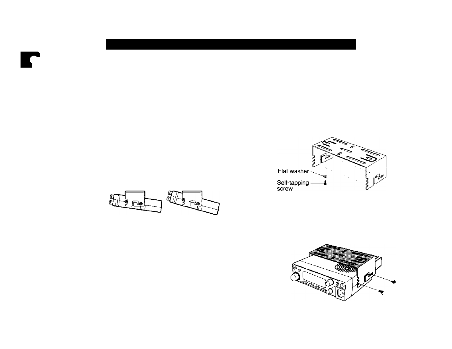
■ Installation Example
Use the supplied mounting bracket to install the
transceiver inside your vehicle. To enjoy the best
viewing angle, you can position the transceiver in the
bracket in a number of ways as shown below.
—I in^
If mounted underdash, the bracket must be installed
so that the 3 screw holes on the edge of each bracket
side are facing forward. This allows you to mount the
transceiver horizontally or to angle it fonvard.
If mounted with the bracket opening facing upward,
position the bracket with the 3 holes facing the rear to
angle the transceiver upward. Position the bracket
with the 3 holes facing forward if you plan to angle the
transceiver downward. The transceiver can be
mounted horizontally, angled neither up nor down, with
the bracket positioned either way.
2 Position the transceiver, then insert and tighten the
supplied hexagon SEMS screws and washers.
There are 2 screws and 2 washers supplied for each
side of the bracket.
Installation Steps
1 Install the mounting bracket in the vehicle using the
supplied flat washers and self-tapping screws.
There are 4 washers and 4 screws supplied.
• The bracket can be mounted with the bracket opening
for the transceiver facing down for underdash
mounting, or with the opening facing up.
• Double check that all hardware is tightened to prevent
vehicle vibration from loosening the bracket or
transceiver.
SEMS screw
Page 9
DC POWER CABLE CONNECTION
■ Mobile Operation
The vehicle battery must have a nominal rating of 12 V.
Never connect the transceiver to a 24 V battery. Be
sure to use a 12 V vehicle battery that has sufficient
current capacity. If the current to the transceiver is
insufficient, the Display may darken during
transmission, or transmit output power may drop
excessively.
After the cable is in place, wind heat-resistant tape
arc .nd the fuse holder to protect it from moisture.
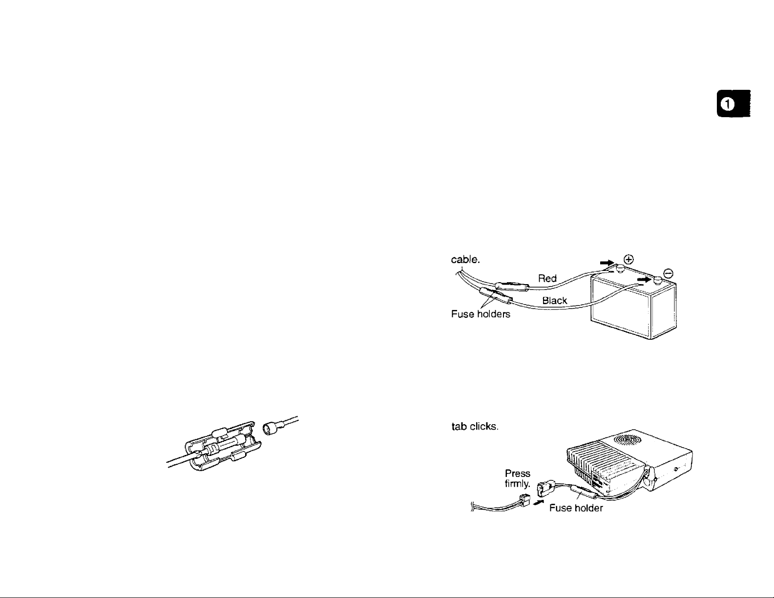
Tie down the full run of cable.
To prevent the risk of short circuits, disconnect other
wiring from the negative (-) battery terminal before
connecting the transceiver.
Confirm the correct polarity of the connections, and
attach the power cable to the battery terminals; red
connects to the positive (-i-) terminal, black connects
to the negative (-) terminal.
1 Route the DC power cable supplied with the
transceiver directly to the vehicle’s battery terminals
using the shortest path from the transceiver.
• If using a noise filter, it should be installed with an
insulator to prevent it from touching metal on the
vehicle.
• It is not recommended to use the cigarette lighter
socket since some cigarette lighter sockets introduce
an unacceptable voltage drop.
• If the power cable must be routed through a hole in the
vehicle chassis or body, for example in the firewall at
the front of the passenger compartment, use a rubber
grommet to protect the cable from abrasion.
Dismantle the fuse holder to pass the cable through
the firewall.
The entire length of the cable must be dressed so it is
isolated from heat and moisture.
• Use the full length of the cable without cutting off
excess even if the cable is longer than required. In
particular, never remove the fuse holders from the
5 Reconnect any wiring removed from the negative
terminal.
6 Connect the DC power cable to the transceiver’s
power supply connector.
• Press the connectors firmly together until the locking
Page 10
Fixed Station Operation
In order to use this transceiver for fixed station
operation, you will need a separate 13.8 V DC power
supply that must be purchased separately.
The following table lists the current capacity
recommended for power supplies used with each type
of transceiver.
Tnmss8imMod«l
TM-261A
TM-261 EJ
TM-461A
Power Supply Ca|mc%
11 A or more
4 A or more
10 A or more
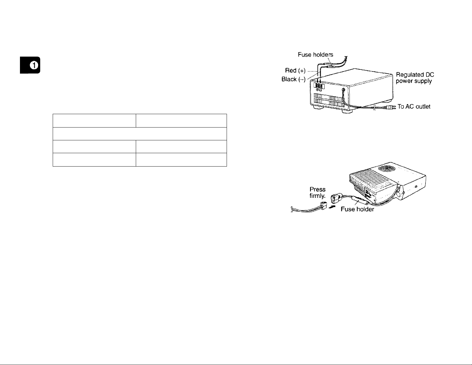
1 Connect the DC power cable to the regulated DC
power supply and check that polarities are correct
(Red: positive, Black: negative).
• DO NOT directly connect the transceiver to an AC
outlet!
• Use the supplied DC power cable to connect the
transceiver to a regulated power supply,
• Do not substitute a cable with smaller gauge wires.
2 Connect the transceiver’s DC power connector to
the connector on the DC power cable.
• Press the connectors firmly together until the locking
tab clicks.
Note:
For your trartsceiver to fully exhibit its performance capabilities,
the following optional power supply is recommended:
PS-33 (20.5 A, 25% duty cycle).
Before connecting the DC power supply to the transceiver, be
sure to svwtch the transceiver and the DC power supply OFF.
Do not plug the DC power supply into an AC outlet until you
make ail connections.
Page 11
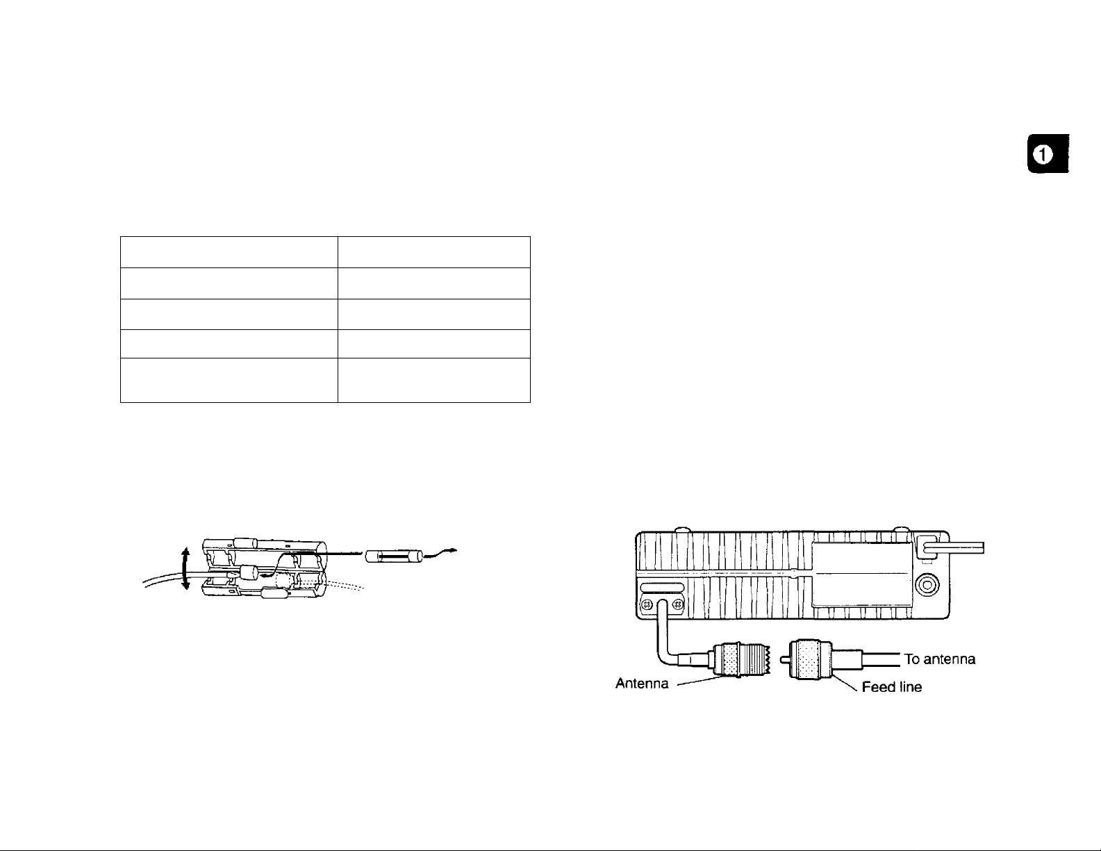
Replacing Fuses
ANTENNA CONNECTION
If the fuse blows, determine the cause then correct the
problem. After the problem is resolved, then replace the
fuse. If newly installed fuses continue to blow,
disconnect the power cable and contact your dealer or
nearest Service Center for assistance.
Rise Local^'efl
TM-261A
TM-261EJ
TM-461A
Supplied Accessory
DC Power Cable
CAUTION: Only use fuses of the specified type and rating.
Note: If you use the transceiver for a long period when the vehicle
battery is not fully charged, or when the engine is OFF, the battery
may become discharged, and will not have sufficient reserves to start
the veNcle. Avoid using the transceiver under these conditions.
Rise Currsiif Rating
15 A
4 A
10 A
20 A
Before operating, you must first install an efficient,
well-tuned antenna. The success of your installation will
depend largely on the type of antenna and its correct
installation. The transceiver can give excellent results if the
antenna system and its installation is given careful
attention.
Your choice of antenna should have a 50 impedance to
match the transceiver input impedance. Use low-loss
coaxial feed line that also has a characteristic impedance of
50 Q. Coupling the antenna to the transceiver via feed
lines having an impedance other than 50 Q reduces the
efficiency of the antenna system, and can cause
interference to nearby broadcast television receivers, radio
receivers, and other electronic equipment.
CAUTION:
♦ Transmitting without first connecting an antenna or other matched
toad may damage the transceiver. Always connect the antenna to
the transceiver before transmitting.
♦ Alt fixed stations should be equipped with a lightning arrester to
reduce ti^e risk of fire, electric shock, and transceiver damage.
connector
connector
Page 12
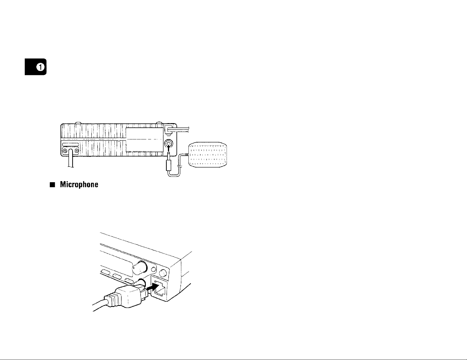
ACCESSORY CONNECTIONS
■ External Speaker
If you plan to use an external speaker, choose a
speaker with an impedance of 8 Q. The external
speaker jack accepts a 3.5 mm diameter mono
(2-conductor) plug. Recommended speakers include
the SP-50B and SP-41.
To communicate in the voice modes, plug a 600 Q
microphone equipped with an 8-pin modular connector
into the modular socket on the Front Panel of the
transceiver. Press firmly on the plug until the locking tab
clicks.
Page 13
GETTING ACQUAINTED
The following sections describe basic functions of the Front
Panel controls and buttons, Rear Pane! jacks and
connectors, microphone buttons and Display indicators.
For full explanations of functions mentioned, refer to the
appropriate sections elsewhere in the manual.
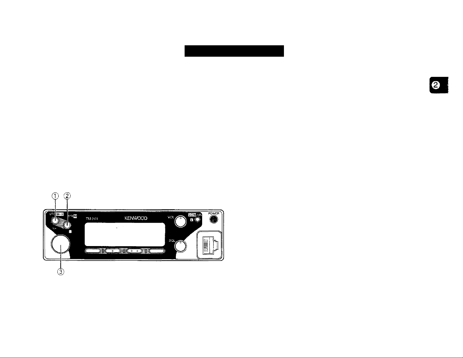
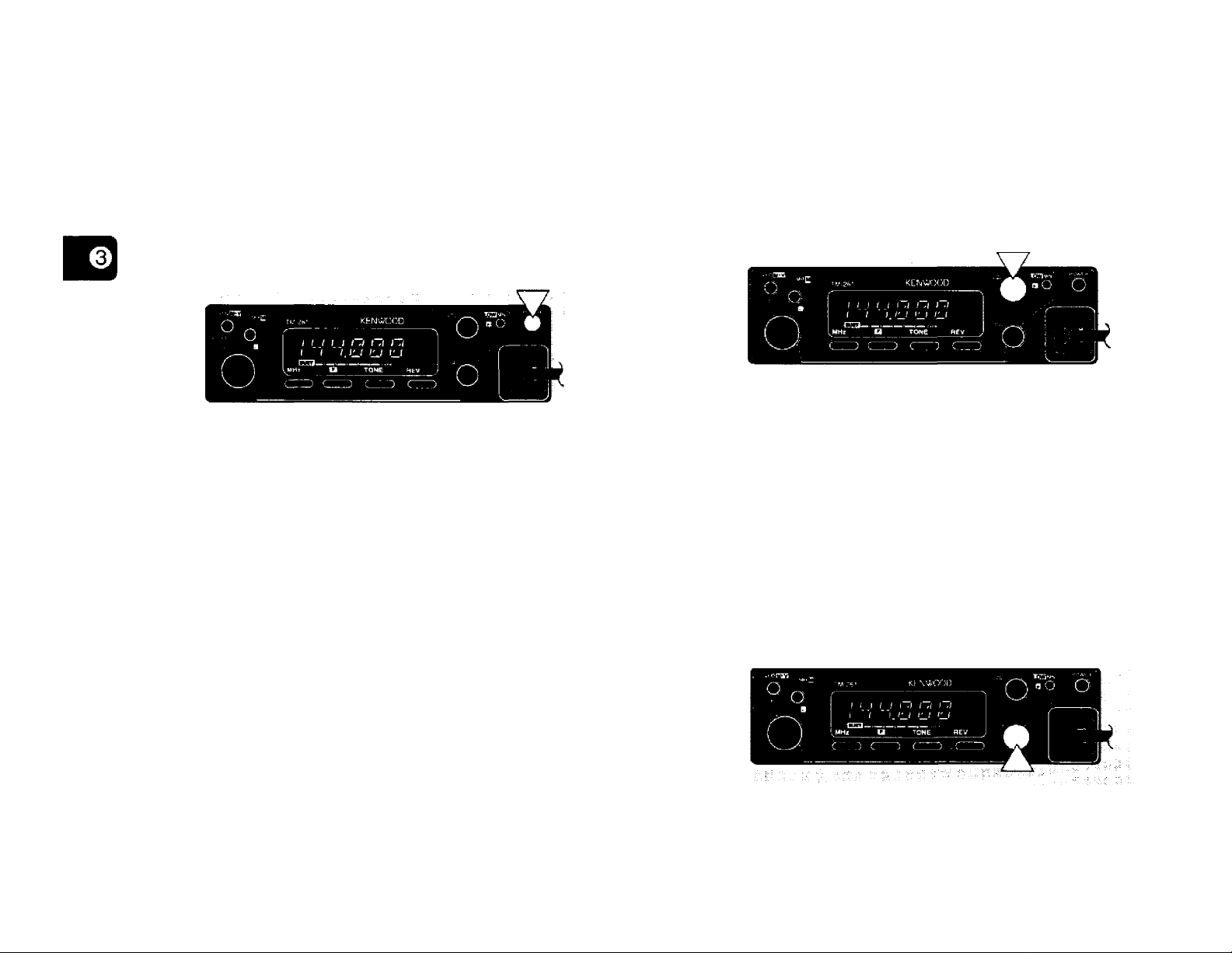
FRONT PANEL
The labels for some of the Front Panel buttons appear on
the Display instead of on the panel or buttons. The
displayed button labels change depending on which mode
the transceiver is in. This “GETTING ACQUAINTED”
section refers to the buttons that do not have labels on the
Front Panel by the labels that appear on the Display
immediately after switching ON the transceiver.
© VFO button
Selects the VFO mode {page 15}. The Tuning control
changes the transceiver frequency in this mode. Also
provides:
• Menu A or Menu B selection of choices (page 17}.
• VFO Scan start/stop to scan the entire VFO range {page 32}.
• Program Scan start/stop to scan a programmed range of
frequencies (page 34}.
© MR button
Selects the Memory Recall mode {page 26}. The Tuning
control changes the memory channel in this mode. Also
provides:
• Memory Scan start/stop {page 32}.
© Tuning control
Selects transmit/receive frequencies while in VFO mode
and memory channels while in Memory Recall mode
(pages 15, 26}. Also provides:
• Menu A or Menu B selection of function or choices (page 17].
• Program Scan limits select to choose the boundaries for this
type of scan (page 34},
• Scan direction select to choose if Scan progresses upward or
downward in frequency {pages 32, 35}.
• DTSS code select {page 37},
Page 14
0 ®
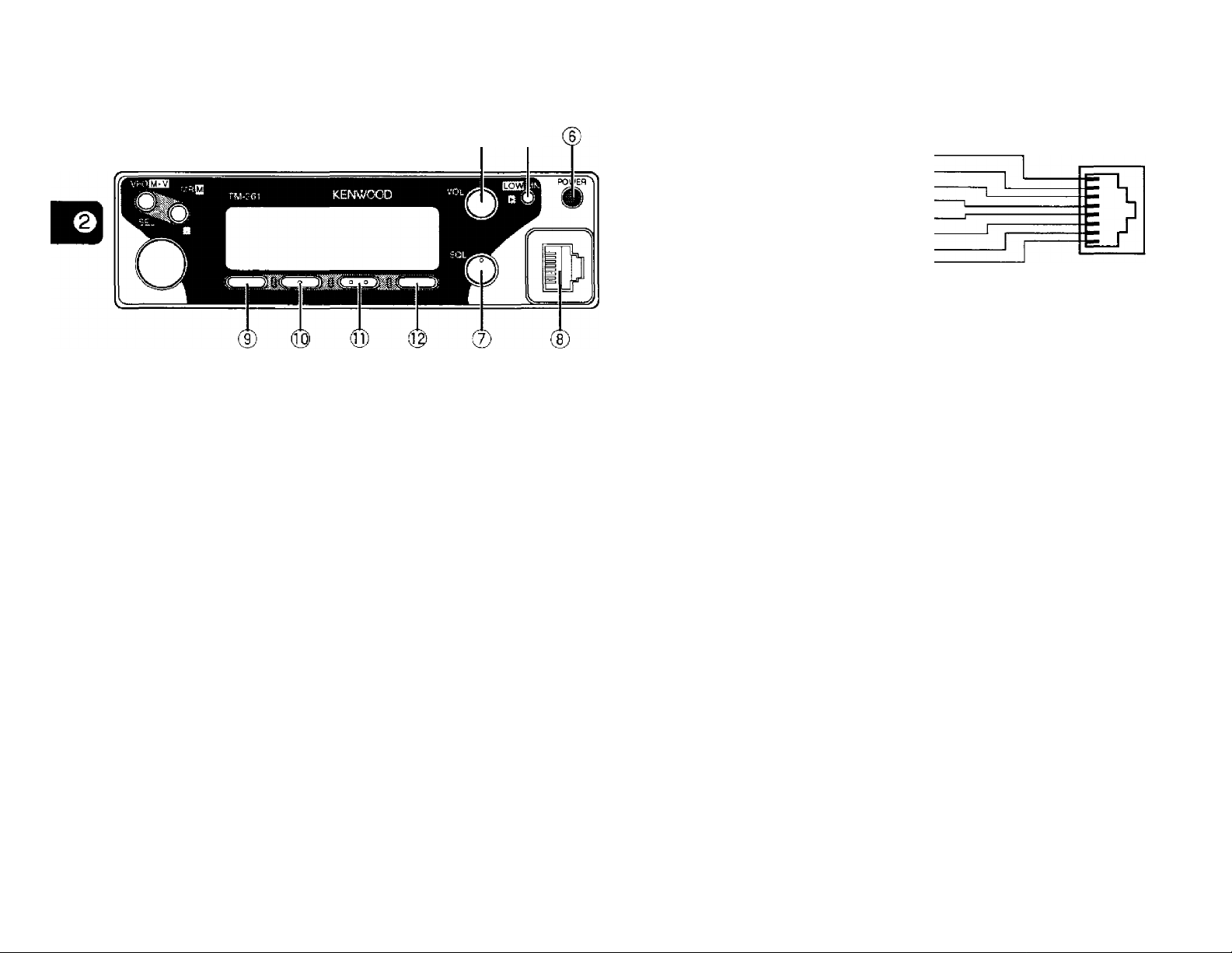
® VOL control
Adjusts the level of receive audio from the speaker
{page 14}.
(D MN button
Selects the Memory Name mode {page 30}.
CD POWER switch
UP
-----------------------
DC 8 V, 200 mA max.
GND
--------
STBY (PTT) ■
GND (MIC) ■
MIC
--------RD : Open squelch audio (100 mV/10 ki2)
OWN
----------------------------------------------
® MHz button
Selects the MHz mode. This mode allows you to use the
Tuning control or the microphone [UP]/[DWN] buttons to
change the transceiver frequency in 1 MHz steps.
Also provides:
• AM/FM mode select (some TM-261A versions only)
{page 48}.
® F (Function) button
Allows you to select the different functions that are
available on multifunction buttons.
Switches the transceiver ON or OFF {page 14}.
© SQL (Squelch) control
Adjusts the squelch threshold level {page 14}. This allows
you to mute speaker output while no stations are being
received.
® Microphone connector
Insert the 8-pin modular connector plug until the locking tab
“clicks”.
8
---
----------------------------------------------------------------
© TONE button
Switches the Tone function ON or OFF {page 22}. When
the optional TSU-8 is installed, also switches the CTCSS
function ON or OFF. Also provides:
• Automatic Tone frequency ID activate/deactivate {page 36}.
® REV (Reverse) button
Switches the transmit frequency and receive frequency
when operating with a transmit offset or a split memory
channel {page 23}.
Page 15
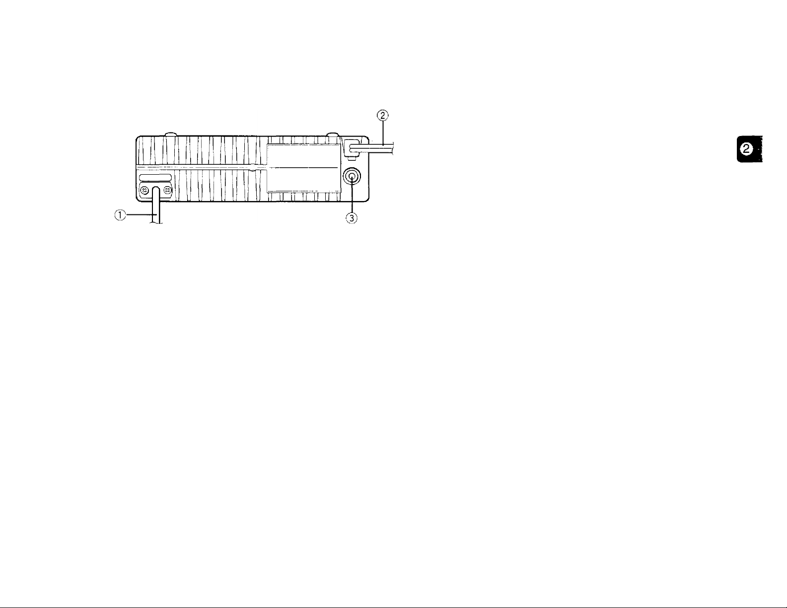
REAR PANEL
© Antenna cable
Connect an external antenna {page 5}. When making test
transmissions, connect a dummy load in place of the
antenna. The antenna system or load should have an
impedance of 50 £2. The connector accepts a male
PL-259 connector.
© Power Input 13.8 V DC cable
Connect a 13.8 V DC power source. Use the supplied DC
power cable (pages 3,4}.
© Speaker jack
If you wish, connect an optional external speaker for clearer
audio. Accepts a 3.5 mm diameter, 2-conductor plug.
Page 16
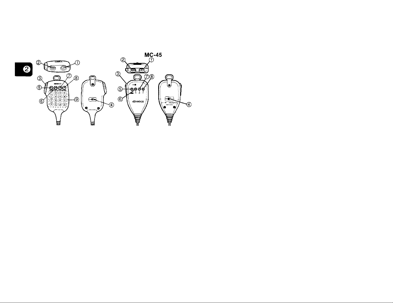
MICROPHONE
CD CALL key
MC-53DM
(D UP button
(D DWN button
Raises or lowers the VFO frequency, the memory channel
number, the Tone/CTCSS frequency, or the DTSS code.
Holding either button down causes the action to be
repeated. Also, switches between values when selecting
values for functions with multiple choices.
Recalls the Call channel. Pressing for more than 1 second
initiates the Call/VFO Scan {page 35} or the Call/Memory
Scan {page 35}.
® VFO key
0 MR key
Identical to the Front Panel functions of the same names.
Both keys can be re-programmed, if desired {page 47}.
CD PF key
Depending on which function you select by accessing “PF”
in Menu B (page 48}, the function of this key differs. Refer
to “CONFIGURING PROGRAM FUNCTION KEYS"
{page 47}.
® DTMF keypad (MC-53DM only)
The 16-key keypad is used with the DTMF functions, or to
directly enter a freqeuncy or a memory channel number.
(3) PTT (Push-to-talk) switch
Press to transmit; release to receive. Also used to exit
various functions such as Scan, DTSS code select, or
Tone/CTCSS frequency select.
® LOCK switch
Locks all microphone functions except [PTT] and the
DTMF keypad, if equipped.
10
Page 17

DISPLAY
® CT
Ф
wO R CT DT CO MENU j
* S \ ДРД
(3) (4) ® ® ®
-1
----
3-------5
7
------9-------
OVER
ON AIR
LM
Ф
Indicates the Transceiver Lock function is ON {page 46}.
® - +
Indicates the transmit frequency is offset (different) from the
receive frequency {page 22}. The symbol displayed (either
“ + ” or “ - ”) indicates the direction that the transmit
frequency is offset from the receive frequency. +”
appears when a split-frequency memory channel is
selected {page 25}.
® R
Indicates the Reverse function is ON {page 23}. Transmit
and receive frequencies are reversed. If any frequency is
selected for ‘TONE.RX” in Menu B, RX Tone frequency and
TX Tone frequency also are reversed. Refer to “Selecting a
Tone Frequency” {page 23}.
‘T' indicates the subaudible Tone encoder function is ON
{page 22}. “CT’ indicates the CTCSS function is ON
{page 36} provided the optional TSU-8 CTCSS unit is
installed {page 54}.
(D DT
Indicates the Dual Tone Squelch System (DTSS) is ON
{page 37}.
® CO
Indicates Carrier-Operated Scan Resume is ON {page 31}.
When not visible, Time-Operated Scan Resume is in effect.
(7) MENU
Visible while accessing Menu A or Menu B {page 17}.
® S.Mli.i.ts
Displays the transmit/receive frequency, frequency step
{page 45}, Offset frequency {page 21} and other data. Also
displays the menu selections when using Menu Set-Up.
The 1 MHz decimal point blinks while the transceiver is
scanning {pages 32, 35}.
® gg
Displays the currently selected memory channel number
{page 26}. The first digit displays “A” or “B” depending on
which Menu is being accessed.
11
Page 18
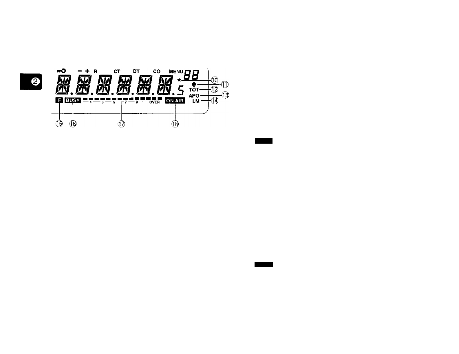
This icon indicates the selected memory channel is
locked-out and will not be scanned by Memory Scan
{page 33).
® LM
Indicates whether Low (L) or Medium (M) transmit output
power is selected {page 16}. When neither “L” nor “M" is
visible, High output power is selected.
® B
Appears when the [F] button is pressed. Indicates
alternate functions of multiple-function buttons can be
accessed now.
BUSY
Indicates the squelch is open and the frequency is “busy”.
Also appears when the squelch is set to minimum by
turning the SQL control fully counterclockwise. If using
either CTCSS or DTSS, indicates the squelch is open due
to a received signal that contains the same CTCSS tone or
DTSS code that is programmed in your transceiver.
Indicates AM receive mode is ON {page 48). AM mode is
available only on some TM-261A versions only.
® TOT
Indicates the Time-out Timer function is ON {page 46).
Blinks while accessing Menu B, ‘ТОГ’.
® APO
Indicates the Automatic Power Off function is ON
{page 46}.
12
OVER
In Receive, acts as an S-meter to indicate the signal
strength of received signals. In Transmit, acts as an RF
power meter to indicate the relative transmit output power
{page 16}. Full scale represents High transmit power.
ON AIR
indicates the transceiver is in Transmit mode with a
transmit frequency selected that is within a transmit band.
Page 19
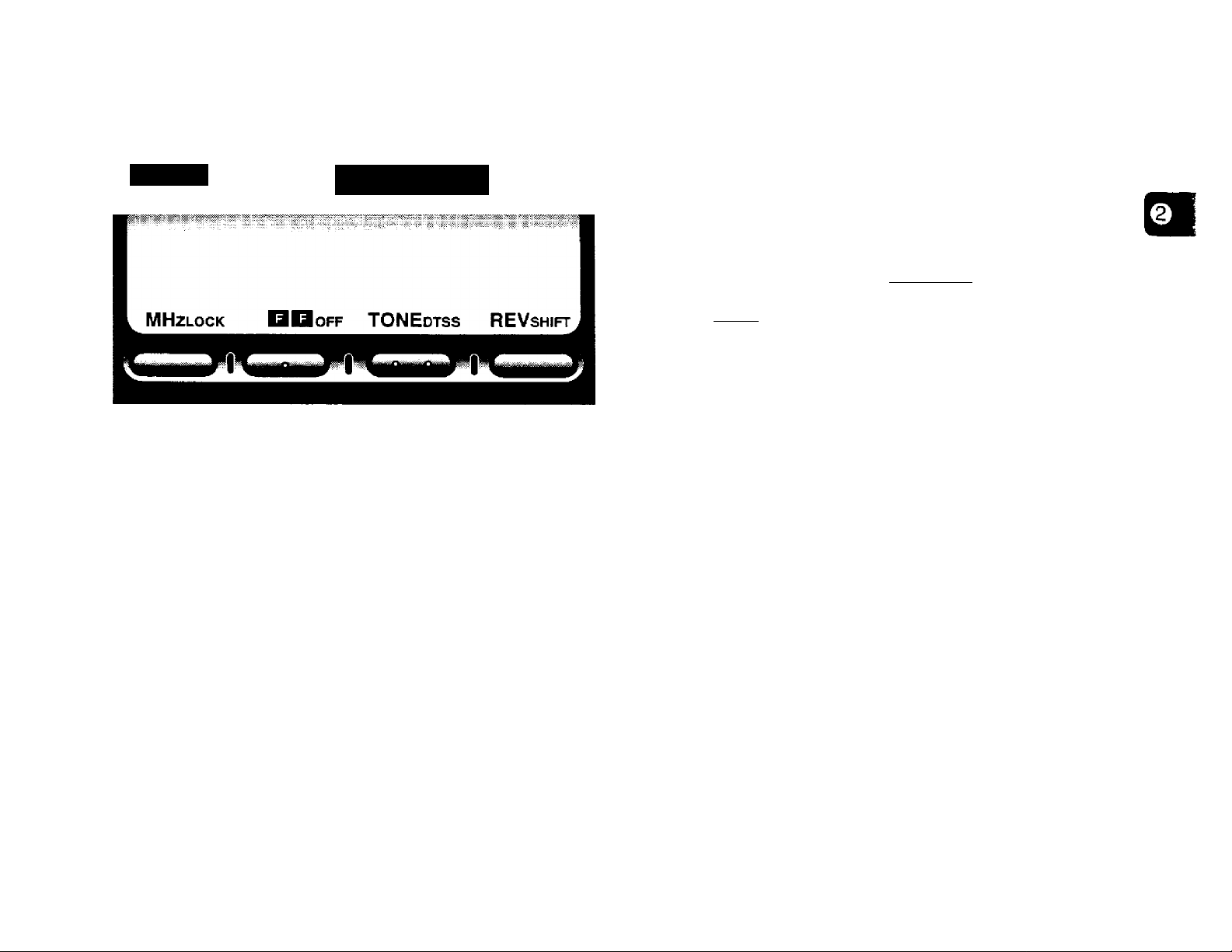
BUTTON FUNCTION DISPLAY
Basic State Display Labels
TM-261
Some of the Front Panel buttons have more than one
function. This allows us to provide many functions on your
transceiver but keep the transceiver case small. To simplify
operation, the lower portion of the Display has labels that
indicate the current function of each of the 4 buttons on the
lower edge of the Front Panel. The label appears
immediately above its corresponding button.
When using any of the alternate functions of the multiple
function buttons, you have 10 seconds to select an
alternate function after pressing the [F] button. Pressing
[F] again or waiting for 10 seconds restores the Basic state
with button definitions of [MHz], [F], [TONE], and [REV].
KENWOOD
MHz
—and
Labels After Pressing [F]
LOCK ■ off DTSS SHIFT
TONE REV
J
13
Page 20
SWITCHING POWER ON/OFF
ADJUSTING VOLUME
1 Switch ON the DC power supply.
• If operating mobile, skip this step.
2 Press the POWER switch to switch ON the transceiver.
To switch OFF the transceiver, press the POWER
switch again.
* In a fixed installation, after the transceiver has been
switched ON, it can then be switched OFF or ON by using
only the power switch on the DC power supply.
Turn the VOL control clockwise to increase the audio level
and counterclockwise to decrease the level.
ADJUSTING SQUELCH
The purpose of squelch is to silence audio output from the
speaker when no signals are present. When squelch is set
correctly, you will hear sound only while a station is actually
being received. The point at which ambient noise on a
frequency just disappears, called the squelch threshold,
depends on the frequency.
Turn the SQL control clockwise to just eliminate the
background noise when no signal is present.
14
Page 21

SELECTING FREQUENCIES
■ Tuning Control
• Frequencies can also be selected via the microphone
keypad (MC-53DM only). See “KEYPAD DIRECT
ENTRY” {page 43}.
Using the Tuning control is convenient when you are
within easy reach of the transceiver Front Panel, and
the frequencies to be selected lie near the current
frequency.
1 Press [VFO] to select VFO mode.
Q “ o O
> I i } I { .I I .1 t .I
I I i;_t
KMHt Li
_________rOHE REV
O I "
2 Turn the Tuning control to select a receive
frequency.
Microphone [UP]/[DWN] Buttons
Using microphone [UP]/[DWN] for frequency selection
is useful when mobiling or any time you are not
immediately in front of the transceiver.
Press [UP] or [DWN] once to change the receive
frequency by one frequency step in the direction
indicated by the button.
• Pressing and holding either button causes the frequency
to step repeatedly in one direction until the button is
released.
Clockwise rotation increases the frequency one
frequency step at a time.
Counterclockwise rotation decreases the frequency
one step at a time.
If you cannot select a particular receive frequency, the
frequency step size needs to be changed. See
“CHANGING FREQUENCY STEP SIZE” (page 45} for
further information.
15
Page 22

TRANSMITTING
Selecting Output Power
When ready to begin transmitting, press and hold [PTT]
and speak in a normal tone of voice. Speaking too close to
the microphone, or too loudly, may increase distortion and
reduce intelligibility of your signal at the receiving station.
MC-53DM
It's wise, and required by law, to select the lowest power
that allows reliable communication. If operating from
battery power, lower transmit power will give you more
operating time before a charge is necessary. Reducing
power lowers the risk of interfering with others on the
band too.
Press [F], [MN] to select the transmit power you
require.
Each time this key operation is repeated, the transmit
power is changed as shown below.
High
(No Indicator)
Medium
("M")
Low-I
("L")
16
• The transmit power cannot be changed while transmitting.
Page 23

MENU DESCRIPTION
Many functions on this transceiver are selected or
configured via software-controlled menus instead of
physical controls on the transceiver. The menus are
identified as Menu A and Menu B. Menu A is used to
access functions that are frequently changed while Menu B
is used for less frequently changed functions.
MENU ACCESS
1 To access Menu A, press [F] (1 s).
Q^o O
t i /
i
UH.r u Tone pev
To access Menu B, press [F]+ POWER ON.
3 The method for selecting the desired menu selection
differs depending on which menu function you selected
in Step 2.
• To toggle between two selections or to select from three
selections, press [VFO].
• To select from more than three selections, press [VFO],
then turn the Tuning control or press microphone
[UP]/[DWN].
• To select for the menu functions listed below, refer to the
corresponding reference pages:
DTSS Code (Menu A):
“STORING DTSS CODES” on page 37
Memory Channel Lockout (Menu A):
“Locking Out Memory Channels” on page 33
Program Scan (Menu B):
“PROGRAM SCAN” on page 34
DTMF Number Storing (Menu B):
“STORING DTMF NUMBERS FOR THE AUTOMATIC
DIALER” on page 40
DTMF Number Confirmation (Menu B):
“CONFIRMING STORED DTMF NUMBERS” on page 41
2 Select the desired menu function by turning the Tuning
control or by pressing microphone [UP]/[DWN].
4 Press [F] or microphone [PTT] to exit Menu A or
Menu B.
Note:
♦ If neither key strokes are made nor controls are turned within
approximately 10 seconds after Menu A or Menu B is accessed, the
frequency display is restored.
♦ When either Menu A or Menu B is accessed after the Reverse
function is activated. Reverse is canceled.
afsmmmmfm
17
Page 24

MENU A CONFIGURATION
Memibriiii
F.S Frequency Step Size^
O.S
TO Tone Frequency
DT.C DTSS Code
CH.D
SON Scan Resume Method
MR.L
Transmit Offset (Shift)
Channel Display
Memory Channel Lockout®
OesoriilliDit
^eeiloiis Detaolt
12.5 kHz/ 25 kHz/ 5 kHz/10 kHz/
15 kHz/ 20 kHz
5 kHz (or 12.5 kHz)® - 20 MHz
(using current frequency step size)
Standard 38 Tone frequencies
000 - 999
OFF/ON
Time-Operated/ Carrier Operated
OFF/ON
TM-261A (U.S.A./ Canada): 5 kHz
TM-261A (General): 12.5 kHz
TM-261 EJ: 20 kHz
TM-461A: 25 kHz
TM-261 A/TM-261 EJ: 600 kHz
TM-461A: 5 MHz
TM-461A(China): 10 MHz
88.5 Hz
000
OFF
Time-Operated
OFF
45
21
23
37
29
31
33
^ Cannot be selected in the Memory Channel mode.
2 The minimum selectable offset frequency is dependent on the current frequency step.
^ Cannot be selected in the VFO or Call Channel mode.
18
Page 25

MENU B CONFIGURATION
Me«tt Label Oesca’lption
ВЕР
TOT
APO
ARO
BCL
PF
PGM.SCN
DTMF.IN
DTMF.CK
TONE.RX
Confirmation Beep
Time-Out Timer
Automatic Power Off
Automatic Repeater Offset^
Busy Channel Lockout
PF Key Programming
Program Scan
DTMF Number Storing
DTMF Number Confirmation
RX Tone Frequency^
DTD DTSS Delay Time
DT.G
DTSS Group Code
Selectkti»
OFF/ON
OFF/ON
OFF/ON
OFF/ON
OFF/ON
USeR setting/ MONitor/ ENTer
Upper limit/ Lower limit
16 digits maximum
Stored DTMF number
Standard 38 Tone frequencies
350 ms/ 550 ms/ 750 ms
OFF/A/B/C/D/E/F
Default Page
ON
OFF
OFF
ON
OFF
User setting
Current VFO frequency
—
—
OFF
350 ms
OFF
—
46
46
22
46
48
34
40
41
23
39
38
^ Available on some TM-261A versions only.
2 Available only when the optional TSU-8 is installed.
19
Page 26

OPERATING THROUGH REPEATERS
Compared to simplex communication, you can usually
transmit over much greater distances by using a repeater.
Repeaters are typically located on a mountain top or other
elevated location. Often they operate at higher ERP
(Effective Radiated Power) than a typical station. This
combination of elevation and high ERP allows
communications over considerable distances.
Repeaters are often installed and maintained by radio
clubs, sometimes with the cooperation of local businesses
from communications industries. During emergencies,
repeater networks can be a valuable aid to officials
responsible for coordinating communications in a
community.
REPEATER ACCESS
Most Amateur Radio voice repeaters use a separate
receive and transmit frequency. The transmit frequency
may be higher or lower than the receive frequency but the
difference in frequencies will be a standard amount, or
“standard split”. You can set a separate receive and
transmit frequency by selecting the offset frequency and
offset direction with respect to the receive frequency.
Instead of manually selecting the offset frequency, you can
also use Automatic Repeater Offset (some TM-261A
versions only).
In addition, some repeaters may require the transceiver to
transmit a Tone before the repeater can be used. To
transmit this required Tone, activate the Tone function and
select a Tone frequency. The required Tone frequency
depends on the repeater you are accessing.
Most repeater configurations fall into one of the following
categories:
Offisel Direetfon
TSI*461A
20
RX: 145.33 MHz
+
—
+600 kHz
-600 kHz
+5 MHz
(China: +10 MHz)
-5 MHz
(China: -10 MHz)
Page 27

FLOW CHART FOR REPEATER ACCESS
Selecting Offset Frequency
Select how much the transmit frequency will be offset
from the receive frequency.
Press [F] (1 s) to access Menu A.
1
\7
Select an offset frequency.
<7
Select an offset direction.
Activate theTone function, if necessary.
<>
Select a Tone frequency, If necessary.
O
2
Select “O.S” {page 17}.
• The current offset frequency appears.
MENU rt
n r m o Hi n
u. u u. u u u
MHz
3 Select the appropriate offset frequency within
20 MHz of the receive frequency.
• The setting for “FS" (Menu A) determines the
frequency steps used while you are selecting the
offset frequency.
• The minimum selectable offset frequency is dependent
on the current frequency step.
TONE
4 Press [F] or microphone [PTT] to exit Menu A.
Note: Selections must be made within approximately 10 seconds or
the previous mode is restored.
REV
21
Page 28

Selecting Offset Direction
Select whether the transmit frequency will be higher (+)
or lower {-) than the receive frequency.
Press IF], [SHIFT].
• Each time this key operation is repeated, the offset
direction changes as shown below.
►-Simplex—>“ + —- —
Automatic Repeater Offset
(Some TM-261A Versions Only)
This function allows the transceiver to automatically take
care of setting the required offset direction of the
transmit frequency from the receive frequency. Access
“ARC” in Menu В in order to toggle Automatic Repeater
Offset either ON or OFF {page 17}. The default is ON.
The transceiver is programmed for offset direction as
shown below.
51 ■—
If the offset transmit frequency falls outside the transmit
band, transmit is inhibited until the transmit frequency is
brought within the band limits by one of the following
methods:
• Move the receive frequency further inside the band,
• Reverse the offset direction.
Note: When a split memory channel is currently in use, the offset
direction cannot be reversed.
144.0 145.5 146.4 147.0 147.6
145.1 146.0 146,6 147.4 148.0 MHz
-
s
-i-
s
- +
s
-
s
S: Simplex
Note: Automatic Repeater Offset is not activated when CTCSS
{page 36} or Reverse (page 23} is ON.
Activating Tone Function
Each press of [TONE] switches through the choices
shown below.
No Indicator
I
TONE
("T")
CTCSS
("CT")
The CTCSS indicator does not appear if the optional
TSU-8 is not installed.
22
Page 29

Selecting a Tone Frequency
REVERSE FUNCTION
To select the same Tone frequency for transmitting and
receiving, access ‘TO” in Menu A {page 17). The Tone
frequencies listed below can be selected:
Freq.
Mo.
(Hz)
01
67.0
02 71.9
74.4
03
04
77.0
79.7
05
62.5
06
07
85.4
08
88.5
09
91.5
10 94.8
To select a Tone for receiving that is different from the
Tone used for transmitting, access TONE.RX” in Menu В
(page 17), and select a frequency. The frequency
selected here is used as the RX Tone frequency, and the
frequency selected for ‘TO” in Menu A is used as the TX
Tone frequency.
No.
11
12
13
14
15
16
17
18
19
20
Frai[.
(Hz) (Hz) (Hz)
97.4
100.0
103.5
107.2
110.9
114.8
118.8
123.0
127.3
131.8
Freq.
No.
21
136.5
22
141.3
23
146.2
24
151.4
25 156.7
26
162.2
27
167.9 37
28
173.8 38
29
179.9
30
186.2
Freq.
No.
192.8
31
203.5
32
210.7
33
34 218.1
225.7
35
233.6
36
241.8
250.3
When used while monitoring a repeater, the Reverse
function allows you to manually check the signal strength of
a station accessing the repeater. If the station’s signal is
strong, it’s best to move to a simplex frequency to continue
the contact and free up the repeater.
Press [REV] to toggle the Reverse function ON or OFF.
• The receive frequency and the transmit frequency are
exchanged. “R” appears when the function is ON. The
default is OFF.
- R
t u и c о c
I ( LU f
MHz
V
___
If any Tone frequency is selected for ‘TONE.RX” in Menu B,
the RX Tone frequency and the TX Tone frequency also are
reversed.
If reversal would place the receive frequency outside the
receive frequency range, an error beep sounds when [REV] is
pressed. No reversal occurs.
Automatic Repeater Offset does not function while Reverse is
ON.
_________
----S-------
OVER
TONE REV
I
23
Page 30

MEMORY CHANNELS
A total of 62 memory channels (1 - 62) are available for
storing frequencies and related data. Each memory
channel can be used either as a simplex channel or split
channel for storing any frequency or frequency pair that
can be selected on the transceiver. Alternatively, a
standard offset and offset direction required for using
repeaters can be stored. Refer to “OPERATING
THROUGH REPEATERS" {page 20}.
STORING DATA IN MEMORY
There are 2 methods of storing transmit/receive
frequencies and associated data in memory channels
depending on the relationship of the transmit and receive
frequencies:
• Simplex memory channels:
RX frequency = TX frequency
• Split memory channels:
RX frequency ^ TX frequency
The data listed below can be stored in each memory
channel:
PaiBiitelbir
RX frequency
TX frequency
RX Tone (CTCSS) frequency
TX Tone (CTCSS) frequency
Tone or CTCSS status
Frequency step
Offset direction, Offset status
Reverse status
DTSS code, DTSS status
Memory channel name
YES: Can be stored in memory.
N/A: Not applicable
Slmpl№[ ;
Cftatiitei
YES
YES
YES
YES
YES
YES
YES
YES
YES
Spilt
Chaaiiat
YES
YES
YES
YES
YES
YES
N/A
N/A
YES
YES
24
Page 31

Simplex Memory Channels
Split Memory Channeis
1 Select the desired frequency and associated data
(Tone, CTCSS, DTSS, etc.) using VFO mode,
Memory Recall {page 26}, or the Call channel
{page 27).
2 Press [F] to enter Function Select mode.
• “P and a memory channel number appear.
I u u o Hi m
f t LU u u
-5
---
7-
LOCK
3 Turn the Tuning control, or press microphone
loFF
[UP]/[DWN], to select the desired memory channel.
4 Press [MR].
• The selected frequency and associated data are
stored in the memory channel, A transmit frequency
from a split memory channel or split Call channel is not
stored.
• If the memory channel selected in the previous step
already contained data, the new data ovenrtrrites the
previous data.
• The previous mode is restored.
OVER
DTSS
SHIFT
1 Select the desired receive frequency, and associated
data (Tone, CTCSS, DTSS, etc.) using VFO mode,
Memory Recall (page 26} or the Call channel
{page 27}.
2 Press EF] to enter Function Select mode.
• “P and a memory channel number appear.
3 Turn the Tuning control, or press microphone
[UP]/[DWN], to select the desired memory channel.
4 Press [MR] (1 s).
• “ - + ” appears.
\
t Vj u o Hi m
( f L u u u
MHz
• The channel number is visible if using Memory Recall
mode and the Call channel “C” is visible if using Call
channel mode in Step 1.
Turn the Tuning control, or press microphone
[UP]/[DWN], to select the desired transmit
frequency.
TONE
REV
Note: After completing each of Steps 2 and 3, you must execute the
next step within approximately 10 seconds or the previous mode is
restored.
25
Page 32

6 Press [MR].
• The selected transmit frequency is stored in the
memory channel, and the previous mode is restored.
• Associated data selected in Step 1 such as Tone
status/frequency, the frequency step, and DTSS
status/code are not altered by this step. However,
Transmit Offset status and Reverse status are erased.
• Storing a receive frequency in a split memory channel
erases any previous data in that channel.
Note: After completing each of Steps 2 ~ 5, you must execute the
next step within approximately 10 seconds or the previous mode is
restored.
RECALLING MEMORY CHANNELS
ERASING MEMORY CHANNELS
Although it is possible to ovenwrite existing data in any of
the memory channels with new data, at times you may
want to ciear data from memory channels without entering
new data. It’s convenient to clear channels no longer used
so you can identify channels that are free for memorizing
new frequencies. Memory channels that contain no data
cannot be recalled while in Memory Recall.
1 Press [MR] to select Memory Recall.
2 Turn the Tuning control, or press microphone
[UP]/[DWN], to select the desired memory channel.
3 Switch OFF the power to the transceiver.
4 Press [MHz]+POWER ON.
1 Press [MR].
• The memory channel used last is recalled.
2 Turn the Tuning control, or press microphone
[UP]/[DWN], to select the desired memory channel.
• Clockwise or microphone [UP]:
Increases the channel number.
• Counterclockwise or microphone [OWN]:
Decreases the channel number.
• Empty memory channels cannot be recalled.
• If [VFO] is pressed, the VFO mode is restored.
Note:
♦ Memory channels can also be recalled via the microphone keypad.
See "Memory Channel Number Entry” {page 44}.
♦ When a split memory channel is recalled, +" appears on the
Display. Press [REV] to display the transmit frequency.
26
• The contents of the selected memory channel are erased.
Note: Memory channel 1 cannot be erased.
Page 33

CALL CHANNEL
Recalling the Call Channel
The Call channel can be used to store any frequency and
related data that you want to recall frequently. The Call
channel can be programmed with a simplex or split
frequency as well as related data that can be stored in the
memory channels. No matter what mode the transceiver is
in, the Call channel always can be selected quickly. You
may want to dedicate the Call channel as an emergency
channel within your group. In this case, the CallA/FO scan
{page 35} will be useful.
The default frequency stored in the Call channel is shown
below.
Version
U.S.A./Canada
TM-261A/
TW*26fEJ
144 MHz
TM-461A
440 MHz
400 MHz
China
-
or
450 MHz
General
144 MHz
430 MHz
The contents of the Call channel cannot be deleted;
however, you can overwrite old data with new data as
described in the next section.
Simply press microphone [CALL] to retrieve the
contents of the Call channel.
• “C” appears on the Display.
/ u u nt m m -
/ f LU u fU
-7
MHz
--------S--------
• If microphone [CALL] is pressed again, “C” clears and the
previous mode is restored.
• The Tuning control and microphone [UP]/[DWN] do not
function while the Call channel is selected.
Changing Call Channel Contents (Simplex)
1 Select the desired frequency and associated data
(Tone, CTCSS, DTSS, etc.) using VFO mode or
Memory Recall {page 26}.
2 Press [F], microphone [CALL].
• The selected frequency and associated data are
stored in the Call channel. A transmit frequency from
a split memory channel is not stored.
• The previous mode is restored.
TONE
OVER
REV
27
Page 34

Changing Call Channel Contents (Split)
MEMORY ^ VFO TRANSFERS
1 Select the desired frequency and associated data
(Tone, CTCSS, DTSS, etc.) using VFO mode or
Memory Recall {page 26}.
2 Press [F], microphone [CALL] (1 s).
• +” appears.
--------------------------------------------------------------------------------^
/ ill u ni Hi m
I I uu u lU
^MHz
• The channel number is visible if using Memory Recall
mode in Step 1.
3 Turn the Tuning control, or press microphone
[UP]/[DWN], to select the desired transmit
frequency.
4 Press microphone [CALL].
• The selected transmit frequency is stored in the Call
channel, and the previous mode is restored.
TONE
REV
Transferring the contents of a memory channel or the Call
channel to the VFO can be useful if you want to search for
other stations or a clear frequency near the selected
memory channel or Call channel frequency.
1 Press [MR] to select Memory Recall. If you want to
select the Call channel, press microphone [CALL].
2 Recall the desired memory channel by turning the
Tuning control or pressing microphone [UP]/[DWN].
• This step is not necessary if the "Call channel was selected
in Step 1.
3 Press [F], [VFO].
• The complete contents of the memory channel or the Call
channel are copied to the VFO. VFO mode is selected
after the transfer is completed.
• A transmit frequency from a split memory channel or split
Cali channel is not transferred to the VFO.
• Associated data selected in Step 1 such as Tone
status/frequency, the frequency step, and DTSS
status/code are not altered by this step. However,
Transmit Offset status and Reverse status are erased.
Note: After completing each of Steps 2 and 3, you must execute the
next step within approximately 10 seconds or the previous mode is
restored.
28
Page 35

INITIALIZING MEMORY
Defaults
If your transceiver seems to be malfunctioning, initializing
the transceiver may resolve the problem.
Remember that initializing the memory channels requires
that you re-enter any memory channel data again after the
initialization, if you want to use those channels. On the
other hand, to erase all data from all channels, initialization
is a quick way to do this.
■ Partial Reset (VFO)
To initialize all settings except the memory channels, the
Call channel, and the Menu settings, press
[VFOJ+ POWER ON.
■ Full Reset (Memory)
1 To initialize all settings, press [MR]+ POWER ON.
•lO----------+ R CT DT CO MENU»-/#”»
M kfJ M
ét. m. m. m. m. s
MHZLOCK BBoFF TONEdtss
♦
TOT
APO
Eoa LM
REVshift
2 While the display shown above is visible, press [MR]
again.
• The VFO, memories, and Menu settings are reset.
Note: After the display shown above appears, you must execute
Step 2 within approximately 10 seconds or the Full Reset will be
aborted and the previous mode will be restored.
—3
m
<
CO
CM
1
CD
CM
1
Version
U.S.A./
Canada
General
Genera!
VFO
Freqitenoy
144 MHz
144 MHz
145 MHz 20 kHz 88.5 Hz
Frequeeey
Step
Tone
Fraiitraeey
5 kHz 88.5 Hz
12.5 kHz 88.5 Hz
1-
U.S.A./
440 MHz
25 kHz
88.5 Hz
Canada
1-
<
CO
1
2
China
General
400 MHz
or
450 MHz
430 MHz
25 kHz
88.5 Hz
25 kHz 88.5 Hz
CHANNEL DISPLAY FUNCTION
When this function is switched ON, the transceiver selects
Memory Recall and displays only a memory channel
number instead of a frequency.
With the Channel Display function ON, memory channels
can be selected using the Tuning control or microphone
[UPMDWN] as usual. Only memory channels containing
data can be selected.
Access “CH.D" in Menu A to toggle the function ON or OFF
{page 17}.
29
Page 36

NAMING MEMORY CHANNELS
You can name memory channels using up to 6 characters
and 5 dots. When you recall a named memory channel, its
name appears on the display instead of the stored
frequency. Names can be callsigns, repeater names,
cities, persons’ names, etc.
7 Repeat Steps 5 and 6 to enter up to 6 digits.
• When you enter less than 6 digits, press [MHz], [F],
[TONE], [REV], or microphone [PTll to complete
entry.
• To re-enter the preceding digit, press [VFO].
• A dot cannot be entered after the sixth digit.
■ Storing a Name in Memory
1 Press [MR] to select Memory Recall.
2 Turn the Tuning control, or press microphone
[UP]/[DWN], to select the desired memory channel.
3 Switch OFF the power to the transceiver.
4 Press [MN]+POWER ON.
• The first digit blinks.
Turn the Tuning control, or press microphone
[UP]/[DWN], to select the first digit.
• To enter a dot after the first digit, press [MR], Pressing
[MR] again clears the dot.
After storing a name, pressing [MN] toggles between
name display and frequency display for the memory
channel.
Note:
♦ If you do not enter the next digit within 10 seconds, the digits
already entered are stored and the entry cursor is cleared.
♦ Names can be assigned only to memory channels in which you
have stored frequencies and related data.
♦ The stored names can be overwritten by repeating Steps 1-7.
♦ The stored names also are erased by clearing memory channels
{page 26}.
30
Press [MN].
• The second digit blinks.
Page 37

^
______________________________________________________________
Scan is a useful feature for hands-off monitoring of your
favorite frequencies. After becoming comfortable with how
to use all types of Scan, the monitoring flexibility gained will
increase your operating efficiency.
This transceiver provides the following types of Scan:
Type Purpose
VFO Scan
Memory Scan
General update on band activity.
Quick activity update of your
favorite frequencies.
Program Scan
Similar to VFO Scan except over
a narrower segment of the band.
_______________________________________
V
SCAN RESUME METHODS
Before using Scan, it’s necessary to decide under what
condition you want your transceiver to continue scanning
after detecting and stopping for a signal.
Access “SCN” in Menu A to choose Time-Operated Scan or
Carrier-Operated Scan. The default is Time-Operated Scan
{page 17}.
■ Time-Operated Scan
Your transceiver stops scanning after detecting a signal,
remains there for approximately 5 seconds, and then
continues to scan even if the signal is still present.
CallA/FO Scan
Monitor the Call channel plus any
VFO frequency.
Call/Memory Scan
Monitor the Call channel plus any
Memory channel.
Note:
♦ Remember to adjust the squelch threshold level (page 14} before
using Scan.
♦ Always turn OFF Monitor (page 48} before using Scan.
♦ For CTCSS operation (page 36}, Scan stops for any signal received;
however the squelch opens only for signals that contain the same
CTCSS Tone that is stored in your transceiver.
♦ For DTSS operation (page 37}, Scan stops for any signal received;
however, the squeich opens only for signals that contain the same
DTSS code that is stored in your transceiver.
♦ When both CTCSS and DTSS are ON, Scan stops for signals that
contain the matching CTCSS Tone. However, the squelch opens
only when the matching DTSS code Is received.
■ Carrier-Operated Scan
Your transceiver stops scanning after detecting a signal
and remains on the same frequency until the signal
drops out. There is a 2 second delay between signal
drop-out and scan resumption to allow time for any
responding stations to begin transmitting.
Note:
Turning the Tuning control clockwise, or pressing microphone
[UP] after a signal that has stopped Scan clears, causes
scanning to resume immediately upward.
Turning the Tuning control counterclockwise, or pressing
microphone [DWN] after a signal that has stopped Scan clears,
causes scanning to resume immediately downward.
31
Page 38

VFO SCAN
MEMORY SCAN
VFO Scan allows you to scan all frequencies from the
lowest frequency to the highest frequency on the band.
The current frequency step size is used.
1 Press [VFO] (1 s), and Scan starts at the frequency
currently displayed.
• The 1 MHz decimal blinks while scanning is in progress.
2 To reverse the scan direction, turn the Tuning control or
press microphone [UPJ/[DWN].
• Upward scan:
Turn the Tuning control clockwise, or
Press microphone [UP],
• Downward scan:
Turn the Tuning control counterclockwise, or
D
3 To cancel VFO Scan, press any key other than
Note: Squelch must be closed for Scan to function {page 14}.
Press microphone [DWN].
microphone [UP]/[DWN].
Memory Scan allows all memory channels containing data
to be scanned.
1 Press [MR] (1 s).
• The 1 MHz decimal blinks while scanning is in progress.
• Scan starts with the channel last recalled.
2 To reverse the scan direction, turn the Tuning control or
press microphone [UP]/[DWN].
• Upward scan;
Turn the Tuning control clockwise, or
Press microphone [UP].
• Downward scan:
Turn the Tuning control counterclockwise, or
Press microphone [DWN].
3 To cancel Memory Scan, press any key other than
microphone [UPJ^DWN],
Note:
At least 2 or more memory channels must contain data and must not
be locked out.
The squelch must be closed for Scan to function {page 14}.
32
Page 39

Locking Out Memory Channels
Memory channels that you prefer not to monitor while
scanning can be locked out. Lock out any memory
channel with the following procedure.
1 Press [MR] to select Memory Recall.
2 Select the memory channel to be locked out by
using the Tuning control or microphone
[UP]/[DWN1.
3 Press [F] (1 s) to access Menu A.
4 Select “MR.L” {page 17}.
5 Press [VFO] to lock out the selected channel.
• A star icon appears which indicates that the channel
has been locked out.
MENU rt
A// o /
f
MHz
• Each press of [VFO] toggles the lockout status ON
and OFF.
6 Press [F] or microphone [PTTj to exit Menu A.
Lockout for an individual channel can be canceled by
repeating the above procedure.
„ n Is /
U I 'f
------7--------
fl— OVER
TONE REV
>1
33
Page 40

PROGRAM SCAN
This type of scan is similar to VFO Scan except the
programmable aspect allows you to set scan limits to limit
the frequency range of the scan.
■ Setting Scan Limits
1 Press [F]+ POWER ON to access Menu B.
2 Select “PGM.SCN” {page 17}.
3 Press [VFO],
• “LO" and the current lower limit appears. The default
is the currently selected frequency.
MENU,
I U C O C “
I I I
MHz
_____
---->-------
TONE
f
OVER
REV
6 Turn the Tuning control, or press microphone
[UP]/[DWN], to display the desired upper limit.
• Press [MHz] if you want to change the frequency in
1 MHz steps.
7 Press [VFO] to set the upper limit.
8 Press [F] or microphone [PTT] to exit Menu B.
Note:
♦ The lower limit must be lower in frequency than the upper limit.
♦ The lower and upper frequency steps must be equal.
♦ Selections must be made within approximately 10 seconds or the
previous mode is restored.
Confirming Scan Limits
1 Press [F]+ POWER ON to access Menu B.
2 Select “PGM.SCN” (page 17).
3 Press [VFO].
• This is the lower limit.
34
Turn the Tuning control, or press microphone
[UP]/[DWN], to display the desired lower limit.
• Press [MHz] if you want to change the frequency in
1 MHz steps.
Press [VFO].
• “UP" and the current upper limit appears. The default
is the currently selected frequency.
4 Press [VFO] again.
• This is the upper limit.
5 Press [F] or microphone [PTT] to exit Menu B.
Page 41

Using Program Scan
CALL/VFO SCAN
1 Select a frequency equal to or between the
programmed scan limits.
2 Press fVFO] {1 s), and Scan starts at the frequency
currently displayed.
• The 1 MHz decimal blinks while scanning is in
progress.
3 To reverse the scan direction, turn the Tuning
control or press microphone [UP]/[DWN],
• Upward scan:
Turn the Tuning control clockwise, or
Press microphone [UP].
• Downward scan:
Turn the Tuning control counterclockwise, or
Press microphone [DWN].
4 To cancel Program Scan, press any key other than
microphone [UP]/[DWN].
Note:
♦ Squelch must be closed for Scan to function {page 14}.
♦ When the frequency step of the current VFO frequency differs
from the frequency step of the programmed frequencies, the step
size of the programmed frequencies is used for scanning. After
terminating the Scan function, the step size of the VFO frequency
is reset to fhe step size of the programmed frequencies.
Use CallA/FO Scan to monitor both the Cal! channel and
the current VFO frequency on the selected band.
1 Press [VFO] to select VFO mode.
2 Press microphone [CALL] (1 s) to start CallA/FO Scan.
• The 1 MHz decimal blinks while scanning is in progress.
3 To cancel CallA/FO Scan, press any key other than
microphone [UP]/[DWN].
CALL/MEMORY SCAN
Use Call/Memory Scan to monitor both the Call channel
and the memory channel last used.
1 Press [MR] to select Memory Recall mode.
2 Press microphone [CALL] (1 s) to start Call/Memory
Scan.
• The 1 MHz decimal blinks while scanning is in progress.
3 To cancel Call/Memoty Scan, press any key other than
microphone [UP]/[DWN].
35
Page 42

CONTINUOUS TONE CODED SQUELCH SYSTEM (CTCSS)
CTCSS is available only when the optional TSU-8 unit is
installed {page 54}. CTCSS allows you to choose which
stations will receive your transmissions. Suppose that only
stations “A”, “B”, and “C” are programmed with the same
RX Tone frequency, and this frequency is identical to the TX
Tone frequency. When “A” calls, the squelch on only “B”
and “C” opens. Or, these same stations could be
programmed as follows:
“A”: 91.5 Hz (RX)
“B”: 100.0 Hz (RX) / 91.5 Hz (TX)
“C”: 103.5 Hz (RX) / 91.5 Hz (TX)
In this example, “A” can call either “B” or “C” individually by
selecting 100.0 Hz TX Tone or 103.5 Hz TX Tone.
USING CTCSS
8]
1 Select the desired RX and TX Tone frequencies
(page 23}.
2 Repeatedly press [TONE] until “CT’ appears on the
Display. Each press of [TONE] switches through the
choices shown below.
No Indicator
• The CTCSS indicator does not appear if the CTCSS unit is
not installed.
TONE
(‘T")
CTCSS
("CT")
When you are called;
The squelch of your transceiver opens only when the
selected RX Tone is received.
36
When you make a call;
Press and hold microphone [PTT].
* The selected TX Tone is superimposed on your
transmitted signal.
Hole: When using DTSS with CTCSS, the squelch opens only If the
correct Tone is received and the received DTSS code matches the code
stored in your transceiver.
m Automatic Tone Frequency ID
This function automatically identifies the incoming Tone
frequency on a received signal.
1 Press [TONE] (1 s) to toggle the function ON or
OFF.
• A Tone frequency display replaces the frequency
display and the 10 kHz decimal begins blinking.
• When a signal is received, the transceiver begins
scanning through all Tone frequencies in order to
identify the Tone frequency that is being received.
When the frequency is identified, an alarm beeps, and
the Display begins blinking.
2 Press any key to cancel the function.
• When OFF is selected for ‘TONE.RX” in Menu B
(page 17}, the Tone frequency selected for ‘TO” in
Menu A is replaced by the Tone frequency
automatically identified in Step 1.
• When any Tone frequency is selected for ‘TONE.RX”
in Menu B (page 17}, this frequency is replaced by the
Tone frequency automatically identified in Step 1. The
Tone frequency selected for TO” in Menu A is not
changed.
Page 43

DUAL TONE SQUELCH SYSTEM (DTSS)
DTSS provides another method to selectively communicate
with specific stations. The squelch on the transceiver
opens only when the same 3-digit DTMF (Dual Tone MultiFrequency) code is received that is programmed in this
transceiver. You can select a 3-digit code from among
1000 combinations, 000 to 999.
STORING DTSS CODES
Note:
Be aware that audible DTMF tones from other transceivers near you
may be picked up by your MC-53DM or MC-45 microphone. If so,
this could prevent the functions described in this chapter from
working correctly.
DTSS does not function while you are storing DTSS codes even if a
code is received that matches one already stored in memory.
Using the Tuning Control or Microphone [UP]/[DWN]
1 Press [F] (1 s) to access Menu A.
2 Select “DTC” {page 17}.
• The current DTSS code appears. The default is 000.
MENU /
Jl J Г nt nt nt '■»
JJ I и и и
-5
MHz
--------7-------9--------
TONE
OVER
REV
Press [VFO].
• The first digit blinks.
Use the Tuning control or microphone [UP]/[DWN]
to select the first digit.
Repeat Steps 3 and 4 to select the second and third
digits.
6
Press [VFO] again to complete your selection.
7
Press [F] or microphone [PTT] to exit Menu A.
Using the Microphone DTMF Keypad
This function can be used only when the MC-53DM
microphone is used.
1 Press [F] (1 s) to access Menu A.
2 Select “DTC” {page 17}.
• The current DTSS code appears. The default is 000.
3 Press [VFO].
• The first digit blinks.
4 Press the correct numeric digit to select the first digit.
5 Repeat Step 4 to select the second and third digits.
6 Press [F] or microphone [PTT] to exit Menu A.
Note: If you press buttons other than microphone [UPJ/[DWN] and
the microphone numeric keys, or if you do not make a DTSS code
entry within 10 seconds, the previous mode is restored. Digits
already entered will be stored.
37
Page 44

Setting a Group Code
By programming a Group code, you can simultaneously
pass information to a number of stations. You may
program an alphabetic character, such as “A", as one of
the digits in your transceiver’s Group code. In the
following example, if you sent “12A", or “1 A3”, or “A23”,
the squelch would open on transceivers that are
programmed with the following DTMF codes
respectively:
12A: 120, 121,122, 123, 124
................
129
1A3:103, 113, 123, 133, 143, .... 193
A23: 023, 123, 223, 323, 423, .... 923
You can also program a Group code that includes two
or three identical alphabetic characters such as “3AA”.
In this example, the squelch would open on transceivers
that are programmed as follows:
300, 301,302, 303, 304, 305
310, 311,312, 313, 314, 315,
________
_______
309
319
1
Press [F]+ POWER ON to access Menu B.
Select “DT.G” {page 17}.
2
Press [VFO].
• “OP blinks.
Turn the Tuning control, or press microphone
[UP]/[DWN] to select A, B, C, D, E, or F.
Press [F] or microphone [PTT] to exit Menu B.
5
6
Store a Group code that includes the digit selected
in Step 4, using one of the methods described in the
preceding sections.
390, 391,392, 393, 394, 395,
You may be called by other transceivers that have
DTMF functions and can send a Group code. Let us
assume that you program “333” and select “A” (DT.G,
Menu B). In this example, the squelch on your
transceiver would open when the following DTMF codes
are received:
333, A33, 3A3, 33A, 3AA, AA3, A3A, AAA
399
38
Page 45

USING DTSS
1 store the appropriate DTSS code {page 37}.
• To make a Group call, select the common Group digit
{page 38}.
2 Press [F], [DTSS].
• “DT appears when DTSS is ON.
Note:
♦ DTSS may not function in the following situations:
• The other station is using a battery saver function.
• A repeater ID and the DTSS code are received simultaneously.
If difficulty is experienced in these cases, press [TONE] virile in the
transmit mode. The DTSS code is re-transmitted.
♦ DTSS cannot be used with some repeaters.
♦ DTSS also may not function if buttons are pressed or the VOL control
Is turned while a valid DTSS code is received.
♦ Both DTSS status and a DTSS code can be stored in a memory
channel or the Call channel.
t U U O CT nt
( ( f. _( u
-7—^9
----------
QVEB
^MHz
• Each time this button combination is pressed, DTSS is
toggled ON and OFF.
3 When you are called:
The squelch of your transceiver opens only when the
stored DTSS code is received.
• If, after DTSS has opened the squelch, no signal is
received for more than 2 seconds, the squelch then
doses.
When you make a call:
Press and hold microphone [PTT] to transmit your
DTSS code.
• Each time [PTT] is pressed, the DTSS code is transmitted
for about 0.5 second. After establishing a contact, you can
eliminate this by switching the DTSS function OFF,
TONE
REV
■ DTSS and Repeaters
Pressing [PTT] transmits the DTSS signal after a short
delay. This delay helps avoid losing DTSS data when
using repeaters with long response times that may miss
receiving a portion of the DTSS code. The delay time is
250 ms during simplex operation.
When using a transmit offset or a split frequency, you
can select either 350 ms (default), 550 ms, or 750 ms.
Access “DTD” in Menu B {page 17}.
39
Page 46

DUAL TONE MULTI-FREQUENCY (DTMF) FUNCTIONS
The following DTMF functions require an MC-53DM
microphone. The keypads on the microphone include the
12 keys found on a push-button telephone plus an
additional 4 keys {A, B, C, D). These additional keys are
required for various control operations by some repeater
systems.
MAKING DTMF CALLS
To make a DTMF call, hold down the microphone [PTT]
and press [0] - [9]. [A], [B], [C], [D], [*], or [#].
• The corresponding DTMF tones are transmitted.
STORING DTMF NUMBERS FOR THE AUTOMATIC DIALER
To store a DTMF number with up to a maximum of 16 digits
in any of 10 dedicated DTMF memories, follow the
JQl procedure below.
Note that audible DTMF tones from other transceivers near
you may be picked up by your MC-53DM or MC-45
microphone. If so, this could prevent the following function
from working correctly.
3 Press [VFO].
• The display for entering DTMF numbers appears.
Use the keypad to enter the digits of the number to be
stored.
• The corresponding DTMF tones are heard.
• If you enter an incorrect digit, press microphone {MR] to
erase all digits entered.
Press microphone [PF].
• The display for selecting a memory channel appears.
1 Press [F]+ POWER ON to access Menu B.
2 Select “DTMF.IN” {page 17}.
40
Page 47

6 Press a single key [0] - [9] to select a DTMF memory
channel.
• The selected memofy channel number appears and stays
for approximately 1 second, then the display for entering
DTMF numbers is restored.
7 Press [VFO] to restore the Menu B Scroll display, or
wait for several seconds to restore the frequency
display.
5 Press [VFO] to restore the Menu B Scroll display, or
wait for several seconds to restore the frequency
display.
TRANSMiniNG STORED DTMF NUMBERS
To transmit a stored DTMF number, follow the procedure
below.
1 Press microphone [PTT]+[PF].
CONFIRMING STORED DTMF NUMBERS
1 Press [F]+ POWER ON to access Menu B.
2 Select “DTMF.CK” {page 17}.
3 Press [VFO].
• The display for confirming DTMF numbers appears.
Press a single key [0] ~ [9] to select a DTMF memory
channel.
• The entered memory channel number appears and stays
for approximately 1 second, then the numbers stored in
the channel scroll across the Display.
• The corresponding DTMF tones are output from the
speaker.
• After the scrolling is completed, the display for confirming
DTMF numbers is restored.
• The display for selecting a DTMF memory channel
appears.
C A//
UT
MHz
V_____
2 Press a single key [0] ~ [9] to select a DTMF memory
channel.
• The number stored in the memory channel scrolls across
the Display accompanied by DTMF tones from the
speaker.
• After the transmission, the frequency display is restored.
• If a memory channel that does not contain DTMF numbers
is selected, an error beep sounds.
• To escape from this DTMF memory channel mode, press
microphone [PTT] again instead of a single key [0] - [9].
The frequency display is restored.
Mi .M
-s
---------7--------9--------
TONE
OVER
REV
[10
41
Page 48

AUTOPATCH
(U.S.A. AND CANADA VERSIONS)
Some repeaters in the U.S.A. and Canada offer a service
called Autopatch. This application of the DTMF function
allows you to access the public telephone network from
your transceiver. This repeater function can be very
convenient, and can even save lives when used
appropriately during emergencies.
1 Press and hold [PTT].
2 Press the keys in sequence on the keypad to send
DTMF tones.
• Your transceiver remains in the transmit mode for
2 seconds after you press each key. This means you can
release [PTT] alter beginning to press keys without
interrupting the DTMF transmission.
Note: Some repeaters require a special key sequence to activate
Autopatch. Check with the repeater control operator.
DTMF Tones
101
. <Hz)
1338
1477
42
897 ;
770 4
882
941
1 2
7
*
3
5 6
A
B
8 9 C
0 # D
Page 49

AUXILIARY FUNCTIONS
FULL RESET
1 To initialize all settings, press [MR]+ POWER ON.
_ N
»0 — R
Lui tit A tkiA * —r —f
^ M M ^ ‘
w. m. m. idu. m. >jB. s
lartiEn j
MHZLOCK
____
CT____DT
S
-------7-------
OFF TONEdtss
____
ft— OVER I
CO MENUf7r7
013 LM
REVshift
♦
TOT
APO
2 While the display shown above is visible, press [MR]
again.
* The VFO, memories, and Menu settings are reset.
Note: After the display shown above appears, you must execute Step 2
within approximately 10 seconds or the Full Reset will be aborted and the
previous mode will be restored.
KEYPAD DIRECT ENTRY
You can enter frequency digits or memory channel digits
directly from the MC-53DM microphone.
■ Frequency Entry
Entering the desired frequency directly via the
microphone keypad can be the fastest way of selecting
a different frequency especially when a small frequency
step has been selected. If the new frequency is
hundreds of kHz or more from the current frequency,
and you don’t have the new frequency stored in any
memory channels, direct entry may be the quickest way
to select your frequency.
1 Press [VFO] to select VFO mode.
2 Access “PP in Menu B {page 17}, and select
“ENTei"’.
3 Press microphone [PF]-
• The display for Direct Frequency Entry appears.
Use the microphone keypad to enter the desired
frequency.
• Enter the digits in order from the most significant down
to the least significant.
• Pressing keys other than [0] - [9] or [PF] cancels
direct entry and restores VFO mode.
• For versions with receiver coverage wider than
10 MHz, the 10 MHz digit must be entered.
Otherwise, begin entering from the 1 MHz digit.
• Except for the 1 kHz digit, entering a digit that is
outside the allowable range causes the nearest digit
within range to be displayed. For the 1 kHz digit,
pressing [0] ~ [4] selects “0” and pressing [5] ~ [9]
selects “5”.
IPAWBJWWIW^VUWn.'lillMJ'Jlil
[11
43
Page 50

When the current step size is 5 kHz, 10 kHz, 15 kHz,
20 kHz, or 25 kHz, enter numeric values down to the
1 kHz digit. Enter either 0 or 5 for the 1 kHz digit.
When the current step size is 12.5 kHz, entering the
10 kHz digit completes frequency setting. The 10 kHz
and subsequent digits are set according to which key
is pressed for the 10 kHz digit as shown in the table.
Memory Channel Number Entry
This is similar to Frequency Entry except this function is
used when Memory Recall is being used. If you want to
choose a memory channel number quickly without
scrolling through many other choices, this is the method
to use.
11
IQ kHz Key 1
0
1
2
3
4
Note:
♦ If any key other than [0] - [9] or [PF] is pressed, or if the next
entry is not made within 10 seconds, the previous frequency will
be restored.
♦ If [PF] is pressed while entering the frequency, the new data is
accepted for the digits entered and the previous data remains
unchanged for the digits not yet entered.
♦ Turning the Tuning control, or pressing microphone [UPJ/[DWN],
while entering the frequency cancels the new numeric data
entered, and raises or iowers the previously displayed frequency.
00
12.5
25
37.5
37.5 9
10 kHz Key
5
6
7
8
Fraiimlwy
(№)
50
62.5
75
87.5
87.5
1 Press [MR].
• The last memory channel used is recalled.
2 Access “PF” in Menu B (page 17}, and select
“ENTer”.
3 Press microphone [PF].
• The display for Direct Memory Channel Entry appears.
f u u o Hi m
/ I (.U u u
MHz
Use the microphone keypad to enter 2 digits.
• To recall channel 3, for example, enter “03”.
• If any key other than [0] ~ [9] is pressed, or if the next
entry is not made within 10 seconds, the previous
frequency display will be restored.
• If a memory channel is entered that does not contain
data, an error beep sounds.
TONE
REV
44
Page 51

CHANGING FREQUENCY STEP SIZE
Choosing the correct step size is essential in order to select
your exact receive frequency with the Tuning control or
microphone [UP]/[DWN], The best step size on each band
is the largest step that will still allow you to select all
frequencies on which you plan to operate. Using the best
step size reduces the time required to select new
frequencies; operating becomes easier.
The default step size is as follows;
5,10,10. 20 or 25
Step Size
Displayed Frepency
<10 kHz/1kHz)
00, 05, 10, 15
20, 25, 30, 35
40, 45, 50, 55
12 J kHz
Step Size
Diepiayed Freqoeficy
<10 kHz/1kHz)
00
25
50
VefsIOR
U.S.A./Canada
China
General
TM-261A TM-261EJ
5 kHz
-
—
-
12.5 kHz 20 kHz
25 kHz
25 kHz
25 kHz
To change the frequency step size, select the VFO mode,
and access “RS” in Menu A {page 17}. You cannot use the
function if you access Menu A after a memory channel or
the Call channel is recalled.
■ Changes in Displayed Frequencies
Changing between step sizes may result in a change of
the displayed frequency. When a change occurs, and
by how much, is shown in the accompanying tables.
For example, assume 144.995 MHz is displayed with a
5 kHz step size selected. Changing to a 12.5 kHz step
size alters the displayed frequency to 144.975 MHz.
60, 65, 70, 75,
80, 85, 90, 95
Step Size Step Si;»
Di^iayed Freqtteiicy
(l0kHz/1№z)
00
12.5
25
37.5
50
62.5
75
87.5
75
5,10,15,20 «-25 kHz
Di^fayed FreqpeiK^
(10 kHz/1kHz)
00
10
20
30
50
60
70
80
[11
45
Page 52

TIME-OUT TIMER (ТОТ)
AUTOMATIC POWER OFF (APO)
It is sometimes necessary or desirable to restrict a single
transmission to a specific maximum time. This feature can
be useful when accessing repeaters to prevent repeater
time-outs, or when particularly trying to conserve battery
power. When TOT is activated, your transmit time is limited
to 10 minutes.
Access ‘TOT’ in Menu В to toggle the function ON or OFF
{page 17}.
When TOT times out, the transceiver generates beeps and
automatically returns to Receive. To resume transmitting,
release and then press [PTT] again.
BUSY CHANNEL LOCKOUT
This function prevents you from interfering with other
stations that may be using the channel that you select.
Pressing [PTT] while the selected channel is in use causes
your transceiver to generate an audible warning tone. Your
transceiver is inhibited in this situation so it will not transmit.
Release [PTT] to cancel the alarm and restore the receive
mode.
о
Access “BCL” in Menu B to toggle the function ON or OFF
(page 17}.
Note: When the correct Tone is received while CTCSS is in use,
transmission is not inhibited.
Automatic Power Off is a background function that
monitors whether any buttons or keys have been pressed,
or whether the Tuning control has been turned. After
3 hours pass with no changes, APO turns OFF the power.
However, 1 minute before the power turns OFF, “APO"
starts blinking and a series of warning tones sound.
If the squelch opens or any settings are changed during the
3 hour period while APO is ON, the timer resets. When the
squelch closes or setting changes stop, the timer begins
counting again from 0.
Access “APO” in Menu B to toggle the function ON or OFF
(page 17}.
TRANSCEIVER LOCK
Transceiver Lock is suitable for a typical mobile installation
where you do most functions from your microphone. This
mode prevents accidental changes in settings at the
transceiver by others who may also be in your mobile.
Press [F], [LOCK] to toggle Transceiver Lock ON or OFF.
• The key icon appears when Transceiver Lock is ON.
• Key functions other than the following are disabled:
POWER switch
[F]
[F], [LOCK]
46
Microphone keys
• Pressing a locked button generates an alarm beep.
Page 53

CONFIGURING PROGRAM FUNCTION KEYS
The Programmable Function keys are [PF], [MR], and
[VFO] located on the face of the microphone. If you prefer,
you can change the default functions assigned to these
keys.
Pi09iaimna&}« Funi^iion Key
DefauK FuftcKon
• The following types of Front Panel key functions can be
assigned:
[KEY]
[KEY](1 s)
[F], [KEY]
• The following types of Front Panel key functions cannot be
assigned;
[PF] MHz Select
[MR]
[VFO]
Press one of the following key combinations depending
on which key you want to re-assign:
Microphone [PF\+ POWER ON (“PF1" appears)
Microphone [MR]+ POWER ON (“PF2” appears)
Microphone [VFO]+ POWER ON (“PF3" appears)
Press the key or key combination on the Front Panel
that you want to assign to the Programmable Function
key pressed in Step 1.
Memory Recall
VFO Select
[KEY]+ POWER ON
[F]
[F](1s)
POWER switch
Tuning control
VOL control
SQL control
• After assigning a function that is executed by pressing
[KEY] (1 s), press the configured Program Function key
for 1 second or longer to execute the function.
• The Front Pane! key will still function normally after
“copying” its function to a Programmable Function key.
• To restore the default functions shown in the table, do a
Full Reset {page 29}.
[11
Note:
♦ U the LOCK switch located on the rear of the microphone is ON, you
cannot re-assign the Programmable Function keys.
♦ If microphone [PF] is assigned Monitor or Enter by accessing “PF’ in
Menu B {page 17}, you cannot re-assign microphone [PF] by
pressing microphone [PF]+ POWER ON.
47
Page 54

Programming Microphone [PF]
SWITCHING AM/FM MODE
You can program microphone [PF] with a function that
cannot be activated using the Front Panel keys.
Access “PF” in Menu B to select USeR setting,
MONitor, or ENTer {page 17}. The default is USeR
setting.
When you select USeR setting;
The function assigned by pressing [PF]+ POWER ON is
selected (Default: MHz)
When you select MONitor:
You can monitor activity on the current frequency.
Pressing microphone [PF] toggles the function ON and
OFF. Scan will not function if Monitor is ON (squeloh
open).
When you select ENTer:
After pressing microphone [PF], you can enter digits
from the MC-53DM microphone. Refer to “KEYPAD
DIRECT ENTRY” (page 43}.
(SOME TM-261A VERSIONS ONLY)
Some versions of the transceiver are able to receive AM
and FM modes. The AM mode is selected automatically
when any frequency in the range 118.000 to 135.995 MHz
(AIR band) is chosen. Outside this range, the default is
FM. However, either mode can be selected manually on
any VHF frequency. Crossing the 136.000 MHz boundary
restores the default modes.
Press [MHz] (1 s) to toggle between FM and AM.
• When AM is selected, a spade icon appears.
/ u u Hi nt m
i f uu u u
MHz
V
__ _
-7-------« — OVER
TONE
REV
D
48
Page 55

PACKET OPERATION
You сап use almost any computer to control one of the
widely available Terminal Node Controllers (TNC) since the
computer primarily serves to input commands and output
received text data to its display. Little real computing power
is needed, therefore a high-powered processor is not
necessary, and even a “dumb” terminal is satisfactory, at
least to start.
у
1200 bps OPERATION
Using a modulator input level that is far different from the
optimum 40 mVp_p specifications may result in deterioration
of S/N ratio or signal distortion. This could result In
increased errors or a complete failure to connect with other
stations.
Much reference material is available for getting started in
digital communications from any store that handles
Amateur Radio equipment. Or, if more convenient, check
the radio magazines for mail order bookstores.
• Connect your TNC to the microphone connector on the
transceiver Front Panel using a cable equipped with an 8-pin
modular plug. Wiring details for the microphone connector
are included in “FRONT PANEL” {page 8}.
• Do not share a single power supply between the transceiver
and the TNC.
• Keep as wide a separation as possible between the
transceiver and computer as practical to reduce noise-pickup
by the transceiver.
SattdMe
1200 bps
Note:
Transmit data input sensitivity is 40 mVp.p. This is suitable for a
typical 1200 bps TNC or other data communications equipment.
The TX deiay parameter on your TNC should be set for 300 ms by
using your computer.
Packet operation, easily affected by transmit and receive conditions,
requires a full-scale S-meter reading for reliable communication.
Impedaiiee Stetard f
10 ka
40 mVp-p
112
49
Page 56

MAINTENANCE
GENERAL INFORMATION
Your transceiver has been factory aligned and tested to
specification before shipment. All adjustable trimmers, coils
and resistors in the transceiver were preset at the factory.
They should only be readjusted by a qualified technician
who is familiar with this transceiver and has the necessary
test equipment. Attempting service or alignment without
factory authorization can void the transceiver warranty.
SERVICE
When returning the equipment to your dealer or service
center for repair, pack the transceiver in its original box and
packing material. Include a full description of the problems
experienced. Include both your telephone number and fax
number (if available) along with your name and address in
case the service technician needs to cal! you. Don’t return
accessory items unless you feel they are directly related to
the service problem.
You may return your transceiver for service to the
authorized KENWOOD Dealer from whom you purchased
it or any authorized KENWOOD service center. A copy of
the service report will be returned with the transceiver.
Please do not send subassemblies or printed circuit
boards. Send the complete transceiver.
131
Tag all returned items with your name and call sign for
identification. Please mention the model and serial number
of the transceiver in any communication regarding the
problem.
SERVICE NOTE
If you desire to correspond on a technical or operational
problem, please make your note short, complete, and to
the point. Help us help you by providing the following:
1 Model and serial number of equipment
2 Question or problem you are having
3 Other equipment in your station pertaining to the
problem
4 Meter readings
5 Other information (Menu setup, mode, frequency, button
sequence to induce malfunction, etc.)
CAUTION: Do not pack the equipment in cmshed newspapers for
shipment! Extensive damage may result during rough handling or
shipping.
Note:
Record the date of purchase, serial number and dealer from whom
the transceiver was purchased.
For your own information, retain a written record of any maintenance
performed on the transceiver.
When claiming warranty service, please include a photocopy of the
bill of sale, or other proof-of-purchase showing the date of sale.
CLEANING
Remove the controls from the transceiver when they
become soiled and clean them with a neutral detergent and
warm water. Use a neutral detergent (no strong chemicals)
and a damp cloth to clean the case.
50
Page 57

TROUBLESHOOTING
The problems described in this table are commonly encountered operational malfunctions. These types of difficulties are
usually caused by improper hook-up, accidental incorrect control settings, or operator error due to incomplete programming.
These problem symptoms are not caused by circuit failure. Please review this table, and the appropriate section(s) of this
Instruction Manual, before assuming your transceiver is defective.
pfotilefnSyn^m
The transceiver will not
power up after connecting
a 13.8 V DC power supply
and pressing [POWER].
Nothing appears on the
Display.
The frequency cannot be
selected by turning the
Tuning control or by
pressing microphone
tUP]/[DWN].
Most buttons/keys and the
Tuning control do not
function.
ProiaÉto Cause
1 The power cable is connected
backwards.
2 One or more of the power cable
fuses are open.
3 The connectorized cable has not
been correctly connected.
Memory Recall or the Call channel is
selected.
The Transceiver Lock function is ON.
1 Inn.
1 Connect the supplied DC Power Cable
correctly:
Red (+); Black
2 Look for the cause of the blown fuse/fuses.
After inspecting and correcting any
problems, install new fuses with the same
ratings.
3 Connect the connectorized cable correctly.
Press [VFO].
Press [F], [LOCK] to unlock the transceiver. 46
3.4
3.4
15
Continued
5
[13
- 51
Page 58

jProiiaMe Cam
CoifB^hte Asifon
Page
m.
Memory channels cannot
be selected by turning the
Tuning control or by
pressing microphone
[UP]/IDWN] when using
Memory Recall.
You cannot transmit even
though you press [PTT].
Packet operation results in
no connects with other
stations.
1 No data has been saved in any
memory channels, or entered data
was erased by a Full Reset.
2 The Cali channel is selected.
1 The microphone plug is not
inserted completely in the Front
Panel connector.
2 You have selected a transmit offset
that places the transmit frequency
outside the transmit band range.
1 Your frequency differs from the
target station’s frequency.
2 The modulation level from the TNC
is incorrect.
1 Store data in some memory channels.
2 Press [MR] to switch to Memory Recall.
1 Switch OFF the power, ensure the
microphone connector on the Front Panel
has no foreign objects in it, then insert the
microphone plug until the locking tab clicks
in place.
2 Press [F], [SHIFT] one or two times so
neither “+ “ nor are visible.
1 Adjust your frequency using the Tuning
control.
2 Adjust the TNC modulation level according
to the TNC instruction manual.
25
26
6
22
49
49
131
52
3 There is multi-path distortion. 3 Reorient or relocate the antenna. The
strongest signal does not always provide
the best operation on packet.
4 The TX delay time parameter in
your TNC is set incorrectly.
4 Set the TX delay time to more than
300 ms.
49
49
Page 59

OPTIONAL ACCESSORIES
MC-45
Multi-function
Microphone
MC-53DM
Multi-function
Microphone with DTMF
MC-80
Desktop Microphone
(MJ-88 required)
PS-33
Regulated DC
Power Supply
PG-2N \
DC Power Cable
SP-41
Mobile Speaker
SP-50B
Communications
Speaker
MJ-88
Microphone Plug
Adapter
MJ-89
Modular Plug
Microphone Switch
53
Page 60

INSTALLING OPTIONS
INSTALLING THE TSU-8 CTCSS UNIT
CAUTION: Always switch OFF the power and unplug the DC power
cable first.
1 Remove the two screws from the upper cover of the
transceiver.
2 Remove the upper cover.
Hold the TSU-8 unit with the large 1C facing downward,
and insert the connector on the TSU-8 unit into the 8-pin
connector as shown. Take care to keep the TSU-8
horizontal when inserting it into the 8-pin connector.
Crystal
Large 1C facing down
4 Replace the upper cover and screws.
.15]
54
Page 61

SPECIFICATIONS
Specifications are subject to change without notice due to developments in technology.
General
Frequency range
Mode
Antenna impedance
Usable temperature range -20°C ~ +60°C (-4“F - +140°F)
Power supply
Grounding method
Current
Frequency stability
Dimensions (W x H x D projections not included)
Weight
U.S.A./ Canada 144- 148 MHz
China
General
Transmit (max.)
Receive (no signal) 0.6 A or less
TM^IA TM-261EJ
—
144 _ 148 MHz
13.8 V DC ±15% (11.7-16.0 V)
11.0 A or less
140 X 40 X 160.5 mm/ 5 1/2" x 1 9/16" x 6 5/16"
144- 146 MHz 430 MHz - 440 MHz
Negative ground
Within ±10 ppm
—
—
F3E (FM)
50 a
3.5 A or less 10.0 A or less 1
1.0 kg/2.2 lb
438 - 450 MHz
400 - 420 MHz or 450 - 470 MHz
55
Page 62

Transmitter
Power output
Modulation
Spurious emissions
Maximum frequency deviation
Audio distortion (at 60% modulation)
Microphone impedance
High
Medium
Low
SOW low
10W
Approx. 5 W
TM-261EJ
1 w
Approx. 0.5 W
-60 dB or less
±5 kHz
3% or less
600 a
35 W
low
Approx. 5 W
Reactance |
_____________________________________
Receiver
Circuitry
Intermediate frequency (1st/ 2nd)
Sensitivity (12 dB SINAD)
Selectivity (-6 dB)
Selectivity (-60 dB) 28 kHz or less
Squelch sensitivity ' 0.1 pV or less
Audio output (8 Q, 5% distortion)
Audio output impedance
^TM-261A (U.S.A./ Canada): 30.825 MHz/ 455 kHz
^M-461A (China): 30.3 MHz/ 455 kHz or 34.3 MHz/ 455 kHz
56
TMk261A
Double conversion superheterodyne
10.7 MHz/ 455 kHz^
TM-261EJ I TM-461A
10.7 MHz/ 455 kHz 30.825 MHz/ 455 kHz^j
0.16 pV or less
12 kHz or more
2 W or higher
8il
Page 63

INDEX
Accessories
Installing Optional..........................-.54
Optional.........................................
Supplied
AM mode
Automatic Power Off (APO)
Autopatch (U.S.A./Canada)
Busy Channel Lockout
Cal! Channel
Channel Display Function
Continuous Tone Coded
Squelch System (CTCSS)
Display
Dual Tone Multi-Frequency (DTMF)
Functions
Confirming Stored Numbers
Making Calls..................................-40
Storing Numbers
Transmitting Stored Numbers
Dual Tone Squelch System (DTSS)
Storing Codes
Storing Group Codes
Using................................................39
Features......................Inside Front Cover
Frequencies, Selecting
Microphone [UP]/iDWN]
Tuning Control...............................
Frequency Step Size
Front Panel
Installation Offset Frequency
Antenna
CTCSS Unit (Option)
DC Power Cable, Fixed Station ..
DC Power Cable, Mobile
........................................
.............................................
................
................
........................
.........
see Memory Channels
...................
.................
................................................
...........................
...............................
....................
................
..........................
.........................................
........................................
....................
..............
-53
— 1
-48
-46
-42
-46
-29
-36
- 11 Erasing...........................................
.........
-41
-.40
-.41 Storing, Simplex.............................
.......
...37 Transfer to VFO
...38 Menu
... 15
... 15
...45
....
7 Offset Direction
....
5
...54
....
4
....
3 Program Function (PF) Keys
External Speaker (Option)
Microphone.....................................
Mobile
Keypad Direct Entry
Frequency.......................................
Memory Channel Number
Lock, Transceiver
Maintenance
Memory Channels Call/VFO..................................
Call Channel, Recalling
Call Channel, Changing Simplex.
Call Channel, Changing Split
Direct Number Entry
Access
Microphone
Offset
Packet Operation
Power, ON/OFF
.............................................
................................
........................................
Initializing.......................................
Locking Out....................................
Naming
Recalling
Storing, Split...................................
Configuration, A
Configuration, B
Automatic Repeater
Transmit Output
..........................................
........................................
..........................................
..........................................
.................................
...................................
..............
..............
.................
.........
......................
.............................
.............................
.............................
.......................
..............................
...........................
.............................
...............
...6
....6
....2
..43 Partial (VFO)
..44 Reverse Function
..46 Scan
..50
..27
..27
-.28 Program, Confirming Limits..
..26
..29
..33
..30 VFO
..44 Specifications
..26
..25
..25
..28
..17
.. 18
.. 19
.. 10
..22
..22
..21
..49
.. 14
..16
-47
Rear Panel
Repeater Access...........................
Reset
Full (Memory)
Call/Memory
Carrier-Operated Resume
Memory....;
Program, Setting Limits...........
Program, Using
Time-Operated Resume
Squelch, Adjusting........................
Time-Out Timer (TOT)..................
Tone
Activating
Automatic ID
Selecting.................................
Troubleshooting............................
Volume, Adjusting
....................................
..........................
...........................
..........................
............................
......
.............................
......................
.........
........................................
...............................
.............................
...........................
........................
..........
........
... 29, 43
........
........
........
........
........
........
........
........
........
........
........
........
........
........
.
........
........
........
........
........
9
20
29
23
35
35
31
32
34
34
35
31
32
55
14
46
22
36
23
51
14
57
Page 64

KENWOOD
 Loading...