


Document Copyrights
Copyright 2006 by Kenwood Corporation. All rights reserved.
No part of this manual may be reproduced, translated, distributed, or transmitted in any
form or by any means, electronic, mechanical, photocopying, recording, or otherwise, for
any purpose without the prior written permission of Kenwood.
Disclaimer
While every precaution has been taken in the preparation of this manual, Kenwood
assumes no responsibility for errors or omissions. Neither is any liability assumed for
damages resulting from the use of the information contained herein. Kenwood reserves
the right to make changes to any products herein at any time for improvement purposes.
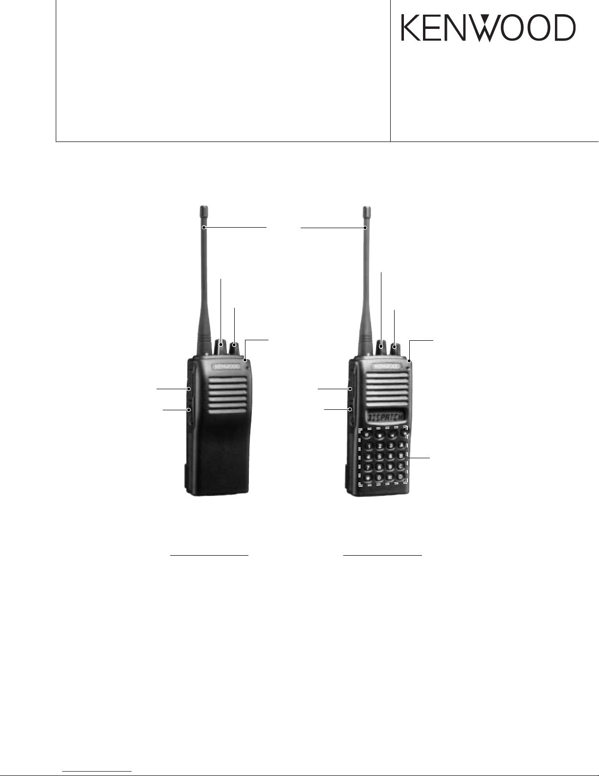
UHF FM TRANSCEIVER
TK-360G/(N)/370G/(N)
SERVICE MANUAL
E VERSIONS
Knob (PTT)
(K29-5334-13)
Knob (Side1)
(K29-5333-13)
Antenna
(T90-0682-05):E, (N)E
(T90-0684-05):E4, (N)E4
Knob (CHANNEL SELECTOR)
(K29-5341-03)
Knob (VOL)
(K29-5332-03)
Cabinet assy
(A02-2391-23)
Knob (PTT)
(K29-5334-13)
Knob (Side1)
(K29-5333-13)
© 2000-4 PRINTED IN JAPAN
B51-8533-00(S) 570
Knob (ENC)
(K29-5331-03)
Knob (VOL)
(K29-5332-03)
Cabinet assy
(A02-2385-23)
TK-360G
M market models are shown.
CONTENTS
GENERAL ......................................................................2
SYSTEM SET-UP .......................................................... 2
OPERATING FEATURES..............................................3
REALIGNMENT ............................................................. 8
DISASSEMBLY FOR REPAIR..................................... 17
CIRCUIT DESCRIPTION .............................................18
SEMICONDUCTOR DATA ..........................................22
DESCRIPTION OF COMPONENTS............................ 24
PARTS LIST.................................................................25
EXPLODED VIEW .......................................................33
PACKING .....................................................................35
Key top (DTMF)
(K29-5330-02)
TK-370G
ADJUSTMENT .............................................................36
PC BOARD VIEWS
DISPLAY UNIT (X54-3250-10)............................... 47
TX-RX UNIT (X57-588X-XX)..................................49
SCHEMATIC DIAGRAM .............................................. 51
BLOCK DIAGRAM ....................................................... 63
LEVEL DIAGRAM ........................................................ 65
KNB-14/KNB-15A (Ni-Cd BATTERY) ..........................66
OPTIONS .....................................................................67
SPECIFICATIONS ................................... BACK COVER
TK-360G/(N)/370G/(N)
GENERAL / SYSTEM SET-UP
INTRODUCTION
SCOPE OF THIS MANUAL
This manual is intended for use by experienced technicians
familiar with similar types of commercial grade
communications equipment. It contains all required service
information for the equipment and is current as of the
publication date. Changes which may occur after publication
are covered by either Service Bulletins or Manual Revisions.
These are issued as required.
ORDERING REPLACEMENT PARTS
When ordering replacement parts or equipment
information, the full part identification number should be
included. This applies to all parts, components, kits, or chassis.
If the part number is not known, include the chassis or kit
number of which it is a part, and a sufficient description of the
required component for proper identification.
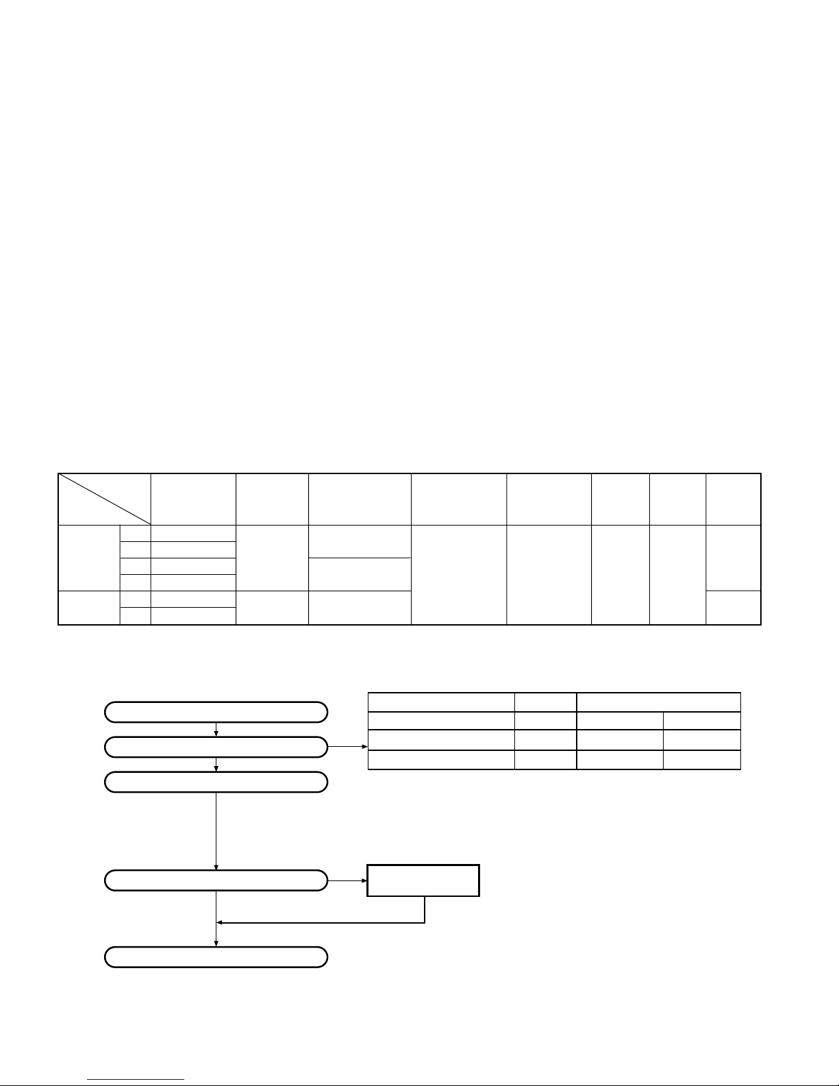
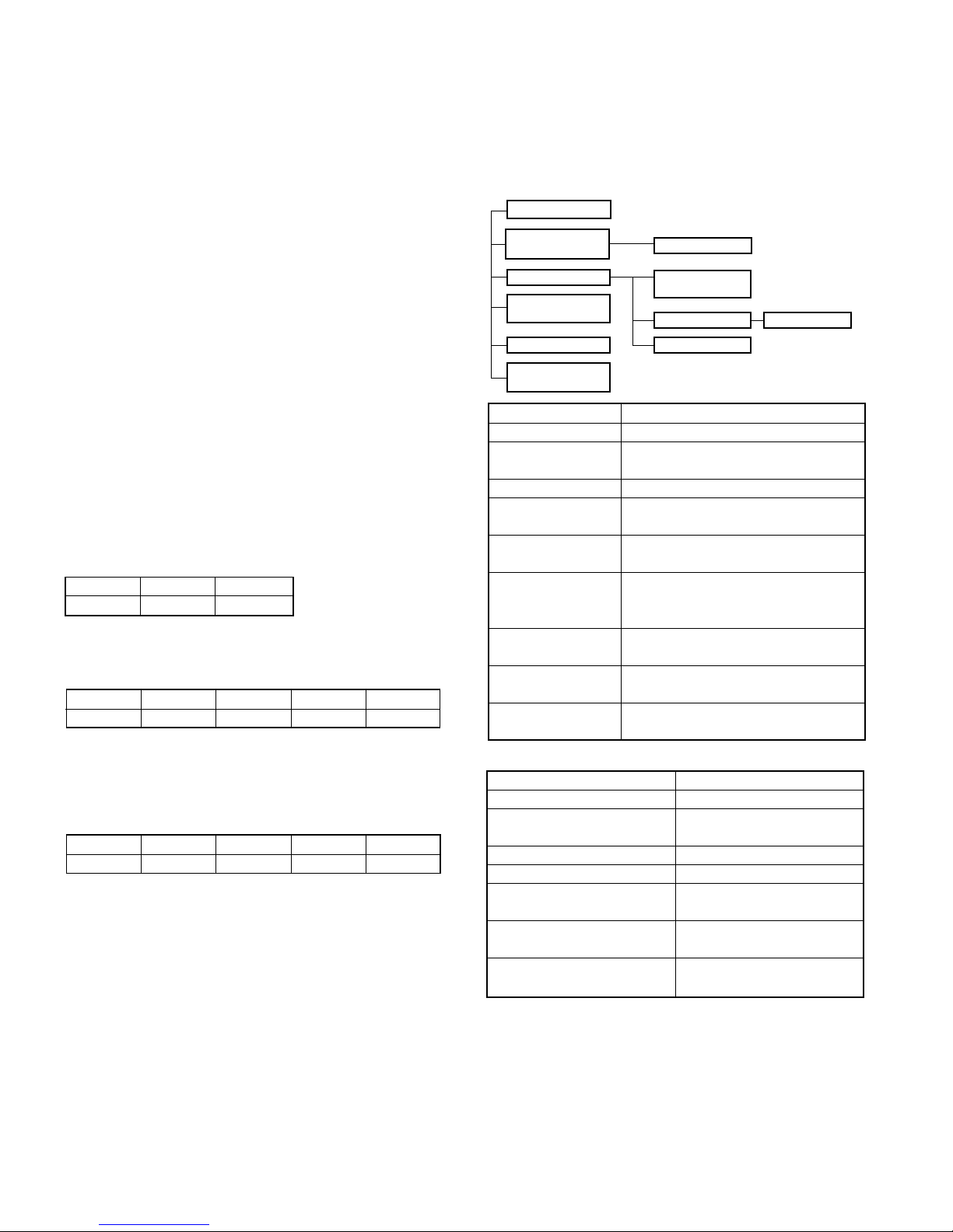
Unit
Model &
destination
TK-360G
TK-370G
(N)E X57-5882-72
(N)E4
(N)E X57-5882-74
TX-RX Unit Display Unit Frequency range Remarks Whip Antenna Charger Battery 16 Key
E X57-5882-71
E4 X57-5882-76
X57-5882-75 LOC : 50.4MHz
E X57-5882-73
– –
X54-3250-10 440~470MHz O
440~470MHz
403~430MHz
PERSONNEL SAFETY
The following precautions are recommended for personnel
safety:
●
DO NOT transmit until all RF connectors are verified secure
and any open connectors are properly terminated.
●
SHUT OFF and DO NOT operate this equipment near
electrical blasting caps or in an explosive atmosphere.
●
This equipment should be serviced by a qualified technician only.
SERVICE
This radio is designed for easy servicing. Refer to the
schematic diagrams, printed circuit board views, and alignment
procedures contained within.
NOTE
The terms “Wide” and “Semi wide” used in this service
manual correspond to “Wide 5K” and “Wide 4K” respectively
that appear in the menu and help texts of the KPG-56D (Field
Programming Unit).
IF1 : 44.95MHz
OOPOP
SYSTEM SET-UP
Choose the type of transceiver
Are you using the speaker microphone?
2
Merchandise received
Transceiver programming
NO
Delivery
Frequency range (MHz) RF power Type
TX/RX 440~470
TX/RX 440~470
TX/RX 403~430
A personal computer (IBM PC or compatible), programming
interface (KPG-22), and programming software (KPG-56D)
are required for programming.
(The frequency, TX power HI/LOW, and signalling data are programmed
for the transceiver.)
YES
KMC-17 or KMC-21
Speaker microphone
(Option)
4.0W
4.0W
4.0W
TK-360G E TK-370G E
TK-360G (N)E TK-370G (N)E
TK-360G E4, (N)E4
TK-360G/(N)/370G/(N)
OPERATING FEATURES
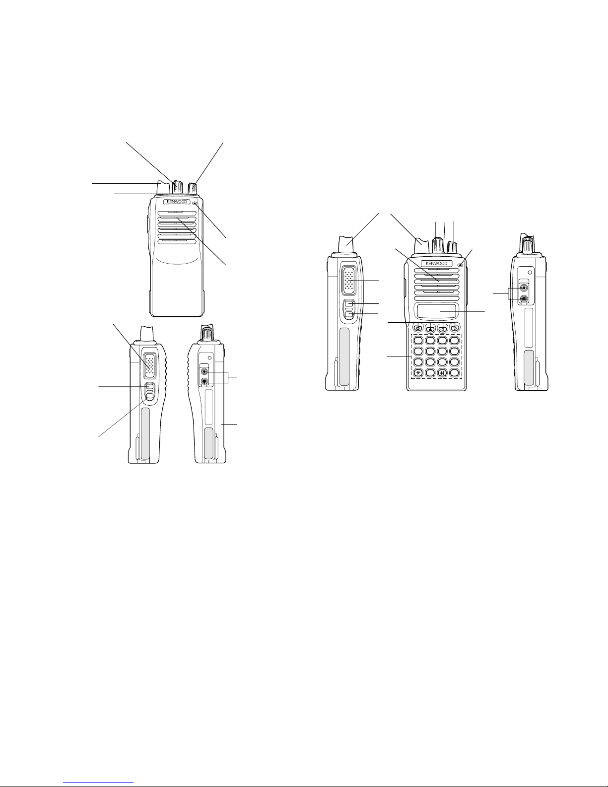
1. Operation Features
• TK-360G
Channel selector
Rotate to select a
channel (1 ~ 8).
Antenna
LED indicator
Lights red while
transmitting. Lights
green while receiving.
Flashes orange while
receiving a 2-Tone or
DTMF signal that
matches the one set
up in your transceiver.
Flashes red when the
battery power is low
while transmitting.
PTT (Push-toTalk) switch
Press this
switch, then
speak into the
microphone to
call a station.
Side 1 key
Press to
activate its
programmable
function.
Side 2 key
Press to
activate its
programmable
function.
Programmable Auxiliary Functions
Side 1 key and Side 2 key can each be programmed
with one of the following auxiliary functions:
• Monitor A (Monitor Unmute–Momentary): Press and
hold the Monitor key to hear background noise. Release
the key to return to normal operation.
• Monitor B (Monitor Unmute–Toggle): Momentarily
press the Monitor key to hear background noise. Press
the key again to return to normal operation.
• Monitor C (Carrier Squelch–Momentary): Press and
hold the Monitor key to deactivate QT, DQT, 2-Tone, or
DTMF signalling. Release the key to return to normal
operation.
• Monitor D (Carrier Squelch–Toggle): Momentarily
press the Monitor key to deactivate QT, DQT, 2-Tone, or
DTMF signalling. Press the key again to return to normal
operation.
• None: No function.
• RF Power Lo: Press the RF Power Lo key to toggle the
output power of a channel between high and low. This
can only be used for channels that have been
programmed with high power. Pressing RF Power Lo
while using a channel programmed with low power
Power switch/
Volume control
Tur n clockwise to
switch ON the
transceiver.
Rotate to adjust
the volume. To
switch OFF the
transceiver, turn
counterclockwise
fully.
Microphone
Speaker
SP/MIC jacks
Connect an
optional speaker/
microphone here.
The transceiver is
shown with the
optional KNB-14
battery pack.
causes an error tone to sound. (When changing a
channel from high to low power, all channels
programmed with high power are changed to low.)
• 2-Tone Encode Select: To transmit using a 2-Tone
code, press the PTT switch and the 2-Tone Encode
Select key, then speak into the microphone in your
normal voice.
Release the PTT switch and 2-Tone Encode Select key
to receive.
• TK-370G
Antenna
ee
ww
e
w
qq
ee
ww
q
qq
Speaker
rr
r
rr
tt
t
tt
yy
y
yy
uu
u
uu
ii
i
ii
0
The transceiver is shown with the optional KNB-14 battery pack.
qq
q Rotary encoder
qq
Microphone
A321
B654
C987
D
oo
o
oo
!0!0
!0
!0!0
Your dealer can program the encoder as either
Group Up/Down or Channel Up/Down (default
setting). Rotate to select a group or channel. Also
rotate to adjust the squelch in Squelch Adjustment
mode.
ww
w LED indicator
ww
Lights red while transmitting. Lights green while
receiving. Flashes orange while receiving a Code
Squelch or a Selective Call code, or a 2-Tone or
DTMF signal that matches the one set up in your
transceiver. Flashes red when the battery power is
low while transmitting.
ee
e Power switch/ Volume control
ee
Turn clockwise to switch ON the transceiver.
Rotate to adjust the volume. To switch OFF the
transceiver, turn counterclockwise fully.
rr
r PTT (Push-to-Talk) switch
rr
Press this switch, then speak into the microphone
to call a station.
tt
t Side 1 key
tt
This is a PF (Programmable Function) key. Press
it to activate its auxiliary function (page 4).
yy
y Side 2 key
yy
This is a PF (Programmable Function) key. Press
it to activate its auxiliary function (page 4).
3

TK-360G/(N)/370G/(N)
OPERATING FEATURES
uu
u
uu
22
33
, •,
2,
3 keys
22
33
°
These are PF (Programmable Function) keys. Press
each key to activate its auxiliary function.
ii
i DTMF keypad
ii
Used for storing and transmitting DTMF numbers.
oo
o SP/MIC jacks
oo
Connect an optional speaker/ microphone here.
!0!0
!0 Display
!0!0
(See page 5.)
Note: The PF k eys are programmed with default functions:
•
Side 1 key: Lamp
•
Side 2 key: Monitor A
•
key: Scan
°
•
key: Scan Del/Add
•
22
•
2
key: Talk Around
22
33
•
3
key: RF Power Lo
33
Programmable Auxiliary Functions
Side 1, Side 2, °, •,
22
2, and
22
33
3 can be programmed
33
with the auxiliary functions listed below.
• Channel Down
• Channel Up
• Display Character
• Group Down
• Group Up
• Home Channel
• Key Lock
• Lamp
• Monitor A (Monitor Unmute–Momentary)
• Monitor B (Monitor Unmute–Toggle)
• Monitor C (Carrier Squelch–Momentary)
• Monitor D (Carrier Squelch–Toggle)
• None
• Redial
• RF Power Lo
• Scan
• Scan Del/Add
• Talk-Around
• 2-Tone Encode Select
2. Programmable keys
The functions the FPU programs to the function keys are
described in the following sections.
1) Channel up/down (TK-370G only)
When the key is pressed each time, the channel number to
be selected is incremented/decremented and repeats if held
for one second or longer.
2) Display character (TK-370G only)
This key switches the LCD display between the group/
channel number and group/channel name.
3) Group up/down (TK-370G only)
When the key is pressed each time, the group number to
be selected is incremented/decremented and repeats if held
for one second or longer.
4) Home Channel (TK-370G only)
Press this key once, the channel switches to the preprogrammed home channel.
5) Key lock (TK-370G only)
When the KEY LOCK switch is held down for one second
or more, keys other than [PTT], [Side1], [Side2], [VOL],
[POWER], and KEY LOCK are locked.
When 12/16 KEY LOCK is set with the FPU, the DTMF
key is locked and when front-panel KEY LOCK is set, the
DTMF key and the [PF] key are locked.
6) Lamp (TK-370G only)
This key illuminates the LCD and keys on the front panel.
When the key is pressed, the LED lamp goes on.
When it is released, the lamp goes off after about five
seconds. If any key is pressed while the LED lamp is on,
the lamp is kept on for five seconds.
7) Monitor
Used to release signalling or squelch when operating in
conventional mode. It is also used to reset option signalling.
8) 2-Tone Encode Select (TK-370G only)
1 Press the key programmed as 2-tone Encode Select.
• A pre-programmed 2-tone code name appears on the
display.
2 Press the key programmed as Rotary encoder to select
you desired 2-tone code name.
3 Press PTT switch and 2-Tone Encode Select key to transmit
and release them to receive.
4
9) Redial (TK-370G only)
Pressing this key when Group/Channel is shown, displays
the previously transmitted DTMF code. Pressing [PTT] at
this time, transmits the code that is currently displayed.
TK-360G/(N)/370G/(N)
OPERATING FEATURES
10) RF power low
Used to temporarily switch transmission output to low power.
Turning the function on enables:
Hi→Low, Low→Low
Key states are backed up, except in the PC mode when
they are reset.
11) Scan (TK-370G only)
Pressing this key starts scanning. Pressing this key again
stops scanning.
12) Scan Del/Add (TK-370G only)
This key switches the currently displayed channel between
"Delete" and "Add".
The "Add" channel is contained in the scan sequence, the
"Delete" channel is not contained. In the scan mode, this key
switches the channel between delete or add, temporarily.
13) Talk Around (TK-370G only)
Press this key, the transceiver uses the receive frequency
and tone for transmission.
The operator can call the other party directly (without repeater).
Press this key again, the talk around function goes off.
14) None
An error operation beep sounds, and no action will occur.
Use this function when the transceiver is required to be
operated more simply.
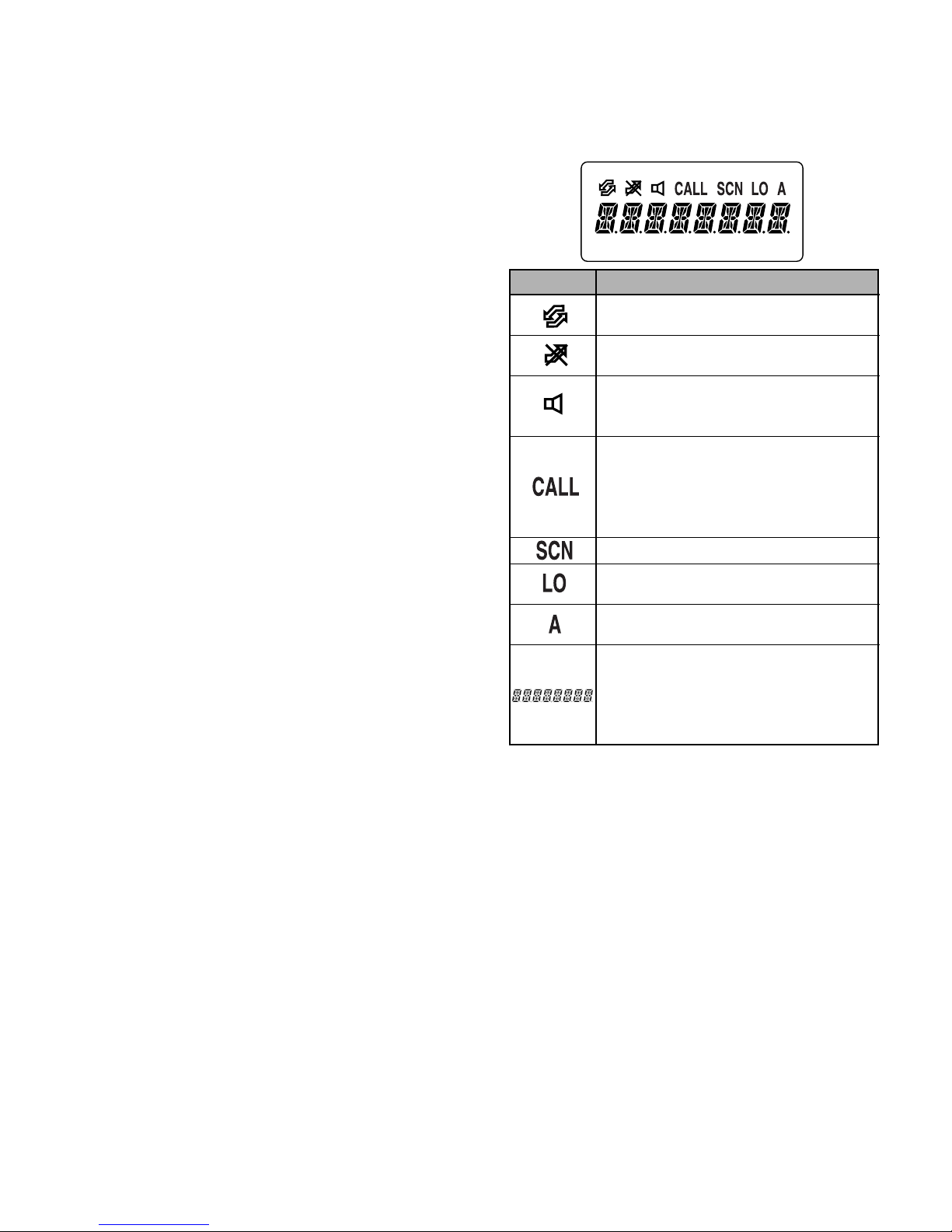
3. Display (TK-370G only)
Icon Description
Not used on this transceiver.
Appears when the selected channel is
busy.
Appears when QT, DQT, DTFM, or 2Tone decoding is deactivated (by
pressing the Monitor key).
Appears when you receive a Code
Squelch, Selective Call, 2-Tone, or
DTMF Signallling call. Also appears
when you transmit using Code Squelch
or Selective Call.
Appears while scanning.
Appears when using low power on the
selected channel.
Appears when the selected channel is
included in the scanning sequence.
Displays the selected channel, the
squelch level, DTMF digits (when
entering digits, confirming digits, or
making a call), and messages received
via Selective Call.
4. Scan Operating (TK-370G only)
1) Scan types
●
Single Group Scan
You can scan all valid (ADD) channels in the displayed group
that can be selected with the group selector.
●
Multiple Group Scan
You can scan all valid (ADD) channels in all valid (ADD)
groups.
2) Scan Start Condition
One or more non-priority channels must be added to all
channels that can be scanned. The transceiver must be in
normal receive mode (PTT off).
When you activate the key programmed to the scan function,
scan starts. The scan icon ("SCN") lights and "SCAN" is
indicated on display.
5

TK-360G/(N)/370G/(N)
OPERATING FEATURES
3) Scan Stop Condition
The scan stops temporarily if the following conditions are
satisfied.
1 The receiving signal matches the signalling code in your
radio that is set by the programming software (KPG-56D).
2 When the monitor key is depressed.
4) Scan Channel Types
1 Priority channel is the most important channel for scan,
and always detects a signal during scan and when the scan
stops temporarily.
2 Non-priority channels detect a signal during scan. For the
channels that can be selected with the group or channel
selector when the scan does not occur, the "A" icon lights.
5) Priority Channel Setting
A priority channel can be set as follows with the programming
software (KPG-56D).
1 Specify a priority channel as a fixed priority channel.
2 Make a selected channel a priority channel.
Specify the initial channel before the operator changes it.
6) Scan Type According to the Priority Channel
1 When no priority channel is set : Only the non-priority
channels are scanned.
If a non-priority channel stops temporarily, it stops until
there is no signal on the channel.
2 When priority channel is set : Either priority channel is
scanned.
If a non-priority channel stops temporarily, a priority channel
signal is detected at certain intervals.
If a priority channel stops temporarily, it stops until there is
no signal on the priority channel.
6 Selected with talkback
The transceiver reverts to the channel before scanning or
the channel that you changed during scan.
8) Scan End
When you reactivate the key programmed to the scan
function during scan mode, scan ends.
The scan icon ("SCN") and "SCAN" or revert channel
(programmable) display goes off.
9) Temporarily Delete/Add
It is possible to delete or add a channel temporarily during
scan. When scan stops on an unnecessary channel, for
example by interference of the other party, press the delete/
add key, then that channel is deleted temporarily and scan will
re-start immediately.
When you would like to add a deleted channel temporarily
to the scan sequence, select the desired (deleted) channel
during scan, and press the delete/add key before scan re-starts.
That channel is added temporarily to the scan sequence.
The temporarily deleted or added channels are returned to
their pre-set delete/add conditions when the transceiver exits
from scan mode.
5. Details of Features
1) Time-out timer
The time-out timer can be programmed in 15 seconds
increments from 15 seconds to 300. If the transmitter is keyed
continuously for longer than the programmed time, the
transmitter is disabled and a warning tone sounds while the
PTT button is held down. The alert tone stops when the PTT
button is released.
7) Revert Channel
The revert channel is used to transmit during scanning and
set by the programming software (KPG-56D).
1 Priority
The transceiver reverts to the priority channel.
2 Priority with talkback
The transceiver reverts to the priority channel.
If you press PTT during a resume timer (dropout delay time,
TX dwell time) or calling, you can transmit on the current
channel to answer to the call however revert channel is set
to priority channel.
After resume time, scan re-starts and the transmission
channel returns to the priority channel.
3 Selected channel
The transceiver reverts to the channel before scanning or
the channel that you changed during scan.
4 Last called channel
The transceiver reverts to the last called channel during
scan.
5 Last used channel
The transceiver reverts to the last used (transmitted)
channel during scan. "Last used" revert channel includes
6
talkback function.
2) Selective Call Alert LED
You can select whether or not the LED on the transceiver
flashes orange when selective call has occurred.
3) PTT ID
PTT ID provides a DTMF ANI to be sent with the PTT button
every time it is used (Begin of TX ID at beginning of
transmission, End of TX ID at end of transmission, or both).
You can program the PTT ID as one of the followings.
Off, BOT (Begin of TX ID), EOT (End of PTT ID), BOTH.
The contents of ID are programmed for each channel.
The transceiver is capable of having ID. The format is
DTMF.
The timing that the transceiver sends the ID is
programmable.
Begin of TX ID (BOT) :Begin of TX ID is sent at the
beginning of transmission.
End of TX ID (EOT) : End of TX ID is sent at the end of
transmission.
Both : Begin of TX ID is sent at the beginning of transmission
and End of TX ID is sent at the end of transmission.
There is also a "PTT ID" setting for each channel.

TK-360G/(N)/370G/(N)
OPERATING FEATURES
4) Battery Warning
This transceiver has a battery warning feature. If low voltage
is detected during transmission, the transceiver warns you by
a flashing red "LED".
When the voltage is detected to be even lower during
transmission, the transceiver stops transmission and warns
you by a flashing red "LED" and a beep.
Please notice "indication" for the battery exchange, charging
time by flashing red LED and beep.
5) "TOT" Pre-Alert
The transceiver has a "TOT" pre-alert timer. This parameter
selects the time at which the transceiver generates a "TOT"
pre-alert tone before the "TOT" is expired.
"TOT" will expire when the selected time passes from the
TOT pre-alert tone.
6) "TOT" Re-Key Time
The transceiver has a "TOT" re-key timer. This timer is the
time you cannot transmit after the "TOT" is exceeded. After
the "TOT" re-key time expires you can transmit again.
7) "TOT" Reset Time
The transceiver has a "TOT" reset timer. This timer is the
minimum wait time allowed during a transmission that will reset
the "TOT" count.
"TOT" reset time causes the "TOT" to continue even after
the PTT is released, unless the "TOT" reset timer has expired.
6. Option Signalling (DTMF/2 tone)
Built-in DTMF decoder is available for option signalling.
Built-in 2-Tone decoder is available for option signalling.
It is possible to use individual call, group call, DBD (Dead
Beat Disable). Note : DBD is only DTMF
Preset operation is triggered when there is match with Option
Signaling.
When Option Signaling matches on a Group Channel where
it is set to Yes, the Option Signaling display flashes and Option
Signaling is canceled. Settings after this will cause "Transpond"
or "Alert" to sound.
Setting the Selective Call Alert LED will cause the LED to
start flashing orange.
Mute or Unmute is triggered by the ID/QT/DQT/Carrier when
option signaling matches (when Option Signal is deactivated
by a transmission).
AND/OR
Option Signaling match conditions can be selected with
AND/OR logic.
Alert/Transpond AF Mute Open
AND
Triggers at match with QT/ Triggers at match with QT/
DQT/ID+DTMF(2tone);Opt
OR
Triggers at match with Triggers only for match with
DTMF(2tone) ; Opt
DQT/ID+DTMF(2tone);
QT/DQT/ID;Signaling
Opt
8) OST (Operator Selectable Tone) (TK-370G K types
only)
The transceiver is capable of having the "OST" function and
16 tone pairs (QT/DQT) with a max 10-digit name for each
tone pair.
9) Clear to Transpond
The transceiver waits for an acknowledgment signal until
the channel become free.
This feature ensures the acknowledgment signal is receive
by another party.
10) Battery Save
This is the automatic battery saver during standby mode
operation. The receiver circuit is turned on and off to conserve
the battery life.
Even if set as OR, there is no Alert/Transpond just with
DTMF.
Even if set as OR, AF mute cannot be canceled just by a
match with DTMF.
In conventional channels not set with QT/DQT, signaling is
a match just by receiving the carrier.
Auto Reset
When Option Signaling matches on a Group channel where
it is set to Yes, Option Signaling is canceled when it matches a
group channel set to Yes.
After Option Signaling matches, Option Signaling can
automatically Reset after a specified time.
Dead Beat Disable
When the D.B.D (Dead Beat Disable) code matches, a
preset operation is performed.
When D.B.D matches on all group channels regardless of
whether Option Signaling = Yes/No, then TX Inhibit or TX RX
Inhibit is activated by the settings performed afterwards. D.B.D
is canceled when the D.B.D. code + "#" is received.
Transpond is always activated when the D.B.D code is a
matches. Alert is not output. An Option Signaling match is not
displayed.
7
TK-360G/(N)/370G/(N)
OPERATING FEATURES / REALIGNMENT
7. Audible user feedback tones (TK-370G
only)
The transceiver outputs various combinations of tones to
notify the user of the transceiver operating state. The main
tones are listed below
The high tone is 1477Hz, the mid tone is 941Hz, and the
low tone is 770Hz.
• Power on tone
This tone is output when the transceiver is turned on. (The
high tone is output for 500ms.)
• Alert tone
This tone is output when the transceiver is in TX inhibition
for TOT, battery warning and PLL unlocked. It is output until
the PTT button is released. (The 697Hz tone is output.)
• Busy Tone
This informs the user of a busy channel lock out
• Group Call Tone
The group call tone informs the user of a group call in DTMF/
2 Tone Option Signaling. This tone repeats 7 times.
770Hz 770Hz
30ms 30ms 30ms
• Individual Tone
Individual tone is issued on receiving selective call by DTMF/
2 Tone Option Signaling.
2000Hz 2000Hz 2000Hz
100ms 100ms 100ms 100ms 100ms
• Pre Alert tone
Informs the user when nearing transmit inhibit (transmit
cutoff) time due to TOT.
The Pre Alert Tone is issued from the time set for TOT Pre
Alert until the TOT triggers.
1633Hz 1633Hz 1633Hz
50ms 50ms 50ms 50ms 50ms
REALIGNMENT
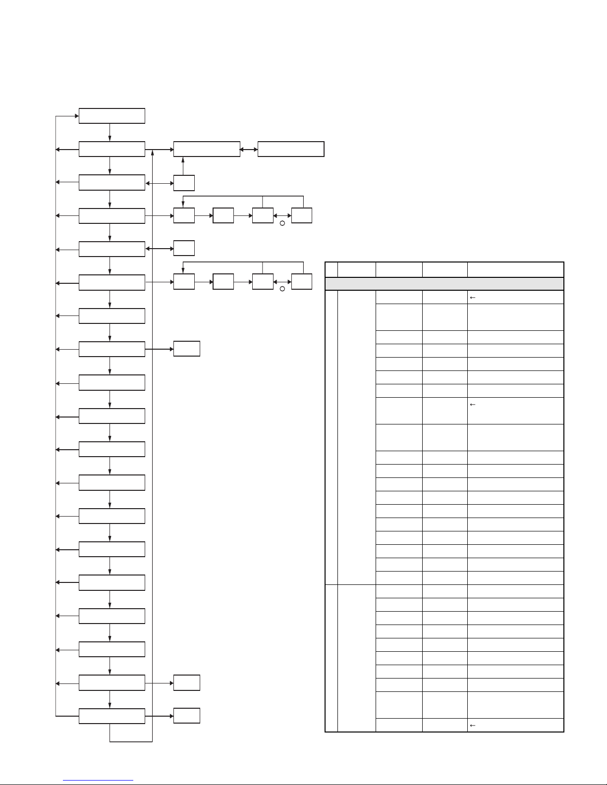
1. Modes
User mode
Panel test mode
(TK-370G only)
PC mode
Firmware
programming mode
Clone mode
Self programming
mode (TK-370G only)
Mode Function
User mode For normal use.
Panel test mode Used by the dealer to check the
Panel tuning mode Used by the dealer to tune the radio.
PC mode Used for communication between the
Data programming Used to read and write frequency data
mode
PC test mode Used to check the radio using the PC.
Firmware program- Used when changing the main
ming mode program of the flash memory.
Clone mode Used to transfer programming data
Self programming Frequency, signalling and features.
mode
Panel tuning mode
Data programming
mode
PC test mode
Checksum
fundamental characteristics.
radio and PC (IBM compatible).
and other features to and from the radio.
This feature is included in the FPU.
See panel tuning.
from one radio to another.
PC tuning mode
2. How to Enter Each Mode
Mode Operation
User mode Power ON
Panel test mode
PC mode Received commands from PC
Panel tuning mode [Panel test mode]+[°]
Firmware programming mode
Clone mode [Side1]+[3]+Power ON
Self programming mode [Side1]+[
[2]+Power ON (Two seconds)
(TK-370G only)
[Side1]+[Side2]+Power ON
(Two seconds)
(Two seconds)
]+Power ON
(Two seconds) (TK-370G only)
•
8
3. For the panel Test Mode (TK-370G only)
For the setting method, refer to ADJUSTMENT.
3-1. For the panel Tuning Mode
For the setting method, refer to ADJUSTMENT.
TK-360G/(N)/370G/(N)
REALIGNMENT
4. Checksum
Executing this function, "TUNING" appears on the display
of TK-370G while calculating the checksum .
When the calculation is completed, the display returns to
normal and PC displays the checksum of the radio.
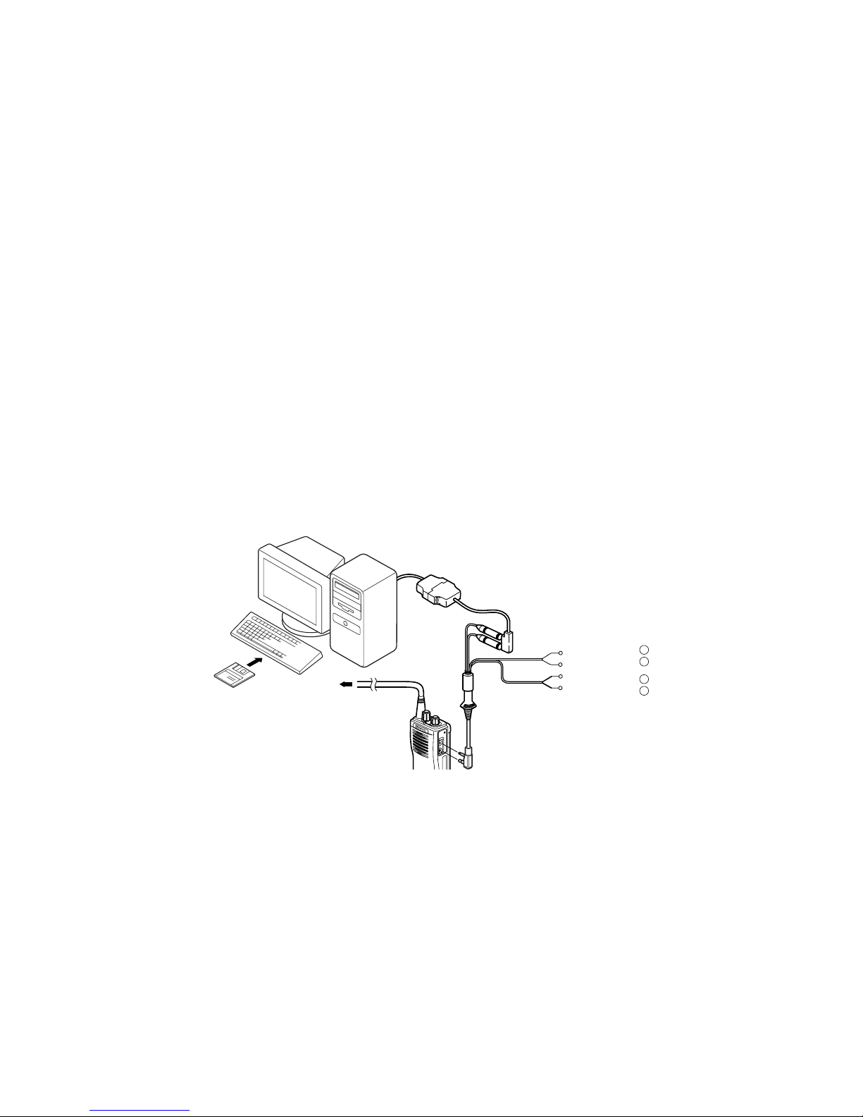
5. PC Mode
5-1. Preface
The TK-360G/370G transceiver is programmed using a
personal computer, a programming interface (KPG-22) and
programming software (KPG-56D).
The programming software can be used with an IBM PC or
compatible. Figure 1 shows the setup of an IBM PC for
programming.
5-2. Connection procedure
1. Connect the TK-360G/370G to the personal computer with
the interface cable.
2. When the POWER is switched on, user mode can be
entered immediately. When the PC sends a command, the
radio enters PC mode.
When data is transmitted from transceiver, the red LED blink.
When data is received by the transceiver, the green LED blinks.
IBM-PC
Notes:
• The data stored in the personal computer must match model
type when it is written into the flash memory.
• Change the TK-360G/370G to PC mode, then attach the
interface cable.
5-3. KPG-22 description
(PC programming interface cable: Option)
The KPG-22 is required to interface the TK-360G/370G to
the computer. It has a circuit in its D-subconnector (25-pin)
case that converts the RS-232C logic level to the TTL level.
The KPG-22 connects the SP/MIC connector of the TK360G/370G to the computers RS-232C serial port.
5-4. Programming software description
The KPG-56D programming disk is supplied in 3-1/2” disk
format. The software on this disk allows a user to program the TK360G/370G radios via a programming interface cable (KPG-22).
5-5. Programming with IBM PC
If data is transferred to the transceiver from an IBM PC with
the KPG-56D, the destination data (basic radio information) for
each set can be modified. Normally, it is not necessary to modify
the destination data because their values are determined
automatically when the frequency range (frequency type) is set.
The values should be modified only if necessary. Data can
be programmed into the flash memory in RS-232C format via
the universal connector.
KPG-56D installation manual part No. : B62-1153-XX
KPG-56D
RF Power meter
or SSG
6. Firmware Programming Mode
6-1. Preface
Flash memory is mounted on the TK-360G/370G. This
allows the TK-360G/370G to be upgraded when new features
are released in the future. (For details on how to obtain the
firmware, contact Customer Service.)
6-2. Connection procedure
Connect the TK-360G/370G to the personal computer (IBM
PC or compatible) with the interface cable (KPG-22).
(Connection is the same as in the PC Mode.)
KPG-22
+
SP
}
+
MIC
}
-
Tuning cable
(E30-3216-05)
Gray
Gray/Black
1.5D-XV Lead wire
Gray-XV Shield wire
Fig. 1
6-3. Programming
1. Start up the programming software (KPG-56D), select
"firmware program" in the "Program" item, and press the
Return key on your personal computer. This starts up the
firmware programmer.
2. The top screen is displayed. Press any key to advance to
the next screen.
3. Set the communications speed (normally, 57600 bps) and
communications port in the Setup item.
4. Set the firmware to be updated by File select (=F1).
5. Hold down the [Side1] and [Side2] switches on the TK-360G/
370G, and press the power switch.
When the [Side1] and [Side2] switches are held down for
two seconds, "PROG 576" appears on the display and
the LED lights orange. When "PROG 576" is displayed,
release the switches. (TK-370G only)
9

TK-360G/(N)/370G/(N)
REALIGNMENT
6. Check the connection between the TK-360G/370G and the
personal computer, and make sure that the TK-360G/370G
is in Program mode.
7. Press F10 on the personal computer. A window opens on
the display to indicate the writing progress. When the TK360G/370G begins to receive data, the LED lights green.
8. When data is received successfully, a checksum appears
on the display.
(Since the TK-360G does not have a display, check the
checksum with the FPU (KPG-56D).)
9. If you want to continue programming other TK-360G/
370Gs, repeat steps 5 to 8.
Notes:
●
To start the Firmware Programmer from KPG-56D, the Fpro
path must be set up by the KPG-56D Setup.
●
This mode cannot be entered if the Firmware Programming
mode is set to Disable in the Programming software (KPG-56D).
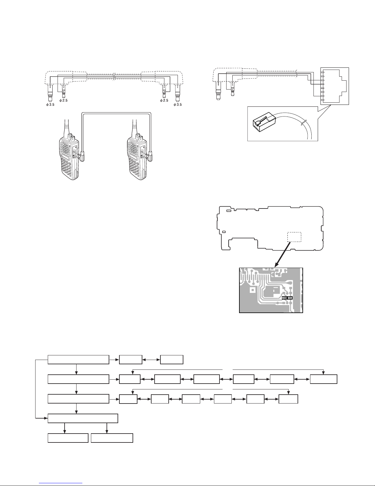
7. Clone Mode
Programming data can be transferred from one radio to
another by connecting them via their SP/MIC connectors. The
operation is as follows (the transmit radio is the master and
the receive radio is the slave).
●
When programming the firmware, it is recommend to copy
the data from the floppy disk to your hard disk before you
update the radio firmware.
Directly copying from the floppy disk to the radio may not
work because the access speed is too slow.
6-4. Function
1. If you press the [Side2] switch while "PROG XXX" is
displayed, the checksum is displayed. If you press the
[Side2] switch again (while the checksum is displayed),
"PROG XXX" is redisplayed.
2. A transmission speed can be selected by pressing the [Side1]
switch while "PROG XXX" is displayed.
19200 bps: The LED flashes green and red alternately.
38400 bps: The LED flashes orange.
57600 bps: The LED lights orange.
Note:
Normally, write in the high-speed mode.
1. Turn the master TK-370G power ON with the [Side1]+[3]
key held down. The TK-370G displays "
2. Power on the slave TK-360G/370G.
3. Connect the cloning cable to the SP/MIC connectors on
the master and slave.
4. Press the [
"
CLONE ". The data of the master is sent to the slave.
While the slave is receiving the data, "-PC-" is displayed.
When cloning of data is completed, the master displays
"END", and the slave automatically operates in the User
mode. The slave can then be operated by the same program
as the master.
Slave TK-360G TK-360G TK-360G TK-360G TK-862 TK-862
Master
TK-370G
E
TK-370G
(N)E
] key on the master while the master displays
°
E (N)E E4 (N)E4 E (N)E
TK-370G TK-370G
E (N)E
OK N/A N/A N/A OK N/A
N/A OK N/A N/A N/A OK
CLONE ".
5. The other slave can be continuously cloned. When the [
key on the master is pressed while the master displays
"END", the master displays "
operation in steps 2 to 4.
Note: You can clone the programmed data between the
transceiver listed below.
Frequency version must be same.
Use the new clonig cable for TK-360G/370G.
You cannot use the old cloning cable for TK-360/370.
]
°
CLONE ". Carry out the
10
TK-360G/(N)/370G/(N)
REALIGNMENT
Cloning cable parts No.
E30-3410-05 (TK-370G→TK-360G/370G)
PTT/RXD
GND
REMOTE/TXD
Cloning cable
Fig. 2
8. Self Programming Mode (TK-370G)
Write mode for frequency data and signalling etc. Mainly
used by the person maintaining the user equipment.
8.1 Self programming mode setting
Remove D17 from the TX-RX unit (Figure 3) (K, K4, E, (N)E
models only). Hold down the [Side1]+[●] switches and turn
the power switch on.
When the self programming mode is entered, [SELF]
appears on the display. The mode changes automatically
to Model Select Mode and “PORTABLE” is displayed in
about one second.
PTT/RXD
E30-3411-05 (TK-370G→TK-860G/862G)
1
GND
REMOTE/TXD
8
8
1
X57-588X
Compoent Side
MBL
PSB
GND
PTT/RXD
ME
MIC
REMOTE/TXD
CM
Note :
This mode (self programming mode) cannot be set when it
has been disabled with the FPU.
Note :
Self Programming is disabled if "a Trunking Board is
installed in this Radio" is selected in FPU.
●
Flow Chart
Radio type Portable Mobile
[2]
Radio Band & Channel Type
VHF 8CH
[CH]
M models only M models only
VHF 16CH
[2]
Frequency Version
[3]
Self programming mode
Channel set mode
[2]
[Side2]
VHF F1
[Side1]
Function set mode
VHF F2 UHF F1 UHF F3
[CH][CH]
Note :
IF the radio type of TK-370G was temporally set to "Mobile"
for the cloning purposes, "UNPROG" is displayed (at User
D17
Fig. 3
[CH]
VHF 128CH UHF 16CH UHF 128CH
[CH][CH]
UHF F2
[CH]
Mode) when the TK-370G is turned on.
In this case, please set the radio type back to "Portable" at
Model Select Mode menu.
[CH]
[CH]
UHF 8CH
[CH]
[CH]
[CH]
UHF F4
[CH]
Frequency version
selection that
matches Radio
Band and Channel
Type appears.
11
TK-360G/(N)/370G/(N)
REALIGNMENT
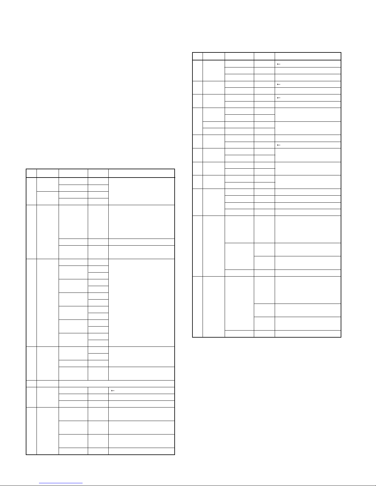
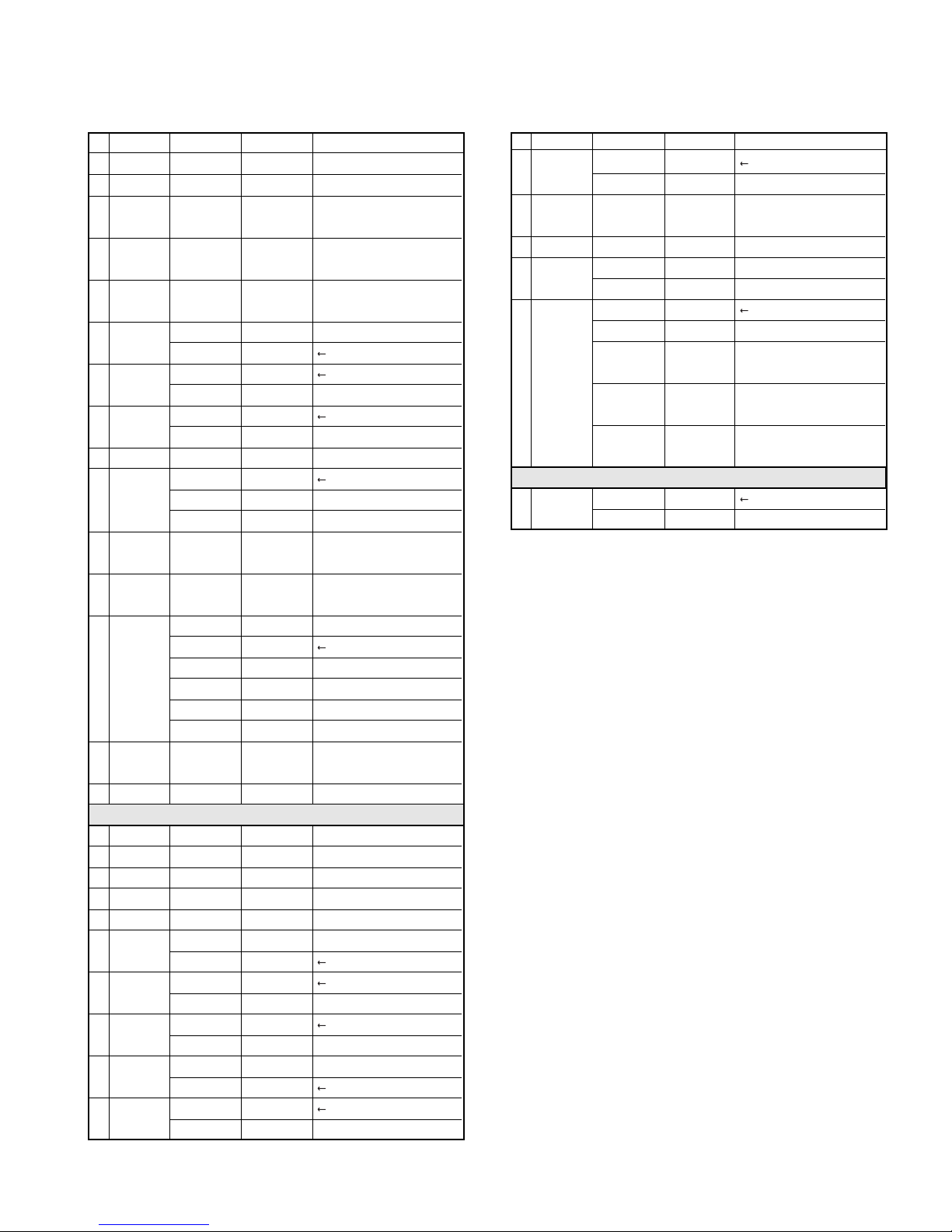
8-2. Channel Setting Mode
This is a mode for making channel settings with the panel
keys without using the FPU.
Pressing [Side2] when "SELF" is displayed, sets Channel
Setting Mode.
Select an item set using [3] then change the selection with
the encoder.
The data displayed using [2] is stored in the memory and
then proceeds to the next item. Pressing [3] proceeds to
the next item without storing it in the memory.
Press [Side2] to set the display to "SELF" and return to reset
(default) status.
All channel data is cleared when pressing [2] key with the
blank RX frequency.
No. Function Choices Display Remarks
Select
Channel
Select
Group
1
RX frequency
2
Rx Signaling
3
TX frequency
4
TX Signaling
5
Option Signaling OFF
6ID
1-128
1-128
Step 2.5kHz-1MHz
Blank
100.0000-
550.0000MHz 50Hz digit (On=5; Off=0).
OFF ————[Side1
QT 67.0-250.3Hz
(EIA Mode)
QT 67.0-250.3Hz
(0.1Hz Step Mode)
DQT 000-777 (Normal)
(1 Step Mode)
DQT 023-754 (Normal)
(Standard Table Mode)
DQT 000-777 (Inverse)
(1 Step Mode)
DQT 023-754 (Inverse)
(Standard Table Mode)
Step 2.5kHz-1MHz
Blank
100.0000-
550.0000MHz
DTMF
2-TONE
0009999999999 (about 0.5 seconds)
Blank ————
_1-_1._
_1-128._
_1.-_1_
128.-_1_
STP_250
STP_1000
R.
R.100.0000
QT_67.0_
QT_250.3_
QT_67.0*
QT_250.3*
DQT000N*
DQT777N*
DQT023N
DQT754N
DQT000I*
DQT777I*
DQT023I
DQT754I
STP_250
STP_1000
T. ————
T.100.0000
Same as RX signaling.
NONE____
DTMF____
2TONE___
___ID___
12345678
——987 Display when a code is input
[3] : Group selection/
Channel selection change
Display when an item is selected
or when a step is changed
(about 0.5 seconds)
[•] Step change
UHF : 5.0,6.25kHz,1MHz,Step
————
[Side1] : Freq On/Blank switching
The rightmost dot indicates
] : Off/QT/DQT switching
[•] : Mode switching
[°] :
Normal/Inverse
switching
Same as RX frequency.
Default
Display when an item is selected
Display of the current setting
(If it is 8 or more digits, scroll it.)
(Input it with DTMF key.)
[Side1] : Data clear
No. Function Choices Display Remarks
7
Busy Channel
Lockout
8
Beat shift
9
RF Power
10
Wide/Narrow
Wide 5K
Wide 4K
11
Scan
Delete/ADD
12
Priority
Channel
13
Home Channel
14
Compander
15
PTT ID
16
Begin of
TX ID
17
END of
TX ID
NO
Type 1
Type 2
No
Yes
High Power
Low Power
Wide WIDE_
Narrow
Wide -W5K
Semiwide -W4K
DELETE
ADD
No
Yes
No
Yes
No
Yes
OFF
Begin of TX
End of TX
Both
0009999999999999999
Blank
0009999999999999999
Blank ————
BCL_NO__
BCL_1___
BCL_2___
SHFT_NO_
SHFT_YES
PWR_H___
PWR_L___
NARROW_
SCAN_DEL
SCAN_ADD Default
P.CH_NO__ Not used when (Scan) Priority is not Fixed.
P.CH_YES_
H.CH_NO__
H.CH_YES_
COMP_NO_
COMP_YES
P.ID_OFF
P.ID_1
P.ID_2
P.ID_3
_BOT_ID_
12345678
——987
————
_EOT_ID_
12345678
——987
Default
BCL_YES for K, K4, E, (N)E type
N/A for K, K4, E, (N)E type
Default
Default
K, K4, M, M4, destination only
E destination only
Not used for TK-360G
Not used when Home Channel is
not set in Key Assignment.
Not used when Wide is selected.
Not valid if Dial ID =Disable and
PTT ID=OFF, or EOT is set.
Display when an item is selected
(about 0.5 seconds)
Display of the current setting
(If it is 8 or more digits, scroll it.)
Display when a code is input
(Input it with DTMF key.)
[Side1] : Data clear
Not valid if Dial ID=Disble and
PTT ID=OFF, or BOT is set.
Display when an item is selected
(about 0.5 seconds)
Display of the current setting
(If it is 8 or more digits, scroll it.)
Display when a code is input
(Input it with DTMF key.)
[Side1] : Data clear
12
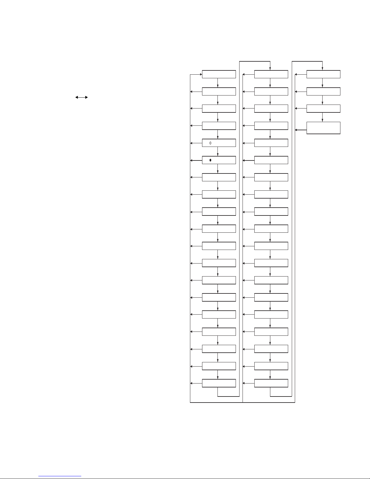
●
Flow Chart
Channel Setting Mode
Self programming mode
TK-360G/(N)/370G/(N)
REALIGNMENT
8-3. Function Setting Mode
This is a mode for using the panel keys to make function
settings without using the FPU, that operate on all channels.
ID
PTT ID
[Side2]
[2]
[2]
[Side1]
[2]/[3]
[Side1]
[2]/[3]
[Side1]
[2]/[3]
[Side1]
[2]/[3]
[2]/[3]
[Side1]
[2]/[3]
[2]/[3]
[2]/[3]
[2]/[3]
[2]/[3]
[2]/[3]
Not used when (Scan) Priority is not Fixed.
[2]/[3]
Not used when Home Channel is not set in key Assignment.
[2]/[3]
[2]/[3]
[2]/[3]
[Side1]
[2]/[3]
[Side1]
[2]/[3]
Channel delete
OFF
OFF
[Side1]
OFF
OFF QT DQT N DQT I
[Side1]
Data clear
Not valid if Dial ID=Disable
Data clear
and PTT ID=off, or EOT is set.
Not valid if Dial ID=Disable
Data clear
and PTT ID=off, or BOT is set.
[Side2]
Channel set mode Channel selection
[Side2]
[Side2]
[Side2]
[Side2]
[Side2]
[Side2]
[Side2]
[Side2]
[Side2]
[Side2]
[Side2]
[Side2]
[Side2]
[Side2]
[Side2]
[Side2]
[Side2]
RX frequency
RX signaling
TX freguency
TX signaling
option signaling
Busy channel lockout
Best Shift yes/no
RF Power High/Low
Wide/Narrow
Scan delete/add
Priority channel
Home channel
Compander yes/no Not used when Wide is selected.
Begin of TX ID
End of TX ID
Group selection
[3]
[Side1]
QT DQT N DQT I
[Side1]
[Side1]
[ ]
[Side1]
[ ]
Pressing the [Side1] when "SELF" is displayed, sets the
Function Setting Mode.
Select an item set using [3] then change the selection with
the encoder.
The data displayed using [2] is stored in the memory and
then proceeds to the next item. Pressing [3] proceeds to
the next item without storing it in memory.
Press [Side1] to display "SELF" and return to reset (default)
status.
Function Setting Mode
No.
Function Choices Display Remarks
Function Key
1
[Side1] No Function
Talk Around
LAMP_OFF Default (TK-360G)
LAMP_3
* TK-360G cannot be selected.
K, M and E destinations only
Display Character
Home Channel
Channel Down
Channel Up LAMP_9
Keylock LAMP_10
LAMP_5
LAMP_7
LAMP_8
* TK-360G cannot be selected.
* TK-360G cannot be selected.
* TK-360G cannot be selected.
* TK-360G cannot be selected.
* TK-360G cannot be selected.
Lamp LAMP_11 Default(TK-370G)
* TK-360G cannot be selected.
2-Tone Encode
LAMP_16
Select
Monitor A LAMP_17
Monitor B LAMP_18
Monitor C LAMP_19
Monitor D LAMP_20
RF Power Low
Scan LAMP_22
Scan DEL/ADD
Group Down
Group Up LAMP_25
Redial LAMP_28
LAMP_21
LAMP_23
LAMP_24
* TK-360G cannot be selected.
* TK-360G cannot be selected.
* TK-360G cannot be selected.
* TK-360G cannot be selected.
* TK-360G cannot be selected.
2 [Side2] No Function MON_OFF
Talk Around MON_3
Display Character
Home Channel
Channel Down
MON_5
MON_7
MON_8
Channel Up MON_9
Keylock MON_10
Lamp MON_11
2-Tone Encode
MON_16
* TK-360G cannot be selected.
* TK-360G cannot be selected.
* TK-360G cannot be selected.
* TK-360G cannot be selected.
* TK-360G cannot be selected.
* TK-360G cannot be selected.
* TK-360G cannot be selected.
Select
MONitor A MON_17 Default
13

TK-360G/(N)/370G/(N)
REALIGNMENT
No.
Function Choices Display Remarks
2 [Side2] MONitor B MON_18
MONitor C MON_19
MONitor D MON_20
RF Power Low
Scan MON_22
Scan DEL/ADD
Group Down
Group Up MON_25
Redial MON_28
3
[°]
TK-370G
No Function KEY1_OFF
only Talk Around KEY1_3
Display Character
Home Channel
Channel Down
Channel Up KEY1_9
Keylock KEY1_10
Lamp KEY1_11
2-Tone Encode
Select
Monitor A KEY1_17
Monitor B KEY1_18
Monitor C KEY1_19
Monitor D KEY1_20
RF Power Low
Scan KEY1_22
Scan DEL/ADD
Group Down
Group Up KEY1_25
Redial KEY1_28
4
[•]
TK-370G
No Function KEY2_OFF
only
Talk Around KEY2_3
Display Character
Home Channel
Channel Down
Channel Up KEY2_9
Keylock KEY2_10
Lamp KEY2_11
2-Tone Encode
Select
Monitor A KEY2_17
Monitor B KEY2_18
Monitor C KEY2_19
Monitor D KEY2_20
RF Power Low
Scan KEY2_22
Scan DEL/ADD
Group Down
MON_21
* TK-360G cannot be selected.
MON_23
MON_24
KEY1_5
KEY1_7
KEY1_8
KEY1_16
KEY1_21
KEY1_23 Default
KEY1_24
KEY2_5
KEY2_7
KEY2_8
KEY2_16
KEY2_21
KEY2_23
KEY2_24
* TK-360G cannot be selected.
* TK-360G cannot be selected.
* TK-360G cannot be selected.
* TK-360G cannot be selected.
No.
Function Choices Display Remarks
4
[•]
TK-370G
Group Up KEY2_25
only
5[2]TK-370G
only Talk Around KEY3_3
6
[3]
only Talk Around KEY4_3
7 [CH]
8
Power On Tone
9
Control Tone
Redial KEY2_28
No Function KEY3_OFF
Display Character
Home Channel
Channel Down
Channel Up KEY3_9
Keylock KEY3_10
Lamp KEY3_11
2-Tone Encode
Select
Monitor A KEY3_17
Monitor B KEY3_18
Monitor C KEY3_19
Monitor D KEY3_20
RF Power Low
Scan KEY3_22
Scan DEL/ADD
Group Down
Group Up KEY3_25
Redial KEY3_28
TK-370G
No Function KEY4_OFF
Display Character
Home Channel
Channel Down
Channel Up KEY4_9
Keylock KEY4_10
Lamp KEY4_11
2-Tone Encode
Select
Monitor A KEY4_17
Monitor B KEY4_18
Monitor C KEY4_19
Monitor D KEY4_20
RF Power Low
Scan KEY4_22
Scan DEL/ADD
Group Down
Group Up KEY4_25
Redial KEY4_28
Channel Up/Down
Group Up/Down
No Function
YES/NO
YES/NO CNTT_YES Default:YES
KEY3_5
KEY3_7
KEY3_8
KEY3_16
KEY3_21 Default
KEY3_23
KEY3_24
KEY4_5
KEY4_7
KEY4_8
KEY4_16
KEY4_21 Default
KEY4_23
KEY4_24
CH_UP/DN Default
GR_UP/DN
KNOB_OFF
Optional Feature
PONT_YES
Default
Default:YES
14
No.
Function Choices Display Remarks
10
Warning Tone
11
Time Out Timer
TOT
12
Pre-Alert Time
TOT
13
Rekey Time
TOT OFF1-15/
14
Reset Time
15
Clear to Transpond
(BCL for Transpond)
16
Battery Save
17 Signaling OR SIG__OR Default
18
Squelch Level
19 Priority None PRI_NONE
Lock Back
20
Time A
Lock Back
21
Time B
22
Revert
Channel
Dropout
23
Delay Time
24
Dwell Time
25
Digit Time
26
Inter Digit Time
27
First Digit Time
28
First Digit Delay
29
Rise Time with QT
30 DIAL ID Enable DID_ENA
31
No.of
DTMF Key
32
DTMF Hold Time
33
Store and Send
34
D Key
Assignment
YES/NO
OFF,15-300/15s Step
OFF,1-10/
1s Step
OFF1-60/
1s Step
1s Step
YES CTT_YES
NO CTT_NO
ON BATT_ON Default
OFF BATT_OFF
AND SIG_AND
0-9/1 Step SQL__5 Default;5
Fixed PRI_FIX_
Selected PRI_SEL_
0.5-5.0/0.05 LBA_500 Default:500ms Cannot be
0.5-5.0/0.05 LBB_2000 Default:2000ms Cannot
Selected REV_SEL
Last Called REV_L/C_ Default
Last Used REV_L/U_
Selected + Talk Back
Priority REV_PRI_
Priority + Talk Back
0-300/1s DODT___3 Default;3s
0-300/1s DWL___3 Default;3s
50-200/10ms
50-200/10ms
50-200/10ms
100-1000/50ms
100-1000/50ms
Disable DID_DIS Default
12Key NODK_12 Default
16Key NODK_16
ON DHT__ON Default
OFF DHT__OFF
Enable SAS_ENA
Disable SAS_DIS Default
D Code
1-16/1s DKA_16__
WART_YES
TOT_60 Default:60s
TOTP_PFF
TOTK_OFF
TOTS_OFF
REV_S/T_
REV_P/T_
DTMF
DIGT__50 Default;50ms
IDT___50 Default;50ms
FDT___50 Default;50ms
RIST_100 Default;100ms
RTWQ_100
DKA_D_CD Default
Default:YES
Cannot be set when TOT is OFF.
Default:OFF
Cannot be set when TOT is OFF.
Default:OFF
Cannot be set when TOT is OFF.
Default:OFF
Default
Default
set when Priority = none.
be set when Priority = none
Default;100ms
TK-360G/(N)/370G/(N)
REALIGNMENT
No.
Function Choices Display Remarks
35
DTMF
Signaling
36
Inter Mediaate
Code
37
Group Code
38 Auto Rest OFF ART_OFF_
Time 1-15/1s ART__10 Default;10s
39
Call Alert/
Transpond
40
Panel Test/panel
Tuning MODE
.
Code SQ
SEL CALL
0-9,A-D,*,# IMC__#_
A-D,*,#
OFF CA/T_OFF Default
Call Alert CA/T_C/A
Transpond CA/T_T/A
(Call Alert)
Transpond CA/T_T/I
(ID Code)
Transpond CA/T_T/T
(Transpond Code)
Enable PTM_ENA Default (Not used for TK-360G.)
Disable PTM_DIS
DTMS_CSQ Default
DTMS_SEL
GPCD_FF_ Default;OFF
Others
TK-370G only
Default: # (Can be set only when
DTMF signaling = SEL CALL.)
15
TK-360G/(N)/370G/(N)
REALIGNMENT
8-4. Memory Reset Mode
This mode is used to clear data for functions that can be set
in Self Programming Mode or to return to reset values (default).
Pressing [
"CANCEL".
Turning the encoder alternately switches the display
between "CANCEL" "READY".
Pressing [
sets the display to "CLEAR".
Pressing [
Pressing [
to "SELF" without resetting the data.
When the memory is reset, mode data and model data are
not reset.
The TK-360G cannot reset the memory.
] when "SELF" is shown, sets the display to
°
] when "READY" is shown, clears the data and
°
] again, returns the display to "SELF".
°
] when "CANCEL" is shown, returns the display
°
●
Function Setting Mode
Flow Chart
Self programming mode
[Side1]
Function set mode
[Side1]
[Side1] key function
[Side1]
[MON] key function
[Side1]
[ ] key function
[Side1]
[ ] key function
[Side1]
[2]/[3]
[2]/[3]
[2]/[3]
[Side1]
[Side1]
[Side1]
Look back time A
[Side1]
Look back time B
[Side1]
[Side1]
Dropout delay time
Squelch level
[2]/[3]
Priority
[2]/[3]
[2]/[3]
[2]/[3]
Revert channel
[2]/[3]
[Side1]
[Side1]
[Side1]
[Side1]
Group code
Auto reset time
Call alert/Transpond
Panel test/Panel tuning
mode
[2]/[3]
[2]/[3]
[2]/[3]
[Side1]
[2]
key function
[Side1]
[3]
key function
[Side1]
[CH]
key function
[Side1]
Power on tone yes/no
[Side1]
Contorol tone yes/no
[Side1]
WArning tone yes/no
[Side1]
Time Out Timer
[Side1]
T.O.T. Pre-alert time
[Side1]
T.O.T. Rekey time
[Side1]
T.O.T. Reset time
[Side1]
Clear to Transpond
[Side1]
Battery Save on/off
[Side1]
Signaling
[2]/[3]
[2]/[3]
[2]/[3]
[2]/[3]
[2]/[3]
[2]/[3]
[2]/[3]
[2]/[3]
[2]/[3]
[2]/[3]
[2]/[3]
[2]/[3]
[2]/[3]
[2]/[3]
[Side1]
[Side1]
[Side1]
[Side1]
[Side1]
[Side1]
[Side1]
[Side1]
[Side1]
[Side1]
[Side1]
[Side1]
[Side1]
[2]/[3]
Dwell time
[2]/[3]
Digit time
[2]/[3]
Inter digit time
[2]/[3]
First digit time
[2]/[3]
First digit delay
[2]/[3]
Rise time with QT
[2]/[3]
Dial ID
[2]/[3]
No. of DTMF key
[2]/[3]
DTMF hold time
[2]/[3]
Store & Send
[2]/[3]
D key assignment
[2]/[3]
DTMF signaling
[2]/[3]
Inter mediate code
[2]/[3]
16
TK-360G/(N)/370G/(N)
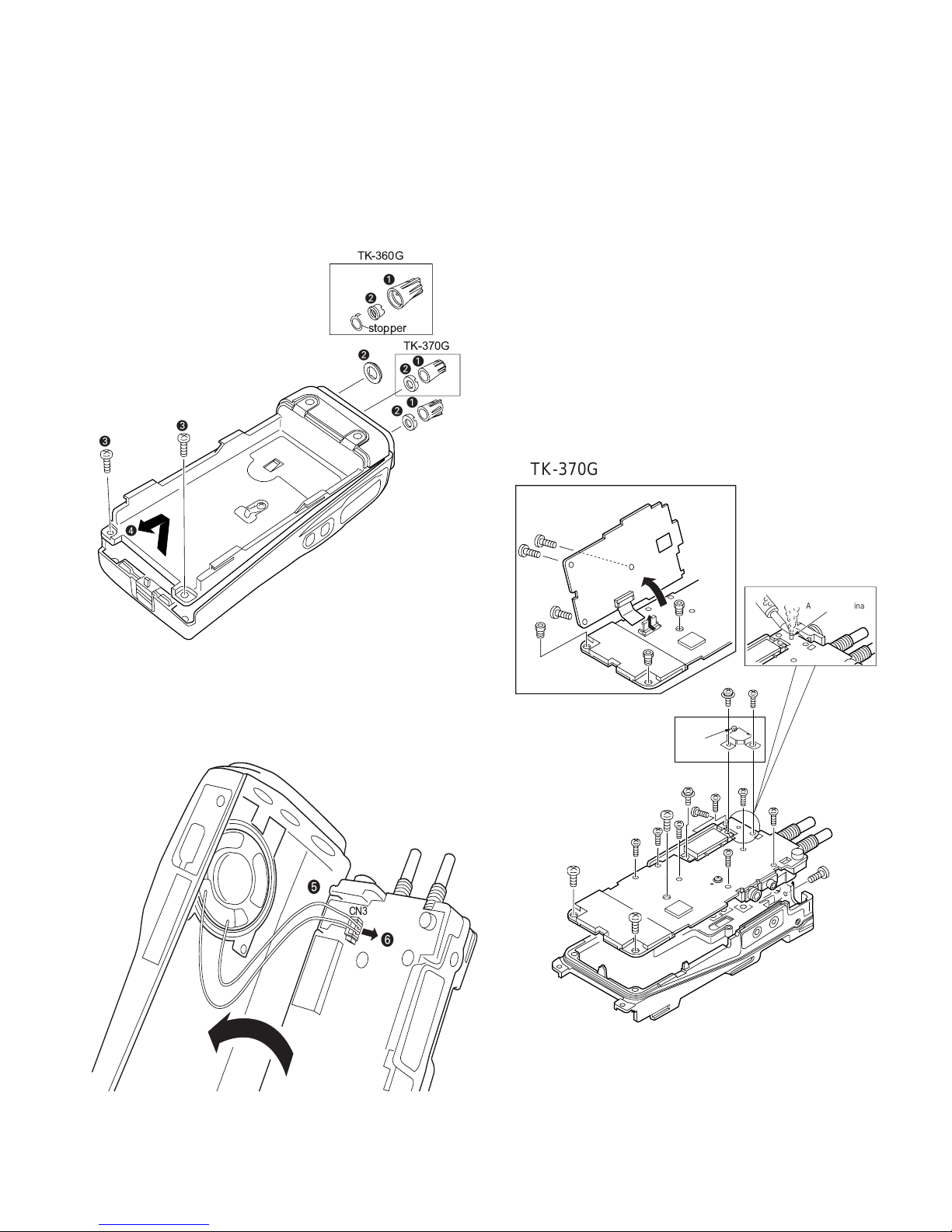
DISASSEMBLY FOR REPAIR
Separating the case assembly from the chassis.
1. Remove the two knobs z and three round units x.
2. Remove the two screws
3. Expand the right and left sides of the bottom of the case
assembly, lift the chassis, and remove it from the case
assembly
c
v
v
.
c
c
.
TK-360G
z
x
stopper
TK-370G
x
z
x
z
x
Separating the chassis from the unit.
• TK-360G
1. Remove the twelve small screws m, and remove the three
large screws
2. Remove the solder from the antenna terminal using a solder
iron then lift the unit off (X57).
,
.
• TK-370G
1. Remove the three screws ..
Lift the unit (X54), and rise up the connecter lever in the
arrow with your finger
Remove the three hexagonal bosses
twelve screws
2. Remove the solder from the antenna terminal using a
soldering iron, then lift the unit off (X57).
m
.
/
, and remove the
Ω
.
TK-370G
❾
❾
X54-
4. Taking cure not to cut the speaker lead b, open the chassis and
case assembly, and pull the speaker lead with connector
n
.
b
CN3
n
❾
TK-360G/370G
E, (N)E only
❽
➐
X57-
❽
❿
X57-
➐
➐
Unsolder
➐
➐
➐
❽
➐
➐
➐
➐
Antenna teminal
➐
➐
17
 Loading...