

Page 1

INSTRUCTION MANUAL
MODE D’EMPLOI
MANUAL DE INSTRUCCIONES
BEDIENUNGSANLEITUNG
MANUAL DI ISTRUZIONI
GEBRUIKSAANWIJZING
A321
B654
C987
D
0
TK-270G/ TK-370G
VHF FM TRANSCEIVER/
UHF FM TRANSCEIVER
EMETTEUR-RECEPTEUR FM VHF/
EMETTEUR-RECEPTEUR FM UHF
TRANSCEPTOR DE FM VHF/
TRANSCEPTOR DE FM UHF
VHF-FM-TRANSCEIVER/
UHF-FM-TRANSCEIVER
RICETRASMETTITORE FM VHF/
RICETRASMETTITORE FM UHF
VHF FM ZENDONTVANGER/
UHF FM ZENDONTVANGER
KENWOOD CORPORATION
© B62-1294-30 (E,NE,NT)
09 08 07 06 05 04 03
Page 2

TK-270G/ TK-370G
ENGLISH
VHF FM TRANSCEIVER/
UHF FM TRANSCEIVER
INSTRUCTION MANUAL
Page 3

THANK YOU
We are grateful you chose KENWOOD for your land
mobile radio applications. We believe this easy-to-use
transceiver will provide dependable communications to
keep personnel operating at peak efficiency.
KENWOOD transceivers incorporate the latest in
advanced technology. As a result, we feel strongly that
you will be pleased with the quality and features of this
product.
MODELS COVERED BY THIS MANUAL
• TK-270G: VHF FM Transceiver
• TK-370G: UHF FM Transceiver
NOTICES TO THE USER
◆
GOVERNMENT LAW PROHIBITS THE OPERATION OF
UNLICENSED RADIO TRANSMITTERS WITHIN THE
TERRITORIES UNDER GOVERNMENT CONTROL.
◆
ILLEGAL OPERATION IS PUNISHABLE BY FINE OR
IMPRISONMENT OR BOTH.
◆
REFER SERVICE TO QUALIFIED TECHNICIANS ONLY.
SAFETY: It is important that the operator is aware of
and understands hazards common to the operation of
any transceiver.
WARNING:
EXPLOSIVE ATMOSPHERES (GASES, DUST, FUMES, etc.)
Turn off your transceiver while taking on fuel, or while parked in
gasoline service stations.
i
Page 4

PRECAUTIONS
Observe the following precautions to prevent fire,
personal injury, and transceiver damage.
• Do not modify this transceiver for any reason.
• Do not expose the transceiver to long periods of
direct sunlight, nor place it close to heating
appliances.
• Do not place the transceiver in excessively dusty,
humid, and/or wet areas, nor on unstable surfaces.
• If an abnormal odor or smoke is detected coming
from the transceiver, switch OFF the power
immediately and remove the optional battery pack
from the transceiver. Contact your KENWOOD
dealer.
ii
Page 5

CONTENTS
UNPACKING AND CHECKING EQUIPMENT................... 1
Supplied Accessories ...................................... 1
PREPARATION .................................................. 3
Charging the Optional NiCd Battery Pack .................. 3
Installing/ Removing the Optional NiCd Battery Pack ..... 3
Installing the Antenna ..................................... 4
Installing the Belt Clip ..................................... 5
Installing the Cap over the Speaker/ Microphone
Jacks ........................................................ 5
Installing the Optional Speaker/ Microphone ........... 5
GETTING ACQUAINTED ........................................ 6
Display ...................................................... 8
PROGRAMMABLE AUXILIARY FUNCTIONS ................. 9
OPERATING BASICS...........................................10
Switching Power ON/OFF ................................ 10
Adjusting the Volume ..................................... 10
Selecting a Group or Channel ...........................10
Adjusting the Squelch Level ............................. 11
Placing a Call .............................................. 12
Receiving a Call ........................................... 12
CHANNEL SCAN ...............................................13
Priority Scan ...............................................14
Channel Lockout ..........................................14
Revert Channel ............................................14
DTMF CALLS ...................................................15
Manual Dialling ............................................15
iii
Page 6

Storing DTMF Numbers ....................................16
Confirming Stored DTMF Numbers .....................16
Dialling Stored DTMF Numbers ......................... 17
Clearing Stored DTMF Numbers .......................... 17
Redialling .................................................. 17
CODE SQUELCH ...............................................18
Receiving ..................................................18
Transmitting ...............................................19
SELECTIVE CALL ..............................................20
Receiving ..................................................21
Transmitting ...............................................22
2-TONE SIGNALLING .......................................... 23
Receiving ..................................................23
Transmitting ...............................................24
5-TONE SIGNALLING .......................................... 25
AUXILIARY FUNCTIONS ......................................26
Selecting an Output Power ............................... 26
Time-out Timer (TOT) ....................................26
Busy Channel Lockout (BCL) ............................. 27
Talk-Around ................................................27
Battery Voltage Level .....................................28
Lamp .......................................................28
Beginning/ End of Transmission Signal ................ 28
Monitor/Squelch .......................................... 29
iv
Page 7

UNPACKING AND CHECKING EQUIPMENT
metI rebmuntraP ytitnauQ
annetnA
)EN,E(G072-KT5X-5960-09T
1)TN(G072-KT5X-0860-09T
)EN,E(G073-KT5X-2860-09T
pilctleB3X-4260-92J1
teswercS5X-2102-99N1
skcajenohporcim/rekaepS
pac
3X-1530-90B1
enohporcim/rekaepS
tekcarbgnikcol
4X-3944-12J1
launamnoitcurtsnIXX-4921-26B1
Note:
The following unpacking instructions are for use by your
KENWOOD
factory.
Carefully unpack the transceiver. We recommend that
you identify the items listed in the following table before
discarding the packing material. If any items are
missing or have been damaged during shipment, file a
claim with the carrier immediately.
■ Supplied Accessories
dealer, an authorized
KENWOOD
service facility, or the
Note:
A market code (E, NE, or NT) can be found on the label
attached to the package box.
1
Page 8
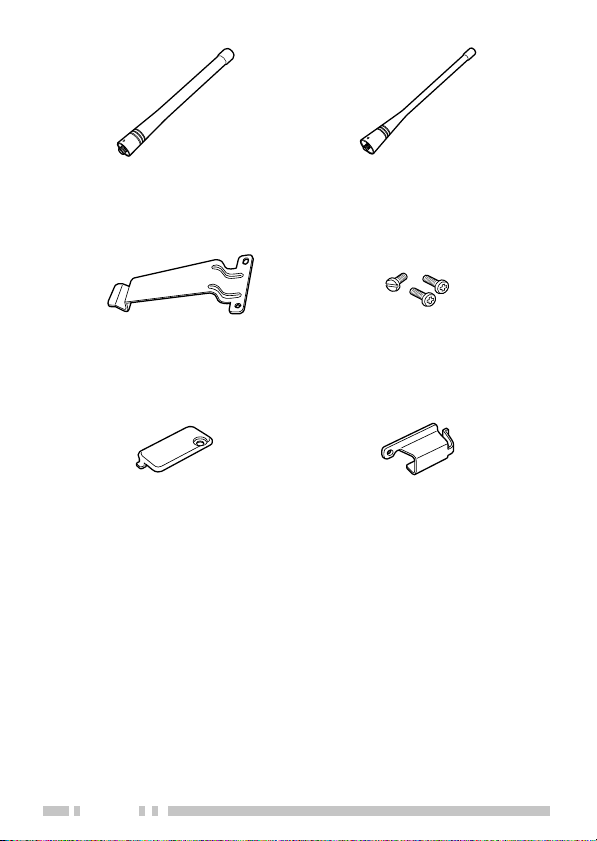
Antenna (TK-270G)
Antenna (TK-370G)
Belt clip
Speaker/ microphone
jacks cap
2
Screw set
Speaker/ microphone
locking bracket
Page 9
PREPARATION
■ Charging the Optional NiCd Battery Pack
The optional battery pack is not charged at the
factory; charge it before use (refer to the battery
pack instruction manual).
◆
DO NOT RECHARGE THE BATTERY PACK IF IT IS
ALREADY FULLY CHARGED. DOING SO MAY CAUSE THE
LIFE OF THE BATTERY PACK TO SHORTEN OR THE
BATTERY PACK MAY BE DAMAGED.
◆
AFTER RECHARGING THE BATTERY PACK, DISCONNECT
IT FROM THE CHARGER. IF THE CHARGER POWER IS
RESET (TURNED ON AFTER BEING TURNED OFF),
RECHARGING WILL START AGAIN AND THE BATTERY
PACK WILL BECOME OVERCHARGED.
Initially charging the battery pack after purchase or
extended storage (greater than 2 months) will not
bring the battery pack to its normal operating
capacity. After repeating the charge/discharge cycle
two or three times, the operating capacity will
increase to normal.
■ Installing/ Removing the Optional NiCd Battery Pack
Only use the KNB-14 and KNB-15A battery packs
with this transceiver.
◆
DO NOT SHORT THE BATTERY TERMINALS OR DISPOSE
OF THE BATTERY BY FIRE.
◆
NEVER ATTEMPT TO REMOVE THE CASING FROM THE
BATTERY PACK.
3
Page 10
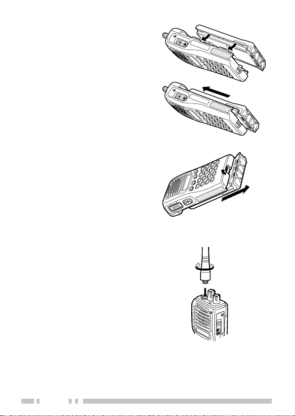
1 Match the four grooves
of the battery pack with
the corresponding
guides on the back of
the transceiver.
2 Slide the battery pack
along the back of the
transceiver until the
release latch on the
base of the transceiver
locks.
3 To remove the battery
pack, pull back on the
release latch and slide
the pack away from the
transceiver.
■ Installing the Antenna
Screw the antenna into the
connector on the top of the
transceiver by holding the
antenna at its base and
turning it clockwise until
secure.
4
Page 11
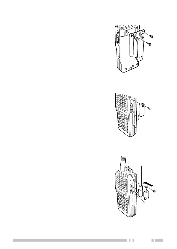
■ Installing the Belt Clip
If necessary, attach the belt
clip using the two supplied
3 x 8 mm screws.
Note:
If the belt clip is not installed,
its mounting location may get hot
during continuous transmission or
when left sitting in a hot
environment.
■ Installing the Cap over the Speaker/ Microphone Jacks
If you are not using an
optional speaker/
microphone, install the
cover over the SP/MIC
jacks using the supplied
3 x 6 mm screw.
■ Installing the Optional Speaker/ Microphone
1 Insert the speaker/
microphone plugs into
the SP/MIC jacks.
2 Install the speaker/
microphone locking
bracket over the plugs
using the supplied
3 x 6 mm screw.
5
Page 12

GETTING ACQUAINTED
Antenna
ww
w
qq
ww
q
qq
rr
r
rr
tt
t
tt
yy
y
yy
uu
u
uu
ii
i
ii
0
The transceiver is shown with the optional KNB-14 battery pack.
qq
q Rotary encoder
qq
ee
e
ee
A321
B654
C987
D
Speaker
Microphone
oo
o
oo
!0!0
!0
!0!0
Your dealer can program the encoder as either
Group Up/Down or Channel Up/Down (default
setting). Rotate to select a group or channel. Also
rotate to adjust the squelch in Squelch Adjustment
mode.
ww
w LED indicator
ww
Lights red while transmitting. Lights green while
receiving. Flashes orange while receiving a Code
Squelch or Selective Call code, or a 2-Tone, 5-Tone,
or DTMF signal that matches the one set up in your
transceiver. Flashes red when the battery power is
low while transmitting.
6
Page 13

ee
e Power switch/ Volume control
ee
Turn clockwise to switch ON the transceiver. Rotate
to adjust the volume. To switch OFF the transceiver,
turn counterclockwise fully.
rr
r PTT (Push-to-Talk) switch
rr
Press this switch, then speak into the microphone to
call a station.
tt
t Side 1 key
tt
This is a PF (Programmable Function) key. Press it
to activate its auxiliary function {page 9}.
yy
y Side 2 key
yy
This is a PF (Programmable Function) key. Press it
to activate its auxiliary function {page 9}.
uu
u O, ●,
uu
tt
t,
tt
ss
s keys
ss
These are PF (Programmable Function) keys. Press
each key to activate its auxiliary function {page 9}.
ii
i DTMF keypad
ii
Used for storing and transmitting DTMF numbers.
oo
o SP/MIC jacks
oo
Connect an optional speaker/ microphone here.
!0!0
!0 Display
!0!0
(See page 8.)
Note:
The PF keys are programmed with default functions:
•
Side 1 key:
•
Side 2 key:
• O
key:
• ●
key:
tt
•
t
key:
tt
ss
•
s
key:
ss
Lamp
Monitor A
Scan
Scan Del/Add
Talk Around
RF Power Lo
7
Page 14

nocI noitpircseD
.reviecsnartsihtnodesutoN
silennahcdetcelesehtnehwsraeppA
.ysub
,enoT-2,FMTD,TQD,TQnehwsraeppA
yb(detavitcaedsignidocedenoT-5ro
ehtgnisserp rotinoM .)yek
edoCaevieceruoynehwsraeppA
,enoT-2,llaCevitceleS,hcleuqS
oslA.llacgnillangiSFMTDro,enoT-5
edoCgnisutimsnartuoynehwsraeppa
.llaCevitceleSrohcleuqS
.gninnacselihwsraeppA
ehtnorewopwolgnisuelihwsraeppA
.lennahcdetceles
silennahcdetcelesehtnehwsraeppA
.ecneuqesgninnacsehtnidedulcni
eht,lennahcdetcelesehtsyalpsiD
nehw(stigidFMTD,levelhcleuqs
ro,stigidgnimrifnoc,stigidgniretne
deviecersegassemdna,)llacagnikam
.llaCevitceleSaiv
■ Display
8
Page 15

PROGRAMMABLE AUXILIARY FUNCTIONS
Side 1, Side 2, O, ●,
with the auxiliary functions listed below.
1llaCoNseY
2llaCoNseY
nwoDlennahCseYseY
pUlennahCseYseY
nwoDpuorGseYseY
pUpuorGseYseY
kcoLyeKseYseY
pmaLseYseY
rotinoMseYseY
enoNseYseY
laideRseYoN
oLrewoPFRseYseY
nacSseYseY
ddA/leDnacSseYseY
yrtnEllaCleSoNseY
ffOhcleuqSseYseY
dnuorA-klaTseYseY
edocnEenoT-2seYoN
tt
t, and
tt
noitcnuF
retcarahCyalpsiDseYseY
lennahCemoHseYseY
yratnemoMrotinoMseYseY
yratnemoMhcleuqSseYseY
ss
s can be programmed
ss
ledoM
enoT-2/FMTD
ledoMenoT-5
9
Page 16

OPERATING BASICS
■ Switching Power ON/OFF
Turn the Power switch/ Volume control clockwise to
switch the transceiver ON.
Turn the Power switch/ Volume control counter-
clockwise to switch the transceiver OFF.
If the Radio Password function is programmed,
“PASSWORD” will appear on the display when the
power is turned ON. To unlock the transceiver, enter
the password, then press the O key. If you enter the
wrong password, an error tone sounds and the
transceiver remains locked. The password can
contain a maximum of 6 digits.
■ Adjusting the Volume
Rotate the Power switch/ Volume control to adjust
the volume. Clockwise increases the volume and
counterclockwise decreases it.
•You may need to adjust the volume more precisely
while communicating with other parties.
Note:
If your dealer programmed
onto a PF key, you can press that key to hear background noise while
adjusting the volume level (refer to “Monitor/Squelch” on page 29).
■ Selecting a Group or Channel
Squelch Momentary
or
Squelch Off
Rotate the Rotary encoder (or press the keys
programmed as Group Up/Down or Channel Up/
Down) to choose your desired group or channel.
Clockwise increases the number and counterclockwise decreases it.
• If a group or channel has not been programmed, it
cannot be used.
10
Page 17

■ Adjusting the Squelch Level
Squelch is used to silence the speaker when no
signals are present. When squelch is turned OFF,
you will hear background noise from the speaker.
When it is ON, you will not hear background noise.
The squelch level you select determines when
squelch will turn OFF and ON. If you select a
squelch level that is too high, you will not hear
weaker signals. If you select a squelch level that is
too low, you will hear background noise between
signals.
To adjust the squelch:
1 Press and hold the Side 2 key, then press the
key.
• “SQL” and the current squelch level appear.
2 Rotate the Rotary encoder to select a squelch
level from 0 ~ 9.
• Clockwise increases the squelch level and
counterclockwise decreases it.
3 Press any key other than the key programmed as
Lamp to complete the setting.
• Normal operation is restored.
ss
s
ss
11
Page 18

■ Placing a Call
1 Make sure no parties are currently transmitting on
your selected channel.
2 Press the PTT switch and speak into the
microphone in your normal speaking voice.
• For best sound quality at the receiving station, hold
the microphone approximately 1.5 inches
(3 ~ 4 cm) from your mouth.
3 Release the PTT switch to receive.
■ Receiving a Call
Your dealer may have programmed QT or DQT
signalling on your transceiver. If your selected
channel is programmed with one of these features,
you will hear calls only when another party in your
system makes a call. All other calls will not be
heard.
If your selected channel is not set up with QT or
DQT, you will hear calls made by any party (not just
those in your system).
12
Page 19

CHANNEL SCAN
Scan is useful for monitoring signals on the channels
programmed on the transceiver. When scanning, the
transceiver checks for a signal on each channel, and
only stops on a channel if a signal is present.
The transceiver will remain on a busy channel until the
signal is no longer present. Your dealer programs the
delay time between signal drop-out and scan
resumption. If a signal is received during the delay
time, the transceiver will remain on the same channel.
Note:
◆
You can only use Scan if your dealer has programmed at least 2
channels on the transceiver. Also, there must be at least 2 channels
not locked out of Scan.
◆
Ask your dealer for an explanation on how Channel Scan functions
when using Code Squelch, Selective Call, or 2-Tone signalling.
To start scanning, press the key programmed as Scan.
• Scanning starts from the current channel and ascends
through the channel numbers.
• The SCN icon and “SCAN” appear on the display.
To end Scan, press the Scan key again.
13
Page 20

■ Priority Scan
If your dealer set up a priority channel on your
transceiver, the transceiver will continuously monitor
that channel while receiving a signal on another
channel. When a signal is received on the Priority
channel, the transceiver immediately switches to that
channel.
• “P” appears on the display.
The transceiver will remain on the Priority channel
until the signal drops out. Your dealer programs the
delay time between signal drop-out and scan
resumption.
■ Channel Lockout
If programmed by your dealer, you can select
channels to lock out of the scanning sequence.
Perform the following steps while not in Scan mode.
1 Rotate the Rotary encoder to select the channel
you want to lock out of Scan.
2 Press the key programmed as Scan Del/Add.
• Each press of Scan Del/Add toggles the lockout
status of the selected channel ON and OFF.
• Channels that are included in Scan are represented
by an “A” on the display. Channels locked out of
Scan do not have an “A” on the display.
■ Revert Channel
During Scan, pressing the PTT switch to transmit will
cause the transceiver to select the revert channel.
Your dealer programs the Revert channel for your
transceiver. Consult your dealer for details.
14
Page 21

DTMF CALLS
■ Manual Dialling
There are two ways to manually call a number:
1) Press and hold the PTT switch, then enter the
desired digits on the keypad.
•You can enter the digits 0 ~ 9, A ~ D, , and #.
(A ~ D may be disabled by your dealer.)
• If programmed by your dealer, you do not need to
continuously hold the PTT switch. The transceiver
will remain in the transmit state for 2 seconds after
releasing each key.
• While transmitting DTMF tones, the microphone is
muted. You can monitor tones as they are
transmitted by listening to the speaker audio.
2) First enter the desired digits on the keypad (16
digits maximum).
• Each digit appears on the display as it is entered
and its corresponding DTMF tone sounds.
•You can enter the digits 0 ~ 9, A ~ D,
(A ~ D may be disabled by your dealer, however
you can still enter them if desired.)
• If you entered a wrong digit or decide not to dial the
number, press the O, ●,
After entering the desired digits, press the PTT
switch to make the call.
• The digits scroll across the display and their
corresponding DTMF tone sounds.
• If programmed by your dealer, no DTMF tone will
sound when “D” is transmitted. “D” is used for a
pause time. The pause duration is programmed by
your dealer.
tt
t, or
tt
ss
s key to exit.
ss
, and #.
15
Page 22

■ Storing DTMF Numbers
Note:
Auto Dialling must first be activated by your dealer.
You can store DTMF numbers (16 digits maximum)
in each of the 9 Auto Dial memory locations (1 ~ 9).
1 Press the # key.
• “D” appears on the display.
2 Enter the desired digits on the keypad.
•You can enter the digits 0 ~ 9, A ~ D, , and #.
(A ~ D may be disabled by your dealer, however
you can still enter them if desired.) When entering
“#”, you must first press the PTT switch.
tt
•To cancel, press O, ●,
t, or
tt
ss
s.
ss
3 Press the # key, then enter a single digit number
(1 ~ 9) for the memory location.
• The original display is restored.
■ Confirming Stored DTMF Numbers
To confirm the numbers stored in memory locations:
1 Press the key.
• “A” appears on the display.
2 Enter the desired memory location number (1 ~ 9).
• The stored digits are displayed.
• If programmed by your dealer, no DTMF tone will
sound when “D” is transmitted. “D” is used for a
pause time. The pause duration is programmed by
your dealer.
3 Press any key other than the PTT switch to exit.
16
Page 23

■ Dialling Stored DTMF Numbers
To call a number stored in a memory location:
1 Press the key.
• “A” appears on the display.
2 Enter the desired memory location number (1 ~ 9).
• The stored digits are displayed.
3 Press the PTT switch.
• If programmed by your dealer, no DTMF tone will
sound when “D” is transmitted. “D” is used for a
pause time. The pause duration is programmed by
your dealer.
■ Clearing Stored DTMF Numbers
To clear the numbers from a memory location:
1 Press the # key twice.
• “D- CLR” appears on the display.
•To cancel the process, press any key other than
1 ~ 9.
2 Enter the desired memory location number (1 ~ 9).
■ Redialling
You can redial the last number you transmitted (16
digits maximum).
1 Press the key, then press the 0 key.
• “A” and the digits are displayed.
2 Press the PTT switch.
Note:
Switching OFF the transceiver power clears the redial
memory.
17
Page 24

CODE SQUELCH
Code Squelch is enabled or disabled by your dealer.
This function turns the transceiver squelch OFF only
when it receives the DTMF code that has been set up in
your transceiver. Transceivers that do not transmit the
correct code will not be heard. Consequently, you can
communicate with a specific party without listening to
other parties using the same channel.
Your dealer may also activate Group Call for your
transceiver. This is useful when you want to send
information to a number of units in a fleet. Ask your
dealer for details.
Note:
Code Squelch cannot be used on channels programmed with
Selective Call or 2-Tone Signalling.
■ Receiving
When you receive a signal containing the correct
code, squelch turns OFF and you will hear the call.
• “CALL” appears on the display and the LED indicator
flashes orange.
•To mute the speaker after squelch turns OFF, press the
key programmed as Monitor or Squelch.
•Your dealer can program squelch to automatically turn
back ON after a specific time period elapses.
• If Transpond for Code Squelch is programmed, an
acknowledgment signal is returned to the calling
station. Transpond does not function when you are
called with a Group code. Transpond for Code
Squelch can send an alert tone, a transceiver ID code,
or a code stored in memory location 1.
• If Tone Alert for Code Squelch is programmed, an alert
tone will sound when the correct code is received.
18
Page 25

■ Transmitting
1 Press and hold the PTT switch.
2 Enter the code of the transceiver you want to call
or enter a Group code on the keypad.
• If desired, you can send codes the same way you
make DTMF calls {page 15}. Both manual methods
can be used or you can store codes in memory,
then dial them from a memory location.
• “CALL” appears on the display and the LED
indicator lights red.
3 Use the transceiver the same as in a regular call;
press the PTT switch to transmit and release it to
receive.
• The called transceiver’s squelch will turn OFF while
you are transmitting. After you stop transmitting,
the squelch will turn back ON after a pre-set time
period elapses. This time period is programmed by
your dealer.
• When you release the PTT switch, squelch turns
OFF and the LED indicator flashes orange. When
you receive a signal, the LED indicator lights green.
When the signal drops out, the LED indicator
flashes orange again. If no signal is received for a
pre-determined time, squelch turns back ON.
• Pressing the key programmed as Monitor or
Squelch at any time will turn the squelch back ON.
19
Page 26

SELECTIVE CALL
Selective Call is enabled or disabled by your dealer.
This function is similar to Code Squelch {page 18}. The
differences from Code Squelch are:
•You can send or receive message codes containing a
maximum of 5 digits.
• Selective Call turns the squelch OFF only when the
transceiver receives a predetermined DTMF code in the
correct sequence:
1) A 3-digit ID code
2) A 1-digit Intermediate code
3) A message code (up to 5 digits)
Your dealer may also activate Group Call for your
transceiver. This is useful when you want to pass
information to a number of units in a fleet. Ask your
dealer for details.
Note:
Selective Call cannot be used on channels programmed with
Code Squelch or 2-Tone Signalling.
20
Page 27

■ Receiving
When you receive the correct ID and Intermediate
codes, squelch turns OFF and you will hear the call.
If a message code is also received, the message
appears on the display
• “CALL” appears on the display and the LED indicator
flashes orange.
• When you receive a call with your ID code, “C”
appears on the display (i.e.- C 12345).
• When you receive a call with your Group code, “A”
appears on the display (i.e.- A 12345).
• When no message is received, “NO DATA” appears on
the display.
•You can clear a message by pressing any key other
than the key programmed as Lamp.
•To mute the speaker after squelch turns OFF, press
the key programmed as Monitor or Squelch.
•Your dealer can program squelch to automatically turn
back ON after a specific time period elapses.
• If Transpond for Selective Call is programmed, an
acknowledgment signal is returned to the calling
station. Transpond does not function when you are
called with a Group code. Transpond for Selective
Call can send an alert tone, a transceiver ID code, or a
code stored in memory location 1.
• If Tone Alert for Selective Call is programmed, an alert
tone will sound when the correct code is received.
21
Page 28

■ Transmitting
1 Press and hold the PTT switch.
2 Enter the code of the transceiver you want to call
or enter a Group code on the keypad.
• Be sure to enter the ID or Group code, followed by
the Intermediate code of the transceiver you want
to call. If desired, you can also enter a message
code of up to 5 digits.
• If desired, you can send codes the same way you
make DTMF calls {page 15}. Both manual
methods can be used or you can store codes in
memory, then dial them from a memory location.
• “CALL” appears on the display and the LED
indicator lights red.
3 Use the transceiver the same as in a regular call;
press the PTT switch to transmit and release it to
receive.
• When you release the PTT switch, squelch turns
OFF and the LED indicator flashes orange. When
you receive a signal, the LED indicator lights green.
When the signal drops out, the LED indicator
flashes orange again. If no signal is received for a
pre-determined time, squelch turns back ON.
• Pressing the key programmed as Monitor or
Squelch at any time will turn the squelch back ON.
22
Page 29

2-TONE SIGNALLING
2-Tone Signalling is enabled or disabled by your dealer.
This function turns the transceiver optional signalling
OFF only when it receives the 2-tone signal that has
been set up in your transceiver. Transceivers that do
not transmit the correct tones will not be heard.
Your dealer may also activate Group Call for your
transceiver. Ask your dealer for details.
■ Receiving
When you receive a signal containing the correct
tones, optional signalling turns OFF and you will hear
the call.
• “CALL” appears on the display and the LED indicator
flashes orange.
• If your dealer has programmed the transceiver to turn
the squelch OFF, you can mute the speaker by
pressing the key programmed as Monitor or Squelch.
•Your dealer can program optional signalling and
squelch to automatically turn back ON after a specific
time period elapses.
• If Transpond for 2-Tone Signalling is programmed, an
acknowledgment signal is returned to the calling
station. Transpond for 2-Tone Signalling can transmit
an alert tone only.
• If Tone Alert for 2-Tone Signalling is programmed, an
alert tone will sound when the correct tones are
received.
23
Page 30

■ Transmitting
1 Press the key programmed as 2-Tone Encode.
•A 2-Tone code appears on the display.
2 Rotate the Rotary encoder to select your desired
2-Tone code.
3 Press the PTT switch and 2-Tone Encode key to
begin transmitting. Release the 2-Tone Encode
key when transmission has started. Release the
PTT switch to receive.
• When you release the PTT switch, optional
signalling turns OFF and the LED indicator flashes
orange. When you receive a signal, the LED
indicator alternates between green and orange.
When the signal drops out, the LED indicator
flashes orange again. If no signal is received for a
pre-determined time, optional signalling turns back
ON.
• Pressing the key programmed as Monitor or
Squelch at any time will turn the optional signalling
back ON.
24
Page 31

5-TONE SIGNALLING
5-Tone Signalling is either activated or deactivated by
your dealer.
5-Tone Signalling only opens the squelch when the
transceiver receives five tones corresponding to those
set up in your transceiver. When the squelch opens,
you will be able to hear the caller without any further
action.
After a correct 5-Tone signal is received and the squelch
opens, pressing the key programmed as Monitor will
cancel the connection.
If your dealer programmed Transpond for 5-Tone
Signalling, your transceiver will automatically send an
acknowledgment signal to stations that called you with
the correct signal.
Note:
This transceiver is also capable of decoding 2-Tone signals.
However, you cannot make 2-Tone calls unless 2-Tone Signalling has
been activated by your dealer.
25
Page 32

AUXILIARY FUNCTIONS
■ Selecting an Output Power
Each channel is programmed with either high or low
output power by your dealer. You can change the
output power of only channels programmed as high.
When you can reliably communicate with other
parties without using high power, select low power by
pressing the key programmed as RF Power Lo.
Each time you press RF Power Lo, the output power
toggles between high and low.
• Using low power conserves battery power and reduces
the risk of interfering with other communications.
• The “LO” icon appears when you are using low power.
Note:
◆
Pressing
low power causes an error tone to sound.
◆
When changing a channel from high power to low power, all
channels programmed with high power are changed to low.
■ Time-out Timer (TOT)
The purpose of the Time-out Timer is to prevent any
caller from using a channel for an extended period of
time.
If you continuously transmit for a period of time that
exceeds the programmed time, the transceiver will
stop transmitting and an alert tone will sound. To
stop the tone, release the PTT switch.
Your dealer can program a warning function to alert
you before the TOT expires. Continuously
transmitting for the time specified by your dealer will
cause the warning tone to sound.
26
RF Power Lo
while using a channel programmed with
Page 33

■ Busy Channel Lockout (BCL)
The Busy Channel Lockout feature is activated or
deactivated by your dealer.
When activated, BCL prevents you from interfering
with other parties who may be using the same
channel that you selected. Pressing the PTT switch
while the channel is in use will cause your
transceiver to emit an alert tone and transmission will
be inhibited (you cannot transmit). Release the PTT
switch to stop the tone and return to receive mode.
■ Talk-Around
You may occasionally experience an interruption in
service (due to a power failure, etc.). During such an
occurence, you can continue communication by
using the Talk-Around feature, if it has been
programmed by your dealer. Talk-Around allows you
to communicate directly with other transceivers,
without the use of a repeater. However, if the station
you want to contact is too far away, or there are
geographical obstacles in the way, you may not be
able to contact the station.
Toggle Talk-Around ON and OFF by pressing the key
programmed as Talk-Around.
• “T” or “TA” appears on the display while Talk-Around is
active.
• When using Talk-Around, the “receive” frequency is
used for both transmission and reception, and the QT/
DQT “decode” signalling is used for both encoding and
decoding.
27
Page 34

■ Battery Voltage Level
While transmitting, the transceiver automatically
checks the battery voltage level. When the voltage
level becomes low, the LED indicator flashes red.
When a tone sounds, transmission stops. Recharge
or replace the battery pack at this time.
■ Lamp
Press the key programmed as Lamp to toggle the
display backlight ON or OFF. The backlight
automatically turns OFF approximately 5 seconds
after it is switched ON.
Press any key other than Lamp while the backlight is
ON to reset the 5 second timer. The timer will reset
and the backlight will remain on for 5 seconds.
■ Beginning/ End of Transmission Signal
Your dealer can enable or disable the Beginning/
End of Transmission identification signals. These
signals are used to access and release some
repeaters and telephone systems.
To send a Beginning of Transmission signal, either
press the PTT switch, or press the key two times.
To send an End of Transmission signal, either
release the PTT switch or press the key followed
by the # key.
• Ask your dealer which method has been activated on
your transceiver.
28
Page 35

■ Monitor/Squelch
Your dealer can program a key with the Monitor or
Squelch function one of four ways:
Squelch Momentary: Press and hold the Squelch key to
hear background noise. Release the key to return to
normal operation.
Squelch Off: Momentarily press the Squelch key to hear
background noise. Press the key again to return to
normal operation.
Monitor Momentary: Press and hold the Monitor key to
deactivate QT, DQT, DTMF, 2-Tone, or 5-Tone
signalling. Release the key to return to normal
operation.
Monitor: Momentarily press the Monitor key to
deactivate QT, DQT, DTMF, 2-Tone, or 5-Tone
signalling. Press the key again to return to normal
operation.
You can use the Squelch key to listen to weak
signals that you cannot hear during normal operation
and to adjust the volume when no signals are
present on your selected channel.
29
 Loading...