

VHF FM TRANSCEIVER / VHF
TK-2317
调频手持对讲机
SERVICE MANUAL /
C version / C版本
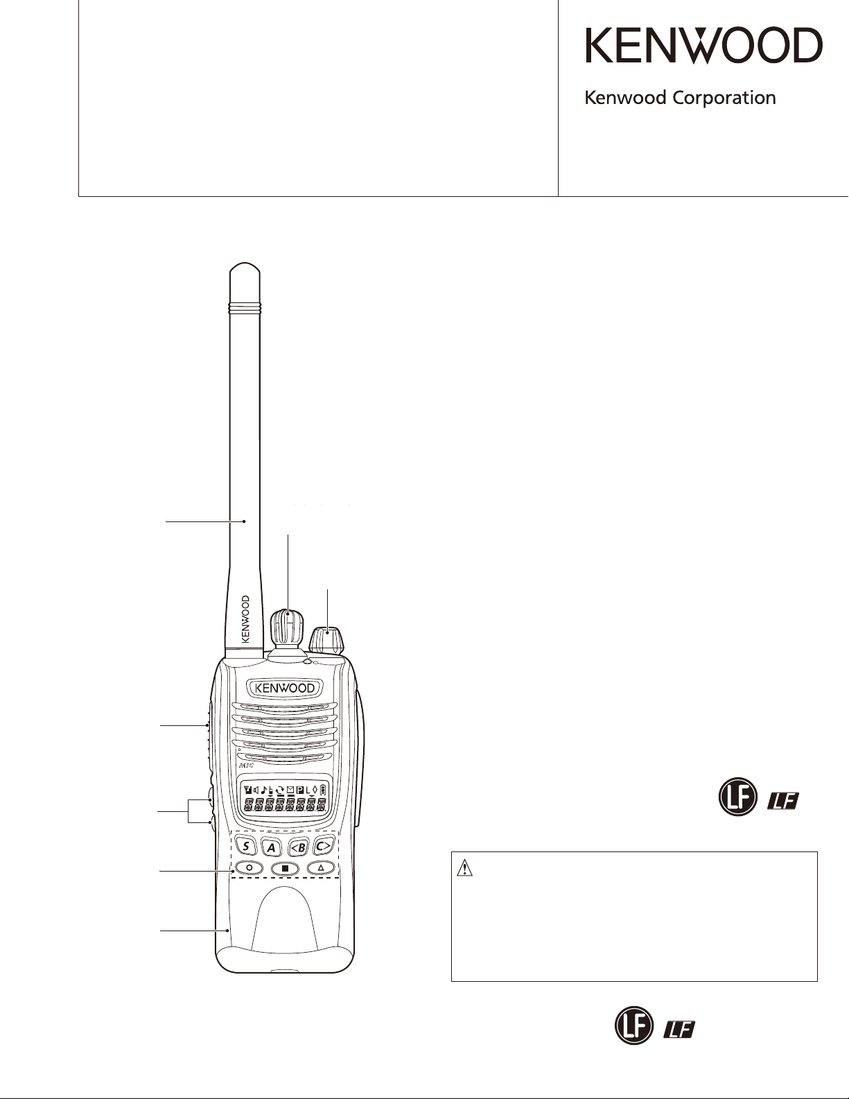
Knob (Selector)
Knob (Selector)
Helical antenna
天线
Helical antenna
(KRA-26: Option / )
可选件
旋钮(选择器)
(K29-9427-03)
Knob (Volume)
Knob (Volume)
旋钮(音量)
(K29-9309-13)
维修手册
© 2011-2 PRINTED IN JA PAN
B51-8957-00 (Y)
Button knob (PTT)
Button knob (PTT)
按钮 (PTT)
(K29-9425-03)
Button knob
(SIDE1/SIDE2)
钮扣按钮
Button knob
(侧面1/侧面2)
(SIDE1/SIDE2)
(K29-9426-03)
Key top (7key)
顶端按键 (7 键 )
Key top (7key)
(K29-9463-12)
Plastic cabinet assy
机壳
Plastic cabinet assy
(A02-4095-23)
This product complies with the RoHS directive for the European market.
无铅焊接通信产品
保护环境建伍领先
注意∶
在维修时请使用无铅焊锡
和相应的焊接工具
详细事项请访问如下网址了解 :
本产品是无铅化焊接产品
http://www.kenwoodhk.com.hk/
This product uses Lead Free solder.

TK-2317
CONTENTS /
GENERAL ....................................................3
SYSTEM SET-UP .........................................4
REALIGNMENT ...........................................5
DISASSEMBLY FOR REPAIR ...................15
CIRCUIT DESCRIPTION ...........................21
SEMICONDUCTOR DATA .........................29
COMPONENTS DESCRIPTION ................31
PARTS LIST ...............................................33
EXPLODED VIEW ......................................40
PACKING ...................................................41
ADJUSTMENT ...........................................42
PC BOARD
TX-RX UNIT (X57-7880-20) ....................52
SCHEMATIC DIAGRAM ............................56
目录
概 述..................................3
系统体系...............................4
模式组合...............................5
维修拆卸............................. 15
电路说明..............................21
半导体数据............................29
元件说明..............................31
零 件 表..............................33
部件分解图............................40
包 装.................................41
调 整.................................42
印刷电路板
收发单元 (X57-7880-20)..............52
原 理 图..............................56
BLOCK DIAGRAM .....................................62
LEVEL DIAGRAM ......................................64
OPTIONAL ACCESSORIES
KNB-29N (Ni-MH Battery Pack) ............65
KNB-45L (Li-ion Battery Pack) .............65
KNB-53N (Ni-MH Battery Pack) ............65
KMC-48GPS (GPS Speaker Microphone)
SPECIFICATIONS ..................BACK COVER
..65
方 块 图..............................62
电 平 图..............................64
可选附件
KNB-29N ( 镍氢电池 ).................65
KNB-45L ( 锂离子电池 )...............65
KNB-53N ( 镍氢电池 ).................65
KMC-48GPS (GPS 扬声器麦克风 ) .......65
规 格...............................封底
2

TK-2317
Document Copyrights
Copyright 2011 by Kenwood Corporation. All rights re-
served.
No part of this manual may be reproduced, translated,
distributed, or transmitted in any form or by any means, electronic, mechanical, photocopying, recording, or otherwise,
for any purpose without the prior written permission of Kenwood.
Disclaimer
While every precaution has been taken in the preparation of this manual, Kenwood assumes no responsibility
for errors or omissions. Neither is any liability assumed for
damages resulting from the use of the information contained
herein. Kenwood reser ves the right to make changes to any
products herein at any time for improvement purposes.
文档版权信息
Kenwood Corporation 拥有版权 2011。保留所有权利。
未经 Kenwood 公司预先书面同意,无论出于何种目的,均
不得以任何形式或任何方式包括电子、机械、影印、录音或
其他方式复制、翻译、分发或传播本手册的任何部分。
免责声明
Kenwood 公司在准备本文档时已采取所有必要的预防措施,
恕不对错误或疏漏承担任何责任,也不对因使用本文中所含
的信息而导致的损害负责。Kenwood 公司保留出于改进的需要
而随时对文中的产品信息做出更改的权利。
GENERAL /
INTRODUCTION
SCOPE OF THIS MANUAL
This manual is intended for use by experienced tech ni cians familiar with similar types of commercial grade com mu ni ca tions equipment. It contains all required service
in for ma tion for the equipment and is current as of the publication date. Changes which may occur after publication
are covered by either Service Bulletins or Manual Revisions.
These are is sued as required.
ORDERING REPLACEMENT PARTS
When ordering replacement parts or equipment in for ma tion, the full part identifi cation number should be in clud ed.
This applies to all parts : components, kits, or chassis. If the
part number is not known, include the chassis or kit number
of which it is a part, and a suffi cient description of the re quired component for proper identifi cation.
概述
引言
本手册的范围
本手册是提供给熟悉通信专业并且具有维修经验的技术人
员使用的。它包括了维修该设备所需要的全部资料和现行出
版日期。在出版后可能发生变动,如果需要,可以参照《维
修通报》或《手册修订本》进行补充。
替换零件的订购
当订购替换零件或设备资料时,应注意完整的零件识别号
码。所有的零件均有识别号码∶元件,组件或机壳。如果不
知道零件的号码,为了正确地识别,必须注明此元件所属的
机壳或组件的号码,并对元件进行充分的说明。
3
TK-2317
PERSONAL SAFETY
The following precautions are recommended for personal
safety:
• DO NOT transmit until all RF connectors are verifi ed se cure and any open connectors are properly terminated.
• SHUT OFF and DO NOT operate this equipment near
elec tri cal blasting caps or in an explosive atmosphere.
• This equipment should be serviced by a qualifi ed tech ni cian only.
SERVICE
This transceiver is designed for easy servicing. Refer
to the sche mat ic diagrams, printed circuit board views, and
align ment procedures contained within.
Model Type TX-RX unit
TK-2317 C X57-7880-20 136~174MHz
Frequency
range
Remarks
IF1: 49.95MHz
LOC: 50.4MHz
个人安全
个人安全为了个人的安全,请注意下列事项∶
•
在没有认真核实所有射频插头之前或有任何一个脱开的插
头没有连接到相应端口上的情况下均不要发射。
• 在电爆管附近或在易燃性气体环境中,必须关闭电源,不
要操作本设备。
• 本设备只应该由有资格的技术人员进行维修。
维修服务
为了便于维修本设备,建立了完整的维修服务体系,提供
了包括原理图,印刷电路板图和调整步骤在内的资料供参考。
型 号 类型 收发单元 频率范围 备 注
TK-2317 C X57-7880-20 136 ~ 174MHz
IF1: 49.95MHz
LOC: 50.4MHz
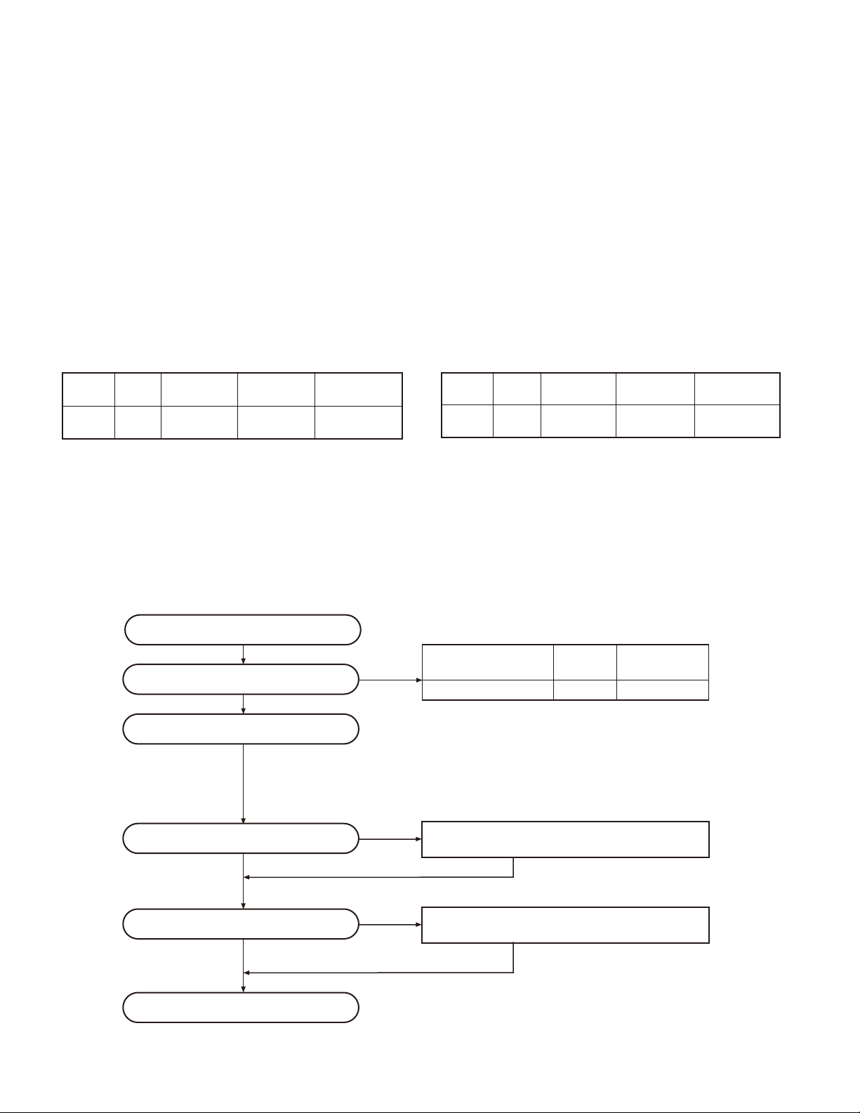
SYSTEM SET-UP /
Merchandise received
接收订单
Choose the type of transceiver
选择手持对讲机的类型
Transceiver programming
手持对讲机编程
Are you using the optional antenna?
您使用可选件天线吗 ?
否
NO /
Are you using the speaker microphone?
您使用扬声器麦克风吗 ?
否
NO /
系统体系
Frequency range (MHz) RF power Type
频率范围 (MHz)
TX/RX 136~174 5.0W TK-2317C
A personal computer, programming interface (KPG-22/22A),
and FPU (programming software) are required for programming.
(The frequency, TX power HI/LOW, and signaling data are
programmed for the transceiver.)
编程时需要个人计算机,编程接口 (KPG-22/22A) 和 FPU( 编程软件 )。
( 为手持对讲机设定频率,常规系统特性,TX 高 / 低功率,以及信令数据。)
YES /
YES /
是
是
KMC-21, KMC-45 or KMC-48GPS Speaker microphone
KRA-22 or KRA-26 Optional antenna
KRA-22 或 KRA-26 可选件天线
KMC-21,KMC-45 或 KMC-48GPS 扬声器麦克风
射频功率
类型
(Option)
( 可选件 )
Delivery
交货
4
TK-2317
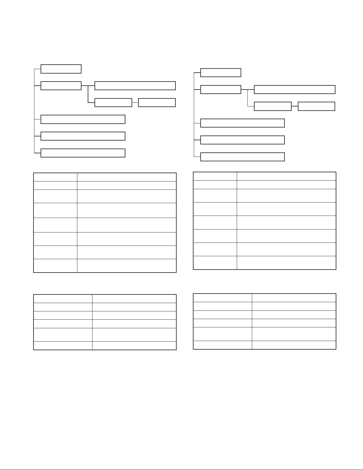
1. Modes
User mode
PC mode
PC test mode
Wireless clone mode
Firmware version information mode
Self-programming mode
Mode Function
User mode For normal use.
PC mode
Data programming
mode
PC test mode
Wireless clone
mode
Firmware version
information mode
Self-programming
mode
Used for communication between the transceiver and PC.
Used to read and write frequency data and
other features to and from the transceiver.
Used to check the transceiver using the PC.
This feature is included in the FPU.
Used to transfer programming data from one
transceiver to another.
Used to confi rm the internal fi rmware version.
You can program the frequency signaling and
other function using only the transceiver.
REALIGNMENT /
Data programming mode
PC tuning mode
模式组合
1. 模式
User mode
用户模式
数据编程模式
PC mode
PC 模式
Wireless clone mode
无线复制模式
Firmware version information mode
模 式 功 能
用户模式 一般使用。
PC 模式 用于手持对讲机与计算机之间的通信。
数据编程模式 用于阅读和写入频率数据以及其他功能。
PC 测试模式
无线复制模式
固件版本信息 用于确认内部固件版本。
自台编程模式
固件版本信息
自台编程模式
Self-programming mode
用于使用计算机检测手持对讲机。
此特性包括在 FPU 内。
用于从一个手持对讲机编程数据复制到另
一个手持对讲机。
您可以只使用手持对讲机自身来进行编程
频率、信令和其他功能。
Data programming mode
PC 测试模式
PC test mode
PC 调谐模式
PC tuning mode
2. How to Enter Each Mode
Mode Operation
User mode Power ON
PC mode Received commands from PC
Wireless clone mode [<B] + Power ON (Two seconds)
Firmware version
information mode
Self-programming mode [S] + Power ON (Two seconds)
[Side1] + [Side2] + Power ON (Two
seconds)
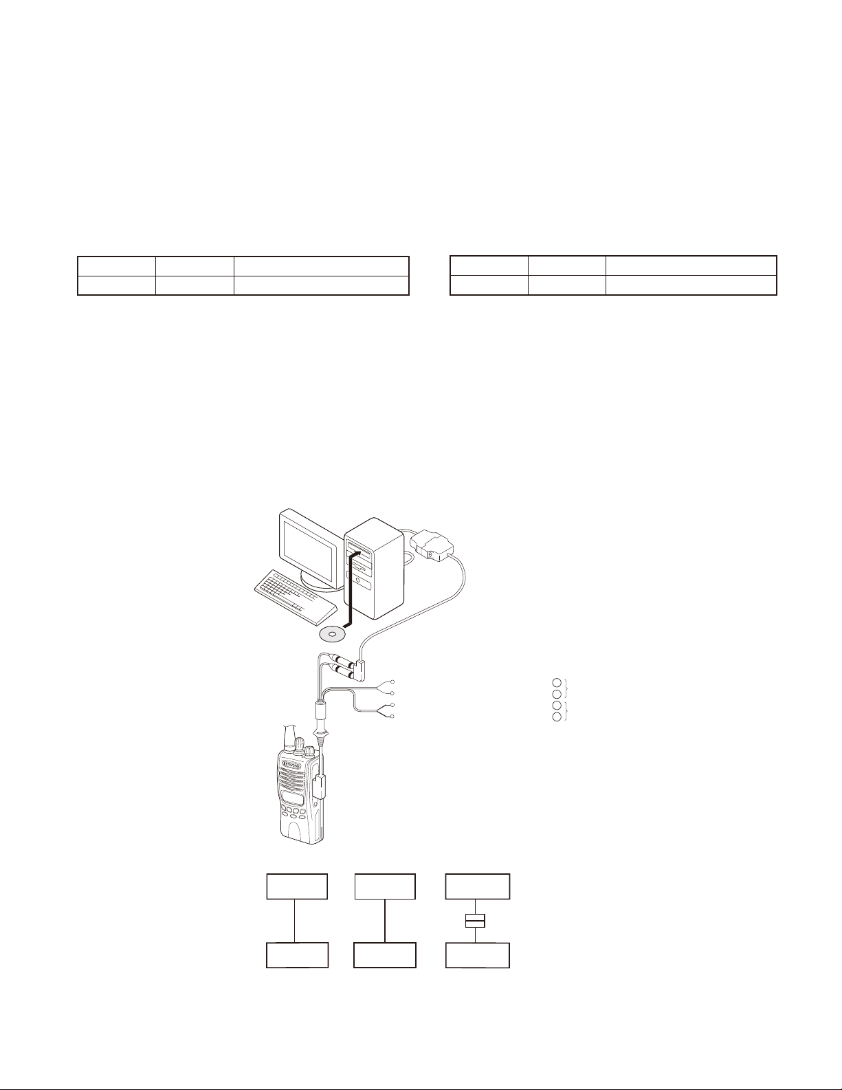
3. PC Mode
3-1. Preface
The transceiver is programmed by using a personal computer, a programming interface (KPG-22/22A, USB adapter
(KCT-53U)) and FPU (programming software).
The programming software can be used with a PC. Figure 1 shows the setup of a PC for programming.
2. 如何进入每一种模式
模 式 功 能
用户模式 接通电源
PC 模式 从计算机接收指令
无线复制模式 [<B]+ 接通电源(2 秒钟)
固件版本信息 [ 侧面 1]+[ 侧面 2]+ 接通电源(2 秒钟)
自台编程模式 [S]+ 接通电源(2 秒钟)
3.PC 模式
3-1. 前言
手持对讲机采用个人电脑、编程接口 (KPG-22/22A,U S B
适配器 (KCT-53U)) 和 FPU( 编程软件 ) 进行编程。
编程软件可以在 PC 上进行使用。图 1 给出了 P C 进行编程
的设置。
5

TK-2317
REALIGNMENT /
3-2. Connection Procedure
1. Connect the transceiver to the personal computer with
the interface cable and USB adapter (when the interface
cable is KPG-22A, the KCT-53U can be used).
Note:
• You must install the KCT-53U driver in the computer to
use the USB adapter (KCT-53U).
• When using the USB adapter (KCT-53U) for the fi rst time,
plug the KCT-53U into a USB port on the computer with
the computer power ON.
2. When the POWER is switched on, user mode can be entered immediately. When the PC sends a command, the
transceiver enters PC mode.
When data is read from the transceiver, the red LED
lights.
When data is written to by the transceiver, the green LED
lights.
Note:
• The data stored in the personal computer must match
Model Name and Model Type when it is written into EEPROM.
• Do not press the [PTT] key during data transmission or
reception.
模式组合
3-2. 连接操作
1. 使用接口电缆和 USB 适配器将手持对讲机连接到个人电脑
( 接口电缆为 KPG-22A 时,可以使用 KCT-53U)。
注意 :
•
必须在电脑上安装 KCT-53U 驱动程序才能使用 USB 适配器
(KCT-53U)。
•
首次使用 USB 适配器 (KCT-53U) 时,请在电脑开机的情况
下将 KCT-53U 插入电脑的 USB 端口。
2. 手持对讲机电源打开时,可以立即进入用户模式 PC 发送
指令时,手持对讲机进入 PC 模式。
手持对讲机发送数据时,红色的 LED 点亮。
手持对讲机接收数据时,绿色的 LED 点亮。
注意 :
• 个人电脑保存的数据写入 EEPROM 时,必须与机型和类型相
符。
• 请勿在数据发送或接收期间按 [PTT] 键。
3-3. KPG-22/KPG-22A Description
(PC programming interface cable: Option)
The KPG-22/22A is required to interface the transceiver
with the computer. It has a circuit in its D-sub connector
(KPG-22: 25-pin, KPG-22A: 9-pin) case that converts the
RS-232C logic level to the TTL level.
The KPG-22/22A connects the SP/MIC connector of the
transceiver to the RS-232C serial port of the computer.
3-4. KCT-53U Description (USB adapter: Option)
The KCT-53U is a cable which connects the KPG-22A to
a USB port on a computer.
When using the KCT-53U, install the supplied CD-ROM
(with driver software) in the computer. The KCT-53U driver
runs under Windows 2000, XP or Vista (32-bit).
3-5. FPU (Programming Software) Description
The FPU is the programming software for the transceiver
supplied on a CD-ROM. This software runs under windows
XP, Vista or 7 on a PC. The software on this disk allows a
user to program the transceiver transceivers via Programming interface cable (KPG-22/22A).
Note:
• Use the FPU that matches the market when you fi rst set
the market code and model name/frequency data to the
service unit. The unit set by mistake cannot be restored.
3-3.KPG-22/KPG-22A 说明
(PC 编程接口电缆 :选购件 )
将手持对讲机与电脑相连需要 KPG-22/22A。该电缆的
D-sub 连接器 (KPG-22:25 针,KPG-22A :9 针 ) 盒具有将
RS-232C 逻辑电平转换为 TTL 电平的电路。
KP G-22/22A 将手持对讲机的 SP/MIC 连接器连接到电脑的
RS-232C 串行端口。
3-4. KCT-53U 说明 (USB 适配器 :选购件 )
KCT-53U 是将 KPG-22A 连接到电脑 USB 端口的电缆。
使用 K C T -53U 时,请在电脑上安装附带的 CD-ROM( 带有
驱动程序软件 )。K C T-53U 驱动程序在 Windows2000,XP 或
Vista(32 位 ) 下运行。
3-5.FPU( 编程软件 ) 说明
FPU 是 CD-ROM 附带的用于手持对讲机的编程软件。该软件
在 PC 的 WindowsXP、Vista 或 7 下运行。该光盘上的软件允
许用户通过编程接口电缆 (KPG-22/22A) 对手持对讲机进行编
程。
注意 :
• 初次设置服务单元的市场代码和机型 / 频率数据时,请使
用与市场相符的 FPU。若单元设置有误,将无法予以恢复。
6
TK-2317
REALIGNMENT /
3-6. Programming with PC
If data is transferred to the transceiver from a PC with the
FPU, the data for each set can be modifi ed.
Data can be programmed into the EEPROM in RS-232C
format via the SP/MIC jack.
In this mode the PTT line operate as TXD and RXD data
lines respectively.
List of FPU for transceiver
Model Type FPU
TK-2317 C KPG-134D (C)
模式组合
3-6. 使用 PC 编程
如果使用 FPU 将数据从 P C 传输到手持对讲机,则每套手
持对讲机的数据均可修改。
通过 SP/MIC 插孔可以将数据以 RS-232C 格式写入 EEPROM。
在该模式下,PTT 线路分别用作 TXD 和 RXD 数据线路。
手持对讲机的 FPU 名单
型 号 类 型 FPU
TK-2317 C KPG-134D(C)
KPG-22 or KPG-22A or KPG-22A+KCT-53U
KPG-22 或 KPG-22A 或 KPG-22A+KCT-53U
Illustration is KPG-22.
PC
插图为 KPG-22
FPU
Gray
Gray/Black
1.5D-XV Lead wire
1.5D-XV Shield wire
Tuning cable /
(E30-3216-05)
PC
D-SUB
(25-pin / )
25 针
KPG-22
Transceiver Transceiver Transceiver
手持对讲机 手持对讲机 手持对讲机
调谐电缆
PC
D-SUB
(9-pin / )
9针
KPG-22A
灰色
灰色/黑色
1.5D-XV 导线
1.5D-XV 屏蔽线
PC
USB
KCT-53U
KPG-22A
+
SP
–
+
MIC
–
Fig. 1 / 图1
7

TK-2317
REALIGNMENT /
4. Wireless Clone Mode
4-1. Outline
“Wireless Clone Mode” copies the transceiver data to an-
other transceiver.
The dealer can copy the transceiver data to another
transceiver even without the use of a personal computer.
4-2. Example
The transceiver can copy the programming data to one or
more transceivers via RF communication.
The clone source and clone target/s must be in wireless
clone mode.
4-3. Operation
1. To switch the clone target/s to Wireless Clone mode,
press and hold the [<B] key while turning the transceiver
power ON.
2. Wait for 2 seconds. “CLONE” appears on the LCD, followed by “FRQTBL 1”.
3. Select a channel table number using the [Selector] knob.
4. To switch the clone source to Wireless Clone mode,
press and hold the [<B] key while turning the transceiver
power ON.
5. Wait for 2 seconds. “CLONE” appears on the LCD, followed by “FRQTBL 1”.
6. Select the same channel table number as the clone target/s.
7. Press the [S] key on the clone master to begin data transmission. When the clone target starts to receive data, the
green LED will light and “CLONING” will appear on the
LCD. The source unit will display “MASTER”.
8. When the clone source fi nishes sending data, a “confi rmation” tone will sound and “COMPLETE” will appear on
the LCD. If data transmission failed while cloning, the target unit will produced an error tone and “CLONE NG” will
appear on the LCD.
9. If the cloning fails, no data will be available in the target
unit when it is returned to User mode.
10. When the cloning is successful, the target unit's “Scan”
and “Key lock” functions will return to their default values
(Scan = OFF, Key lock = OFF).
11. The source will remain in clone mode after cloning. The
target unit will return to user mode after a successful
cloning.
Note:
• The dealer can clone data to two or more transceivers by
repeating the above procedures.
• If the transceivers wireless clone Mode is confi gured as
“Disabled”, the transceiver cannot enter Clone mode.
• The table shown below will cover the frequency tables
used for wireless cloning.
• Wireless clone mode cannot be entered in battery low
state.
• A unit cannot be a “Source Unit” if it is unprogrammed. If
the [S] key is pressed, an “error” tone will sound.
• Once a unit is set to be the source, it cannot be a target
after the data has been transmitted. This protects the
data in the source unit.
• MSK signaling is used in cloning.
模式组合
4. 无线复制模式
4-1. 概要
“无线复制模式”可以将一台手持对讲机的数据复制到其
它的手持对讲机。
经销商甚至不使用个人电脑也可以将一台手持对讲机的数
据复制到其它的手持对讲机。
4-2. 例
手持对讲机可以通过 RF 通信复制编程数据到一台或更多
的手持对讲机。
复制主机和复制子机必须处于无线复制模式。
4-3. 操作方法
1. 将子机切换到无线复制模式,接通 (ON) 手持对讲机电源
开关的同时,持续按 [<B] 键。
2. 等待 2 秒。LCD 上显示“CLONE”,然后显示“FRQTBL 1”。
3. 用 [ 选择器 ] 旋钮选择频率表号码。
4. 将主机切换到无线复制模式,打开手持对讲机电源 (ON)
的同时,持续按 [<B] 键。
5. 等待 2 秒。在 LCD 上显示“CLONE”,然后显示“FRQTBL 1”。
6. 选择与复制子机相同的频率表号码。
7. 按复制主机上的 [S] 键,开始传输数据。当复制子机开接
收数据时,绿色 LED 将亮灯,并且“CLONING”显示在 LCD 上。
主机将显示出“MASTER”。
8. 当复制主机完成数据传送,将发出一个“确认”音,并且
在 LCD 上显示出“COMPLETE”。如果复制中数据通讯失败,
子机将发出错误音,而且在 LCD 上显示出“CLONE NG”。
9. 如果复制失败,子机回到用户模式时会无可用数据。
10. 当复制成功时,子机的“扫描”和“键锁定”功能将返回
到它们的初始值 ( 扫描= OFF,键锁定= OFF)。
11. 主机在复制后将停留在复制模式。复制成功后,子机将返
回到用户模式。
注∶
• 经销上可以把同样的数据反复地复制到两台或更多的手持
对讲机。
• 如果手持对讲机的无复制模式被设定为“禁用”,则手持
对讲机不能进入复制模式。
• 此表是使用于无线复制的频率表。
• 在电池低电压状态时,不能进入无复制模式。
• 如果没有被编程,就不能成为“主机”。如果 [ S] 键被按,
将会发出“错误”音。
• 手持对讲机一旦被设定为主机,而且数据被传送之后,它
就不能成为子机。此功能是为了保护主机内的数据。
• MSK 信号用于复制。
• 电子干扰有可能导致无线复制时数据传送失败,如在工作
台上受到电波或电磁的干扰。
8
TK-2317
REALIGNMENT /
• Electronic interface may cause a failure in data transfer
during Wireless Clone, such as when waveforms or electromagnetics are being performed at the workbench.
• Wireless clone mode can be used ONLY by the authorized service personnel.
• The wireless clone mode setting must be confi gured as
“Disable” before being delivered to the end-user.
• To wireless clone, replace the antenna from both the
source transceiver and the target transceiver with a dummy load.
• The transmit output power is automatically set to Low in
Clone mode.
4-4. Adding the Data Password
If the Data password is set to the transceiver, you must
enter the password to activate a clone mode. The maximum
length of the password is 6 digits.
The following describes how to enter the password.
1. Press and hold the [<B] key for 2 seconds while turning
the transceiver power on.
2. “CLN.LOCK.R”(When the Read authorization password
is set to the transceiver.) / “CLN.LOCK.W” (When the
Overwrite password is set to the transceiver.) is displayed
on the LCD.
3. If the [selector] knob is rotated while “CLN.LOCK.R”/
“CLN.LOCK.W” is displayed, the number (0 to 9) fl ashes
on the LCD.
When you press the [C>] key, the currently selected num-
ber is determined.
If you press the [A] key, the least digit of the password is
deleted.
If you press the [S] key after entering the password in this
procedure, “FRQTBL 1” is displayed if the entered password is correct.
If the password is incorrect, “CLN.LOCK.R”/ “CLN.LOCK.
W” is redisplayed. (with error tone)
模式组合
• 无复制模式只可以由授权的服务人员使用。
•
在向最终用户交货之前,无复制模式必须设置为“禁用”。
•
无复制时,取下主手持对讲机和子手持对讲机的天线并装
上假负载。
• 在复制模式,手持对讲机输出功率自动地被设定为低功率。
4-4. 增加数据密码
如果数据密码被设定于手持对讲机,则您必须先输入密码
才能启动复制模式。密码的最大长度为 6 位数字。
输入密码的方法说明如下。
1. 打开手持对讲机电源的同时,持续按 [<B]键2秒。
2.“CLN.LOCK.R”( 当读取授权密码被设定到手持对讲机时 )
/“CL N.LOCK. W”( 重写密码被设定到手持对讲机时 ) 被
显示在 LCD。
3. 在“CLN.LOCK.R”/“CLN.LOCK.W”被显示时,如果 [ 选
择器 ] 旋钮被转动,在 LCD 上会闪烁出数字 (0 ~ 9)。
当您按了 [C>] 键,通常被选择的数字将被确定。
如果您按了 [A] 键,密码的最小位数字将被删除。
在此程序中输入了密码,并且被输入的密码正确,如果您
按了 [S] 键,则显示出“FRQTBL 1”。
如果密码错误,则继续显示“CLN.LOCK.R”/“CLN.LOCK.W”。
( 发出错误音 )
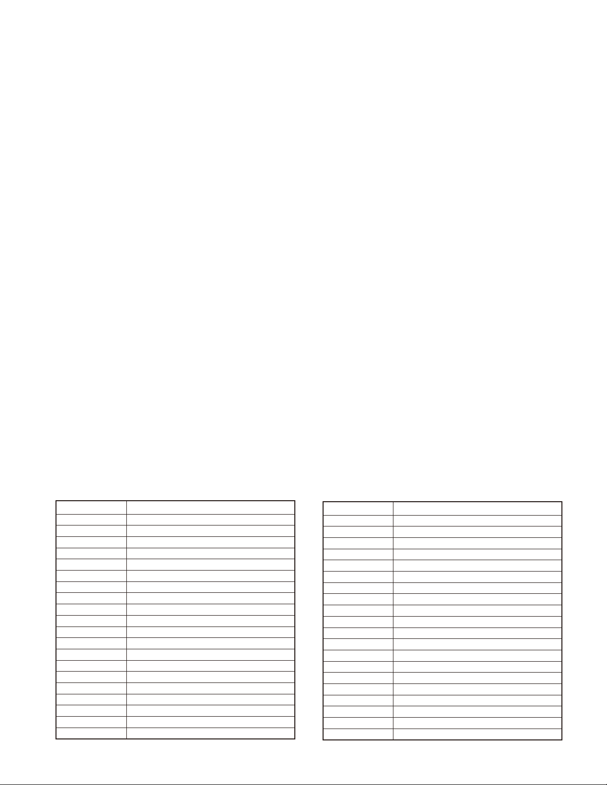
• Clone frequency table
No. Operating frequency 136~174 (MHz)
1 136.000
2 138.000
3 140.000
4 142.000
5 144.000
6 146.000
7 148.000
8 150.000
9 152.000
10 154.000
11 156.000
12 158.000
13 160.000
14 162.000
15 164.000
16 166.000
17 168.000
18 170.000
19 172.000
20 174.000
• 复制频率表
号码 操作频率 136 ~ 174 (MHz)
1 136.000
2 138.000
3 140.000
4 142.000
5 144.000
6 146.000
7 148.000
8 150.000
9 152.000
10 154.000
11 156.000
12 158.000
13 160.000
14 162.000
15 164.000
16 166.000
17 168.000
18 170.000
19 172.000
20 174.000
9

TK-2317
REALIGNMENT /
5. Firmware Version Information Mode
Tur n the transceiver ON with the [Side1] and [Side2] keys
held down. Then, the version is displayed during holding the
[Side1] and [Side2] keys.
6. Self Programming Mode
Write mode for frequency data and signaling, etc. To be
used ONLY by the authorized service person maintaining the
user's equipment. After programming, reset the FPU to the
“Self- Programming” disabled mode. Transceivers CANNOT
be delivered to the end-user in the self-programming mode.
6-1. Enter to the Self Programming Mode
Press and hold the [S] key for 2 seconds while turning
the transceiver power on.
When the transceiver enters in the self programming
mode, “1- 1” is displayed 2 seconds after “SELF” is displayed.
Note:
This mode (self programming mode) cannot be set when
it has been disabled with the FPU.
模式组合
5. 固件版本信息
按下[侧面1]和[侧面2]键打开手持对讲机的电源。然
后按[侧面1]和[侧面2]键显示版本。
6. 自台编程模式
频率数据和信令等的写入模式。只可以由负责维护用户设
备的授权服务人员使用。编程之后,复位自台编程模式为禁
用状态。手持对讲机不能以自台编程模式开启的状态交付给
最终用户。
6-1. 进入自台编程模式
打开手持对讲机电源的同时,持续按 [S]键2秒。
当手持对讲机进入了自台编程模式,显示“SELF”2 秒钟,
然后显示“1-1”。
注∶
当自台编程模式被 FPU 禁用时,此模式不能被设定。
6-2. Adding the Data Password
If the Data password is set to the transceiver, you must
enter the password to activate a self programming mode.
The maximum length of the password is 6 digits.
The following describes how to enter the password.
1. Press and hold the [S] key for 2 seconds while turning
the transceiver power on.
2. “SLF.LOCK.R” (When the Read authorization password is
set to the transceiver.) / “SLF.LOCK.W” (When the Over-
write password is set to the transceiver.) is displayed on
the LCD.
3. If the [selector] knob is rotated while “SLF.LOCK.R”/ “SLF.
LOCK.W” is displayed, the number (0 to 9) fl ashes on the
LCD.
When you press the [C>] key, the currently selected num-
ber is determined.
If you press the [A] key, the least digit of the password is
deleted.
If you press the [S] key after entering the password in this
procedure, “SELF” is displayed if the entered password is
correct.
If the password is incorrect, “SLF.LOCK.R”/ “SLF.LOCK.W”
is redisplayed.
6-3. Channel Selection Mode
In this mode, the Zone or Channel can be selected.
Press and hold the [S] key for 2 seconds while turning
the transceiver power on to enter self programming mode.
When the transceiver enters in the self programming mode,
the transceiver automatically enters the Channel Selection
mode.
2 seconds after displaying “SELF", “1- 1” appears on the
LCD.
6-2. 增加数据密码
如果数据密码被设定到手持对讲机,则您必须输入密码来
激活自台编程模式。密码的最大长度为 6 位数字。
输入密码的方法说明如下。
1. 打开手持对讲机电源的同时,持续按 [S]键2秒。
2. “SLF.LOCK.R”( 当读取授权密码被设定到手持对讲机时 )
/“SL F.LOCK. W”( 重写密码被设定到手持对讲机时 ) 被
显示在 LCD。
3. 在“SLF.LOCK.R”/“SLF.LOCK.W”被显示时,如果 [ 选择器 ]
旋钮被转动,在 LCD 上会闪烁出数字 (0 ~ 9)。
当您按了 [C>] 键,通常被选择的数字将被确定。
如果您按了 [A] 键,密码的最小位数字将被删除。
在此程序中输入了密码,并且被输入的密码正确,如果您
按了 [S] 键,则显示出“SELF”。
如果密码错误,则继续显示“SLF.LOCK.R”/“SLF.LOCK.W”。
6-3. 信道选择模式
在此模式,可以选择区域或信道。
打开手持对讲机电源的同时,持续按 [S]键2秒,则进入
自台编程模式。当手持对讲机进入自台编程模式,则手持对
讲机将自动进入信道选择模式。
显示“SELF”2 秒钟之后,在 LCD 上出现“1-1”。
10
TK-2317
REALIGNMENT /
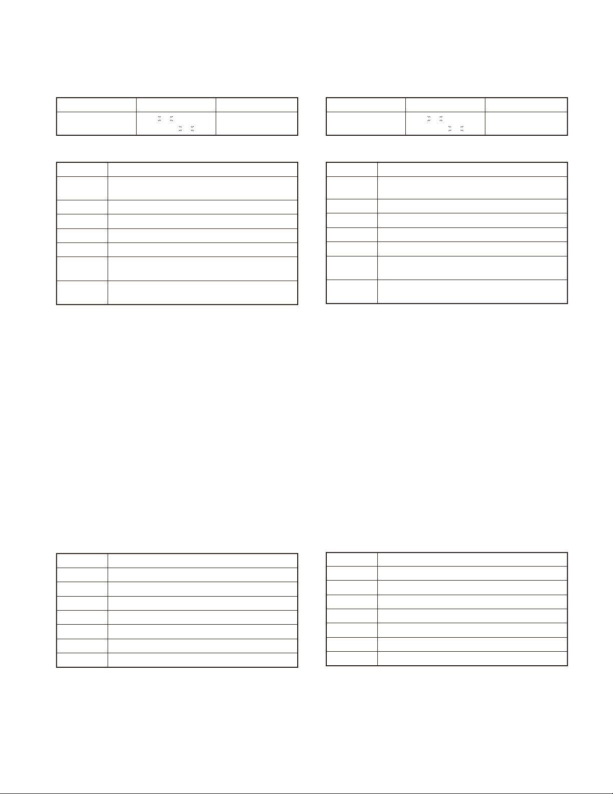
The setup item for channel selection mode is as follows.
Setup item Display Remarks
Select
Zone/Channel
Key operation
Key Key Function
[Selector]
[Side1] No action
[Side2] No action
[S] Enter the Item Setting mode
[A] Return to the Channel Selection mode
[<B]
[C>]
Toggle between Zone selection and Channel selection
Decrement the blinking Zone/Channel number by 1.
Press and hold to decrement in steps of 10.
Increment the blinking Zone/Channel number by 1.
Press and hold to decrement in steps of 10.
Note:
If a non-existing Zone-Channel is selected and the memory for all 128 channels is already fi lled, an error tone will
sound and “MEM.FULL” will appear on the LCD for 2 seconds.
***
***
-
-
***
***
Zone: 1~128
Channel: 1~128
模式组合
信道选择模式的设定项目如下所示。
设定项目 显示 备注
***
***
-
-
***
***
区域 : 1 ~ 128
信道 : 1 ~ 128
选择
区域/信道
键操作方法
键 键功能
[ 选择器 ] 在区域选择和信道选择之间切换
[侧面1] 无作用
[侧面2] 无作用
[S] 进入项目设定模式
[A] 返回到信道选择模式
[<B]
[C>]
以步进值 1 减小闪动的区域 / 信道。
按住时则以步进值 10 减小。
以步进值 1 增大闪动的区域 / 信道。
按住时则以步进值 10 增大。
注∶
如果选择了不存在的区域 - 频道和所有的 128 个信道的存
储器已经被占满,则将发出错误音,同时在 LCD 上显示“MEM.
FULL”2 秒钟。
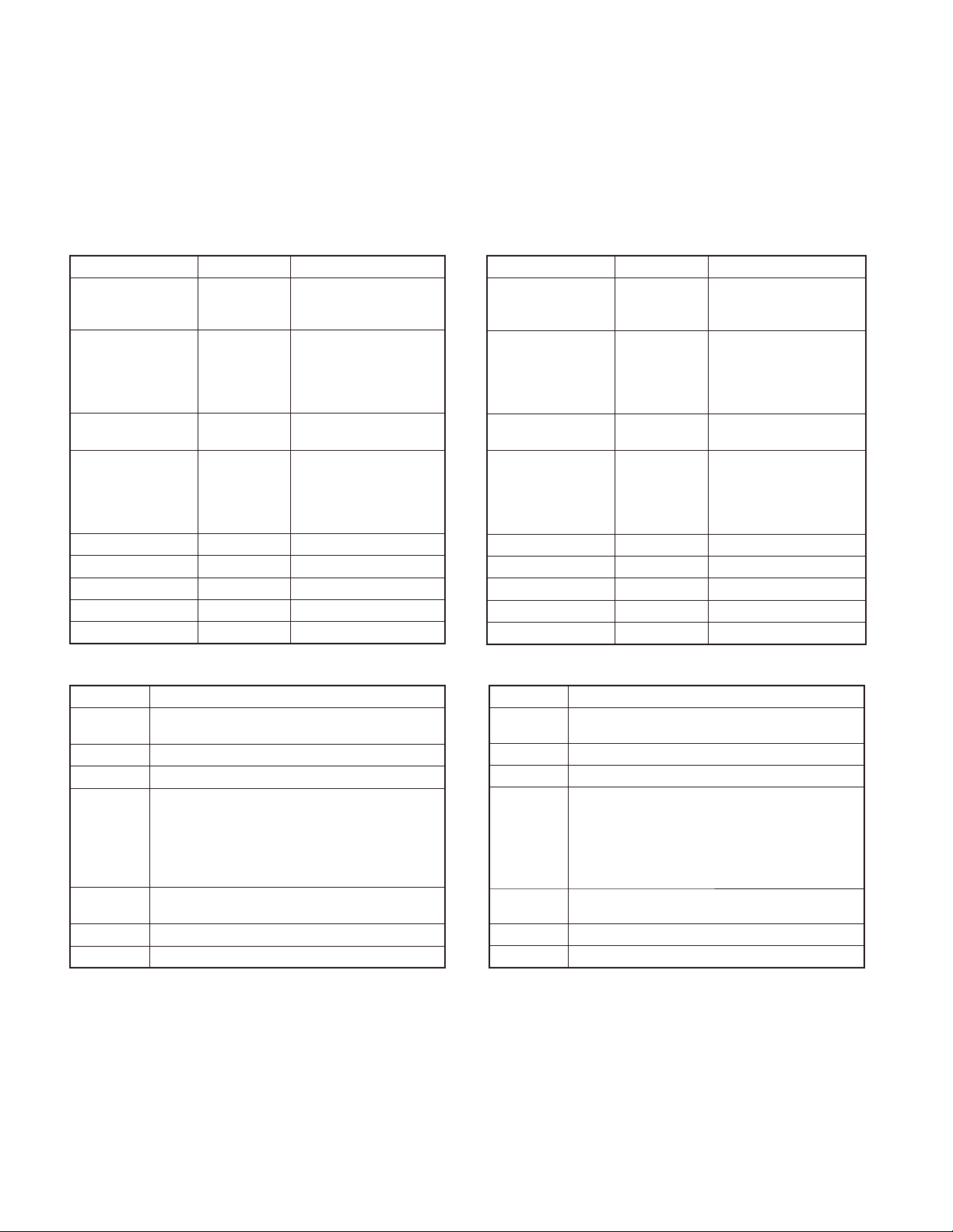
6-4. Item Selection Mode
In this mode, the following items can be selected.
• RX frequency
• RX signaling
• TX frequency
• TX signaling
• RF power Hi/Low
• Scan Del/Add
• Beat shift on/off
• Compander on/off
• Band W/N
When the [S] key is pressed in the Channel Selection
mode, the transceiver enters the Item Selection mode.
Key operation
Key Key Function
[Selector] The selected item changes
[Side1] No action
[Side2] No action
[S] Enter the Item Setting mode
[A] Return to the Channel Selection mode
[<B] Error tone sounds
[C>] Error tone sounds
6-4. 项目选择模式
在此模式,可以选择如下项目。
• RX 频率
•
RX 信令
•
TX 频率
• TX 信令
• RF 功率高/低
• 扫描删除/添加
• 拍频偏移 ON/OFF
• 压扩器 ON/OFF
• 宽带/窄带
在信道选择模式,当按了 [S] 键,手持对讲机将进入项目
选择模式。
键操作方法
键 键功能
[ 选择器 ] 变更选择项目
[侧面1] 无作用
[侧面2] 无作用
[S] 进入项目设定模式
[A] 返回到信道选择模式
[<B] 错误音
[C>] 错误音
11
TK-2317
REALIGNMENT /
6-5. Item Setting Mode
In this mode, the selected item in the Item Selection
mode can be programmed.
When the [S] key is pressed in the Item Selection mode,
the transceiver enters the Item Setting mode.
The setup items for item setting mode are as follows.
Setup item Display Remarks
1. RX FREQ
1. RX frequency
2. RX signaling
3. TX frequency
4. TX signaling
5. RF power Hi/Low 5. PWR
6. Scan Del/Add 6. SCN
7. Beat shift on/off 7. SFT
8. Compander on/off 8. CMP
9. Band W/N 9. BAND *** W/N
***.*****
2. RX SIG
TONE OFF/
QT
***.*
DQT
***
DQT
***
3. TX FREQ
***.*****
4. TX SIG
TONE OFF/
QT
***.*
DQT
***
DQT
***
***
***
***
***
Receive frequency
136.00000~174.00000MHz
/
Receive QT/DQT
N/
I
Transmit frequency
136.00000~174.00000MHz
/
Transmit QT/DQT
N/
I
HI/LOW
DEL/ADD
ON/OFF
ON/OFF
模式组合
6-5. 项目设定模式
在此模式,项目选择模式中被选择的项目可以进行编程。
在项目选择模式,当按了 [S] 键,手持对讲机将进入项目
设定模式。
项目设定模式的设定项目如下所示。
设定项目 显示 备注
1.RX 频率
2.RX 信令
3.TX 频率
4.TX 信令
5.RF 功率高/低 5.PWR*** HI/LOW
6. 扫描删除/添加 6.SCN*** DEL/ADD
7. 拍频偏移 ON/OFF 7.SFT*** ON/OFF
8. 压扩器 ON/OFF 8.CMP*** ON/OFF
9. 宽带 / 窄带 8.BAND*** W/N
1.RX FREQ →
***.*****
2.RX SIG →
TONE OFF/
QT***.*/
DQT***N/
DQT***I
3.TX FREQ →
***.*****
4.TX SIG →
TONE OFF/
QT***.*/
DQT***N/
DQT***I
接收频率
136.00000~174.00000MHz
接收 QT/DQT
发射频率
136.00000~174.00000MHz
发射 QT/DQT
Key operation
Key Key Function
[Selector]
[Side1] No action
[Side2] No action
[S]
[A]
[<B] Toggle/Decrease the blinking value.
[C>] Toggle/Increase the blinking value.
Changing the selection item (RX/TX frequency and
RX/TX signaling only)
• tore the current settings and return to the Item
Selection mode.
• A MHz digit of the frequency blinks. (RX/TX frequency only)
• The icon of the current signaling confi guration
blinks. (RX/TX signaling only)
Abort the current settings and return to the Item
Selection mode without backup
键操作方法
键 键功能
[ 选择器 ] 变更选择项目 ( 仅 RX/TX 频率和 RX/TX 信令 )
[侧面1] 无作用
[侧面2] 无作用
• 保存当前的设定和返回到项目选择模式。
[S]
[A] 放弃当前的设定并返回到项目选择模式。
[<B] 切换/减小闪动的数值
[C>] 切换/增大闪动的数值
• 频率的 MHz 数字闪动。( 仅 RX/TX 频率 )
• 当前的信令配置闪动。( 仅 RX/TX 信令 )
12
TK-2317
REALIGNMENT /
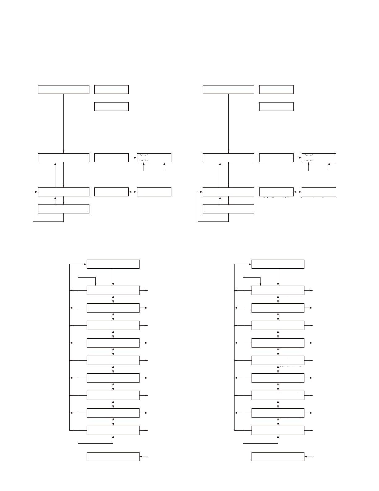
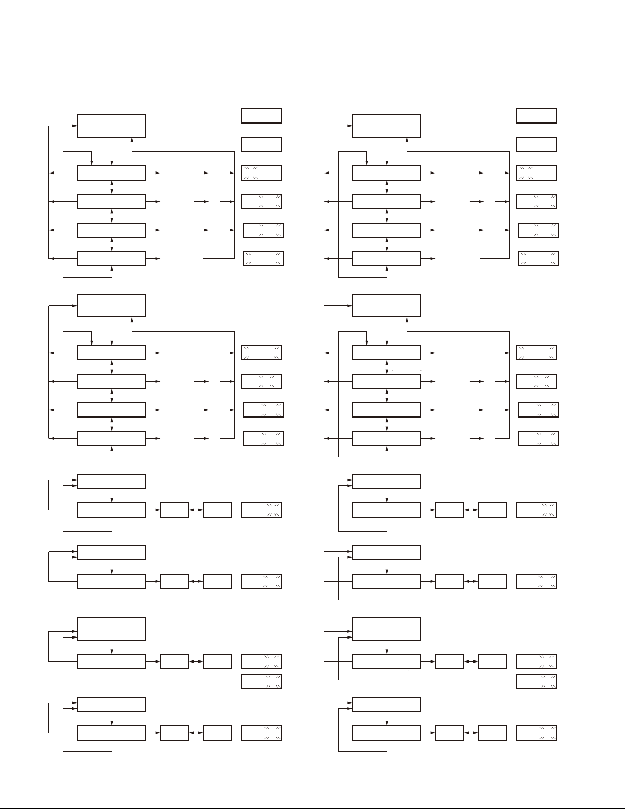
6-6. Self Programming Mode fl ow chart
Channel selection mode fl ow chart
■
[S]+Power ON
Data password
Read authorization password /
Overwrite password entry (6 digits)
[S]
Self programming mode
[S][A]
Channel selection mode
[S][A]
Item setting mode
[S]
Display
SLF.LOCK.R
or
SLF.LOCK.W
SELF
Zone selection
[<B] : Zone/Channel number decrement
[C>] : Zone/Channel number increment
When the Read
authorization password is
set to the transceiver.
When the Overwrite
authorization password is
set to the transceiver.
I - I
Zone Channel
[Selector]
Channel selection
模式组合
6-6. 自台编程模式流程图
■信道选择模式流程图
[S] +电源 ON
[S]+Power ON
Data password
数据密码
Read authorization password /
读取授权密码/改写密码输入 (6 位数 )
Overwrite password entry (6 digits)
[S]
Self programming mode
自台编程模式
[S][A]
Channel selection mode
信道选择模式
[S][A]
项目设定模式
Item setting mode
[S]
SLF.LOCK.R
SLF.LOCK.W
区域选择
Zone selection
[<B] : Zone/Channel number decrement
[<B]: 区域/信道号码减小
[C>] : Zone/Channel number increment
[C>]: 区域/信道号码增大
显示
Display
or
或
SELF
当读取授权密码被
When the Read
authorization password is
设定到手持对讲机时。
set to the transceiver.
当改写授权密码被
When the Overwrite
authorization password is
设定到手持对讲机时。
set to the transceiver.
I - I
Zone Channel
区域 信道
[ 选择器 ]
[Selector]
Channel selection
信道选择
Item selection mode fl ow chart
■
Channel selection mode
[S]
1. RX frequency
[Selector]
2. RX signaling
[Selector]
3. TX frequency
[Selector]
4. TX signaling
[Selector]
5. RF power Hi / Low
[Selector]
6. Scan Del / Add
[Selector]
7. Beat shift on / off
[Selector]
8. Compander on / off
[Selector]
9. Band W/N
[Selector]
■项目选择模式流程图
信道选择模式
Channel selection mode
[S]
1.RX 频率
[S][A]
[S][A]
[S][A]
[S][A]
[S][A]
[S][A]
[S][A]
[S][A]
[S][A]
1. RX frequency
[Selector]
[ 选择器 ]
2.RX 信令
2. RX signaling
[ 选择器 ]
[Selector]
3.TX 频率
3. TX frequency
[Selector]
[ 选择器 ]
4.TX 信令
4. TX signaling
[Selector]
[ 选择器 ]
5. RF power Hi / Low
5.RF 功率高/低
[Selector]
[ 选择器 ]
6. Scan Del / Add
6. 扫描删除/添加
[Selector]
[ 选择器 ]
7. Beat shift on / off
7. 拍频偏移 ON/OFF
[Selector]
[ 选择器 ]
8. 压扩器 ON/OFF
8. Compander on / off
[Selector]
[ 选择器 ]
9. 宽带 / 窄带
9. Band W/N
[Selector]
[ 选择器 ]
[S][A]
[S][A]
[S][A]
[S][A]
[S][A]
[S][A]
[S][A]
[S][A]
[S][A]
Item setting mode
项目设定模式
Item setting mode
13
TK-2317
Item setting mode fl ow chart
■
[1. RX frequency] or
[3. TX frequency]
[S]
[A]
[A]
[A]
[A]
[A]
[A]
[A]
[A]
MHz setting
[Selector]
kHz setting
[Selector]
Channel step
[Selector]
Frequency clear
[Selector]
[2. RX signaling] or
[4. TX signaling]
[S]
OFF
[Selector]
QT
[Selector]
DQT N
[Selector]
DQT I
[Selector]
[<B] / [C>]
[<B] / [C>]
[<B] / [C>]
[S] : Cleared
[S] : Tone off
[<B] / [C>]
[<B] / [C>]
REALIGNMENT /
Current
setting value
Value is not set
[S]
[S]
[S]
[2. RX signaling] or
[4. TX signaling]
OFF
DQT I
[S]
[S]
[S][<B] / [C>]
Display
136. 00000
--------
136. 00000
136. 00000
STP 5.00K
--------
Display
TONE OFF
QT 67.0
DQT 023N
DQT 023 I
模式组合
■项目设定模式流程图
[1.RX 频率 ] 或
[1. RX frequency] or
[3. TX frequency]
[3.TX 频率 ]
[S]
MHz 设定
[A]
[A]
[A]
[A]
[A]
[A]
[A]
[A]
MHz setting
[ 选择器 ]
[Selector]
KHz 设定
kHz setting
[Selector]
[ 选择器 ]
信道步进
Channel step
[Selector]
[ 选择器 ]
Frequency clear
频率清除
[ 选择器 ]
[Selector]
[2.RX 信令 ] 或
[2. RX signaling] or
[4. TX signaling]
[4.TX 信令 ]
[S]
OFF
[Selector]
[ 选择器 ]
QT
[ 选择器 ]
[Selector]
DQT N
[Selector]
[ 选择器 ]
DQT I
[Selector]
[ 选择器 ]
Current
当前设定值
setting value
无设定值
Value is not set
[<B] / [C>]
[<B] / [C>]
[<B] / [C>]
被清除
[S] : Cleared
[2.RX 信令 ] 或
[2. RX signaling] or
[4. TX signaling]
[4.TX 信令 ]
OFF
DQT I
[S] : Tone off
亚音关闭
[<B] / [C>]
[<B] / [C>]
[S]
[S]
[S]
[S]
[S]
[S][<B] / [C>]
显示
Display
136. 00000
--------
136. 00000
136. 00000
STP 5.00K
--------
显示
Display
TONE OFF
QT 67.0
DQT 023N
DQT 023 I
14
[A]:
Not
stored
[A]:
Not
stored
[A]:
Not
stored
[A]:
Not
stored
5. RF power Hi / Low
[S]
Hi / Low selection Hi Low
[S] : Stored
6. Scan Del / Add
[S]
Del / Add selection Del Add
[S] : Stored
[7. Beat shift on/off] or
[8. Compander on/off]
[S]
on / off selection on off
[S] : Stored
9. Band W/N
[S]
W/N selection W N
[S] : Stored
[<B] / [C>]
[<B] / [C>]
[<B] / [C>]
[<B] / [C>]
Display
5.PWR HI
Display
6.SCN ADD
Display
7.SFT ON or
8.CMP ON
Display
9.B N
[A]:
Not
不保存
stored
[A]:
Not
不保存
stored
[A]:
Not
不保存
stored
[A]:
Not
不保存
stored
5. RF power Hi / Low
5.RF 功率高/低
[S]
Hi / Low selection Hi Low
高/低选择
[S] : Stored
被保存
6. 扫描删除/添加
6. Scan Del / Add
[S]
删除/添加选择
Del / Add selection Del Add
[S] : Stored
被保存
[7. 拍频偏移 ON/OFF] 或
[7. Beat shift on/off] or
[8. 压扩器 ON/OFF]
[8. Compander on/off]
[S]
on / off selection on off
ON/OFF 选择
[S] : Stored
被保存
9. 宽带 / 窄带
9. Band W/N
[S]
W/N
选择
W/N selection W N
[S] : Stored
被保存
[<B] / [C>]
高
[<B] / [C>]
删除 添加
[<B] / [C>]
[<B] / [C>]
Display
显示
低
5.PWR HI
显示
Display
6.SCN ADD
显示
Display
7.SFT ON or
8.CMP ON
显示
Display
9.B N
或
TK-2317
DISASSEMBLY FOR REPAIR /
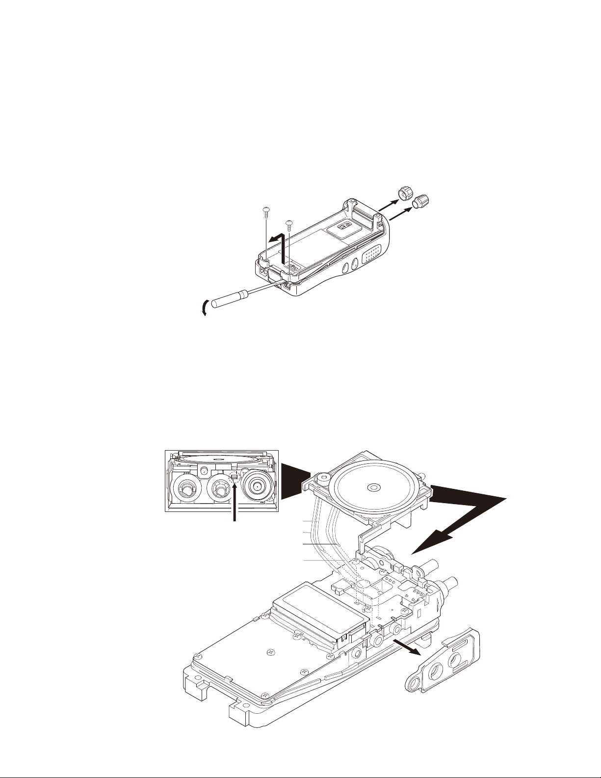
1. Removing the Case Assembly from the
Chassis
1. Remove the selector knoba and volume knob b.
2. Remove the two screws c.
3. Lift and remove the chassis from the case assembly d.
(Use a fl at-blade screwdriver to easily lift the chassis.)
c
c
d
2. Removing the Holder Assembly from
the Chassis
1. Remove the holder from the chassis.
Note: Taking care not to cut the speaker and microphone
lead.
2. Detach the solder of speaker and microphone lead from
the PCB beforehand.
3. Remove the packing e from the SP/MIC jack of the TX-
RX unit.
维修拆卸
1. 从机体上拆卸机壳
1. 拆卸选择器旋钮a和音量旋钮b。
2. 拧下 2 个螺丝c。
3. 从机体拉出并卸下机壳d。
(使用
2. 从机架卸下支架
1. 从机架卸下支架。
注意 : 小心不要折断扬声器引线和麦克风引线。
2. 卸下 PC 板上的扬声器引线和麦克风引线上的焊锡。
3. 卸下 SP/MIC 连接器的橡胶垫⑤。
一字
螺丝刀容易拉出机壳。)
a
b
Note: To remove the Holder Assy from
the Chassis,use a flat-blade screwdriver
and insert to this hole.
注意 : 从机架取下扬声器座时,请将
一字螺丝刀插入箭头所示位置。
BLU /
YEL /
BLK /
RED /
蓝色
黄色
黑色
红色
S-
M-
S+
M+
e
15
TK-2317
DISASSEMBLY FOR REPAIR /
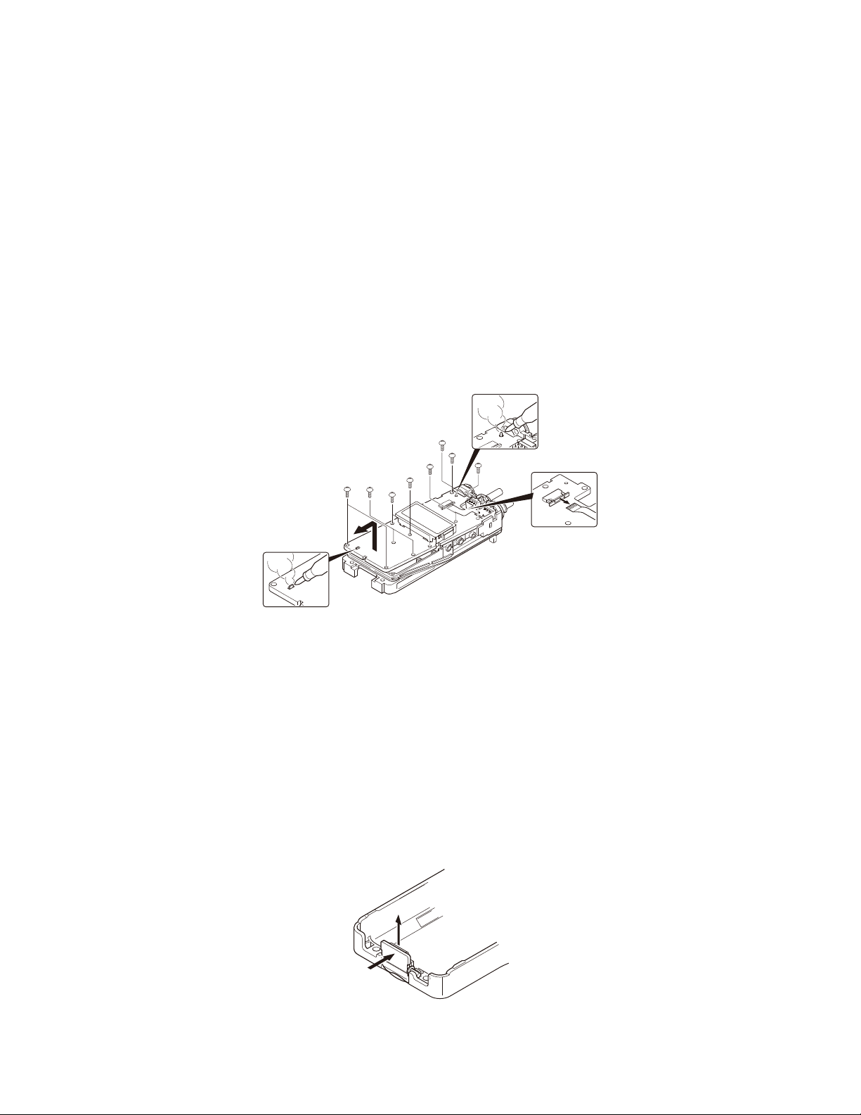
3. Removing the TX-RX unit from the
Chassis
1. Remove the eleven screws f fi xing the TX-RX unit.
2. Remove the solder of the antenna terminal with a solder-
ing iron g.
3. Remove the solder of the positive terminal with a solder-
ing iron h.
Note: You can remove the TX-RX unit from the chassis
without removing the solder at the positive terminal.
However, in this case, you can not attach the packing
(G53-1605-03) that is on the positive terminal to the
chassis in assembling. So, it is advisable to remove the
solder on the positive terminal fi rst.
4. Remove the FPC from the fl at cable connector i.
5. Lift and remove the TX-RX unit from the chassis j.
Bx2Bx2
Bx2
维修拆卸
3. 从机架拆卸收发单元
1. 卸下固定收发单元的 11 个螺丝f。
2.
用电烙铁烫开天线端子的焊锡。
3. 用电烙铁烫开电池正极端子的焊锡。
注∶不用烫下焊锡拆卸正极的端子,你也可以拆卸收发单
元。
但是组装时,正极端子连接的垫片 ( G53-1605-03) 不能安
装到机架。因此,请先烫开正极端子的焊锡。
4. 从扁平电缆连接器拆卸 FPC。
5. 从机架抬起收发单元。
B
B
B
B
B
>
j
g
h
i
2
4. Removing the Battery Release Lever
from the Case Assembly
1. Press the upper par t of the lever toward the inside of the
case assembly. One side of the shaft will be removed a.
2. Lift and remove the battery release lever from the case
assembly b.
Note: Scratch and widen the glue hole if there is diffi culty
in removing the other end of the shaft.
No glue is required when you reassemble the battery re-
lease lever.
@
8
4. 从机壳拆卸电池分离拨杆
1. 向机壳的内侧按压拨杆上部之后,就可以卸下轴的一侧。
a
2. 拿起电池分离杆,就可以从机壳上拆卸下来。
注∶如果很难拆卸轴的其它端部时,请刮掉和扩展粘合孔。
当你重新组装电池分离杆时,则不需要粘合。
b
16
:
TK-2317
DISASSEMBLY FOR REPAIR /
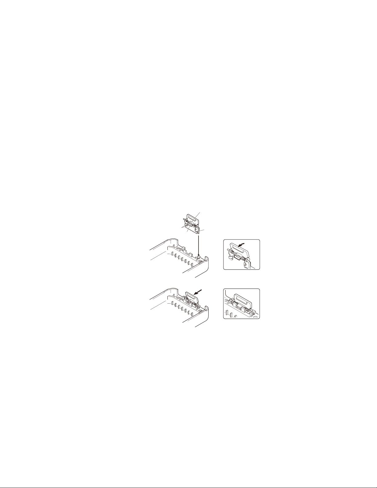
5. Attaching the Battery Release Lever to
the Case Assembly
1. Insert one side of the shaft into the hole at the lever fi tting
section on the case assembly a.
Caution: The thin spring (G01-4543-04) should be posi-
tioned above the two tabs of the lever.
2. Tilt the battery release lever slightly forward b, so that
the thick spring (G01-4542-04) is positioned below the
case surface.
3. With the thick spring positioned below the case surface,
attach the other side of the shaft to the case assembly
by pressing the battery release lever c until it snaps into
place d.
Caution: Be careful not to tilt the battery release lever
too forward.
If the battery release lever is pushed in this state where
the two tabs come below the case surface, there is a
possibility of damaging the two tabs.
维修拆卸
5. 安装电池分离拨杆到机壳
1. 把轴的一侧插入到机壳的拨杆安装部的孔里。
注∶细弹簧 (G01-4543-04) 必须安装到拨杆的 2 个突起上
面。
2. 轻轻地前推电池分离拨杆倾斜倒b,这样粗弹簧 (G014542-04) 就被定位在机壳下面。
3. 粗弹簧被定位到机壳下面之后,通过按电池分离拨杆c
直到它嵌入位置d,轴的另一侧接触机壳组件。
注∶注意不要把电池分离拨杆倾斜得太靠前。
如果电池分离拨杆被推到分离拨杆下面的 2 个卡头的位置,
就有可能损坏这 2 个卡头。
A thin spring /
细弹簧
a
Tow tabs /
A thick spring /
细弹簧
Shaft /
a
c
轴2 个突起的上侧
b
d
17
TK-2317
DISASSEMBLY FOR REPAIR /
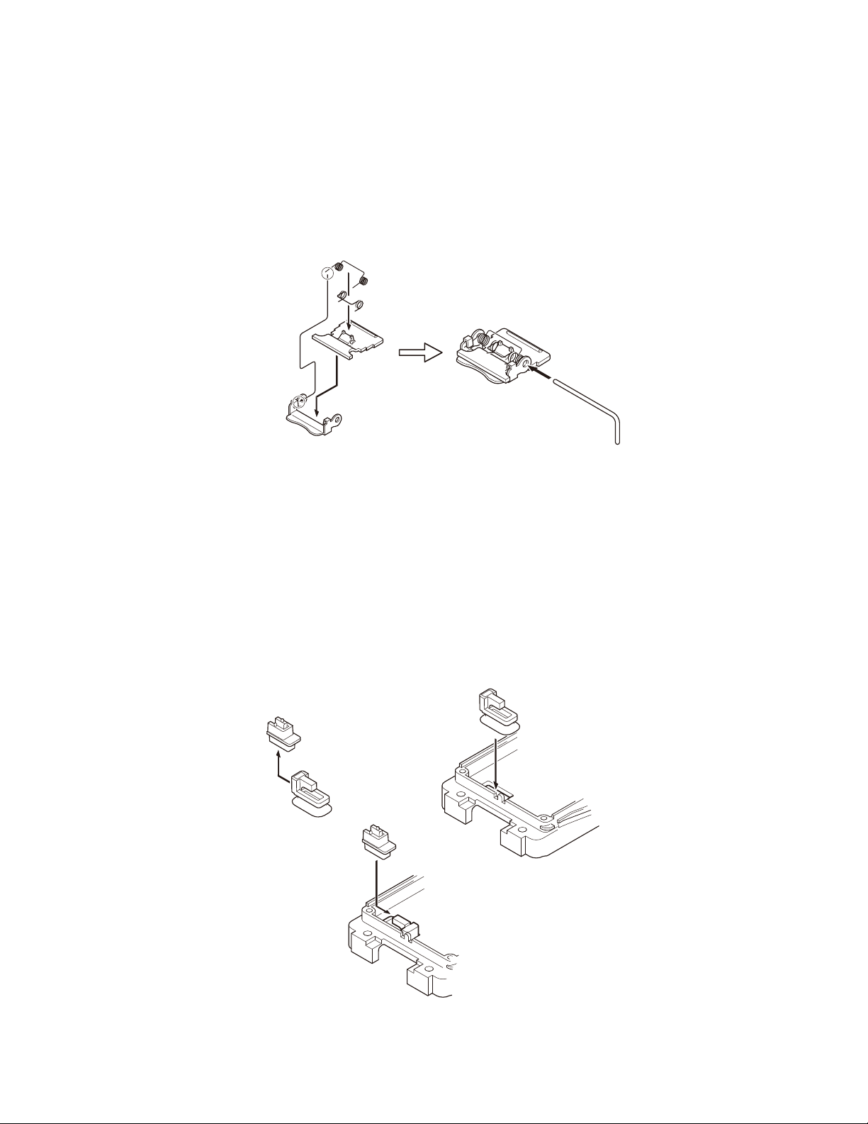
6. Assembling the Battery Release Lever
1. Place the lever b onto the stopper a.
2. Place the thick spring c onto the lever.
3. Hook the r ight and left ends of the thin spring d onto the
tabs of the stopper, then place the thin spring onto the
lever e.
4. Slide the shaft through the hole of the stopper and lever f.
d
c
e
b
维修拆卸
6. 电池分离拨杆的组装方法
1. 请把拨杆b置于止动器a的上面。
2. 请把粗弹簧c置于拨杆的上面。
3. 请把细弹簧置于拨杆上面,并让细弹簧d的左右端置于
止动器的两个卡头内。
4. 滑动轴穿过止动器和拨杆的孔。
f
e
f
7. Attaching the Positive Terminal to the
Chassis
Always attach the positive terminal to the chassis, using
the following procedures, before mounting the TX-RX unit
onto the chassis.
1. Remove the holder assembly b from the packing a of
the positive terminal.
2. Mount the packing of the positive terminal into the chas-
sis hole c.
3. Mount the holder assembly into the packing of the posi-
tive terminal d.
b
a
d
7. 把正极端子安装到机架
把收发单元组装到机架之前,必须按照以下的顺序把电池
正极端子安装到机架。
1. 从正极端子的垫片a上取下机架b。
2. 把正极端子的垫片安装到机架孔上。
3. 把支架安装到正极端子的垫片上。
c
c
d
18
TK-2317
DISASSEMBLY FOR REPAIR /
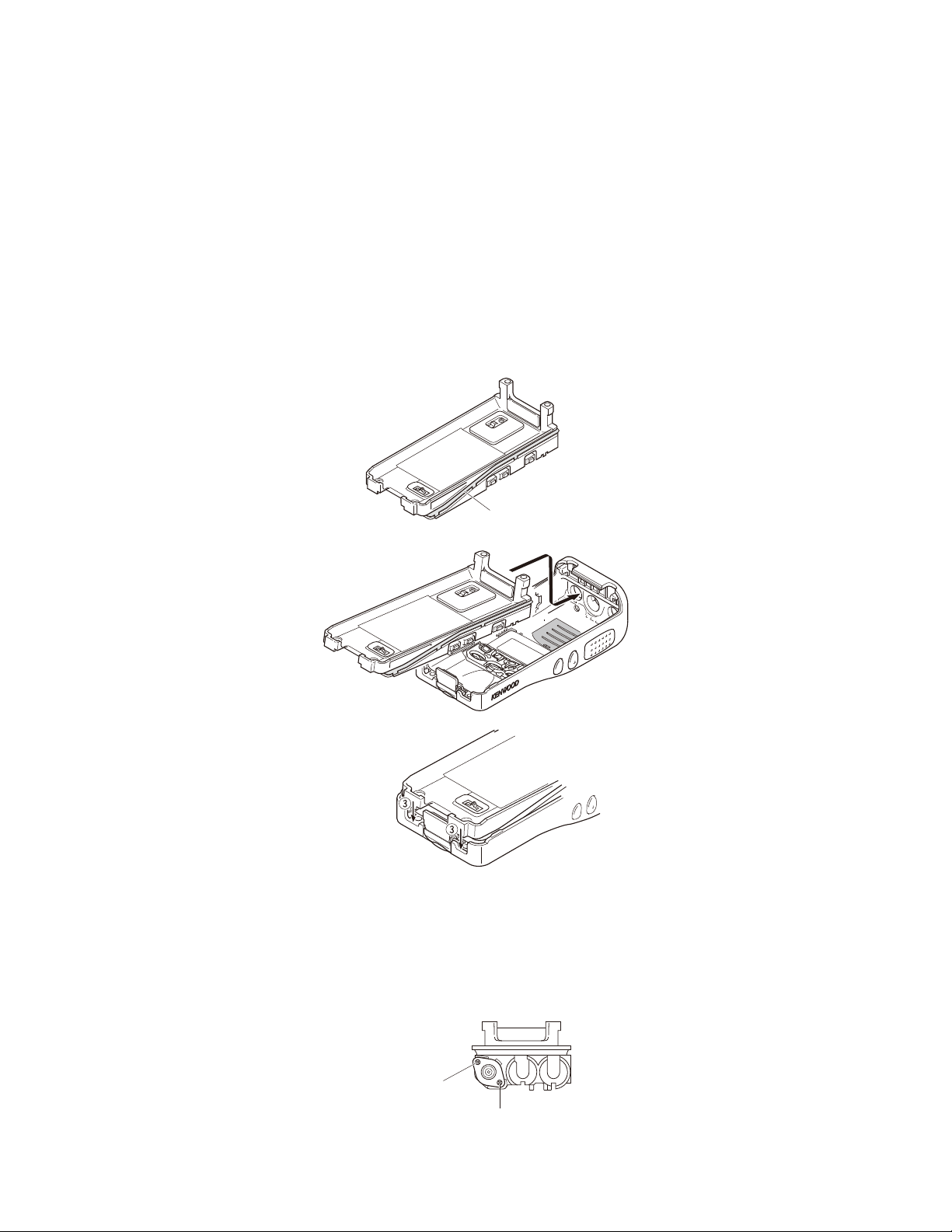
8. Mounting the Chassis to the Case
Assembly
1. Confirm that the waterproof packing attached to the
circumference of the chassis is securely inserted in the
groove of the chassis a.
2. Inser t the upper par t of the chassis into the case assembly b.
3. Press the chassis c and the case assembly together to
attach them.
Caution: If the packing of the SP/MIC does not come
to the correct position after attaching the chassis to the
case assembly, reposition the packing with your fi ngers.
维修拆卸
8. 安装机壳机架
1. 确认机架四周的防水垫是否确实进入机壳的槽里。
2. 把机架上部插到机壳里。
3. 按压机架c,使机架和机壳成为一个整体。
注∶把机架安装到机壳上后,如果 SP/MIC 不在正确的位
置的话,请用手指调整到正确的位置。
a
b
a
9. Attaching the Antenna Receptacle to
the Chassis
Screw the antenna receptacle to the chassis in the or-
der shown in the drawing so that the antenna receptacle
comes to the center of the case hole.
b
9. 把天线座安装到机架
为了能把天线座安装到机芯孔的中心,在将天线座安装到
机架时,请按照图示的顺序固定螺丝。
Tighten this screw second
然后再拧紧此螺丝。
Tighten this screw first.
首先拧紧此螺丝。
19
TK-2317
DISASSEMBLY FOR REPAIR /
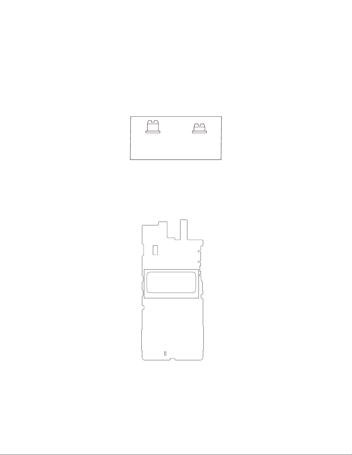
10. The Nuts of the Volume Knob and
Channel Knob
Note that the shapes, colors and heights of nuts of the
volume knob and selector knob are different from one
another. (The nut of volume knob is silver, and the nut of
selector knob is gold)
Use the following jig when removing the nuts of the vol-
ume knob and selector knob.
• Jig (Part No.: W05-1012-00)
for Volume knob
(Long)
音量旋钮的螺母
(长)
11. Screw sequence for mounting the TXRX unit to the chassis
Attach the TX-RX unit to the chassis using the screws in
the order shown in the drawing below.
维修拆卸
10. 关于音量旋钮和选择器旋钮的螺母
音量旋钮和选择器旋钮的螺母形状不同,颜色高度也不同,
因此请注意。( 音量旋钮螺母为银色,选择器旋钮的螺母
为金色 ) 另外,拆卸音量旋钮和选择器旋钮的螺母时,请
使用下列夹具。
•夹具 ( 零件号∶ W05-1012-00)
for Selector knob
(Short)
选择器旋钮的螺母
(短)
11. 安装收发单元到机架上的螺钉顺序
利用下图所示的螺钉顺序安装收发单元到机架上。
k
j
TX-RX UNIT
Component side view
i
d
a
eb
fc
gh
20
TK-2317
CIRCUIT DESCRIPTION /
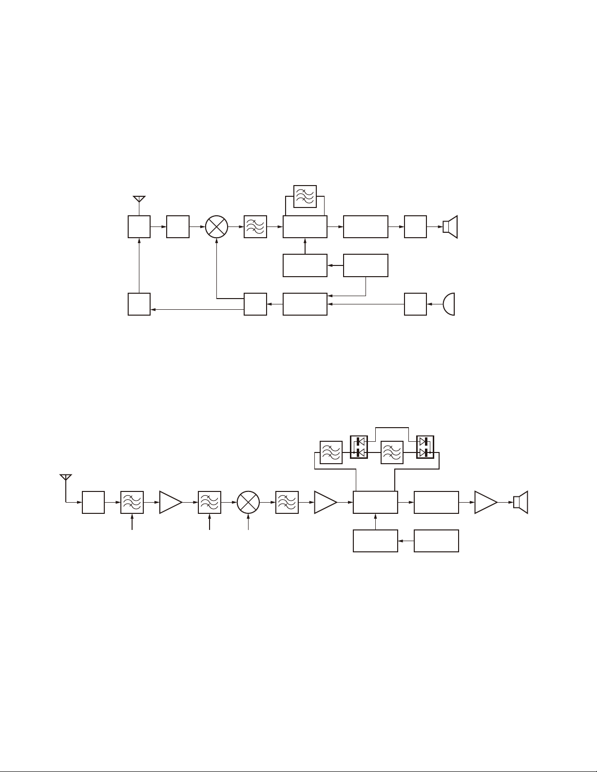
1. Frequency Confi guration
The receiver utilizes double conversion. The first IF is
49.95MHz and the second IF is 450kHz. The fi rst Local oscillator is supplied from the PLL circuit.
The PLL circuit in the transmitter generates the neces-
sary frequencies.
TX/RX: 136~174MHz
ANT
1st MIX MCF SP
ANT
SW
TX
AMP
RF
AMP
136~174MHz
49.95MHz
185.95~
223.95MHz
RF
AMP
电路说明
1. 频率构成
接收部采用二次变频超外差方式。第一中频为 49.95MHz,
第二中频为 450kHz。第一本振频率信号由锁相环电路提供。
发射部由锁相环电路直接产生所需的频率。图 1 显示各种
频率。
CF
450kHz
IF
System
50.4MHz
X3
multiply
PLL
VCO
AF
baseband
TCXO 16.8MHz
AF
AMP
MIC
MIC
AMP
Fig. 1 Frequency confi guration /
2. Receiver System
The receiver system is shown in Figure 2.
ANT
BPF
ANT
SW
BPF1
2-1. Front End (RF Amplifi er) Circuit
The signal coming from the antenna passes through the
transmit / receive switching diode circuit (D201, D202, D203
and D204) and a BPF (L418 and L419), and is then amplifi ed by the RF amplifi er (Q407).
The resulting signal passes through a BPF (L419, L418,
L416 and L414) and goes to the mixer. These BPFs are adjusted by variable capacitance diodes (D408, D407, D405
and D404). The input voltage to the variable capacitance
diodes is a regulated voltage output from the DC amplifi er
(IC811).
Q407
RF AMP XF401
BPF
BPF1 1st Local
Q406
1st MIX
MCF
Fig. 2 Receiver system /
图 1 频率构成
2. 接收部系统
接收部系统的如图 2 所示。
CF402 CF401
Q405
IF AMP
IC401
IF,MIX,DET
Q403
X3 multiply
2nd Local
IC812
AF
baseband
X1
TCXO
16.8MHz
图 2 接收部系统
2-1. 前级 ( 射频放大器 ) 电路
从天线接收的信号进入发送 / 接收转换开关二极管电路
(D201、D202、D203 和 D204),然后通过 BPF(L418 和 L419),
并且被射频放大器 (Q407) 放大。
此信号通过 BPF(L419,L418,L416 和 L414) 然后进入混频。
这些 BPF 被可变电容器 (D408,D407,D405 和 D404) 调整。输
入可变电容器的电压被经直流放大器 (IC811) 的电压输出调
整。
IC815
AF PA
SP
21
 Loading...