

POWERED SUBWOOFER
103SW/SW-301
1050SW/SW-501
SERVICE MANUAL
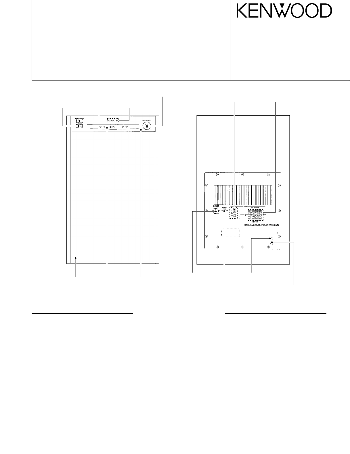
Knob
(K29-0573-08)
Knob
(K29-0577-08)
Knob
(K29-0578-08)
KENWOOD badge
(B43-0302-04)
©1997-10/B51-5376-00 (K/K) 2295
RCA pin jack
(E23-0224-08)
Speaker terminal
(E21-0279-08)
Cloth frame assy
(B06-1144-08)
Note : Refer to SW-900 service manual(B51-4228-00) if you need
the microprocessor information.
Window
(B10-3302-08)
Panel *
(A29-)
Knob
(K29-0576-08)
Slide switch
(S62-0207-08)
Power cord bushing
(J42-0234-08)
* Refer to parts list on page 8.
SPECIFICATIONS
Amplifier
Power output 150 watts RMS into 4 ohms, 100 watts RMS into 4 ohms,
Phase switching Normal, Reverse Normal, Reverse
Input sensitivity and input impedance
RCA-type jack 70 mV (12 k-ohms) 70 mV (12 k-ohms)
Push-type terminals 1.7 V(15 k-ohms) 1.7 V(15 k-ohms)
Supply voltage AC 110 V~120 V (1050SW) AC 110 V~120 V(103SW)
Rated power consumption 150 watts 110 watts
Speaker
Enclosure Ported Ported
Speaker units 12 in (300 mm) polypropylene 10 in (250 mm) polypropylene
Nominal impedance 4 ohms 4 ohms
Width 14.3 in (363 mm) 11.8 in (300 mm)
Height 21.7 in (550 mm) 18.9 in (480 mm)
Depth 18.9 in (480 mm) with grille 15.6 in (395 mm)
Net weight 53 lb (24 kg) 40 lb (18 kg)
Since Kenwood follows a policy of continuous advancement in development, these specifications may change without notice.
1050SW(SW-501) 103SW(SW-301)
from 20 Hz to 200 Hz, with no from 20 Hz to 200 Hz,with no
more than 0.09%total more than 0.09%total
harmonic distortion harmonic distortion
cone cone
AC power cord*
(E30-)

103SW/SW-301/1050SW/SW-501
1
1
2
3
x3
Dc voltmeter
5 mV
R611
(a)
No.
ITEM
INPUT
SETTINGS
OUTPUT
SETTINGS
AMPLIFIER
SETTINGS
ALIGNMENT
POINTS
ALIGN FOR
FIG.
Unless otherwise specified, the individual switches should be set as following :
POWER : ON NO SIGNAL INPUT
1
IDLE CURRENT
–
Connect a DC
voltmeter to
R611
VOLUME : 0
VR601
5 mV
(a)
CONTENTS/DISASSEMBLY FOR REPAIR/ADJUSTMENT
Contents
SPECIFICATIONS........................................Top cover
CONTENTS ............................................................... 2
DISASSEMBLY FOR REPAIR....................................2
ADJUSTMENT............................................................2
DISASSEMBLY FOR REPAIR
< How to remove the front panel >
1. Remove the decoration plate (1) by a pincette to the bottom of
the front panel, then remove the 3 screws (2).
2. 103SW/SW-301: Remove the front panel in the upper slanting
direction of the arrow (3).
1050SW/SW-501 : Remove the front panel just the frontwards.
PC BOARD ................................................................ 3
SCHEMATIC DIAGRAM............................................ 5
EXPLODED VIEW ......................................................7
PARTS LIST................................................................8
ADJUSTMENT
2

ACEGIBDFHJ
PC BOARD(Component side view
1
2
3
)
4
5
6
7
Refer to the schematic diagram for the value of resistors and capacitors.
3 4

A B D F H JC E G I
X
X
X
X
X
X
X
X
F904
T1,6AL
250V
C903
0.047
C902
0.047
INPUT/FILTER (210-6415-160)
+15V
100P
R112 5.6K
C106 22P
270K
C208
0.18
R208
12
C.D C.A
3
C217 0.01
7
R408 100K
R409 100K
302928
TSW5(B.BST)
TSW4(PHASE)
S.BOOST
POWER
121011
0V
0V
5.0V
R417 100K
R416 100K
IC441
RESET IC
3
-
2
+
C207
C206+
6.8K
13
2
R221
4.7K
C218
(
25
(
26
R407 100K
TSW3(SUBSD)
SI
SO
0V
R415 100K
AMP
1
IC101
(2/2)
270K
R207
14
VDDSWDSWC
1
-5V
R222
9.1K
0.047
)
)
R406 100K
27
TSW2(TURND)
5.0V
SCK
0V
R414 100K
C107
47u16
+
C205
0.180.18
5.2V
VR201C
50K
R405
26
TSW1(POWER)
INT
1617141513
0V
0V
R412 100K
R413 100K
+5V+5V
C204
R206
R223
120K
100K
TIO
R111
22K
C108
C101
33u16
+
-15V
R209
IC201
(2/2)
6
-
7
5
+
11
1089
SWB SWA
5
4
IC203
(2/2)
5
+
6
-
C215
0.027
R220 100 R226
50K Cx4
100K
R410
5.0V
31
33
32
34
ILL
T.04
T.05
T.02
T.03
5.0V
SUBSONIC
REV
896
0V
0V
R420 100K
R418 100K
R419 100K
)
)
ZD101
8.2K
220P
R109
C211
0.01100P
IC202
(1/2)
1
-15.5V
4
-15V
MODE SW
-15V
(BOTTOM VIEW)
R216
9.1K
VR201A
50K
C103
15.2V
8
-
R212
33K
IC204
-15V
100P
R217
220K
15.2V
ZD102
3
2
C214
5
+
6
-
R110 5.6K
C104 220P
C210
0.12
8
4
100P
VSS
7
-5.1V
R218
9.1K
C105
0.01
7
IC101
(1/2)
-15.5V
R210
160K
C209
0.033
R211
27K
R213
180K
C.C C.B
6
R219
220K
VR201B
50K
1
2
3
SP
INPUT
(FROM AMP)
TO SP
LINE
INPUT
(210-6415-140)
SPK JACK
JK101
Lch
Rch
Lch
Rch
JK102
R105
1
2
3
220P
C228
4
5
6
7
8
2
Lch
1
3
Rch
R104
R113
R115
12K
1K
220P
C227
R114
220P
C226
12K
100K
R107
4.7K
100K
220P
C229
R101
R108
100K
R106
4.7K
100K
R102
1.2K
1.2K
1/2W
1/2W
C102
R103
C212
+15V
4.7K
R215C213
0.047
STAND-BY
SW401
21
W401
4
CN401A
12 123
)()
25
26
(
5
DESTINATION
6
COUNTRY ABB
USA K 0.047UF/0.056UF 0.047UF/0.039UF 100U10/220U16 3.15A/4A 0.8A/0.8A -/- 12K/27K 1K/820 -/1K 220K/270K
CANADA P 0.047UF/0.056UF 0.047UF/0.039UF 100U10/220U16 3.15A/4A 0.8A/0.8A -/- 12K/27K 1K/820 -/1K 220K/270K
EUROPE E 0.047UF/0.056UF 0.047UF/0.039UF 100U10/220U16 1.6A/2A 0.8A/0.8A -/- 12K/27K 1K/820 -/1K 220K/270K
ENGLAND T 0.047UF/0.056UF 0.047UF/0.039UF 100U10/220U16 1.6A/2A 0.8A/0.8A -/- 12K/27K 1K/820 -/1K 220K/270K
GERMANY G 0.047UF/0.056UF 0.047UF/0.039UF 100U10/220U16 1.6A/2A 0.8A/0.8A -/- 12K/27K 1K/820 -/1K 220K/270K
AUSTRALIA X 0.047UF/0.056UF 0.047UF/0.039UF 100U10/220U16 1.6A/2A 0.4A/0.4A -/- 12K/27K 1K/820 -/1K 180K/180K
CHINA C 0.047UF/- 0.047UF/- 100U10/- 1.6A/- 0.4A/- -/- 12K/- 1K/- -/- 180K/GENERAL MARKET M 0.047UF/0.056UF 0.047UF/0.039UF 100U10/220U16 1.6A/2A 0.4A/0.4A 1.6A/2A 12K/27K 1K/820 -/1K 180K/180K
MALAYSIA I 0.047UF/0.056UF 0.047UF/0.039UF 100U10/220U16 1.6A/2A 0.4A/0.4A 1.6A/2A 12K/27K 1K/820 -/1K 180K/180K
PX Y 0.047UF/- 0.047UF/- 100U10/- 1.6A/- 0.8A/- 1.6A/- 12K/- 1K/- -/- 220K/JAPAN J 0.047UF/0.056UF 0.047UF/0.039UF 100U10/220U16 3.15A/4A 0.4A/0.4A -/- 12K/27K 1K/820 -/1K 15K/18K
+15V
D GIND
CONT.B
CONT.A
1234
)
)
9
10
(
(
+5V
D414
D415
C204 C207 C631 F901 F902,3 F904 R206 R603 R606 R613
CN201C
+5V +5V
5V AVR
15.3V
IC403
1
VDVI
GND
2
0.1
C401
D413
5.0V
C442
R441
4.7u25
1K
+
R445
10K
U-COM (210-6415-130)
+5V
5.6V
3
C402
RESET
2200u10
+
0.1
Q441
R442
4.7K
C443
+5V
+
C403
47u10
42
R443 10K
C404 1000P
D412
(
()(
383940
)
)
1.4V
4.4V
0.2V
394038
353637
T.01
REV
NOR
SUBSO
ILL
SP
X2
7
5.0V
5.0V
31
R422 100K
R421 100K
5.0V
(
9
(
10
41
VOL
VSS
S.BST
2.4V
X1 RESET
45231
X401
4.19MHz
2.3V
IC441
IN
OUT
GND
2
5.0V
R444 10K
Note: 103SW(SW-301)/1050SW(SW-501)
CAUTION: For continued safety, replace safety critical components only with manufacturer's
recommended parts (refer to parts list). indicates safety critical components. For continued
protection against risk of fire, replace only with same type and rating fuse(s). To reduce the risk
7
of electric shock, leakage-current or resistance measurements shall be carried out (exposed
parts are acceptably insulated from the supply circuit) before the appliance is returned to the
customer.
C202
R202
47K
220K
R201
C201
100P0.01
8
3
+
1
2
-
IC201
4
(1/2)
-15.5V
R204
47K
47K
R203
-15V
C203
R205
100
0.18
+15V
15V AVR
1K
R878R877
+5V
C240
100P
+
C878
47u10
+
C877
47u10
-15V
-5V
C876
47u25
ZD874ZD873
C875
47u25
-5V
-5V
1K
-15V
-15V AVR
+5V
IC204 MODE
MOVIE
REV
15.2V
IC203
R225
VR201D
(1/2)
120K
50K
C220
0.039
R224
9.1K
0.12
C219
C241 0.01
5.2V
12
5136
,,
BAMODE
XXHLMUSIC
LHXXNOR
-15.5V
C221
8
3
2
1u50
+
1
+
4
100
47K
R228
10K
-5V
Q254
R260
CROSSOVER
SLOPE
-24dB
-12dB
1u50
R227
C222
+
R256R258
1K
Q254
10K
CONT.
A
1K
R229
SW201
47K
15.2V
21.3V
X
Q872
R872
1W
1K
15.8V
C874
R876
470
R875
470
R251
Q251
IC202
(2/2)
1K
ZD872ZD871
1K
R873 R874
-24.9V
R253
CONT.
B
+V-V
X
R871
1W
10K
1K
R252
R254
10K
Q252
C224
10u25
7
+
100K
R232
220P
+
+
C872
100u25
+
+
C871
100u25
C873
220P
-16.1V
-15V
-15.5V
Q871
MUS:5.2V
MOV:0V
5.2V
R255R257
1K
10K
Q253
NOR:5.2V
REV:0V
10K
R259
BUFFER
5
+
6
-
R231 5.6K
+
220K
R235
C223
10u25
1.5K
R230
CROSSOVER FREQUENCY(REAR)
PEAK
POWER
MUTE
+5V
100K
100K
R401
R402
100K
100K
R403
R404
25
TEST
0V
R411 100K
0V
5.0V5.0V
4.9V
POWER
5.0V
CE
18
C406
0.047
R438 1K
C407
0.047
IC404
REMOTE SENSOR
82K/120K 18K/22K 820/1.5K 4.7/4.7 220/- 4.7/- 4.7/- X/X D3SBA20/D5SBA20 2SC5198/2SC3281 (R) 2SA1941 (R) /2SA1302 (R)
82K/120K 18K/22K 820/1.5K 4.7/4.7 220/- 4.7/- 4.7/- X/X D3SBA20/D5SBA20 2SC5198/2SC3281 (R) 2SA1941 (R) /2SA1302 (R)
82K/120K 18K/22K 820/1.5K 4.7/4.7 220/- 220/- 10/- X/X D3SBA20/D5SBA20 2SC5198/2SC3281 (R) 2SA1941 (R) /2SA1302 (R)
82K/120K 18K/22K 820/1.5K 4.7/4.7 220/- 220/- 10/- X/X D3SBA20/D5SBA20 2SC5198/2SC3281 (R) 2SA1941 (R) /2SA1302 (R)
82K/120K 18K/22K 820/1.5K 4.7/4.7 220/- 220/- 10/- X/X D3SBA20/D5SBA20 2SC5198/2SC3281 (R) 2SA1941 (R) /2SA1302 (R)
82K/120K 15K/18K 560/- -/- 180/- 4.7/- 4.7/- X/X D3SBA20/D5SBA20 2SC5198/2SC3281 (R) 2SA1941 (R) /2SA1302 (R)
56K/75K 15K/18K 560/- -/- 180/- 4.7/- 4.7/- O/O D3SBA20/D5SBA20 2SC5198/2SC3281 (R) 2SA1941 (R) /2SA1302 (R)
56K75K 15K/18K 560/- -/- 180/- 4.7/- 4.7/- O/O D3SBA20/D5SBA20 2SC5198/2SC3281 (R) 2SA1941 (R) /2SA1302 (R)
56K/75K 15K/18K 270/270 -/- 180/180 4.7/4.7 4.7/4.7 X/X D3SBA20/D5SBA20 2SC5198/2SC3281 (R) 2SA1941 (R) /2SA1302 (R)
0V
222423
IC401
+5V
VOL.UP
0V
NC
VOL.DOWN
VDD
211920
u-COM
MUTE
REMOTE
IC404
VOG
5.0V
C405
D416
D417
0.1
R614 R631 R663 R801,2 R851 R871 R872 SW902A D801 Q602 Q603
56K/- 15K/- 560/- -/- 180/- 4.7/- 4.7/- X/- D3SBA20/- 2SC5198/- 2SA1941 (R) /-
82K/- 18K/- 820/- 4.7- 220/- 220- 10/- O/- D3SBA20/- 2SC5198/- 2SA1941 (R) /-
VOLUME
MOTOR
DRIVE
IC402
UP
UP
7.1V6.6V
5
312
4
R433
100
R434
100
0V
0V
6.6V
15.3V
R432
4.7K
C410
0.01
ZD401
867
15.3V
R431
2.2
9
10
DOWN 8.0V
DOWN 6.7V
D411
(
38
(
39
(
40
D418
R439 4.7K
0.7V
)
)
R428
10K
R436
)
LAMP
ON/OFF
The DC voltage is an actual reading measured with
a high impedance type voltmeter. The measurement
value may vary depending on the measuring
instruments used or on the product.
R233
R437
1K
PEAK
1K
1K
NOR
REV
0.3V
W802
3
2
1
R234
100K
Q403
R440
+V
GND
-V
+15V
C225
0.047
LED ON/OFF
10K
D403
D401
D402
Q402
1.0V
LAMP
CONT.
1.8V
STAND-BY
R427
2.0V
R429
D404
GREEN
330
R423
R424
L401
MOVIE
Q401
10K
R430
0.4V
1K
CN201A
+15V
7
GND
6
CONT.B
5
CONT.A
4
SOUT
3
GND
2
SIN
1
W601
SIN
1
GND
2
DET
3
+15V
270
R435
560
560
L402
15.4V
MUSIC
0.3V
+
C408
470u10
TC4066BP
R425
D419
POWER AMP (210-6415-110)
CN803A
PEAK
3
POWER
2
4.9V
R621
MUTE
CN601
CN802
AC-L2
D GND
AC-L1
AC-H2
AC-H2
AC-H1
AC-H1
CN801
+5V
+15V
39
R426
39
0.3V
0.8V
Q405
CN402A
3
2
1
220K
1
S IN
1
GND
2
DET
3
+V
3
GND
2
-V
1
0.01
C808
9
8
7
6
5
4
GND
3
GND
2
1
LGND
AC-L2
CCW
CW
GND
MUTE
DRIVE
R851
RY851
AC-L1
Q621
1W
POWER
ON/OFF
AC-H2
R802
R801
D851
1W
1W
X
X
-7.8V
5.1V
D811
D812
C802 C801
GND
800MA 250V
800MA 250V
W402
CCW
GND
2SA1015GR
R622
22K 22K
1u50
220K
C621
R625
+V
C812C811
2200u25
2200u25
D813
RELAY
ON/OFF
D814
X
D801
0.01
~
~
0.01
W801CN803B
123456789
AC-H1
F902
F903
MOTOR
VOLUME
3
2
CW
C411
1
R633 270
4.5V
R623
-7.8V
R624
100K
+
MUTE
Q622
IC851
C851
1u50
0.6V
+
R811
1.5K
1/4W
+
D815
C813 100u25
-V
+
R854
+
10K
Q851
0V
C806
0.01
10000u
+-
0.01
C804 C803
D651
R651
22K
+
C651
4.7u50
TRANSFORMER
210-6415-120
X
SW902A
USED
(M,I,Y) TYPE
0.01
120V
T1
S5
S4
S3
S2
TH
S1
MVR401
M
UPD75004CU-076
Q631
R632
C601
10u25
0.7V
1
10000u
++
1K
X
C805
+
6363
B
0V
R603
C852
240V
3
2
1
+
C631
R601
1K
PROTECT IC
0.5V
1000P
-VCC
F901
CN201B
SOUT
GND
SIN
X
R631
100P
C602
+
C853 2200u16
D853
DC
DETECT
Q652
1
2
47K
R602
5.1V0.4V
5.1V
0.2V
D852
A
0V
R652
C659
1
2
D631
C612
0.047
PRE
DRIVE
IC
0V
C603
100u25
+
8765432
R853
2.7K
R855
2.7K
R852
4.7K
R655
2.7K
C660
+VCC
1u50
+
R656
47K
A
-0.4V
33K
R653
22K
+
22K
R654
22u16
210-6415-150
+2.1V
R664
R657
-6.3V
4
5
B
470K
68K
C901
4700P
SW901
16K
R604
A
3
2
IC601
7
6
100P
C604
0.5V
1
0V
C655
C606
100u63
1
8
2.7K
R605
1K
R606
1K
VR601
OFFSET
VOL.DET.
2
0V
47u10
AC SW
R608
Q602,603
+
10 1/4W
R610
A
2.7
1/4W
0.3V
0.5V
14
13
12
11
10
-0.5V
9
R609
B
2.7
1/4W
-0.3V
100P
C605
Q601
-0.7V
C607
IDLE
100u63
-1.3V
ADJ.
DET.
AUTO RECOVERY
LATCH SW
IC651
SP
RELAY
DRIVE
CN901
1
2
(K,P)
: AC120V 60Hz
: AC110-120V
(Y,M,I)
/220-240V~
50/60Hz
(C)
: AC220V~ 50Hz
: AC240V~ 50Hz
(X)
: AC230V~ 50Hz
(T,E,G)
FINAL TR.
X
Q602
A
C608
100P
+
5W x 2
R611 0.22
C611 1u50
C609
100P
0V
X
Q603
R607 10
1/4W
B
R613
+
-VCC
+VCC
VCC ONOVER LOAD
MUTE
FLIP-
FLOP
AC OFF
DET.
3
4
2.3V
Q251,252,401-403,405,441,631,651,851
4.7K
R660
+VCC
0V
R612
10 1W
C610
0.047
RELAY
DRIVER
6
5
0.7V
C656
103SW/SW-301
1050SW/SW-501
UPC1237HA 78L05A LB1641
1K
R661
SP
ON/OFF
X
R663
1W
2.2V
7
R659
+
22u16
R615 10K
X
R614
C652
2.2u50
3.5V
VCC
8
LIMIT
Q651
0V
+
RY601
D653
R658
12K56K
: NJM4558LIC101,201-203
: TC4066BPIC204
: uPD75004CU-076IC401
: LB1641IC402
: 78L05AIC403
: W02-3003-08IC404
: PST600C.IC441
: uPC1298VIC601
: uPC1237HAIC651
: NJM2072DIC851
: 2SC1815GR
: 2SA1015GRQ253,254,621,652
: 2SC1846Q601
:Q602
:Q603
: 2SC2878AQ622
: 2SB1274Q871
: 2SD1913Q872
:D801
: MTZJ30BZD101,102
-0.4V
A
10K
R662
0V
SP+
D652
SP+
GND
1
2
3
CN804
WOOFER
+
-
SP OUTPUT
103
SPK1
24.5V/4 1050
20V/4
,BA VOLTAGE
A
B
-46.3V
46.2V
103
-56.4V
55.8V
1050
X
X
B30-1820-08:D401,402
B30-1821-08:D403
B30-1822-08:D404
1SS133:D411,412,414-419,631,852,853
1SR139-100:D413,651-653,811-814,851
X
MTZJ6.8B:ZD401
MTZJ5.1B:D815,ZD873,874
MTZ16B:ZD871,872
NJM4558L
UPC1298VPST600C
2SC2878A
2SC1846
2SB1274
2SD1913
103SW/SW-301/1050SW/SW-501
Y19-3900-10

1050/103SW
770
620
660
600
643
643
103SW/SW-301
633
621
641
632
MVR401
642
642
603
603
640
640
611
SPK1
630
x2
612
612
601
604
601
602
602
613
613
607
Gx2
Gx2
Dx2
Mx2
Mx2
Ex2
Ex2
771
771
771
630x2
771
782x2
M
M
MVR401
Dx2
Cx8
759
759
780
777
Jx6
771
773
781
Ax3
L
Ax3
Ax3
Ax3
Hx2
Lx2
Nx2
Nx2
Jx2
Jx2
F
F
K
K
K
K
775
774
772
776
778
779
7P
(CN201A)
3P
(CN804)
Bx2
Bx2
650
A
B
C
C
D
D
E
F
G
H
J
K
L
M
N
ø 4x14(BLK)
M4x16
ø 5x25(BLK)
ø 5x25(BLK)
ø 3x20(BLK)
ø 3x16(BLK)
ø 3x8
ø 3x6
ø 3x8
ø 3x10(BLK)
ø 3x8(BLK)
ø 3x10(BLK)
ø 3x10(BLK)
ø 3x8
ø 3x8
:
:
:
:
:
:
:
:
:
:
:
:
:
:
:
N44-4014-45
N35-4016-45
N09-3668-05
(103SW)
N09-3672-05(1050SW)
N44-3020-45(103SW)
N62-3116-45(1050SW)
N09-3669-05
N89-3006-46
N83-3008-46
N89-3010-45
N89-3008-45
N34-3010-45
N82-3010-45
N82-3008-46
N89-3008-46
625
625
622
Parts with exploded numbers larger than 700 are not supplied.
A
B
C
1
EXPLODED VIEW (UNIT)
103SW/SW-301/1050SW/SW-501
2
7

8
✽ New Parts
Parts without Parts No. are not supplied.
Les articles non mentionnes dans le Parts No. ne sont pas fournis.
Teile ohne Parts No. werden nicht geliefert.
Add-
Ref. No
ress
New
Parts
Parts No.
Description
103SW/SW-301 (103SW: KP type only)
600 1A ✽ A09-0753-05 BATTERY COVER
601 2A ✽ A29-0915-08 PVC TRIM FOR WINDOW
602 2A ✽ A29-0917-08 PVC TRIM FOR PANEL TOP
603 1A ✽ A29-0919-08 PANEL TOP W/PAINTING & LOGO KP
603 1A ✽ A29-0920-08 PANEL TOP W/PAINTING & LOGO MICTEG
603 1A ✽ A29-0920-08 PANEL TOP W/PAINTING & LOGO XY
607 1A ✽ A70-0404-05 REMOTE CONTROL ASSY
611 2A ✽ B06-1144-08 CLOTH FRAME ASSY
612 2A ✽ B10-3302-08 WINDOW
613 2A B43-0302-04 BADGE
620 1A E03-0115-05 AC PLUG ADAPTER MIY
621 1B ✽ E30-5432-08 AC CORD,181-SA-W541 KP
621 1B ✽ E30-5438-08 AC CORD MIEGY
621 1B ✽ E30-5439-08 AC CORD X
621 1B ✽ E30-5440-08 AC CORD T
621 1B ✽ E30-5442-08 AC CORD C
622 1C ✽ E30-5466-08 AUDIO CORD
625 1C F20-0702-08 ISOLATION SHEET 19X24
630 2A,2B J19-3988-08 CATCH BLACK(75)
632 1B J21-8750-08 AC CORD HOLDER
633 1B ✽ J42-0234-08 CORD BUSHING,3-703-244-021
640 2A ✽ K29-0573-08 VOLUME KNOB W/PAINTING
641 1C ✽ K29-0576-08 LOW/PASS PUSH KNOB W/PAINTING
642 1A ✽ K29-0577-08 POWER PUSH KNOB W/PAINTING
643 1A ✽ K29-0578-08 TACT PUSH KNOB W/PAINTING
650 2C ✽ L07-3010-05 POWER TRANSFORMER KP
650 2C ✽ L07-3011-05 POWER TRANSFORMER MIY
650 2C ✽ L07-3012-05 POWER TRANSFORMER C
650 2C ✽ L07-3013-05 POWER TRANSFORMER TEG
650 2C ✽ L07-3014-05 POWER TRANSFORMER X
660 1A ✽ J02-0622-08 FOOT
- B46-0096-53 WARRANTY CARD X
- B46-0310-03 WARRANTY CARD TEG
- B46-0326-03 WARRANTY CARD C
- B46-0330-03 WARRANTY CARD KY
- B59-1104-00 SERVICE STATIONS LIST Y
- ✽ B61-0886-00 INSTRUCTION MANUAL KP
- ✽ B61-0887-00 INSTRUCTION MANUAL MIXY
- ✽ B61-0888-00 INSTRUCTION MANUAL TEG
- ✽ B61-0889-00 INSTRUCTION MANUAL C
- ✽ B61-0940-00 INSTRUCTION MANUAL Y
- ✽ H10-6447-08 PLYFOAM 310G/SET(TOP)
- ✽ H10-6448-08 PLYFOAM 310G/SET(BOTTOM)
- ✽ H21-1284-08 MIRAMAT 1640X540X0.5T
- ✽ H25-2180-08 PROTECTION BAG CY
- ✽ H51-0979-08 CARTON KP
- ✽ H51-0980-08 CARTON MIY
- ✽ H51-0981-08 CARTON C
- ✽ H51-0982-08 CARTON TEGX
A N44-4014-45 WOOD SCREW
B N35-4016-45 MACHINE SCREW(M4X16)
C ✽ N09-3668-05 WOOD SCREW
D N44-3020-45 WOOD SCREW
✽ New Parts
Parts without Parts No. are not supplied.
1 2
Re-
Desti-
marks
nation
Les articles non mentionnes dans le Parts No. ne sont pas fournis.
Teile ohne Parts No. werden nicht geliefert.
Add-
Ref. No
E ✽ N09-3669-05 SCREW
F N89-3006-46 SCREW
G N83-3008-46 SCREW
H N89-3010-45 SCREW
J N89-3008-45 SCREW
K ✽ N34-3010-45 SCREW
L N82-3010-45 SCREW
M N82-3008-46 SCREW
N N89-3008-46 SCREW
SPK1 2A ✽ T10-0782-15 SPEAKER 10,A25GU25-51C-D KP
SPK1 2A ✽ T10-0788-05 SPEAKER 10 MIXY
SPK1 2A ✽ T10-0814-05 SPEAKER 10 C
SPK1 2A ✽ T10-0822-05 SPEAKER 10 TEG
ress
New
Parts
Parts No.
Description
1050SW/SW-501 (1050 SW: KP type only)
600 1A A09-0753-05 BATTERY COVER
601 1B A29-0915-08 PVC TRIM FOR WINDOW
602 1A ✽ A29-0916-08 PVC TRIM FOR PANEL
603 1A ✽ A29-0909-08 PANEL KP
603 1A ✽ A29-0921-08 PANEL MIETGX
604 1B ✽ A29-0922-08 PANEL ,FRONT
607 1A A70-0404-05 REMOTE CONTROL ASSY
611 2A ✽ B06-1146-08 CLOTH FRAME ASSY
612 1B B10-3302-08 WINDOW
613 1A B43-0302-04 BADGE
620 2A E03-0115-05 AC PLUG ADAPTER MI
621 1B E30-5432-08 AC CORD,181-SA-W541 KP
621 1B E30-5438-08 AC CORD MIEGY
621 1B E30-5440-08 AC CORD T
622 1C E30-5466-08 AUDIO CORD
625 1C ✽ F20-0702-08 ISOLATION SHEET 19X24
630 2A,2B J19-3988-08 CATCH BLACK(75)
632 1B ✽ J21-8750-08 AC CORD HOLDER
633 1B J42-0234-08 CORD BUSHING,3-703-244-021
640 1B K29-0573-08 VOLUME KNOB W/PAINTING
641 1C K29-0576-08 LOW/PASS PUSH KNOB W/PAINTING
642 1B K29-0577-08 POWER PUSH KNOB W/PAINTING
643 1B K29-0578-08 TACT PUSH KNOB W/PAINTING
650 2C ✽ L07-3015-05 POWER TRANSFORMER KP
650 2C ✽ L07-3016-05 POWER TRANSFORMER MI
650 2C ✽ L07-3017-05 POWER TRANSFORMER TEG
650 2C ✽ L07-3018-05 POWER TRANSFORMER X
660 1A J02-0622-08 F00T
- B46-0096-53 WARRANTY CARD X
- B46-0310-03 WARRANTY CARD TEG
- B46-0330-03 WARRANTY CARD K
- B46-0336-03 WARRANTY CARD P
- ✽ B61-0886-00 INSTRUCTION MANUAL KP
- ✽ B61-0887-00 INSTRUCTION MANUAL MIXY
- ✽ B61-0888-00 INSTRUCTION MANUAL TEG
- ✽ H10-6449-08 PLYFOAM 392G/SET(TOP)
- ✽ H10-6450-08 PLYFOAM BOTTOM
- H21-1285-08 MIRAMAT 1900X600X0.5T
- ✽ H51-0983-08 CARTON KP
- ✽ H51-0984-08 CARTON MI
- ✽ H51-0986-08 CARTON TEGX
Desti-
nation
Re-
marks
103SW/SW-301/1050SW/SW-501
PARTS LIST
L : Scandinavia K : USA P : Canada R : Mexico
Y : PX(Far East, Hawaii) T : Europe E : Europe G : Germany
Y : AAFES(Europe) X : Australia M : Other Areas
indicates safety critical components.
L : Scandinavia K : USA P : Canada R : Mexico
Y : PX(Far East, Hawaii) T : Europe E : Europe G : Germany
Y : AAFES(Europe) X : Australia M : Other Areas
indicates safety critical components.

✽ New Parts
Parts without Parts No. are not supplied.
Les articles non mentionnes dans le Parts No. ne sont pas fournis.
Teile ohne Parts No. werden nicht geliefert.
Add-
Ref. No
A N44-4014-45 WOOD SCREW
B N35-4016-45 MACHINE SCREW(M4X16)
C N09-3672-05 SCREW
D N62-3116-45 SCREW
E N09-3669-05 SCREW
F N89-3006-46 SCREW
G N83-3008-46 SCREW
H N89-3010-45 SCREW
J N89-3008-45 SCREW
K N34-3010-45 SCREW
L N82-3010-45 SCREW
M N82-3008-46 SCREW
N N89-3008-46 SCREW
SPK1 ✽ T10-0785-05 SPEAKER 10 KPTEG
SPK1 ✽ T10-0789-05 SPEAKER 10 MIX
ress
New
Parts
Parts No.
Description
Desti-
nation
ELECTRIC PARTS
D401,402 ✽ B30-1820-08 LED
D403 ✽ B30-1821-08 LED
D404 ✽ B30-1822-08 LED
L401,402 ✽ B30-1819-08 LAMP,12V/60MA
C101 CE04KW1C330M ELECTRO 33UF 16WV
C102 CC45FSL1H221K CERAMIC 220PF K
C103 CC45FSL1H101J CERAMIC 100PF J
C104 CC45FSL1H221K CERAMIC 220PF K
C105 CQ92FM1H103J MYLAR 0.010UF J
C106 CC45FSL1H220J CERAMIC 22PF J
C107 CE04KW1C470M ELECTRO 47UF 16WV
C108 CC45FSL1H101J CERAMIC 100PF J
C201 CQ92FM1H103J MYLAR 0.010UF J
C202 CC45FSL1H101J CERAMIC 100PF J
C203 CQ92FM1H184J MYLAR 0.18UF J
C204 3 CQ92FM1H473J MYLAR 0.047UF J
C204 5 CQ92FM1H563J MYLAR 0.056UF J
C205,206 CQ92FM1H184J MYLAR 0.18UF J
C207 5 CQ92FM1H393J MYLAR 0.039UF J
C207 3 CQ92FM1H473J MYLAR 0.047UF J
C208 CQ92FM1H184J MYLAR 0.18UF J
C209 CQ92FM1H333J MYLAR 0.033UF J
C210 CC45FSL1H101J CERAMIC 100PF J
C211 CQ92FM1H103J MYLAR 0.010UF J
C212 CC45FSL1H101J CERAMIC 100PF J
C213 CQ92FM1H473J MYLAR 0.047UF J
C214 CQ92FM1H124J MYLAR 0.12UF J
C215 CQ92FM1H273J MYLAR 0.027UF J
C217 CQ92FM1H103J MYLAR 0.010UF J
C218 CQ92FM1H473J MYLAR 0.047UF J
C219 CQ92FM1H124J MYLAR 0.12UF J
C220 CQ92FM1H393J MYLAR 0.039UF J
C221,222 CE04KW1H010M ELECTRO 1.0UF 50WV
C223,224 CE04KW1E100M ELECTRO 10UF 25WV
C225 CQ92FM1H473J MYLAR 0.047UF J
C226-229 CC45FSL1H221K CERAMIC 220PF K
C240 CC45FSL1H101J CERAMIC 100PF J
C241 CQ92FM1H103J MYLAR 0.010UF J
C401,402 CQ92FM1H104J MYLAR 0.10UF J
✽ New Parts
Parts without Parts No. are not supplied.
3 4
Re-
marks
Les articles non mentionnes dans le Parts No. ne sont pas fournis.
Teile ohne Parts No. werden nicht geliefert.
Add-
Ref. No
C403 CE04KW1A470M ELECTRO 47UF 10WV
C404 CK45FB1H102K CERAMIC 1000PF K
C405 CQ92FM1H104J MYLAR 0.10UF J
C406,407 CQ92FM1H473J MYLAR 0.047UF J
C408 CE04KW1A471M ELECTRO 470UF 10WV
C410,411 CQ92FM1H103J MYLAR 0.010UF J
C442 CE04KW1H4R7M ELECTRO 4.7UF 50WV
C443 CE04KW1A222M ELECTRO 2200UF 10WV
C601 CE04KW1E100M ELECTRO 10UF 25WV
C602 CC45FSL1H101J CERAMIC 100PF J
C603 CE04KW1E101M ELECTRO 100UF 25WV
C604,605 CC45FSL1H101J CERAMIC 100PF J
C606,607 CE04KW1J101M ELECTRO 100UF 63WV
C608,609 CC45FSL1H101J CERAMIC 100PF J
C610 CQ92FM1H473J MYLAR 0.047UF J
C611 CE04KW1H010M ELECTRO 1.0UF 50WV
C621 CE04KW1H010M ELECTRO 1.0UF 50WV
C631 3 CE04KW1A101M ELECTRO 100UF 10WV
C631 5 CE04KW1C221M ELECTRO 220UF 16WV
C651 CE04KW1H4R7M ELECTRO 4.7UF 50WV
C652 CE04KW1H2R2M ELECTRO 2.2UF 50WV
C655 CE04HW1A470M NP-ELEC 47UF 10WV
C656 CE04KW1C220M ELECTRO 22UF 16WV
C659 CE04KW1C220M ELECTRO 22UF 16WV
C660 CE04KW1H010M ELECTRO 1.0UF 50WV
C801-804 CQ92FM1H103J MYLAR 0.010UF J
C805,806 ✽ C90-5024-08 ELECTRO 10000UF 63WV
C807,808 CK45FB1H103M CERAMIC 0.010UF M
C811,812 CE04KW1E222M ELECTRO 2200UF 25WV
C813 CE04KW1E101M ELECTRO 100UF 25WV
C851 CE04KW1H010M ELECTRO 1.0UF 50WV
C852 CK45FB1H102K CERAMIC 1000PF K
C853 CE04KW1C222M ELECTRO 2200UF 16WV
C871,872 CE04KW1E101M ELECTRO 100UF 25WV
C873,874 CC45FSL1H221K CERAMIC 220PF K
C875,876 CE04KW1E470M ELECTRO 47UF 25WV
C877,878 CE04KW1A470M ELECTRO 47UF 10WV
C901 C91-1441-08 CERAMIC 4700PF 250WV
C902,903 ✽ C91-0211-08 FILM 4700PF 250WV
JK101 ✽ E21-0279-08 SPEAKER TERMINAL
JK102 ✽ E23-0224-08 RCA PIN JACK, LINE
F901 3 F05-1623-05 FUSE,1.6A/250V ETGXCM
F901 3 F05-1623-05 FUSE,1.6A/250V IY
F901 5 F06-2021-05 FUSE,2A/250V ETGXMI
F901 3 F50-0072-05 FUSE,3.15A/125V KP
F901 5 F50-0073-05 FUSE,4A/125V KP
F902,903 F05-4016-05 FUSE,400MA/250V XCMI
F902,903 F05-8013-05 FUSE,800MA/250V ETGY
F902,903 F50-0062-05 FUSE,800MA/250V KP
F904 3 F05-1623-05 FUSE,1.6A/250V MIY
F904 5 F06-2021-05 FUSE,2A/250V MI
- ✽ J13-0210-08 FUSE HOLDER
X401 ✽ L78-0902-08 CRYSTAL
ress
New
Parts
Parts No.
Description
Desti-
nation
Re-
marks
PARTS LIST
103SW/SW-301/1050SW/SW-501
L : Scandinavia K : USA P : Canada R : Mexico
Y : PX(Far East, Hawaii) T : Europe E : Europe G : Germany
Y : AAFES(Europe) X : Australia M : Other Areas
9
indicates safety critical components.
L : Scandinavia K : USA P : Canada R : Mexico
Y : PX(Far East, Hawaii) T : Europe E : Europe G : Germany
Y : AAFES(Europe) X : Australia M : Other Areas
indicates safety critical components.

Note:
Component and circuit are subject to modification to insure best operation under differ-
ing local conditions. This manual is based on Europe (E) standard, and provides infor-
mation on regional circuit modification through use of alternate schematic diagrams,
and information on regional component variations through use of parts list.
14-6,Dogenzaka 1-chome, Shibuya-ku, Tokyo, 150 Japan
KENWOOD SERVICE CORPORATION
P.O BOX 22745, 2201 East Dominguez St., Long Beach, CA 90801-5745, U.S.A.
✽ New Parts
Parts without Parts No. are not supplied.
Les articles non mentionnes dans le Parts No. ne sont pas fournis.
Teile ohne Parts No. werden nicht geliefert.
Add-
Ref. No
R103,104 RD14BB2H122J RD 1.2K J 1/2W
R425,426 RD14BB2E390J RD 39 J 1/4W
R603 3 RD14BB2C102J RD 1.0K J 1/6W
R603 5 RD14BB2C821J RD 820 J 1/6W
R606 5 RD14BB2C102J RD 1.0K J 1/6W
R607,608 RN14BK2E100J RN 10 J 1/4W
R609,610 RN14BK2E2R7J RN 2.7 J 1/4W
R611 R90-0826-05 MULTI-COMP 0.22X2 J 5W
R612 RS14GB3A100J FL-PROOF RS 10 J 1W
R613 3 RD14BB2C184J RD 180K J 1/6W XCMI
R613 5 RD14BB2C184J RD 180K J 1/6W XMI
R613 3 RD14BB2C224J RD 220K J 1/6W KPETGY
R613 5 RD14BB2C274J RD 270K J 1/6W KPETGY
R614 5 RD14BB2C124J RD 120K J 1/6W KPETGY
R614 3 RD14BB2C563J RD 56K J 1/6W XCMI
R614 5 RD14BB2C753J RD 75K J 1/6W XMI
R614 3 RD14BB2C823J RD 82K J 1/6W KPETGY
R631 3 RD14BB2C153J RD 15K J 1/6W XCMI
R631 5 RD14BB2C183J RD 18K J 1/6W XMI
R631 3 RD14BB2C183J RD 18K J 1/6W KPETGY
R631 5 RD14BB2C223J RD 22K J 1/6W KPETGY
R663 5 RS14GB3A152J FL-PROOF RS 1.5K J 1W KPETGY
R663 3 RS14GB3A561J FL-PROOF RS 560 J 1W XCMI
R663 3 RS14GB3A821J FL-PROOF RS 820 J 1W KPETGY
R801,802 RS14GB3A4R7J FL-PROOF RS 4.7 J 1W KPETGY
R811 RN14BK2E151F RN 150 F 1/4W
R851 3 RS14GB3A181J FL-PROOF RS 180 J 1W XCMI
R851 3 RS14GB3A221J FL-PROOF RS 220 J 1W KPETGY
R871 3 RS14GB3A221J FL-PROOF RS 220 J 1W ETGY
R871 3 RS14GB3A4R7J FL-PROOF RS 4.7 J 1W KPXCMI
R872 3 RD14GB2H100J FL-PROOF RD 10 J 1/2W ETGY
R872 3 RS14GB3A4R7J FL-PROOF RS 4.7 J 1W KPXCMI
VR201 ✽ R31-0409-08 POTENTIOMETER CROSSOVER FREQ
VR601 ✽ R31-0408-08 TRIMMING POT BIAS
RY601 S51-2092-05 RELAY SPEAKER
RY851 S51-2094-05 RELAY POWER
SW201 ✽ S62-0207-08 SLIDE SWITCH SLOPE
SW401 ✽ S70-0203-08 TACT SWITCH STANDBY
SW901 ✽ S68-0202-08 POWER SWITCH
SW902A ✽ S31-2115-05 SLIDE SWITCH VOLTAGE MICY
D411,412 1SS133 DIODE
D413 1SR139-100 DIODE
D414-419 1SS133 DIODE
D631 1SS133 DIODE
D651-653 1SR139-100 DIODE
D801 3 ✽ D3SBA20 DIODE
D801 5 D5SBA20 DIODE
D811-814 1SR139-100 DIODE
D815 MTZJ5.1B ZENER DIODE
D851 1SR139-100 DIODE
D852,853 1SS133 DIODE
IC101 NJM4558L IC(OP AMP X2)
IC201-203 NJM4558L IC(OP AMP X2)
IC204 TC4066BP IC(ANALOG/ DIGITAL SW)
ress
New
Parts
Parts No.
Description
Desti-
nation
✽ New Parts
Parts without Parts No. are not supplied.
5 6
Re-
marks
Les articles non mentionnes dans le Parts No. ne sont pas fournis.
Teile ohne Parts No. werden nicht geliefert.
Add-
Ref. No
IC401 UPD75004CU-076 IC(4bit MICROPROCESSOR)
IC402 LB1641 IC(MOTOR DRIVER)
IC403 78L05A IC(VOLTAGE REGULATOR/+5V)
IC404 W02-3003-08 REMOTE PREAMP
IC441 PST600C IC(SYSTEM RESET)
IC601 UPC1298V IC(POWER AMP DRIVER)
IC651 UPC1237HA IC(POWER AMP)
IC851 NJM2072D IC
Q251,252 2SC1815GR TRANSISTOR
Q253,254 2SA1015GR TRANSISTOR
Q401-403 2SC1815GR TRANSISTOR
Q405 2SC1815GR TRANSISTOR
Q441 2SC1815GR TRANSISTOR
Q601 2SC1846 TRANSISTOR
Q602 5 2SC3281(R) TRANSISTOR
Q602 3 ✽ 2SC5198 TRANSISTOR
Q603 5 2SA1302(R) TRANSISTOR
Q603 3 2SA1941(R) TRANSISTOR
Q621 2SA1015GR TRANSISTOR
Q622 2SC2878A TRANSISTOR
Q631 2SC1815GR TRANSISTOR
Q651 2SC1815GR TRANSISTOR
Q652 2SA1015GR TRANSISTOR
Q851 2SC1815GR TRANSISTOR
Q871 2SB1274 TRANSISTOR
Q872 2SD1913 TRANSISTOR
ZD101,102 MTZJ30B ZENER DIODE
ZD401 MTZJ6.8B ZENER DIODE
ZD871,872 MTZJ16B ZENER DIODE
ZD873,874 MTZJ5.1B ZENER DIODE
ress
New
Parts
Parts No.
Description
Desti-
nation
103SW/SW-301/1050SW/SW-501
Re-
marks
PARTS LIST
L : Scandinavia K : USA P : Canada R : Mexico
Y : PX(Far East, Hawaii) T : Europe E : Europe G : Germany
Y : AAFES(Europe) X : Australia M : Other Areas
indicates safety critical components.
L : Scandinavia K : USA P : Canada R : Mexico
Y : PX(Far East, Hawaii) T : Europe E : Europe G : Germany
Y : AAFES(Europe) X : Australia M : Other Areas
indicates safety critical components.
 Loading...