

Page 1
WIDE
l-r-7 ¿
^
Hl
tt- t
BAND RECEIVER
II
i
¡
rn
z
U
O
U
INSTRUCTION
KENWOOD
OpRTNTED
88/12111098765432
CORPORATION
tN JApAN B5o-8196-10(K,
M, wXT)
MANUAL
Page 2
Thank
you
purchasing
for
IMPORTANT:
Please read this
your
receiver in service.
SAVE
The
Note
Caution
THIS
following explicit definitions
instruction
INSTRUCTION
: lf disregarded,
equipment
: Equipment damage
sonal
damage or
injury.
c0tITEilTS
1.
BEFORE OPERATTON
2.
spEctFtcATroNs
TNSTALLAT|ON
3.
4.
oPERAT|ON
OPERATING
RECETVER OPERATTON.
Reception
Frequency Selection
MODE Selection.............
MEMORY.....
Microprocessor
|NSTRUCTIONS......
CONTROLS
this new receiver.
manual carefully
before
MANUAL.
manual:
in this
apply
no risk
inconvenience
personal
may occur,
AND AccEssoRlEs
Memory Back-up
only,
injury.
but
....................
............ 6
................
...............1
................15
............18
placing
of
per-
not
4
7
1
.........17
Microprocessor
Memory Channel
Memory
Memory
Memory Recall
Programmable
Memory Shift...........
SCAN
Scan Option
Hold/Resume
All
Programmable
Memory Channel
Memory Channel Group
Memory Channel
MESSAGE
Message
Message
MA|NTENANCE...........
5.
Service
In Case of
SCHEMATIC
6.
opiloNAL
7.
REFERENCE
8.
Contents
Entry
.........
Band
Condition
Band Scan
ACCESSOR|ES
..........
Band Scan
MEMORY.....
Entry
Memory
Difficulty..
DIAGRAM..
1
Initia|i2ation.........................
...............2O
...............22
...............23
Scan...........
Lockout
Reca||..........
.....................24
Scan
...............25
....................27
.................29
....................30
anothersheet
..............................
................32
9
'
3 1
Page 3
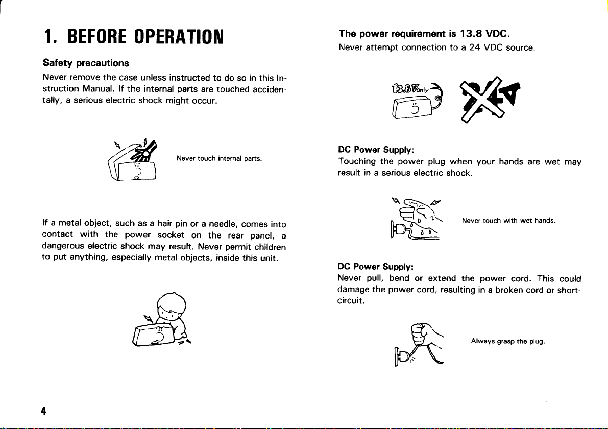
1. BEFORE
Safety
Never remove
struction Manual. lf
tally, a serious
precautions
the case unless
OPERATIOIII
the internal
electric shock
instructed
parts
are touched
might
occur.
to do so in
this ln-
acciden-
power
The
Never
requirement
attempt connect¡on to a 24 VDC
wls
is 13.8 VDC.
source.
lf a metal
contact
dangerous
to
put
anything,
with
object.
the
electric
such
as a hair
power
shock may
especially
Never
pin
socket
result.
metal
objects. inside
touch internal
or a needle.
on the rear
perm¡t
Never
oarts.
comes
panel,
ch¡ldren
this
unit.
into
DG Power
Touching the
result in
a
DC Power
Never
damage the
circuit.
Supply:
power plug
a serious electric shock.
b.-u
gqi.
when
Fhi-
Supply:
pull,
bend
or extend
power
cord, resulting
your
hands are wet
Never touch with wet
power
the
in
Always
cord.
a broken cord
grasp
the
hands.
This
plug.
could
or short-
Page 4
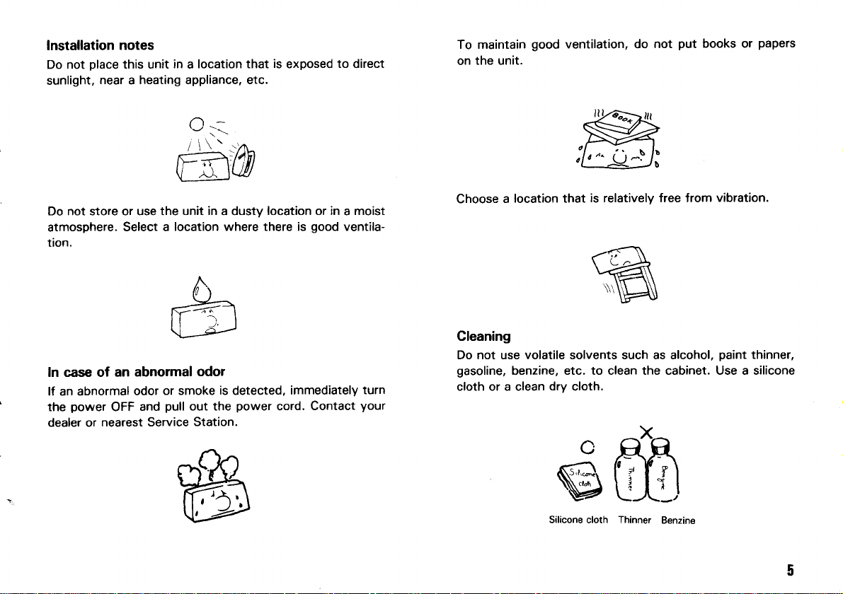
Installation
Do not
sunlight,
place
near a heating appliance, etc.
notes
this unit
in a location that
¡s
exposed
to
direct
To maintain
the unit.
on
good
ventilation, do
not
put
books or
papers
Do not store or use the
atmosphere.
tion.
ln case of an
lf an abnormal
power
the
dealer or
Select a
abnormal
or smoke
odor
pull
and
OFF
nearest Service Station.
unit in
a dusty
location where there is
odol
is
out the
location or in a moist
detected,
power
immediately
cord.
good
ventila-
Contact
turn
your
location that
Choose
Cleaning
Do not use volatile solvents such as alcohol,
gasoline,
cloth or a clean
a
benzine, etc. to clean the cabinet. Use a silicone
is relativelv free from
dry
cloth.
c
M
Silicone cloth
Thinner
Benzine
vibration.
paint
thinner,
Page 5
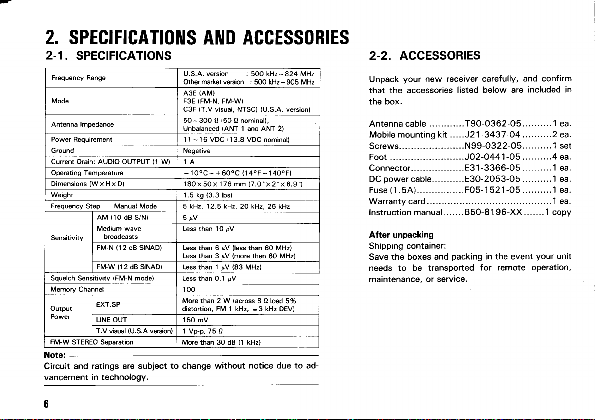
2.
SPEG|F|CAT|0ilS
2-1.
SPEC|F|CATTONS
Frequency Range
Mode
Antenna lmDedance
Power Reou¡rement
Ground Negative
Drain: AUDIO
Current
Operating Temperature
Dimensions
Weight
Frequency
Sensitivity
Squelch Sens¡tivity
Memorv
Output
Power
FM-W STEREO Separation
{WxHxD}
Step Manual Mode
Channel loo
OUTPUT
(1O
AM
Medium-wave
broadcasts
(12
FM.N
FM-W 112 dB SINAD}
{FM-N
EXT.SP
LINE
OUT 150 mV
T.V visual
(1
W) 1A
dB S/N)
dB SINAD) Less
mode)
(U.S.A
version)
AilD ACCESSoRTES
U.S.A. vers¡on :
market version :
Other
(AM)
A3E
(FM-N,
F3E
(T.V
C3F
50-3OOO(5OOnominal).
Unbalanced
l1 - l6 VDC
-
lOoC-
lSOx50x 176 mm
1.5 ks
kHz, 12.5 kHz,
5
5rV
Less than 10
than 6
Less than 3
Less than 1
Less than 0.1
More
than 2 W
distort¡on, FM 1 kHz,
1 Vp-p,75 O
More than 3O dB 11 kHz)
Note:
Circuit and
vancement
ratings are subject
in
technology.
to
change
FM-W)
visual, NTSC)
(ANT
(13.8
+600C
(3.3
lbs)
pV
(less
pV
(more
pV
(83
¡V
pV
(across
without
500 kHz-824 MHz
5OO kHz - 905 MHz
(U.S.A.
versionl
1 and ANT 2)
VDC nom¡nal)
(
l40F- l40oF)
(7.O'x2"x6.9"1
20 kHz, 25 k{z
than 60 MHz)
than
MHz)
60
MHz)
8 O load
+3 kHz DEV)
not¡ce
5%
due
to ad-
ACCESSORIES
2-2.
Unpack
your
receiver carefully,
new
that the accessories
listed
below are
and conf¡rm
included in
the box.
Antenna cable
mounting kit .....J2 1
Mobile
Screws......................
Foot .........................JO2-O441
Connector..................
power
DC
Fuse ( 1 . 5A)................FOs-1
Warranty card
Instruction manual.......850-81 96-XX.......1
............T90-O362-O5 .......... 1 ea.
-3437 -O4
..........2 ea.
N99-O322-O5.......... 1 set
-O5..........4
-3366-05
E3 1
cable...........E3O-2053-O5
52 1
.......... 1 ea.
.......... 1
-O5
.......... 1
............ ............ 1 ea.
copy
After unpacking
Shipping container:
Save the
boxes and
needs to be
maintenance.
or service.
packing
transported
¡n the event
for remote operation,
your
ea.
ea.
ea.
unit
Page 6
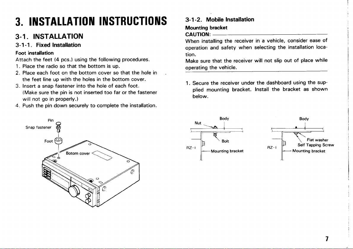
ilrtsTAltATlotl|
3.
INSTALLATION
3.1.
3-1-1.
Foot installation
Attach
1. Place the
2.
3. Insert a snap
4.
Fixed Installation
(4
feet
the
Place each foot on the bottom cover so
feet line up with the holes
the
(Make
sure the
will not
Push the
go
pcs.)
using the following
radio
pin
that the bottom is up.
so
fastener into the hole of each
pin
is not inserted too far or the fastener
properly.)
in
down securely to complete
lll|sTRucTl0tl|s
in
procedures.
that the hole in
the bottom cover.
foot.
the installat¡on.
3-1-2.
Mounting
GAUTION:
When
operation
tion.
Make sure
operating
1.
Mobile
installing the
Secure
plied
mounting
below.
bracket
safety
and
that the
vehicle.
the
receiver
the
lnstallation
receiver
when selecting
receiver
under
bracket.
vehicle, consider
in a
installation
the
will not slip out
the dashboard
Install the bracket
of
using
ease
loca-
place
while
the sup-
as shown
of
Snap
fastener
Pin
Body
Page 7
3-2.
3-2-1.
Before
1.
tor,
receiver,
Observe
2.
on
be
Notes:
Before
1.
negative
Afier
2.
correct
lead
lf the
3.
damage.
After-you
there
same
After
4.
tape
Do
5.
long.
CONNECTIONS
Precautions
disconnecting
connecting
sure
be
13.8
correct.
Red
Black
installing
installation
the
to
fuse
is
rat¡ng.
completing
to
not
engine
the
VDC,
The
lead
installation
have
no
Protect
remove
or
turn
to
key,
polarity
negative
power cable
(Positive)
+
-
(Negative)
the
from
and
battery
opens,
checked
problem
the
aga¡nst
the
and
of
power cable,
the
wiring,
before
terminal'
be
replace
fuse
the
off
the
cable'
the
ground'
is color
Polarity
battery
reconnecting
to
sure
the
wiring,
moisture'
even
power connec-
the
power switches
power supply'
DC
receiver
The
Battery
PolaritY
be
safety'
for
sure
be
check
cable
FUSE
the
wrap
if the
polarity
coded:
to
sure
double
to
each
determined
and
with
fuse
the
power
conductor
operates
remove
check
negative
the
one
holder
cable
of
the
muit
the
that
of
with
is
for
for
the
too
(A)
Antenna
¡nstallation
The
important
is
amateur
o,
"u",
provide
Á
possible,
results.
the
simple
Antenna
of
for
best
method
must
it
antenna
the
optimum
signals'
radio
results.
install
is to
extended
be
and
reception
good outdoor
A
wire
the
its
to
good earth
a
short-wave'
of
antenna
length
full
grounding
broad-
antenna
high
as
good
for
will
as
Page 8
U.S.A.
w¡th DC
power
version
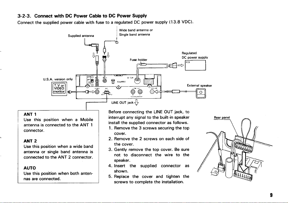
3-2-3. Connect
Connect the supplied
Power
cable with
Supplied antenna
only
DC Power Supply
to
Cable
fuse to a regulated
Wide
I
Single
I
",""0t
fi
+@d
power
DC
band antenna
band antenna
Fus€ holder
@@
supply
or
(13.8
-+l
VDC)'
Regulated
power
DC
r--l
External
supply
I
I
sDeaker
ANT 1
Use
this
when a
position
antenna is connected to the
connector.
2
ANT
position
this
Use
antenna or
connected
when a wide band
single band antenna is
to the ANT 2 connector.
AUTO
position
this
Use
nas
are connected.
when both anten-
Mobile
ANT 1
LINE OUT
Before connecting the LINE OUT
¡nterrupt
install the supplied connector as
1. Remove the 3 screws securing the
jack
signal to the built-¡n speaker
any
jack,
follows.
top
to
cover.
2. Remove the 2 screws on each
side of
the cover.
3.
remove the top cover. Be sure
Gently
not
to disconnect the
wire to the
speaker.
4. Insert the supplied connector as
shown.
5. Replace
screws
the cover and
to complete the installation.
tighten the
Page 9
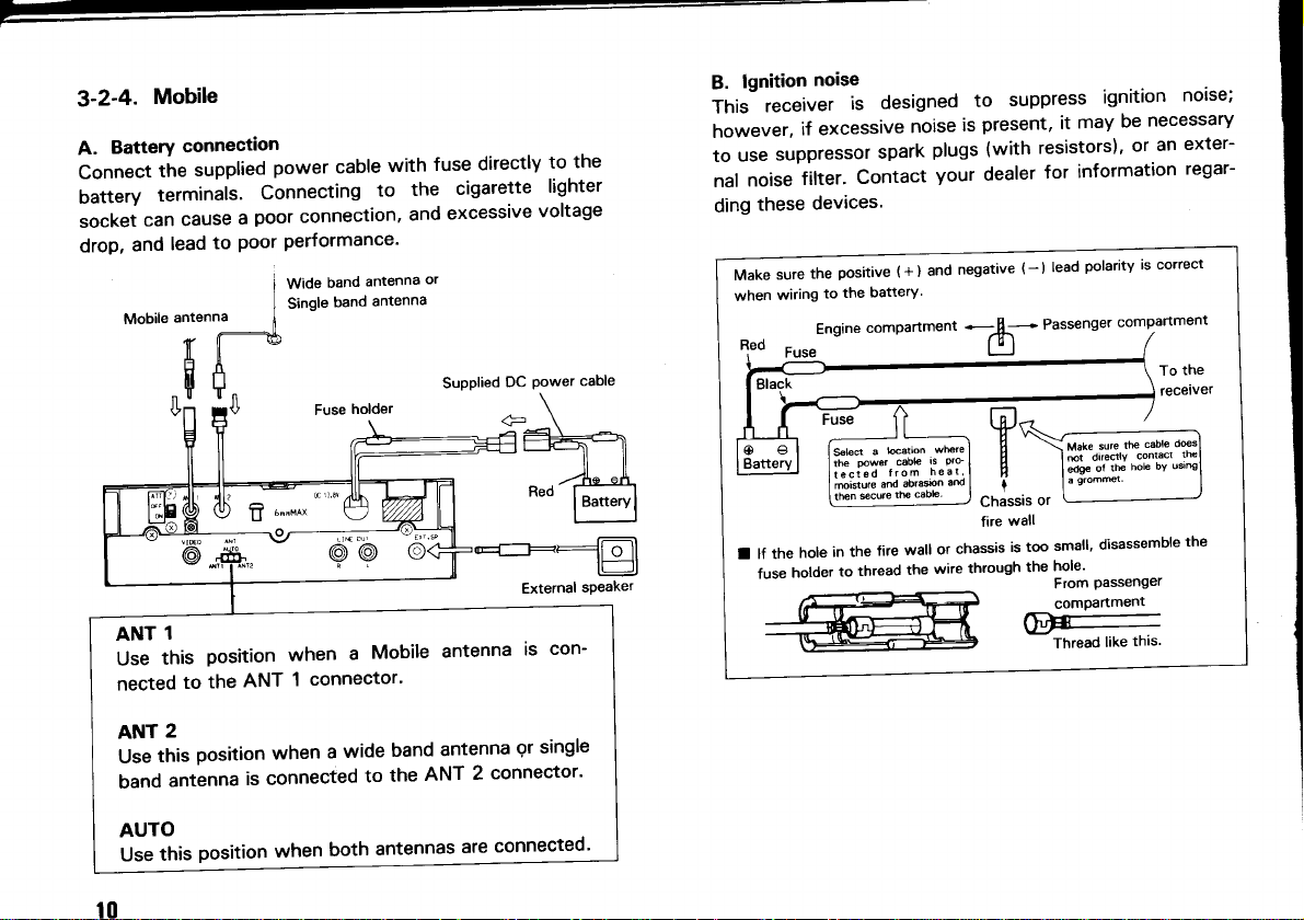
3-2-4.
A.
Connect
Uattery
Mobile
BatterY
tñe
terminals'
connect¡on
supplied
Connecting
power cable
w¡th
to
fuse
the
directly
cigarette
the
to
lighter
socketcancauseapoorconnection,andexcessivevoltage
drop,
and
Mobile
antenna
f ll
tfñ
["
"[|
Performance'
Poor
Wide
i
Single
I
i
*
band
band
antenna
antenna
or
Supplied
DC
Power
cable
to
lead
@@
1
ANT
this
Use
nected
position
the
to
ANT
when
connector'
1
Mobile
a
antenna
is
con-
lgnition
B.
Thishowever,ifexcessivenoiseispresent'¡tmaybenecessary
use
to
noise
nal
ding
Make
when
l"d
noise
receiver
suppressor
filter'
devices.
these
the
sure
to
wiring
Engine
Fuse
designed
is
spark
Contact
pos¡tive
battery'
the
compartment
(
+ ) and
suppress
to
(with
dealer
-
(
resistors)'
for
)
plugs
your
negative
-afu_- Passenger
LlJ
ignition
information
polarity
lead
compartmenl
or an
correcl
¡s
I
To
feceiver
noise;
exter-
regar-
the
w
v
n
t
or
Chass¡s
wall
I
lf the
fuse
hole
holder
in the
to
fire
thread
wall
the
or
wire
fire
chassis
through
small'
is too
hole'
the
From Passengel
compartment
F
Thread
d¡sassemble
like
the
thls.
t0
ANT
this
Use
band
AUTO
Úse
2
position
antenna
position
ttr¡s
wide
a
when
is connected
both
when
band
ANT
the
to
antennas
antenna
connector'
2
connected'
are
9r
single
Page 10
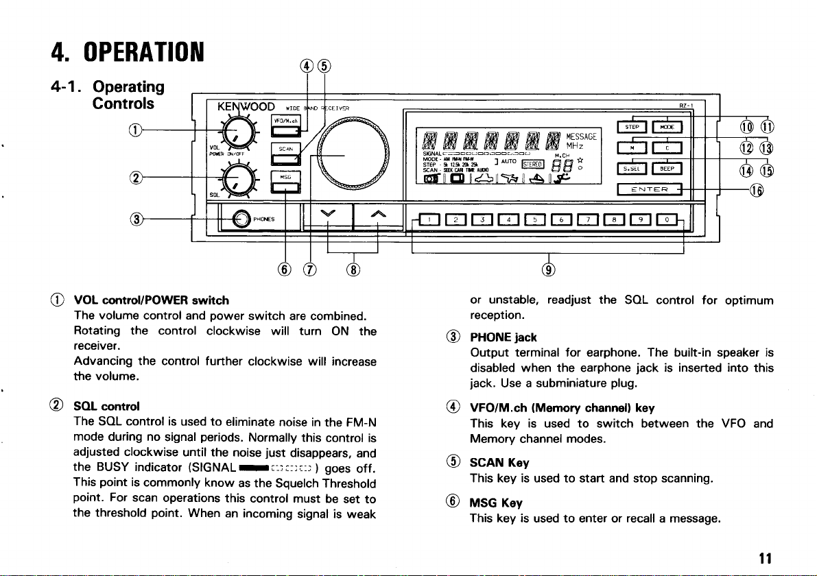
4. OPERATIOil
4-1.
Operating
Controls
EEEEIEEIEE
VOL control/POWER
e
The volume
Rotating
receiver.
Advancing
the volume.
SOL control
@
The
mode
adjusted
the BUSY
This
point.
the
the control
SOL control is
during no
clockwise
indicator
point
is
For
scan
threshold
sw¡tch
control and
the control further
signal
commonly
operat¡ons
point.
power
clockwise will turn
used to
until the
eliminate
periods.
(SIGNALrr-r¡-ri-r
When
noise
know
as the
this
an incoming
switch
are combined.
ON the
clockwise will increase
noise in
Normally
just
Squelch Threshold
control must
the FM-N
this
control is
disappears,
goes
)
be
set to
signal is
weak
and
off.
or unstable,
reception.
PHONE
@
Output
disabled when the earphone
jack.
Use a subminiature
VFO/M.ch
@
This key is used to switch between the VFO
Memory
SGAN Key
@
This key is used to start and stop scanning.
MSG Key
@
This key is
readjust
jack
terminal for earphone. The built-in speaker is
(Memory
channel
used to enter or recall a message.
the
channell
modes.
SOL control for
jack
is inserted into
plug.
key
optimum
this
and
ll
Page 11
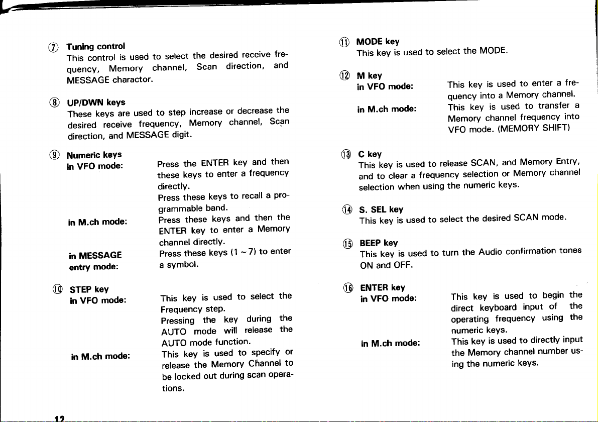
Tuning
o
This
quency,
MESSAGE
UP/DWN
@
These
desired
direction,
Numer¡c
@
in
in
in
entry
contro¡
control
Memory
charactor'
keYs
keys
receive
and
keys
mode:
VFO
mode:
M.ch
MESSAGE
moder
to select
used
is
channel.
used
are
frequency,
MESSAGE
the
Scan
increase
step
to
Memory
digit.
the
Press
keYS
these
directly.
these
Press
grammable
these
Press
ENTER
channel
Press
a
keY
directlY.
these
symbol.
desired
direction'
or
channel'
ENTER
enter
to
keYs
band.
keYs
enter
to
keYs
receive
decrease
and
key
frequencY
a
recall
to
then
and
MemorY
a
-
(1
to
7)
fre-
and
the
Scan
then
a
Pro-
enter
the
O
@
@
@
@
rey
t'looe
keY
This
rey
rt¡
VFO
in
M.ch
in
key
C
iey
This
to
and
selection
SEL
S.
key
This
key
BEEP
key
This
and
ON
used
is
mode:
mode:
used
is
clear
when
keY
used
is
is used
OFF.
select
to
release
to
frequency
a
us¡ng
select
to
turn
to
MODE'
the
is
key
This
quency into
is
key
This
Memory
VFO
the
channel
mode.
SCAN,
selection
numeric
desired
the
Audio
the
enter
to
used
MemorY
a
transfer
to
used
frequency
(MEMORY
Memory
and
Memory
or
keys'
SCAN
confirmation
fre-
a
channel'
into
SHIFT)
Entry'
channel
mode'
tones
a
@
sree
VFO
in
M.ch
in
r"v
mode:
mode:
key
This
Frequency
Pressing
AUTO
AUTO
This
release
be
tions.
mode
mode
key
the
locked
used
is
step.
the
function.
used
is
Memory
dur¡ng
out
keY
will
select
to
during
release
sPecifY
to
Channel
scan
the
the
the
or
to
opera-
@
VFO
M.ch
tey
mode:
eruren
in
in
mode:
keY
This
keYboard
direct
operating
numeric
This
the
ing the
keys'
keY
Memory
numeric
used
is
inPut
frequencY
to
is used
channel
keYs.
beg¡n
to
of
using
directlY
number
the
the
the
inPut
us-
Page 12

LGD display
Frequency display
@
slctal
@
?--:rrrrr¡rrr
BUSy
¡nd¡cator
MODE
srEP - 5k r2.5k
SCAN - SEEI(
6É-lE
Displays the
Memory Message.
This level
I
I
I
input
On
the FM-N mode.
ñirl tlul
,AI 'A(.'AI
-IIIII-IIIIII
-
AIII IM.I{
FM.W
zok zsk
CARI TITE
AUOIO
t¿>t
receive frequency,
meter indicates the relative
signal strength.
whenever
the squelch is
h-ul ,-\ul
'AI
nuro
]
\ñ
and
open
STEBEO
tJ\\lF
in
MESSAGE
@
On after
MSG key and when a
message is
MHz
O
On whenever a receive
frequency is displayed.
pressing
the
displayed.
@
$g="rt: #,igil,[f-%*
Displays the
quency
-
scan
@
O
lsTEREol
sEEr(
cABr Tr¡rE AuDro
Displays the
condition.
the scan function has
ON
casts.
STEP.
when
ruro
]
selected
selected Scan-Resume
Blinks
recieving FM
MODE
and Fre-
ON and OFF when
been selected.
radio
broad-
Symbol:
@
Blinks ON and OFF during Memory Entry.
t3
Page 13

REAR
nff
@
Aruf
@
anr
@
DC
@
connectof
VIDEO
o
panel
switch
I connector
2 connector
power
(U.S.A.
connector
version)
level
signal
The
nector
switch
signal
should
distortion
sw¡tch
weak.
This
to a
receiving.
This connector
to
single
This
the
This
television
is attenuated
is activated.
very
is
attenuated
be
of
when
OFF
connector
suitable
a suitable
antenna.
band
connector
VDC
13.8
connector
monitor
the
multi-band
from
strong,
signal.
the
should
mobile
should
used
is
Power
is used
to
1 con-
ANT
when
When
the
to
Prevent
Turn
is
signal
attached
be
antenna
attached
be
antenna
to connect
suPPlY.
connect
to
receive
this
the
signal
the
verY
for
or
T'V.
VIDEO
connect
to
broadcasts,
tape
switch
nruf
@
our
LINE
@
connectols
a
@
exr.
sP
iack
This switch
propriate
ANT
or
AUTO
In
automatically
ANT
ANT
These
tach
connector
amplifire
casts.
This
ternal
or
recorder.
is
antenna,
2.
Pos¡t¡on.
AM
1:
FM
OTHERS
2:
connectors
AUX
the
of
to
jack
for connection
is
sPeaker.
used
selected
500<frequency<
5
87.
connector
a STEREO
receive
a
select
to
1'
ANT
antenna
the
follows:
as
1 630
<
frequencY
1O8.1
used
are
stereo
ap-
the
AUTO
¡s
kHz
<
MHz
at-
to
TUNE
or
receiver/
broad-
an ex-
of
t4
Page 14

4-2.
The Receiver
tion is
4-2-1.
1.
RECEIVER
activated.
Reception
Connect the
set the
switches
POWER
POWER
SOL control
(VOL)
switch
POWER
OPERATION
will supply
power
supply
and controls
control :
of the DC
(VOL)
control
audio
confirmation
and the
as
(Fully
OFF
power
:
OFF
: Fully
counterclockwise
when
antennas,
follows:
counterclockwise)
supply(Fixed
and
Station)
a func-
then
4. Rotate
Then turn
disappears
-!::::ri:i
5.
Select the
the BUSY indicator
6. To
switch before
vehicle,
4-2-2.
Frequency
frequencies
Memory
the Tuning
the
desired frequency
turn off the receiver,
before
Frequency
can be changed in
can be stored in
page
Entry
control
SOL control
and the BUSY
goes
OFF
)
will
you
turn
you
stop
Selection
19.)
and
(Threshold
turn
ON and
turn
off the
the engine.
the VFO
the Memory
select
an open channel.
clockwise
indicator
point).
when
a
signal
S-meter will
off the
receiver's
power
mode. The
until
the noise
(SIGNAL
(FM-N
only)
is
received.
deflect.
POWER
supply, or if in
selected
channels.
(See
a
2.
Turn
ON
receiver's power
the
display is
using
the VOL
panel
and key's
the
display
control's
Note:
lf
sor
3. Turn
heard.
the
DC
switch
will indicate
not
as
procedure
control
EIE¡T=IEElElEIEE@
power
lights
supply
ON. After
as
shown
will
turn
shown Fig.
in
Sectk¡n
clockwise
and then
a few
in
on.
1
reset
¿l-3-2
until
a signal
Fig. I
the
page
turn
the
second
microproces-
1g
the
and
some
-
19.
or noise
is
A. VFO
To
rotate
the desired frequency
numeric
mode
select the
the Tuning
keys.
i.i
E=
desired operating
control,
E
E
frequency
press
the UP/DWN
directly
by using
EIE]EEEEIEE
in
the VFO mode
keys,
the ENTER
or enter
key and
t5
Page 15

Frequency
Direct
1. Press
SIGI{AL
toDESTEP
scAx
Enter the
2.
to enter
press
show:
SIGNAL
rooE-
STEP
scaÍ
Press
3.
selection.
SIG'{AL
TOD€
STEP
scall
EntrY
to the
of
-l
,-
to
LCD display
nearest
145.220
LCD display
.
complete
will show:
,-l
,-t
l_1. l-l l{thz
ENTER
the
-
5¡
-
sftÍ
rrttl
tttrl
key. The
..MHz
ftw
frequency
frequencV
the
2, 2. The
4, 5,
1
,
Itlt-
| |
-
5¡
-
srrx
rrtll
lllll
the ENTER
The
I
tJ
I
I
-
-
5T
-
srx
-f
-l.t-
rr'w
key
LCD display
t-_ _:r :!
t_ ,_
_1.
FFW
ltrll
will show
kHz. For
you
MHz
would then
MHz
Frequency
the
example
would
B. M.ch
The desired
same
Memory
the
Rotate the
enter
the
o
mode
Memory
controls
Channel,
Memory Channel
Tuning
frequency
a
ENTER
Direct
1. Press
key.
Memory Channel
the VFO/M.ch
SlGilAL
-
rODE
-
STEP
-
scAt{
lf M.ch OO
quency
2. Press the
Memory
the
keys.
5
LCD display
The
Channel
described
press
f¡rst
mode.
control,
directly
sErÍ
I
I
had been
will appear
desired
numeric key.
channel
will show:
can be
the VFO mode.
in
the
press
by using the
selected
VFO/M.ch
key to select
the UP/DWN
numeric
To select a
Recall
The LCD display
key.
previously programmed,
the disPlaY.
For example
35
you
would
press
the
using
or
keys.
keys and
will show:
fre-
the
to recall
then
3 and
The 1O kHz,
affected
by the current
t6
1kHz, and O.5 kHz
frequency step size.
frequency
digits
will be
Page 16

3.
Press
ENTER key to
the
nel recall. The LCD
SIGilAL
-
rooE
-
STEP
scal{ - sf¡(
tttl
(M.ch
35
had
display will
a
not been
complete the Memory
show:
MHz
.
t.cr
1\
I
previously
programmed.)
Chan-
European version
Frequency
Range
MODE AM
F. STEP
Symbol
ooo.s04
oo1.629
¡9kHz
,;
lo
a
3l
.630
001
I
087.495
AM FM.W FM.N
kHz
5
087.500
I
108.O50
kHz
50
,i
1 08.1 00
905.OOO
,
lo:l
I
VFO STEP
4-2-3.
MODE Selection
You must select
Each
key.
advance
(AUTO
mode cannot selected
you press
time
from AM to FM-N to FM-W to AUTO mode, etc.
mable band mode.)
AUTO mode
A.
selection
The AUTO mode
according
to the selected
U.S.A version
Frequency
Range
MODE
F.
STEP
Symbol
ooo.500
I
001.620
AM AM
I
1O kHz
lo
the appropriate mode using the MODE
the MODE key the receiver will
program-
the MODE
1 08.1
00
I
824.OOO
FM.N
2
VFO
STEP
function
:
:l
in M.ch mode, or
automatically select
frequency
oo1.630
{
087.495
5 kHz 1 OO kHz
as shown below.
087.500
(
108.OOO
FM-W
,;
lo:l
market
Other
Frequency
Range
MODE
F. STEP
Symbol
*r
The Frequency STEP size can be changed by using
following
1. Turn the
2. Press
key for 9
Turn
3.
*2
The VFO STEP
ooo.504
I
oo1.629
AM AM FM-W
r9kHz
6-
procedure.
POWER
hold the O key for lOkHz step, orthe 9
and
kHz
the POWER sw¡tch and then
ON
before the AUTO
oo1.630
I
087.495
5 kHz 1O0 kHz
switch OFF.
step.
will be the VFO
mode.
087.500
(
108.O00
,l
lO:l
release
that was selected
STEP
1 08.1 00
I
905.000
FM-N
,
VFO
STEP
the
the
key.
l7
Page 17

7-
MANUAL
B.
MANUAL
The
frequency
size
STEP
Frequency
The
in the
mode.
Each
from 5
lf
time
k to
mode select¡on
function
mode
and
MODE
selection
STEP
AUTO
press
you
1
the
2.5 k to
STEP.
can
size
mode, the
STEP
k to
2O
you
allows
be changed
mode
key the
25 k step.
receiver
set
to
in MANUAL
will be
will advance
the desired
released'
MEMORY
4-3.
4-3-1.
A lithium
memory.
power
The battery
the
the
Lithium
authorizéd
WOOD
CMOS
Microprocessor
Turning
cable,
battery
display.
battery
dealer,
type
battery
discharges,
KENWOOD
is contained
off the
power failure
a
or
should
last
replacement
the
or
circuitrY.
memory
POWER
for approximately
erroneous
an
service
factory,
back-up
in the
switch,
not erase
will
should
facility;
since
receiver
disconnecting
display
be
either
this
retain
to
memory'
the
years' When
ten
appear
may
performed by
your
KEN-
contains
un¡t
the
in
an
t8
4-3-2.
¡
lnitial
After
Microprocessor
the
of
state
tt ,-
,-r
t
-rrr
SlGl{AL
$i'iri.i[;I]il4l,huo,o'
@ l1.--l:ñ
6-l
second
few
a
,'l ,-l
L1
SIGI{AL
-
ltooE
-
STEP
-
srrf
scaN
I
I
In¡t¡al¡zat¡on
microprocessor
,-l
t-l
I
,
Af
t u
,/u
,-l
^'o
,-l
l'i¡Eo
1J\
t-l ,'l
tt-w
,-
t.-
251
l-l
l-t.l-l
tlll
factory'
the
from
7lm¡sslcr
lt
Í.cH
:
EE
s-'
|
t-l
tttnz
Page 18

.
Microprocessorlnitialization
you
When
display
itialize
want to erase all
should show erroneous
(reset)
the microprocessor using the
cedure.
There are
A. Rest
two methods
programmed
user
all
Memory
the
Turn the POWER switch OFF.
1.
Press
2.
Channels.
and
for resetting the microprocessor.
hold the
POWER switch.
3. Release the
B. Reset all user
the Memory Channels.
of
1. Turn the
2. Press and hold the
the POWER switch.
on
Release the M key and UP
3.
ENTER key.
programmed
POWER switch OFF.
M key
4-3-3. Memory Channel
This
receiver
provides
In addition to serving
memory channels are
the
10O
normal memory
as
used to specify other
The functions of these
below.
*
Memory Channel
OO are used to store
and
Band and Programmable
*
Memory Channel
10,20,30.
19,29,39,
09 are used to store
Band and Programmable
programmed
information,
data,
you
following
data except
ENTER
the contents of
key and
turn
data including the contents
(^)
and UP
(^)
Memory
Channels
key and turn
key.
(00-99).
channel
parameters.
Memory
Channels
40. 50, 60.
the limit for the
are discribed
70,
Programmable
Band Scan function.
49,
59, 69,
the limit for the
Band
Scan
function.
79, 89, 99,
Programmable
if
or
the
should
pro-
the
on
some of
80, 90,
in-
4-3-4. Memory Contents
Each Memory Channel
mode,
symbol
Message
4-3-5.
Memory Entry
1. Press the
Select the
UP/DWN
Select
(For
example
([l,
Memory
Memory
must be begun
VFO/M.ch key to select
desired
key, or the
the appropr¡ate
I
tJ t-_ _:l _:l
I
SIGIIAL
u*
$it8"-
-
srrx
scat{
is
@
page
25.)
Entry
frequency using the Tuning control,
numeric keys and the
145.220
|
t_ ,_ l_1.
_1.
t''*
ttttl
2. Press the M key.
previously
will
(For
recalled will appear and the channel
flash.
example M.ch O0 : empty)
SIGIIAL
-
TOOE
sf€P - 5r
-
$rf
scat{
lltl
The last
capable of storing
.....),
,
and message.
in
VFO mode.
the
the VFO mode.
MODE.
MHz, AUTO model
,-l
,-t
t_l
MHz
auro
I
Memory
'
-
--'J'-t
channel
.,
,THt
r-rr-l
l'|
the frequency,
(Refer
ENTER key.
that was
number
-
:
'
to
19
Page 19

3. Select
the desired
control, UP/DWN
(For
example
Press the 4 key, and
slc¡lL
-
Íoo€
sTEp - 5r
-
s¡¡¡
scat{
I
I
M key again.
4. Press
the
turn OFF.
t
I |
SIGI¡AL
!it&tscax
The receiver
tJ
'*
-
sttx
¡ttrl
Press the
5.
contents.
VFO/M.ch
Memory Channel
key, or the
M.ch 40;
.
I I
The
will return to
t-_ :l -:f
l_ ,_
_l .
t''t
I
key to confirm
using the
numeric keys.
then the O key.)
.
.MHz
\l/
-r
rt-l-
-'-i,
l'rt
I
Memory
channel
VFO mode.
t-t
,-t
l_1. l_l ?{thz
auro
the entered
-
|
number will
Tuning
Memory
4-3-6. Memory Recall
Please refer to
"Frequency
16.
4-3-7. Programmable
The Programmable Band
frequency
range. The range
in Memory Channel-O and
The corresponding
recall
mable Band
frequency in Memory Channel-O.
the
indicator is the * without the
Band
function
-9
numeric key
number.
Kev Memory Channel Key
1
J 30 39 8
4 40
5
example
For
Press the
1.
Select
(For
example
10 19 6 60
20 29
49
qn
VFO/M.ch
lower
the
59
key to select
frequency, and
145.220
Selection
allows
B. M.ch mode"
you
to define the
page
is determined by the frequency
follows.
as
be used to directly
can
program-
The
Memory
7 70 79
9
Channel
Memory Channel
69
80 89
90 99
oo o9
VFO mode.
the
MODE.
AUTO mode)
MHz,
the desired
20
I
LJ L--
|
S|GNAL
toD€-
- t-l ,-t
srEp
-
srrx
scAx
|
Ír-r
_(.
:J :J
t_
,-t ,-t
l-1. l-l ?{t}l¿
,_
ltlll
I t I t-
-i
t
r.cf
-l
,-1
SIGI{AL
Sroro"t- ,*
-
scaN
t''t
srrÍ
-l -l
f: f: t-t. t-t ?¡Hz
-.
^wo
I
t-l
t-l
ttltt
Page 20

2.Press
Select
ample
3. Press
return to the
Select
the M key.
the
-0
desired
low
end storage
M.ch 40)
-.
-l -f
t t
Itlt-
--l
|
SlGl{AL
ioD€- Ír¡
srEP-s¡
scAx-sttf
| | | | l'r.
the M key to enter
VFO mode.
the upper
frequency.
the data.
(For
r-lr-l
t-1. t-l
¡ | /
\"-./
-r-lll¿
example
location.
(For
t¡Hz
ít-l
u
The receiver will
146.0OO MHz)
ex-
Press the M key to enter
5.
VFO mode.
the
6.
Press
the
4 key. The frequency
the
LCD
display.
I
(
SIGi{AL
roD€- fx,r
STEP - 5T
scAr - str(
tJ t--
I
_l.t_
The radio will
ttttl
the
_:f _:l
,_ ,_l.t_l
The receiver return
data.
M.ch 40
of
the VFO mode.
select
,-t ,-t
will appear
to
in
I
I I
SIG}'AL
!rto"t-,,
scAt{
Press the M key.
4.
Select the
responds
(For
example
SIG¡IAL
fÍoDEsrEP
scAl{-st€x
tJ t-_
t"
-
srrx
,-t
t_l.
,-l ,-l
r_l tJ l_1.l_l MHz
^uro
I
,-l
ttttl
-9
desired high end storage
to the selected
lower limit.
M.ch 491
.
-
5r | | I I t/ |
ttttl
.
\
u
location
.ilH¿
I
\
-./
.
'-l
'-t
1-t,
/
\
-
that cor-
7. Rotate the
range.
Press
8.
the
Band function.
Note:
*
lf
either storage
key cannot
*
The AUTO
Tuning control
ENTER key twice
location
recall the
mode
cannot
has no
Programmable Band.
be selected.
to
confirm
to release the
contents,
frequency
the
Programmable
the numeric
21
Page 21

4-3-8. Memory
This feature transfers the memory
VFO. This
changing the contents fo the memory
1. Press
the
2. Select the desired Memory
Tuning control, the
and the ENTER key.
stct{aL
ÍooEsfEP
scAt{-srff
Shift
will allow
VFO/M.ch
you
key to
UP/DWN keys,
(For
I
tJ t-- _:l _:f
I I
-
5r
_(.
Fr-t
t_ ,_ l_1.
channel data
to
alter the
frequency
channel.
select the
Channel
M.ch
number
the numeric
or
example M.ch 40)
,-l
,-t
t_l
f.ci
,-,
1r-l
mode.
using
?tHz
,-l
ltttl
Press the M key. The data will be transfered to the VFO
3.
mode.
Rotate
the
Tuning
control to select the desired
frequen-
cy.
I
LJ L-_ :_t L_t
(
I
SIGI¡AL
toDESTEP
scAt{ - $tr
-1.
Ír-¡
-
¡T
t-
|
'-t '-t
l-l
t-1.
tlHz
tltll
to the
without
the
keys
4-4. SCAN
Scan is used to sample the band activity automatically.
4-4-1. SCAN Option
1. ALL BAND
Scan
2. PROGRAMMABLE BAND SCAN
The Scan frequency range is determined by the Programmable
MEMORY
3.
Scan
tually
mode)
4. MEMORY
The 10O Memory
groups
The
group.
you
lf
select the FM-N mode
just
the
to
operate
4-4-2. Hold/Resume Gondition
The receiver will
1.
SEEK Operated Scan
Scan will not
again.
2. CARRIER Operated Scan
Scan
resume if
SCAN
proceeds
over the entire band.
band function.
CHANNEL SCAN
proceeds
have
data and
those Memory
thru
CHANNEL GROUP SCAN
to 19, 20 to 29, ....90
{1O
proceed
Scan
(M.ch
SOL control
thru the selected
mode)
to the threshold
properly.
stop on a
resume
will hold as
the
long
signal drops out.
(VFO
mode)
(VFO
mode)
Channels that ac-
have not been locked
out.
(M.ch
Channels are devided into 10
to 99, 0O to O9}.
Memory
(include
busy
the AUTO mode),
point,
in
channel.
until the SCAN key
as the signal
order
is
present,
is
channel
for
pressed
ad-
scan
and
22
Page 22

TIME
3
4. AUDIO
4-4-3.
1. Press
Operated Scan
Scan will resume
stopping
even
if
the station is
Operated Scan
During
the FM-N mode
will resume
and
if
even
the station is
During the AM
Time
as
Operated
All Band
VFO/M.ch
the
approximately
and FM-W mode
Scan
key to
approximately
Scan will
present.
still
Scan.
select the VFO mode.
2. Press the S. SEL key to select
Press
3.
4.
the SCAN key to initiate
mode indicator will flash
reminder that
I
,
SIGX L
IODE- fr-r
-
sfEP
5r
-
scAt{
Press the SCAN key
the
t I t-
-', --r.
'Írf
'l''l
I
I
receiver
-l
f:
E
^uro
I
-
again or
-l
OFF
is scanning.
ing.
6 seconds
present.
still
stop by audio
6 seconds afterwards
the
scan is the
the Scan MODE.
SCAN. The selected
and ON as a visual
t-l t-l
t_t
\.
MHz
I
the C key to clear
after
signal
same
Scan
scann-
4-4-4. Programmable Band
1. The scan
following Memory
Kev
,|
2
?
4 40 49
2. Press the VFO/M.ch
3. Press the
4.
Press-the desired
(For
limit
Memory Channel
30 39
50 59 o
S. SEL
example
t
LJ
I
SIGNAL
MOOE- fr-r
STEP-5r
-
scAN
frequency
Channels.
10 19
20 29 7
key to select
key
to select the
recall
key
press
the 4 key.)
f_ _:l
l
_l.t_
lrr
---l
,_
Jxuru
tttlt
Programmable
The Programmable
5. Press
6. Press
the
mode
indicator
reminder
the
SCAN key
that
SCAN key
ing.
7. Press
the ENTER
mode.
Band indicator
to initiate
will
flash
the receiver
again
key
twice
Scan
pairs
must be stored in
Key Memory
6
n
9
Channel
60 69
70 79
80
90 99
oo o9
VFO
the
mode.
Scan mode.
using the numeric keypad.
,-t ,-t
t_l.l_l
Band indicator
will light.
SCAN. The
OFF
is
scanning.
or the
to return
and
C key
selected
ON as
to clear
to normal
a visual
scann-
the
89
Scan
VFO
23
Page 23

Note:
lf either channel
the Programmable
recall
to
4-4-5.'
1. Press
2.
3.
Memory Channel
the VFO/M.ch
Press S. SEL
Press the SCAN
mode indicator
reminder
4. Press
that
the SCAN
ing.
4-4-6.
1. Press the
2.
3.
Memory ChannelGroup
VFO/M.ch
Press the S.SEL
Press the desired
keypad.
number
Sroup
1
3 30-39
4
5
Memorv Channel GrouD
10-19
20-29
40-49
50-59
¡s
empty,
the
band.
Scan
to select the
key
key to select
initiate
key to
flash OFF and ON
will
the receiver
key again or
key to select the
key to select
group
number key
numeric keys
the Scan
is
scanning.
mode.
The selected Scan
SCAN.
the C key
Scan
the Scan
using the
numbe¡
o
7
8
I
0
will not be able
M.ch mode.
as a
to clear scann-
mode.
M.ch
mode.
numeric
Memorv Channel
60-69
70-79
80-89
90-99
o0-09
visual
4. Press the SCAN
indicator will
mode
reminder that
Press the
5.
key to
the receiver
key
SCAN
ing.
DIRECTION
SCAN
will begin
Scan
the direction
counterclockwise.
4-4-7.
Memory Channel
The Memory
porarily
in an upwards direction.
by
or
Channel
unwanted
skip
Memory Channel Scan
1. Press the
2. Select the
ing the MAIN
Press the STEP key.
3.
A
star
number. This
ped
VFO/M.ch
(*
)
during
I t I t-
t
SIGNAL
3P.T:
-
scaN
Memory
Tuning control.
will appear
indicates the
Memory
-i
ü.
Fr-i
lrmt
tllll
initiate
SCAN.
flash OFF and
is
scanning.
or the C
again
The
selected
ON as a
key to clear scann-
You can reverse
Tuning control
rotating
pressing
by
the
the
UP/DWN
Lockout
Lockout function allows
Memory Channels
mode.
key to select the
Channel that
left of the
to the
M.ch
you
wish
Memory Channel
to skip by us-
Memory Channel
Channel Scan operations.
t-l ,-l ,-l
t-t ,-t t-1.
,-l
t-l MHz
Í.ct
,-!
4
*
keys.
you
to tem-
during
mode.
be skip-
will
scan
visual
the
24
I
Page 24

4. Repeat
Channels
steps 2 and 3
that
5. To cancel
nel as discribed
The star
(*)
be scanned
Note:
you
lf
enter new data
the
lock
out
will
you
lockout,
the
in steps
go
w¡ll
normally
be released.
to lock out any
want to skip.
the desired
select
1, 2,
and 3 above.
The Memory
out.
into a locked
out
other Memory
Memory
Channel
Memory
will now
Channel,
Chan-
4-5. MESSAGE MEMORY
Memory channel can store a seven
Each
message, in addition to
tents.
4-5-1.
Message
Message Entry
must be
Entry
1. Press the VFO/M.ch
the desired
Select
key. or numeric
DWN
Select the
(For
appropriate
example
145.22O
the normal memory channel con-
performed
key to select the
frequency using
keys and
MODE.
MHz, AUTO mode)
in
VFO mode.
the
VFO mode.
Tuning control.
ENTER key.
characters
UP/
I
LJ L-_ _:f -:l
I I
SIG}{AL
$&o"tl ,*
-
stef
scAil
ttttl
Press the M key.
2.
will
appear and
(For
example
I
tJ t-_
(
SlGilaL
toDE- fÍ.i
-
5r
STEP
scaN-slr{
| | | | l'r'
t_1. t_l
auro
I
previous
t'-t
_1.
t_ ,_
The
the channel number
M.ch 49)
,-l ,-l
t_l.
|
r_l ,_l l_1.l_(
'-t '-t
Memory
,-l ,-l
,'.-.2
,
will
. | /
r_l ,_l
|
_f
MHz
flash.
MHz
.
Channel data
-
25
Page 25

7
3. Select
the Memory channel
you
want to
message on using the Tuning control, UP/DWN key,
numeric keys.
the
(For
example
M.ch 45; Press
key, and then the 5 key.)
SIGNAL
ilODEsrEP - rr scAN-s¡tf
| |
Press the
4.
The
message
Rotate
5.
as shown
ABCDE F GHI
YZ, " r'*u{1234
MSG key.
MESSAGE
cursor
--:tj,-
--
SIGt{AL
tooE- fr-r
-5*
STEP
-
sttx
scail
I
I
Tuning control
the
below.
..MHz
\
,
| /
\
,
,-l t-
|
-.
-l
| | i'1.-
light and
indicator
will
(
r--¡ : blank)
KL MNOP ORSTUVWX
J
will
flash
and OFF.
ON
to
select
56789-+/=B-
MESSAGE
¡ lt-
-t -t
the desired
-
the
enter a
or
4
the
leftmost
character
t
l /'
,, r
's,b*).
MOOE- fr-r
srEp - st
scaN-sErx
MESSAGE
,-l i=
|
-l
ttttl
Press
6.
key to
For
example select
(¡
the UP
return
key to
)
backward.
"KENWOOD"
,-/,--- A l, I
,-f
SIGNAL
rrooE- rr'i
srEP
SCAN-Sttx
-*
I
t/\t t I t_t¿-Ltl
v
I
go
ahead, and the DWN
r-l r-l--'il'ltrssnct
/
l\
t-l
tr
|
-l
(v
)
ttttl
7. You
the following symbols.
1234567
6@-f @
For example
press
may
L/
f_
r
,
,_ t
STGNAL
¡roDE- fr I
-5r
srEP
scAN-sErx
I l"'-}l
one of the
l*f
press
the 3 key.
^1, I r-l
\l
t/\t
1-7
numeric keys
\ñ
l!\ |
r-l-Tllrssncr
t_tz
\l
/ | \
| |
-!t
t-l
to
enter
s-
lreraset
:
E
t
_t
l
26
Page 26

8. Press the M key
.
will turn OFF. And the receiver
agan. The Memory
mode.
I
|
SIGXAL
SStl r,
-
sca¡
tJ ¿-_
(
ttt
sarr
-1.
:-_f
t_ t_
^uro
I
_:l
rtttl
Press
9.
the
VFO/M.ch
ILJ
t(
SIGXAL
TOD€- FI-I
-
STEP
-
stt¡
scaN
I
I
key
to confirm
L-_ :-t
_1.
t_
,_
:J
t4t
will return
,-t ,-l
l_1.
t-t
\. \
tl
Channel number
to the VFO
l_l
Jl.Hz
the
¡nformat¡on.
,-t
?{tHz
t.cñ
t lt-
-t -t
1 1. Press the VFO/M.ch
again.
4-5-2.
A.
Message
M.CH mode
1. Press
the
2. Rotate
Memory
SIGI{AL
toDE- tt'i
STEP
SCAN
Press
3.
the MSG key
Memory
VFO/M.ch
the Tuning
channel.
I
LJ
I
-
-
I
(For
L-_ _--f -:l
I
_l.l_
frrf
l"-)l
to
key
to return
Recall
key
to
select the M.ch mode.
control
to
select the desired
example M.ch 45)
,-t ,-l
t_
t_l.t_l
'-T
| |
display
the
message.
to the VFO
t
I
mode
A MESSAGE
a message has
1O.
Press
L/
,r
SIGI,¡AL
MOOESTEP
SCAN
Memory
been
the MSG key
Al,
L-_
\l
l_ t
füi
-
-
I
Tlrr
l"-)l
indicator
stored for
to review
I t-l
\l
t/
,_l
will light, to remind
that Memory
the
Message.
t-l
Tlmrssncr
l_l
_Ll
McN
'-!
.
\
| |
you
channel.
L/
L=
,\
l_ t\l t/\l
SIGNAL
MOO€SÍEP
scaN
fr'r
-
-
I
Rotate
the Tuning
Memory
Press
will
Press
key.
Scan
channel.
the
SCAN key,
display Messages,
the desired
the receiver
of the Message
^l
' l '-l
Írt
lr')l
control, to
the receiver
rather
numeric
will initiate
display.
'-l
,_l
7l
!
t_l
Ll
I
I
select
the desired
w¡ll ¡n¡tiate
than Frequency
key
and then
Memory
MESSAGE
CH
t
t-
:t.
press
Channel
Message
Scan and
data.
the SCAN
Group
2t
Page 27

VFO Mode
B.
Press the
1.
2. Rotate the
Press the MSG
3.
The receiver
channel that
display.
VFO/M.ch key to select
Tuning control
to select a desired
key.
will display
has the same
the Message
frequency
VFO mode.
the
of the Memory
that appears
frequency.
¡n
the
4. Press the
MSG key again
return to the
to
VFO mode.
l_ I
-
tr'r
^ | '
tt
Ítr
L/ L-_
r
,-
SIGNAL
!t"|"t:
scAN
ttttl
lf more than 2 Memory
quency
channel
lf
Memory
the
be as shown below.
SlcTAL
ilooE- fr-l
SÍEP
SCAN
The message display
¡n the associated
stored
empty).
ll^+^.
Symbol
ing this
28
VFO,
as the
will
be displayed.
channel
-
-
(
I
I
6-
nrt
,
@
operation.
tttl
| '-l t-l
t1
tl
I
25r
¡_,
auro
,_l
7f
_Ll
Channels have the
the message
has no
^uro
I
25t
of the
message, the
will not change if there
memory channel
d-J
.....) will
,
mrssnce
fre-
same
lower
memory
display
fi!ESSAGE
(i.e.
not change dur-
will
is no
data
channel
is
Page 28

MAITUTEIIIAII|CE
5.
5-1.
Your receiver has
specif
cumstances the receiver
these operating
coils
only be readjusted
equipment.
Attempting
t¡on can void the receiver's
When
years
mation
cedures which
test
5-2.
Should
to
original box
the
number. You
directly related
Caution:
Do not
ment. Extensive
GENERAL INFORMATION
been factory
ication
your
in
operated
of service
in
equ¡pment.
bef
ore shipment.
instructions.
receiver
service
this section
were
by a
or alignment
properly,
without requiring
can
be accomplished
qualified
gives
SERVICE
it
ever become
your
dealer
problems
pack
or service
and
involved.
need
to
the equipment
necessary
packing,
not
the service
damage
may result
aligned
Under normal
will operate
All
adjustable
preset
at the factory
technician with
without
warranty.
the receiver
realignment.
general
some
without
to return
center for
and include
Also include
return
problem.
in
crushed
repair,
accessory items
newspapers
during shipment.
and tested
in
accordance
trimmers
factory
provide
will
service
sophisticated
the
pack
full
a
description
your
to
cir-
with
and
and
should
proper
test
authoriza-
many
The
infor-
pro-
equipment
it in
its
of
telephone
unless
for
ship-
Service note:
you
lf
desire to
problem,
point,
the
Please
list: Model
give
Please
as
other equipment in
anything
diagnosis
Notes:
1. Record
2. For
3.
should be included.
from
whom
your
maintenance
When
claiming
of sale, or
must
sale
correspond on
please
make
and PLEASE make
and
problem
The
sufficient
you
else
the Date
own information,
accompany
feel
of
purchased.
performed
warranty
proof
other
5-3. CLEANING
The knobs, front
to become soiled
removed
and
and a
from the
warm
damp cloth to
panel
after extended
water.
Use a neutral
receiver
clean
your
note
it readable.
Number
Serial
you
are having.
detail to
Purchase,
and cabinet
diagnose. Information
the stat¡on,
might be
retain
on the unit.
service, a
purchase
of
the radio.
and cleaned
soap
the
cabinet
a technical
short,
useful in
Serial Number
a wr¡tten record
of the receiver
use. The
or operational
complete,
meter readings
photocopy
showing the
knobs
with a neutral
(no
harsh
and front
and to
such
and
attempting
and Dealer
of any
of the bill
date of
are likely
should be
soap
chemicals)
panel.
29
Page 29

b'
lN
5-4.
¡
Heterodyne tones
.
The
ponents.
CASE of
problems
described
Examine and check
Symptom
Indicators do
is heard when the
noise
not light and no receiver
is turned ON.
Nothing is displayed or
are displayed
is turned
No signal
when the
ON.
is received.
No sound is heard.
Howling occurs
when using the ¡nter-
nal speaker.
DIFFICULTY
may occur happen in the
in
this table are
according
power
switch
incorrect
power
switch
digits
failures caused, in
to the
1. Bad
2. Blown
The microprocessor may malfunction
the input voltage
1. Bad
2.
3.
This may occur from raising
excessively
AIR band,
the HF band.
and
general,
This
improper operat¡on
by
following table.
Probable cause
power
cable or connections.
power
antenna
ANT switch
SOL
position.
control fully clockwise
fuse.
supply
is
low.
too
connections or
incorrect
in FM-N
mode.
Incorrect mode for the selected
quency.
the volume
poor
because of
reception.
is not
to defective components.
due
of the
1. Check cable
2. Be sure to check
has
cuiting, then
of the same
Adjust the supply
if
voltage
nominal).
1.
Check
switch.
2. Turn
wise.
fre-
Press the
3.
rect mode.
1. Reduce the
2. lf volume
ternal
receiver, not by defective
Corrective
not been damaged
rating.
action
and connections.
that each conductor
by shortc¡r
replace
with a new
voltage to
of 11-16VDC
antenna connection,
(13.8VDC
com-
fuse
provide
ANT
or
the SOL control counterclock-
MODE key to select
the cor-
volume when using.
ex-
is insufficient. use
and
speaker.
a
30
Page 30

6. SCHEMATIG
DIAGRAM
7.
0PTt0NAt
ACCESS0RTES
(another
sheet)
t SP-40
I SP-SOB
Compact
flexibility
I PG-2N
COMPACT
and smart,
of installation
DC POWER
MOBILE
high
MOBILE
SPEAKER
quality
for maximum
CABLE
SPEAKER
(8
external
(4
ohms)
ohms)
speaker
convenience.
provides
3l
Page 31

,
REFERENCE
8.
8-1.
8-1-1
Various
available.
antenna
ANTENNA
. Fixed
types
Receiver
antennas
band
Station
fixed
of
performance
fixed station
For
used.
(omnidirectional).
Coaxial
cable
---.dl
-lF
ffiH
7r
station
depends
antennas
o-r^,
I
l{
largely
operation
ptane
antenna
commercially
are
type of
the
on
there are
wide
8-1-2.
Various types
are available.
these
Note:
For
grounded
diagram.
na installation
Mobile
of
Please consult
antennas.
gutter-mount
the car
to
Attach
instructions
r-Tt¿D\\
v@F::rep¿
antennas
installation,
body as
the antenna
provided
Roof
top system
.,1------¡r
Front fender
Installation
for UHF/VHF
your
dealer
the antenna
shown
securely,
for mobile
mobile
for
in the
referring
with the
Roof
s¡de
Trunk lid
operation
bracket
operation
information
accompanying
to the anten-
antenna.
svstem
system
on
must be
32
Page 32

Pass
through the
rear window.
-1
,Ta"
Coaxial
;,=-
these
grounding
cable
L¡ft the trim
¡nstall the cable.
plate
pa¡nr
ove the
areas to insure
Pass
f¡tting. The
inserted eas¡lv if
cushion is soft. Note that
ra¡n water may enter
the cable.
from
to the
car body
through the door
cable can be
the door
and
along
Coax.
cable
routing
33
Page 33

8-2.
kHz
525
1 606
1 705
1 800
2000
2300
2500
3200
3400
3500
3800
3900
3950
4000
4750
5000
5060
9500
9900
1
0000
RADIO
2nd
Zone
:::"
FREOUENCY
3rd
Zone
ALLOCATION
MHZ
00
1 0.1
10.150
11.650
12.050
1 3.600
13.800
14.OOO
14.350
15.000
00
l 5.1
15.600
17.550
17.900
18.068
1
8.1 68
20.ooo
21.000
.450
21
21.850
24.890
24.990
25.000
25.670
00
26.1
28.OOO
29.700
]::"
2nd 3rd
Zone
Zone
MHz
50.ooo
54.OOO
68.OOO
72.OOO
76.OOO
B7.OOO
108.000
144.000
146.OOO
148.0O0
174.OOO
216.OOO
220.OOO
225.OOO
230.OOO
430.ooo
440.000
470.ooo
608.000
614.ooo
890.Ooo
902.OOO
905.000
1 st
Tone
2¡d
Zone
3rd
Zone
Zone:
1st
Europe
Mongolia
and
Zone:
2nd
South
Zone:
3rd
and
Asia
Mongolia
and
.
ln
tions
m
r
tl
Africa
and
included)
America
North
and
Oceania
excluded)
countries,
some
accord
not
do
Standard
Broadcastband
Amateur
stat¡ons
Other
(Soviet
(Soviet
frequencies
with
f requencY
time
band
Russia'
Russia'
table'
this
Turkey
Turkey
alloca-
Page 34

KENWOOD
 Loading...