

Page 1

.
© 2017
NX-5000 series
Common Function Reference
(Common FUNC)
Version: 2.20
Last Updated: June 30, 2017
Language: English
Type: K, F
Page 2

CONTENTS
CONTENTS
CONTENTS
About This Manual viii
How to Read the In-depth Manual ix
About Notations x
About the Notation of the Supported
Models x
About Examples of the Transceiver
Display x
Abbreviations Used in This Document xi
About Copyright xii
Software Copyrights xii
Firmware Copyrights xii
About Trademarks and Patent Rights xii
About the Programming Software xiii
About KPG-D1N xiii
About the Notation of “Configuration
Using KPG-D1/ D1N” xiii
About the Zone-channel Format xiii
About System Type xiv
About Multi RF Deck/ Multi Control Head xiv
About Options to Use the Functions Described in
This Document xv
About the Built-in GPS Receiver Unit xvi
How to Search for Information xvi
Outline of This Transceiver xviii
GENERAL FEATURES xviii
P25 DIGITAL MODES xix
NXDN DIGITAL MODES xix
DMR CONVENTIONAL MODES xx
ANALOG MODES xxi
Revision History xxii
CONTENTS BY PURPOSE xxviii
1 FUNCTIONS AND PANEL LAYOUT 1
1.1 NX-5200/ NX-5300/ NX-5400 1
1.2 NX-5700/ NX-5800/ NX-5900 3
1.3 About LCD 9
LCD 9
Icons 16
Key Guide 17
2 GETTING STARTED 20
2.1 Connecting the Transceiver to a PC 21
2.2 Connecting the Transceiver to a PC by
Bluetooth 22
2.3 Writing the Configuration Data to the
Transceiver 22
Writing configuration data to multiple
transceivers using Bluetooth
communication 23
About the writing of configuration data in
a Multi RF Deck/ Multi Control Head
structure 23
2.4 Reading the Configuration Data from the
Transceiver 23
2.5 Embedding a Message in the Transceiver
(Embedded Message) 24
Embedded Message 24
Embedded Message with Password 24
2.6 Writing Configuration Data Using Wireless
Communication (OTAP) 25
3 BASIC OPERATIONS 26
3.1 Turning the Transceiver ON/ OFF 26
Turning the Transceiver ON 26
Turning the Transceiver OFF 28
Power Switch Status Memory 28
3.2 Adjusting the Volume Level 29
3.3 Using Function Keys 29
Mode Reset Timer 30
Keypad Operation 33
Manual Dialing 36
3.4 Using Menu Mode 37
3.5 Changing the Zone-channel 40
Changing the Zone 40
Changing the Channel 41
Rollover/ End Stop 42
Changing the Channel by Specifying the
Number (Channel Entry) 42
Changing the Group ID by Specifying the
ID (Group ID Entry) (NXDN Trunking
System Only) 44
Changing the Channel with a Single
Touch 45
Home Channel 45
Direct Channel 46
Common FUNC (K, F)/Ver 2.20 i
CONTENTS INDEX
Page 3

CONTENTS
3.6 Transmitting/ Receiving 48
3.7 Viewing the Receive History (Stack) 49
Configuring the Display Order of Data in
Stack Mode (Stack Order) 54
Enabling the Storage of Redundant Data
(Repeated Calls Stack) 54
Displaying the Caller ID when Displaying
a Message (Caller ID for Message) 54
Displaying the Receive Channel
(Channel Name (Message Display)) 55
Stack Procedure of the Receive History
(Old Message Overwrite) 55
Caller ID Stack 56
Time Stamp 57
Message Memory 57
Clear Caller ID Stack on Reply 57
3.8 Operating the Transceiver in Each Mode
(Common Operation) 58
Selecting or Clearing Data from a List 58
Entering or Deleting a Code 61
Entering or Deleting Characters 63
Scroll Display 68
Character Entry 69
3.9 Locking the Transceiver Keys (Key Lock) 70
Auto Key Lock Timer 72
3.10 Operations in a Single RF Deck/ Dual
Control Head Structure 73
About the Behavior in Function Mode
While in a Dual Control Head Structure 74
About the Reception Display of a Short
Message When in a Dual Control Head
Structure 75
About Featured Panel Operations 75
3.11 Switching the Display Language 76
4 TRANSMISSION/ RECEPTION 77
4.1 Transmit/ Receive Frequencies 77
4.2 Transmit Power 77
4.3 Channel Spacing 80
4.4 Beat Shift 82
4.5 Displaying the Signal Strength Level (RSSI
Level, BER) (Maintenance Display) 83
5 INDICATION AND DISPLAY 88
5.1 Busy LED 88
5.2 Transmit LED 88
5.3 Selective Call Alert LED 89
5.4 Optional Signaling LED 90
5.5 Lighting the Backlight (Backlight) 91
5.6 Changing the Brightness of the Backlight
(LCD Brightness) 93
5.7 Changing the Color Scheme of the
Transceiver Display (Color Scheme) 94
5.8 Automatically Adjusting the Brightness
Level of the LCD (Auto Dimmer) 94
5.9 The Icons on the LCD 96
5.10 Displaying the Signal Strength (Signal
Strength Indicator) 99
5.11 Display Functions of the Display 100
Zone Name Display 100
Display Format 100
Power-on Text 101
Sub-LCD Display 102
Sub-LCD Display Priority 103
Clock Display 103
5.12 Customizing a Displayed Text String
(Display Customization) 103
5.13 Displaying a Bitmap Image When the
Transceiver is Turned ON (Custom Startup Screen) 104
6 SOUND 105
6.1 Tones that Sound When a User Operates
the Transceiver or When the Transceiver
Status Is Changed 105
Power-on Tone 107
Control Tone 107
Warning Tone 109
Locator Tone 111
Sidetone 112
Alert Tone 112
Volume Level Tone 113
Transmit Tone 113
Common FUNC (K, F)/Ver 2.20 ii
CONTENTS INDEX
Page 4

CONTENTS
6.2 Tones that Sound When the Transceiver
Receives a Call 114
Configuring the Alert Tone (Alert Tone
Pattern) 117
6.3 Tones that Sound When the
Communication Starts/ Ends 118
Using Sound to Notify the Timing to Start
Communications (PTT Proceed Tone) 118
Using Sound to Notify the Other Party
that the Communication Ends (PTT
Release Tone) 119
6.4 Functions Related to the Volume
Configuration 120
Configuring the Minimum Volume Level
(Minimum Volume) 120
Configuring the Maximum Volume Level
(Maximum Volume) 120
Configuring the Offset Value for Volume
Level (Tone Volume Offset) 121
Configuring the Volume Level of Various
Tones (Tone Volume) 121
Changing the Tone Volume Level with a
Single Touch (Selectable Tone Level) 122
Temporarily Reducing the Volume Level
of the Speaker (Speaker Attenuation) 122
6.5 Using the Transceiver as a Megaphone
(Public Address) 123
About the Speaker to Emit Audio 124
6.6 Restricting Alert Tone When Consecutively
Receiving a Call (Alert Tone Restriction
from 2nd Call) 125
6.7 Configuring Audio Profile (Audio Profile) 127
General 128
RX Audio Response 132
TX Digital Audio Response 134
Active Noise Reduction 136
6.8 Using Voice Guidance (Voice
Announcement) 138
Configuring Voice Guidance Method
(Voice Announcement Type) 138
Zone-Channel Guide 139
Function Guide 140
Status Guide 142
7 BATTERY 144
7.1 Displaying the Remaining Battery Power
Level (Battery Indicator) 144
7.2 Warning that the Battery Voltage Is Low
(Battery Warning) 145
7.3 Warning the Battery Power of the Vehicle
Battery Is Low (Battery Warning) 146
7.4 Displaying the Remaining Battery Power by
Operating the Transceiver (Battery Status) 146
7.5 Reducing Battery Consumption (Battery
Saver) 147
7.6 Displaying the Remaining Battery Power
When the Transceiver Is Turned ON
(Power-on Battery Information) 148
7.7 Checking the Detailed Information of a
Battery (Battery Information Display) 149
8 GPS POSITION DISPLAY 150
8.1 Configuring the GPS Position Display 150
8.2 Displaying the Location Information 151
9 STORING RECORDED AUDIO/ GPS
DATA 153
9.1 About microSD Card 153
Formatting a microSD Card 154
Removing the microSD Card 155
Folder Structure of a microSD Card 156
Configuring the Warning Behavior for the
Remaining Memory Capacity (Low
Memory Warning) 158
Configuring the Storage Method of an
Audio Data File (First-in First-out
Deletion) 159
9.2 Recording Received Audio Automatically
(Auto Recording) 160
Configuring Recording Time (Maximum
Recording Length) 163
9.3 Recording Audio to a microSD Card (Voice
Memo) 164
About the Audio to Be Recorded 165
9.4 Playing Back the Recorded Audio
(Playback) 166
Storing Audio Data in the Saved Folder 171
9.5 Storing the GPS Data (GPS Data Storage) 172
9.6 Confirming microSD Card Contents via a
PC (SD Card Direct Access) 173
Common FUNC (K, F)/Ver 2.20 iii
CONTENTS INDEX
Page 5

CONTENTS
10 BLUETOOTH COMMUNICATION 176
10.1 Toggling Bluetooth On/ Off 176
10.2 Finding a Bluetooth-compatible Device
(Bluetooth Find Device) 177
About the Displayed Contents of a
Bluetooth-compatible Device 179
Configuring the Bluetooth Device Name
of the Transceiver (Bluetooth Device
Name) 180
Checking the Bluetooth Device Name
(Bluetooth Information) 181
Responding to the Search of a Bluetoothcompatible Device (Bluetooth
Discoverable) 181
10.3 Registering and Connecting a Bluetoothcompatible Device to the Transceiver
(Pairing/ HSP Connection) 182
About Authentication 183
Finding, Registering and Connecting a
Bluetooth-compatible Device (Bluetooth
Find Device) 183
Registering and Connecting Using PF
Keys (Define Bluetooth Device) 186
Receive a pairing request from a
Bluetooth-compatible device. 189
Behavior of the Transceiver When
Pairing Cannot Occur 192
10.4 Displaying a Bluetooth-compatible Device
(Bluetooth My Devices) 193
10.5 About Headset Profile (HSP Connection/
HSP Disconnection) 197
Connecting by Headset Profile 197
When a Pairing Cannot Occur with the
Bluetooth-compatible Device or the
Bluetooth-compatible Device Does Not
Behave (Bluetooth Headset Connection
Type) 199
Resetting the Connection by Headset
Profile 200
Behavior of the Transceiver When
Connecting to a Bluetooth-compatible
Device Fails (Headset Profile) 201
10.6 About Serial Port Profile (SPP Connection/
SPP Disconnection) 202
Connecting by Serial Port Profile 202
Resetting the Connection by Serial Port
Profile 203
Behavior of the Transceiver When
Connecting to a Bluetooth-compatible
Device Fails (Serial Port Profile) 203
10.7 Switching the Speaker to Emit Audio
(Bluetooth Speaker) 204
Determining the Speaker to Emit by
Linking with the Microphone Hook (Offhook Speaker Revert) 205
10.8 Resetting the GPS/ Bluetooth Device
(GPS/Bluetooth Reset) 206
10.9 Configuring the Connection Destination of
a Bluetooth-compatible Device (Bluetooth
Interface Selection) 207
11 EXTERNAL PORTS 208
11.1 Universal Connector 208
Assigning Functions to the Universal
Connector 208
Using the Vibrator 209
11.2 D-sub 25-pin Connector 211
Available Functions for AUX Input Ports 211
Available Functions for AUX Output Ports 218
Data Dwell Time 221
Avoiding Noise and Chattering on the
AUX Input Port (Debounce Time) 221
State Hold Timer (Active Low) 222
Status Memory (AUX Output Status
Message) 222
Functions When Sending by Using the
External PTT (Voice), External PTT
(Data), and Data PTT 223
Migrating to a Zone-channel by Using a
Connected External Device (Remote
Zone-Channel) 224
Optimizing Various Signal Levels 225
11.3 Selecting the Audio Input Line If Detaching
Using Control Head (Control Head Mic
and
Input) 226
Common FUNC (K, F)/Ver 2.20 iv
CONTENTS INDEX
Page 6

CONTENTS
12 FUNCTIONS LINKED TO A
VEHICLE 227
12.1 Turning the Transceiver ON or OFF
According
Port (Ignition Sense) 227
Usage of the Ignition Sense Port 227
The Amount of Time Until the
Transceiver Is Turned OFF (Timed
Power-off) 228
12.2 Controlling Vehicle Operation According to
the State of the Horn Alert Port (Horn
Alert) 228
Conditions to Activate the Horn Alert 230
Horn Alert Logic Signal 232
Activating Horn Alert According to the
Microphone Hook (Off-hook Horn Alert) 233
Horn Alert Status When the Transceiver
Is Turned ON (Horn Alert Mode) 233
to the State of the Ignition Sense
13 TRANSCEIVER DATA
PROTECTION WITH PASSWORD 234
13.1 Password for Transceiver Operation
(Transceiver Password) 234
13.2 Password When Reading Configuration
Data in a PC (Read Authorization
Password) 235
13.3 Password for Writing Configuration Data
(Overwrite Password) 236
14 ADJUSTING THE TIME ON THE
TRANSCEIVER 237
14.1 Displaying the Current Time 237
14.2 Adjusting the Time 238
15 MODE 240
15.1 Testing the Transmit and Receive
Capabilities
Mode) 240
15.2 Adjusting the Transmit and Receive
Capabilities of the Transceiver (Panel
Tuning Mode) 241
15.3 Copying the Configuration Data to Another
Transceiver (Clone Mode) 242
15.4 Changing the Configuration of the
Transceiver (Front Panel Programming
Mode) 243
15.5 Overwriting the Firmware (Firmware
Programming Mode) 244
15.6 Checking the Firmware Version
(Transceiver Information Mode) 245
15.7 Testing or Adjusting the Transmit and
Receive Capabilities of the Transceiver
(PC Test Mode/ PC Tuning Mode) 246
of the Transceiver (Panel Test
Common FUNC (K, F)/Ver 2.20 v
CONTENTS INDEX
Page 7

CONTENTS
16 MULTI RF DECK/ MULTI CONTROL
HEAD 247
16.1 Description 247
16.2 Structures of Multi RF Deck/ Multi Control
Head 248
16.3 Building a Multi RF Deck System 249
16.4 Configuring the Initial Configuration 249
Updating the Firmware 249
Activating a Radio Feature License
(KWD-5004MR) 251
Configuring the FPU Data and Writing
the FPU Data to Each RF Deck 252
Configuring the DIP Switch 258
16.5 Basic Operations 264
Operating a Control Head 264
Receiving 267
Transmitting 268
16.6 Modulation Line 270
16.7 Audio Function 279
Specifying a Control Head for Controlling
the Volume (Master Volume Control) 279
Switching the Output Status of the
External Speaker (Unselected RF Deck
Speaker) 280
Adjusting the Output Level of the
External Speaker (Unselected Speaker
Offset) 281
Communicating Directly Between
Control Heads (Intercom) 282
Monitoring the Communications of
Control Heads (Transmit Audio Monitor) 284
Muting the Speaker of a Control Head
(Speaker 1-2 Mute) 286
Using the Transceiver as a Megaphone
(Public Address) 287
Configuring the Output Method of the
Received Audio and Beep (Multi RF
Deck Audio Output Type) 288
16.8 Inhibiting Transceiver Behaviors by
Remote Control (Inhibit/ Stun) 295
16.9 Communication Ports 296
PC Interface Protocol 297
16.10 External Ports (AUX Input/ Output) 297
Restrictions When Configuring AUX
Input/ Output 298
16.11 Ignition Sense 299
Behaviors of Each Ignition Terminal 299
16.12 Microphone-hook 300
16.13 GPS 300
16.14 Scan 301
16.15 Communications in an Emergency
(Emergency) 302
16.16 Bluetooth Communication 303
Bluetooth On/Off 305
Finding a Bluetooth-compatible Device
(Bluetooth Find Device) 306
Bluetooth Device Name 306
Checking the Bluetooth Device Name
(Bluetooth Information) 308
Registering a Bluetooth Connection
Device (Pairing) 308
Displaying a Bluetooth-compatible
Device (Bluetooth My Devices) 309
VOX 309
Switching the Speaker to Emit Audio
(Bluetooth Speaker) 312
16.17 microSD 316
Formatting a microSD Card (Format SD
Card) 317
Resetting the Recognition of microSD
Card (Eject SD Card) 318
Recording Received Audio Automatically
(Auto Recording) 318
Playing Back the Recorded Audio
(Playback) 319
Storing the GPS Data (GPS Data
Storage) 320
16.18 Relaying the Received Signal (Mobile
Relay Station) 322
Examples of Mobile Relay Station
Operation 323
Configuring Mobile Relay Station 325
Connecting the RF Deck by Using a Dsub 25-pin Cable 327
Creating a Dedicated Mobile Relay
Station Cable 330
Connecting the External Speaker 332
Placing the Transceiver in Mobile Relay
Station Mode 333
Common FUNC (K, F)/Ver 2.20 vi
CONTENTS INDEX
Page 8

CONTENTS
17 STRUCTURING A MULTI RF DECK/
MULTI CONTROL HEAD 335
17.1 Initial Configuration for Multi RF Deck/ Multi
Control Head 335
Attaching KRK-15BM to the RF Deck 335
Attaching KRK-14HM to KCH-19M 338
Updating the Firmware 340
About the Connection of the Control
Head to the RF Deck 342
17.2 Adding an RF Deck/ Control Head 344
Adding a Control Head 344
Adding an RF Deck 348
17.3 Replacing an RF Deck/ Control Head 352
Replacing a Control Head 352
Replacing an RF Deck 356
17.4 Removing an RF Deck/ Control Head 360
Removing a Control Head 360
Removing an RF Deck 363
17.5 Changing Configuration Data While a
System in a Multi RF Deck/ Multi Control
Head Structure Is Operating 366
17.6 Updating Firmware While a System in a
Multi RF Deck/ Multi Control Head
Structure Is Operating 367
17.7 Reconnecting a Removed RF Deck 368
17.8 Changing Configuration Data of 1 RF Deck
While a System in a Multi RF Deck/ Multi
Control Head Structure Is Operating 372
17.9 Changing the Display Positions of a
Channel
Deck View Is On 375
17.10 Troubleshooting in Single RF Deck/ Single
Control Head 378
17.11 About Configuration Using KPG-D1/ D1N 378
17.12 About the Message Display 386
17.13 About the Pin Arrangement for KCT-72 and
the Connection of External Devices 387
Name and an Icon When Multi RF
Configuration in KPG-D1/ D1N If
Changed from a Single RF Deck
Structure to a Multi RF Deck System 378
Configuration in KPG-D1/ D1N if RF
Decks Are Switched 381
Configuration in KPG-D1/ D1N If Control
Heads Are Switched 384
Configuration in KPG-D1/ D1N If
Changed from a Multi RF Deck System
to a Single RF Deck Structure 385
Connecting the External Speaker 388
Connecting the External Microphone 388
18 VOX 389
18.1 Configuring the Input Sensitivity of the
Microphone (VOX Gain Level) 390
18.2 Retaining Transmitting State after VOX
Transmission (VOX Delay Time) 391
18.3 Restricting the VOX Transmission while the
Audio Sounds from the Transceiver
(Transmit Inhibit while Receiving) 391
18.4 Disabling the VOX by Using the PTT Switch
(Cancel Operation) 392
18.5 Notifying a User of the Start of the VOX
Transmission with a Tone (VOX Proceed
Tone) 392
18.6 Selecting a Control Head for Using VOX
(Control Head for VOX) 392
19 CONFIGURATION FOR EACH
FUNCTION 393
19.1 Available Functions for the PF Keys 393
19.2 Available Functions for Menu Mode 412
19.3 Available Functions for the Selector 416
Available Functions for the Lever Switch 417
19.4 Available Functions for COM Port 420
Flow Control of the Communication Port
(Flow Control) 422
COM Port Functions 423
Serial Protocol Types 423
20 KEY OPERATIONS FOR EACH
MODE 424
21 BEEP LIST 431
Common FUNC (K, F)/Ver 2.20 vii
CONTENTS INDEX
Page 9
About This Manual
About This Manual
This In-depth manual describes the functions of the transceiver (NX-5200/ NX-5300/ NX-5400/ NX-5700/ NX-5800/
NX-5900) used in common in each of an analog, P25, NXDN, and DMR systems.
This document is created for the product having the following design specifications.
Item Specifications How to Verify
Market Code K, F
Firmware Version of
the Transceiver
2.20.00
Printed or labeled on the packaging and the model name plate on the
transceiver.
Can be viewed in the Transceiver Information dialog box of KPG-D1/ KPGD1N. Or, firmware version of the transceiver can be viewed by the following
ways:
Portable transceiver/ KCH-21R (Handheld Control Head):
Turning
transceiver displays the firmware version on the display.
Mobile transceiver (KCH-19 (Basic Panel)/ KCH-20R (Featured Panel)):
Turning the transceiver ON while pressing and holding the [+] key causes the
firmware version to appear on the display.
Common to Portable and Mobile:
the transceiver ON while pressing and holding the Side 3 key of the
Turning the transceiver ON while pressing and holding the Menu ([Q]) key
causes the transceiver to display Radio Mode Selection. Then, if “Transceiver
Info” is selected and the Menu ([Q]) key is pressed, the transceiver enters
Transceiver Information Mode, and then the firmware version can be viewed.
Version of KPG-D1/
KPG-D1N
K, F: Designed for the North American markets.
Also, the following Radio Feature License is required to use the functions described in this manual:
P25 system
0
Function Name Radio Feature License
P25 Conventional
P25 Phase 1 Trunking KWD-5101TR
P25 Phase 2 Trunking KWD-5102TR
*1
Implemented before factory shipment for the F-type transceiver.
*2
Implemented before the factory shipment for the K- and F-type transceiver.
NXDN system
0
V 2.20
P25 OTAP
*2
Can be viewed in the About KPG-D1 dialog box or About KPG-D1N dialog
box of KPG-D1/ KPG-D1N.
*1
KWD-5100CV
KWD-5104AP
Function Name Radio Feature License
NXDN Conventional
NXDN Type-C Trunking
NXDN OTAP
*1
Implemented before the factory shipment for the K- and F-type transceiver.
*2
Implemented before the factory shipment for the K-type transceiver.
*1
*2
*1
Common FUNC (K, F)/Ver 2.20 viii
KWD-5200CV
KWD-5201TR
KWD-5204AP
CONTENTS INDEX
Page 10
About This Manual
DMR system
0
Function Name Radio Feature License
DMR Conventional KWD-5300CV
Common
0
Function Name Radio Feature License
4000 Channel KWD-5000CH
Front Panel Programming KWD-5001FP
microSD KWD-5002SD
Bluetooth Serial Port Profile KWD-5003BT
Multi RF Deck
Remote Control KWD-5007RC
*1
Implemented before the factory shipment.
IMPORTANT NOTICE:
THOSE WHO INTEND TO EXPORT OR RE-EXPORT OR TRANSPORT ANY COMPUTER(S) AND/OR ANY KINDS
OF PERIPHERAL DEVICE(S) WITH AES/DES ENCRYPTION SOFTWARE INSTALLED (INCLUDING
TRANSCEIVERS WITH ANY SOFTWARE FOR AES/DES ENCRYPTION) OUTSIDE OF A COUNTRY OR REGION
WITH SUCH CONTROLS OR RESTRICTIONS MUST FULLY COMPLY WITH ANY EXPORT AND IMPORT LAWS
AND REGULATIONS OF THE COUNTRY OR REGION AND OBTAIN ALL REQUIRED AUTHORIZATIONS OR
LICENSES IN ADVANCE.
*1
KWD-5004MR
How to Read the In-depth Manual
The In-depth Manual has the following sections.
Common Function Reference (Common FUNC)
Describes the functions common to the transceivers.
Analog Function Reference (Analog FUNC)
Describes the analog functions of the transceiver.
P25 Function Reference (P25 FUNC)
Describes the P25 functions of the transceiver.
NXDN Function Reference (NXDN FUNC)
Describes the NXDN functions of the transceiver.
DMR Function Reference (DMR FUNC)
Describes the DMR functions of the transceiver.
5-tone Function Reference (5-tone FUNC)
Describes the 5-tone functions of the transceiver.
Common FUNC (K, F)/Ver 2.20 ix
CONTENTS INDEX
Page 11
About Notations
About Notations
The following notations are used in this manual.
[ ]
The characters in [ ] indicate the name of the operating portion of the transceiver and the key of the PC.
“ ” (Double Quotation Mark)
characters in “ ” indicate the name of the functions, buttons, and menus shown on the KPG-D1/ KPG-D1N or the display
The
of the transceiver.
Bold Letters
The characters in bold letters indicate the name of the windows, tabs, checkboxes in KPG-D1/ KPG-D1N and functions
assigned to keys on the transceiver.
[ ] + [ ]
This notation is used for describing functions activated by pressing 2 keys on the PC keyboard at the same time. For example,
the notation to enter a capitalized A on the PC is [Shift] + [a] for pressing the [a] key while pressing the [Shift] key.
PF (Programmable Function) Key
This function is used for describing the key that is assigned with any function. When the Reset function is assigned to the
[A] key, the [A] key is described as the “Reset key”.
Notations for FPU names
KPG-D1 and KPG-D1N are referred to collectively as “KPG-D1/ D1N” in this document.
About the Notation of the Supported Models
This manual describes the supported models according to the following rules:
Model Name Notation
NX-5200
NX-5300 UHF
NX-5400 700 MHz/ 800 MHz
NX-5700
NX-5800 UHF
NX-5900 700 MHz/ 800 MHz
Portable
Mobile
VHF
VHF
About Examples of the Transceiver Display
This manual describes mainly by using the display examples of Portable display if the functions are common to the
transceivers. The display examples of Mobile display are also described as needed. Also, the display examples of KCH-19
(Basic Panel) display are mainly used as the display examples for Mobile. The display examples of KCH-20R (Featured
Panel) are also used as needed.
Common FUNC (K, F)/Ver 2.20 x
CONTENTS INDEX
Page 12

Abbreviations Used in This Document
Abbreviations Used in This Document
The following abbreviations are used in this in-depth manual. Refer to the abbreviation table below.
Abbreviation Full Spelling or Meaning
ACK Acknowledgment
ANR Active Noise Reduction
AES Advanced Encryption Standard
AMBE+2 Advanced Multi-Band Excitation
ARC4 Alleged RC4
AUX Auxiliary
CAI Common Air Interface
CH Channel
COM port Communication port
COR Carrier-operated Relay
CW Continuous Wave
DES Digital Encryption Standard
DFA Direct Frequency Assignment
DQT Digital Quiet Talk
DTC Data Transmission Control
DTMF Dual Tone Multi-Frequency
ESN Electronic Serial Number
ETX The end of Text
FCC Federal Communications Commission
FPU Field Programming Unit
GPS Global Positioning System
HSP Headset Profile
ID Identification
LOK Link OK (connected to the repeater)
MI2 Microphone Input II
Mic Microphone
NAC Network Access Code
OST Operator Selectable Tone
P25 APCO Project 25
PA Public Address
PF Programmable Function
PTT Push-to-Talk
QT Quiet Talk
RAN Radio Access Number
RSSI Received Signal Strength Indication
RTC Real Time Clock
RX Receive
STX Start of Text
TOR Tone Operated Relay
TOT Time-out Timer
TX Transmit
Vocoder Voice Encoder/ Decoder
VOX Voice-operated Transmit
Common FUNC (K, F)/Ver 2.20 xi
CONTENTS INDEX
Page 13
About Copyright
About Copyright
Software Copyrights
All copyrights and other intellectual property rights for this technical document and relevant in-depth manuals as well as the
software described in this technical document, relevant in-depth manuals, and help texts and manuals attached to the
software are owned by JVC KENWOOD Corporation.
A right to use the software described in this technical document and relevant in-depth manuals is granted to a licensee by
JVC KENWOOD Corporation; however, the title to and ownership of the software shall be owned by JVC KENWOOD
Corporation. Refer to the help texts attached to this software for details.
KENWOOD Corporation does not warrant that the quality and performance of the software described in this technical
JVC
document and relevant in-depth manuals conform to the applicability of any use, and JVC KENWOOD Corporation shall be
free from liability for any defects, damage or loss, or from any warranty for anything other than what is expressly described
in this technical document and relevant in-depth manuals.
Any distribution, resale, lease, waiver, assignment, reproduction or disclosure on a website of all technical manuals written
and made by JVC KENWOOD Corporation including but not limited to in-depth manuals, supplements, and help texts
attached to the software and marked as “Confidential” shall strictly be prohibited.
Firmware Copyrights
The title to and ownership of copyrights for firmware which is described in this technical document, relevant in-depth
manuals,
product memories.
Any modifying, reverse engineering, copying, reproducing or disclosing on an Internet website of the firmware is strictly
prohibited without prior written consent of JVC KENWOOD Corporation.
Furthermore, any reselling, assigning or transferring of the firmware is also strictly prohibited without embedding the firmware
in KENWOOD product memories.
Firmware is equipped with the AMBE+2™ voice encoding technology under license from Digital Voice Systems.
and help texts are reserved for JVC KENWOOD Corporation, and the firmware shall be embedded in KENWOOD
About Trademarks and Patent Rights
Adobe and Adobe Acrobat are either trademarks of Adobe Systems Incorporated, or registered trademarks of Adobe
Systems Incorporated in the United States and/or other countries.
IBM® is a trademark or a registered trademark of International Business Machines Corporation.
Microsoft and Windows are either registered trademarks or trademarks of Microsoft Corporation in the United States
and/or other countries.
NEXEDGE® is a registered trademark of JVC KENWOOD Corporation in the United States and other countries.
NXDN® is a registered trademark of Icom Incorporated and JVC KENWOOD Corporation.
All other product names referenced herein are trademarks or registered trademarks of their respective manufacturers.
product uses the AMBE+2™ voice encoding technology and the technology is protected by intellectual property rights
This
including patent rights, copyrights, and trade secrets of Digital Voice Systems, Inc.
This voice encoding technology is licensed solely for use within this communications equipment.
The user of this technology is explicitly prohibited from attempting to extract, remove, decompile, reverse engineer, or
disassemble the object code, or in any other way convert the object code into human-readable form.
The Bluetooth® word mark and logos are registered trademarks owned by Bluetooth SIG, Inc., and any use of such marks
by JVC KENWOOD Corporation is under license. All other trademarks and trade names are the trademarks and trade names
of their respective owners.
Common FUNC (K, F)/Ver 2.20 xii
CONTENTS INDEX
Page 14
About the Programming Software
About the Programming Software
Various functions and parameters of the transceiver can be configured by using the KPG-D1/ D1N software. Various
functions
KPG-46X (Mobile) programming cable and writing the data configured using KPG-D1/ D1N to the transceiver. In this manual,
a corresponding reference in the help texts of KPG-D1/ D1N is described for each function of the Function Reference.
Therefore, you can configure the function by referring to the function also appearing in the help texts of KPG-D1/ D1N.
KPG-D1N is the programming software to configure functions for the transceiver to be used in the U.S.A.
KPG-D1N
for Channel Spacing with a VHF or UHF transceiver in the frequency band regulated by the FCC Part 90. Except for the
function above, specifications of KPG-D1 and KPG-D1N are the same.
can be enabled by connecting the transceiver to a PC by use of the KPG-36U/ KPG-36X (Portable) or KPG-46U/
About KPG-D1N
is compliant with the FCC Part 90 standard so that the specification does not allow to configure “Wide” (25 kHz)
About the Notation of “Configuration Using KPG-D1/ D1N”
In this manual, for the description of each function written as “Configuration using KPG-D1/ D1N”, a corresponding reference
in the help texts of KPG-D1/ D1N is described. Therefore, you can configure the function by referring to the function also
appearing in the help texts of KPG-D1/ D1N.
About the Zone-channel Format
Using KPG-D1/ D1N, the zone information of the transceiver can be configured by selecting whether to configure for each
the channels in the same communication system (Analog Conventional, P25 Conventional, NXDN Conventional, P25
zone
Trunking, NXDN Trunking, or DMR Conventional), or channels in different systems.
Channel Table:
The communication system to be used can be selected for each zone. Only channels which use the same communication
system can be configure in a zone.
Personality:
The communication system to be used can be selected for each channel. Channels which use different communication
systems can exist in a zone.
In this manual, the Channel Table format or the Personality format may be described in explanations and references. This
indicates that the function is enabled only when the format is configured. Also, the data configured by the Channel Table
format can be migrated to the Personality format, but the data configured by the Personality format cannot be migrated to
the Channel Table format.
Refer to the help texts of KPG-D1/ D1N for the method for configuring Zone-channel Format using KPG-D1/ D1N.
Common FUNC (K, F)/Ver 2.20 xiii
CONTENTS INDEX
Page 15
About the Programming Software
About System Type
For KPG-D1/ D1N, a System Type (Analog Conventional, P25 Conventional, NXDN Conventional, P25 Trunking, NXDN
Trunking,
DMR Site Roaming) needs to be selected in System Information of KPG-D1/ D1N in order to configure the system data
or Zone-channel data of each communication system.
In this manual, for the description of each function written as “Configuration using KPG-D1/ D1N”, a corresponding reference
in the help texts of KPG-D1/ D1N is described as follows:
Configuring Unit ID (Own) (
ID (Own))
In this case, if “NXDN Conventional” is selected in System Type of System Information, Unit ID (Own) can be configured
in an NXDN Conventional system.
Refer to the help texts of KPG-D1/ D1N for the method of System Type configuration using KPG-D1/ D1N.
LTR Trunking, P25 Voting with NAC, NXDN Site Roaming or NXDN Site Roaming with RAN, or DMR Conventional,
Transceiver
Settings > Personal > System Information > NXDN Conventional > Unit
About Multi RF Deck/ Multi Control Head
For Mobile, by connecting 1 or 2 Control Heads to multiple mobile transceivers (RF Deck), 1 Multi RF Deck system can be
structured.
Refer to “MULTI RF DECK/ MULTI CONTROL HEAD” for the instructions on how to structure and how to configure Multi
RF Deck/ Multi Control Head, and for the special functions of Multi RF Deck/ Multi Control Head.
Common FUNC (K, F)/Ver 2.20 xiv
CONTENTS INDEX
Page 16
About Options to Use the Functions Described in This Document
About Options to Use the Functions Described in This
Document
To use the functions described in this document, the following KENWOOD optional accessories need to be prepared on
your own as necessary.
Portable/ Mobile Option
0
KMC-25 (Speaker Microphone)
0
KMC-41 (Speaker Microphone)
0
KMC-41D (Speaker Microphone)
0
KMC-42W (Speaker Microphone)
0
KMC-42WD (Speaker Microphone)
0
KMC-47GPS/ KMC-47GPSD (GPS Speaker Microphone)
Portable
Mobile
0
KMC-54WD (Speaker Microphone)
0
KWD-AE30 (Secure Cryptographic Module)
0
KWD-AE31 (Secure Cryptographic Module)
0
KPG-93 (Keyloader Interface Cable)
0
KPG-36U/ KPG-36X (Programming Interface Cable)
0
KHS-14 (Headset)
0
KHS-15 (Headset)
0
KMC-27A (Microphone)
0
KMC-27B (Microphone)
0
KMC-28A (Microphone with 12-Keypad)
0
KMC-35 (Microphone)
0
KMC-36 (Microphone with 12-Keypad)
0
KCT-73MIC (External Microphone)
0
KMC-9C (Desktop Microphone)
0
KMC-53 (Desktop Microphone)
0
KES-3 (External Speaker)
0
KES-5 (External Speaker)
0
KAP-2 (PA, HA Unit)
0
KCT-18 (Ignition Sense Cable)
0
KCT-46 (Ignition Sense Cable)
0
KRA-40 (GPS Antenna)
0
KWD-AE30 (Secure Cryptographic Module)
0
KWD-AE31 (Secure Cryptographic Module)
0
KPG-115 (Keyloader Interface Cable)
0
KPG-46U/ KPG-46X (Programming Interface Cable)
0
KCH-19 (Remote Control Head (Basic Panel))
0
KCH-20R (Remote Control Head (Featured Panel))
0
KRK-14H (Control Head Interface Kit)
0
KRK-15B (Control Head Remote Kit)
0
KCT-71 (Remote Control Cable)
0
KCT-72 (Connection Cable)
Common FUNC (K, F)/Ver 2.20 xv
CONTENTS INDEX
Page 17
About the Built-in GPS Receiver Unit
About the Built-in GPS Receiver Unit
The GPS receiver is built-in for NX-5200/ NX-5300/ NX-5400/ NX-5700/ NX-5800/ NX-5900. Read the following warnings
before using the built-in GPS receiver unit of NX-5200/ NX-5300/ NX-5400/ NX-5700/ NX-5800/ NX-5900.
On the use of the GPS
0
With frequency interference in the GPS receive frequency range to the transceiver or another transceiver, the GPS
receiver may not position normally.
If the GPS receiver positions during transmission:
1.
0
The GPS receiver may be unable to position if the transmit spurious emission of the transceiver interferes within the
GPS receive frequency range.
0
The interference to the GPS receiver changes depending on the transmission power of the transceiver. Greater
transmission power results in the higher possibility of being unable to position.
2. If the GPS receiver positions during reception:
0
The GPS receiver may be unable to position if the harmonics of the oscillator equipped in the transceiver interfere
within the GPS receive frequency range.
3. Effects of other interfering frequencies (such as if other transceivers transmit):
0
If even transmit and receive frequencies other than the above, the GPS receiver may be unable to position if
frequencies emitted from other transceivers and electronic equipment interfere within the GPS receive frequency
range.
As the built-in GPS receiver unit consumes more power when powered on compared to when powered off, the battery
0
life of the transceiver becomes shorter compared to when the built-in GPS receiver unit is powered off.
If the clock in the transceiver is not configured, a cold start always occurs. Therefore, the time until the start of positioning
0
is longer. (Refer to Adjusting the Time.)
How to Search for Information
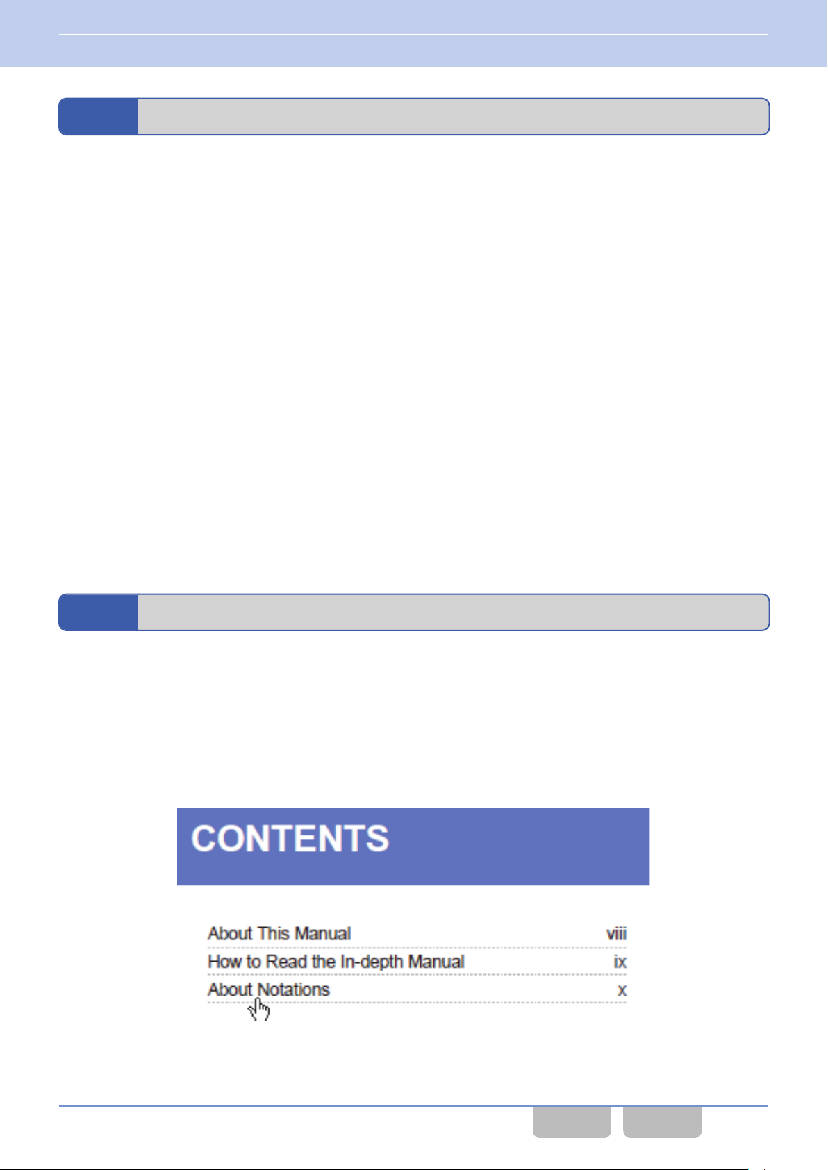
For your convenience of reading through this document using Adobe Acrobat or Adobe Reader, a link to a corresponding
is pasted in the Contents page, Index page, the lower part of each page and in the context. Clicking the portion where
item
a link is pasted enables a jump to the corresponding page.
Placing a pointer over the portion where a link is pasted changes the shape of the pointer to a hand (U).
CONTENTS
Clicking a title in the Contents page allows a jump to the corresponding page.
Common FUNC (K, F)/Ver 2.20 xvi
CONTENTS INDEX
Page 18
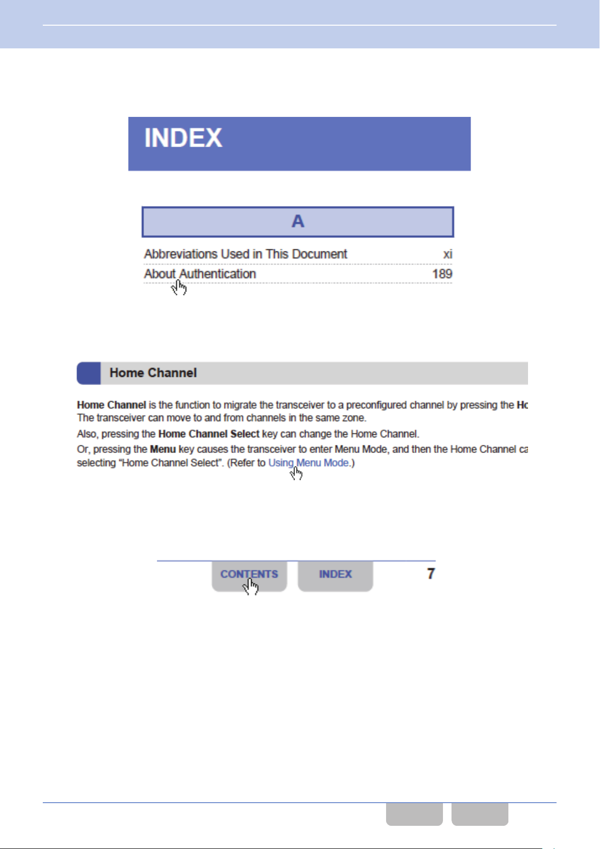
How to Search for Information
INDEX
Clicking a function name, a title or a page number in the Index pages allows a jump to the corresponding page.
Blue Characters in the Main Text
Clicking a portion with blue characters in the main context allows a jump to the corresponding page.
Blue Characters at the Bottom of Each Page
Clicking a portion with blue characters located at the bottom of each page allows a jump to the first page of the contents or
index.
Return to the Previous Page
To return to the previous page, click the “Previous Page” button on your Adobe Acrobat or Adobe Reader, or press the [M]
key while pressing and holding the [Alt] key on the keyboard.
Search the Text
The text in this document can be searched using the search function of your Adobe Acrobat or Acrobat Reader.
Open the Reference in Another FUNC
In this manual, a reference to other FUNC is written as “NXDN FUNC Scan”, for example. Clicking the link opens the
corresponding FUNC page. However, to open the link, the PDF file of each FUNC needs to be stored in the same folder.
Common FUNC (K, F)/Ver 2.20 xvii
CONTENTS INDEX
Page 19

Outline of This Transceiver
Outline of This Transceiver
NX-5200/ NX-5300/ NX-5400/ NX-5700/ NX-5800/ NX-5900 is the VHF/ UHF or 700 MHz/ 800 MHz transceiver for the use
of professionals. The transceiver is equipped with the digital communications system (conventional and trunking) which
complies with the NXDN, P25, and DMR common air interface specifications, as well as the existing analog FM mode.
GENERAL FEATURES
Portable
0
128 Zones, 512 Channels per zone
Models
0
VHF Models
Low: 1 W, High: 6 W
0
UHF Models
Low: 1 W, High: 5 W
0
700 MHz/ 800 MHz Model
Low: 1 W, High: 3 W
Display Functions
0
Color LCD
0
7 Color LED
0
Function/ Status LCD Icons
0
Transmit/ Busy/ Call Alert/ Warn LED
Specifications
0
Emergency/ AUX Key
0
On/ Off Volume Knob
0
16-Position Mechanical Selector
0
2 Position Lever Switch
0
4 Front PF Keys & Cross Key
0
12-Key Keypad (Full key model)
0
3 Customize Keys (Standard key model)
0
3 Side PF Keys
0
Audio Power more than 1 W@8
0
PC Serial Interface
0
Built-in GPS Receiver
0
Built-in Bluetooth
0
microSD card slot
0
Motion Sensor
Others
0
Date & 12/ 24 Hour Time Clock
0
Flash Firmware Upgrading
Mobile
*1
0
128 Zones, 512 Channels per zone
*1
Models
0
VHF Models
Low: 5 W, High: 50 W
0
UHF Models
Low: 5 W, High: 45 W
0
700 MHz/ 800 MHz Model
Low: 2 W, High: 30 W/ 35 W
Display Functions
0
Color LCD
0
7 Color LED
0
Function/ Status LCD Icons
0
Transmit/ Busy/ Call Alert/ Warn LED
Specifications
0
Emergency/ AUX Key
0
4 Up/ Down Selectors & 7 Front PF Keys (Basic
Panel)
0
14 Front PF Keys & 4-Way D-pad Key (Featured
Panel)
0
16-Position Mechanical Selector (Featured
Panel)
0
4 Front PF Keys & Cross Key (Handheld Control
Ω
Head)
0
12-Key Keypad (Handheld Control Head)
0
2 Customize Keys (Handheld Control Head)
0
Front Panel Speaker, 4 W Speaker Audio
0
Illumination Sensor
0
PC Serial Interface
0
DB 25 Accessory Interface
0
9 Programmable AUX I/Os
0
2 Programmable AUX Outputs
0
Microphone
0
Built-in GPS Receiver
0
Built-in Bluetooth
0
microSD card slot
Others
0
Date & 12/ 24 Hour Time Clock
0
Timed Power-off
0
Ignition Sense
0
Public Address/ Horn Alert Output
0
Flash Firmware Upgrading
Common FUNC (K, F)/Ver 2.20 xviii
CONTENTS INDEX
Page 20

Outline of This Transceiver
P25 DIGITAL MODES
GENERAL
0
P25 Digital Air Interface
0
AMBE+2 VOCODER
0
12.5 kHz Channel Spacing
0
Individual Call
0
Group Call
0
Emergency Call
0
All Group Call
0
Radio Inhibit / Uninhibit
0
Remote Monitor
0
Ignition On/ Off GPS Reporting (Mobile only)
0
Single Scan, List Scan
0
AES & DES Encryption Module Option
0
AES/ DES Key Loader Option
0
Over-the-Air-Rekeying
*2
CONVENTIONAL MODE
*2
TRUNKING MODE
0
P25 Phase 1 Conventional
0
Network Access Code (NAC)
0
ALL CALL
0
Priority Scan
0
2-tone
0
Multi-Zone Scan
NXDN DIGITAL MODES
GENERAL
0
NXDN Digital Air Interface
0
AMBE+2 VOCODER
0
6.25 kHz (Very Narrow)/ 12.5 kHz (Narrow) Channel Spacing
0
Over-the-Air Alias
0
Paging Call
0
Emergency Call
0
All Group Call
0
Status Message
0
Remote Stun/ Kill*
0
Remote Monitor
0
Short & Long Messages
0
AUX Input Status Message (Mobile Only)
0
AUX Output Status Message (Mobile Only)
0
Ignition On/ Off GPS Reporting (Mobile only)
0
Data with Voice
0
Single Scan, List Scan
0
NXDN Scrambler Included
0
AES & DES Encryption Module Option
0
AES/ DES Key Loader Option
*3
2
*2
*3
*4
*5
0
P25 Phase 1 Trunking, P25 Phase 2 Trunking
0
Paging Call
0
Telephone Call
0
Priority Monitor Scan
0
Limited Talkgroup Scan
Common FUNC (K, F)/Ver 2.20 xix
CONTENTS INDEX
Page 21

Outline of This Transceiver
CONVENTIONAL MODE
0
63 Radio Access Numbers (RAN)
0
Individual Call & Group Call
0
Mixed FM/ Digital Operation
0
Site Roaming
0
2-tone
0
Multi-Zone Scan
DMR CONVENTIONAL MODES
DMR Digital Air Interface
0
AMBE+2 VOCODER
0
12.5 kHz Channel Spacing
0
Color Code
0
Individual Call
0
Paging Call
0
Group Call & Broadcast Call
0
Unaddressed Call
0
Emergency Call
0
All Group Call
0
0
Status Message
0
Short Messages
0
AUX Input Status Message (Mobile Only)
0
AUX Output Status Message (Mobile Only)
Open Voice Channel Mode (OVCM)
0
Call Interruption
0
Remote Control
0
Ignition On/ Off GPS Reporting (Mobile only)
0
Bit Scramble Encryption
0
Single Scan, List Scan, Multi-Zone Scan
0
AES & DES Encryption Option
0
ARC4 Encryption Option
0
Site Roaming
0
*3
*3
TRUNKING MODE
0
Individual Call
0
Group Call & Broadcast Call
0
Telephone Call
0
Transmission Trunked Mode
0
Message Trunked Mode
0
4 Priority Monitor IDs
0
Remote Group Add
0
Failsoft Mode
*4
*5
*6
*2
*6
*6
Common FUNC (K, F)/Ver 2.20 xx
CONTENTS INDEX
Page 22
Outline of This Transceiver
ANALOG MODES
GENERAL
0
12.5 kHz (Narrow)/ 20.0 kHz (Wide 4k) (NX-5400/ NX-5900 only)/ 25.0 kHz (Wide) Channel Spacing
0
Conventional & LTR Systems
0
FleetSync/ FleetSync II, MDC-1200, DTMF
0
QT/ DQT/ 2-tone
0
Single Scan, List Scan
0
Priority Scan
0
Multi-Zone Scan
0
Voice Inversion Scrambler (16 Codes)
FleetSync
0
PTT ID/ Caller ID
0
Selective/ Group Call
0
Status Message
0
Emergency, Short & Long Messages
0
AUX Input Status Message (Mobile Only)
0
AUX Output Status Message (Mobile Only)
0
Ignition On/ Off GPS Reporting (Mobile only)
*3
*3
*4
*5
MDC-1200
*7
0
PTT ID/ Caller ID
0
Selective/ Group Call
0
Radio Check, Radio Inhibit/ Uninhibit
0
AUX Output ID (Mobile Only)
*5
5-tone
0
Selective/ Group Call
0
Status Message
0
Emergency Call
*1
The maximum number of channels that can be configured for a transceiver in total is 1,024. With the Radio Feature
License (KWD-5000CH) enabled, the maximum number of configurable channels can be extended to 4,000. The
maximum number of Talkgroup IDs that can be configured in a P25 Trunking system is 512.
*2
The supported PC software and external devices need to be separately prepared for the transmitting transceiver.
*3
To send messages or data with serial communications, the supported PC software and external devices need to be
separately prepared for the transmitting transceiver. In addition, to send the received messages or data to external
devices, the supported PC software and external devices need to be separately prepared for the receiving transceiver.
*4
sensor to detect the change of port status needs to be attached to the AUX Input port for the transmitting transceiver.
A
*5
To remotely control external devices according to the change of port status, the external devises need to be connected
to the AUX Output port for the receiving transceiver.
*6
These trunking functions rely on the programming and operation of the system. Priority Monitor also requires NX
subscriber settings.
*7
For KPG-D1N, “Wide” cannot be configured in Channel Spacing if a receive frequency or a transmit frequency is
configured in the following ranges:
VHF: above 149.98750 MHz and less than 174.01250 MHz
UHF: above 420.98750 MHz and less than 470.01250 MHz
Common FUNC (K, F)/Ver 2.20 xxi
CONTENTS INDEX
Page 23

Revision History
Revision History
Date Description
1) Added NX-5900 (700/ 800 MHz model) as a supported model.
2) Added the information of KCH-20R (Featured Panel) as a supported Control Head.
3) Added KPG-36X and KPG-46X as supported programming cables.
4) Changed the description in “About this Manual” as follows:
0
Changed the version information
0
Changed the Left Up key to the [+] key
0
Added Radio Feature License
5) Added terms to “Abbreviations Used in this Document”.
6) Added “About Multi RF Deck/ Multi Control Head”.
7) Added option information to “About Options to Use the Functions Described in this Document”.
8) Added supported functions to “Outline of this Transceiver”.
9) Added references for the following functions in “CONTENTS BY PURPOSE”:
0
VOX
0
Multi RF Deck/ Multi Control Head
10) Added “KCH-20R (Featured Panel)” and “External Microphone (KMC-25)” in “1 FUNCTIONS AND PANEL LAYOUT”.
11) Added “Mobile (KCH-20R (Featured Panel))” in “1.3 About LCD”.
12) Added “2.2 Connecting the Transceiver to a PC by Bluetooth”.
13) Added the description of DFA Data Erase in the notes of “2.3 Writing the Configuration Data to the Transceiver”.
14) Added the following items in “2.3 Writing the Configuration Data to the Transceiver”:
Writing configuration data to multiple transceivers using Bluetooth communication
About the writing of configuration data in a Multi RF Deck/ Multi Control Head structure
15) Added “2.5 Writing Configuration Data Using Wireless Communication (OTAP)”.
16) Added the Function Modes for using Mode Reset Timer to Table 3-3.
17) Added Direct Channel & OST to Table 3-4.
18) Added the description of the analog system in “Manual Dialing”.
19) Added the description of the analog system and Table 3-6 in “3.7 Viewing the Receive History (Stack)”.
2015.11.30
20) Added “Scroll Display” in “3.8 Operating the Transceiver in Each Mode (Common Operation)”.
21) Added the following items to Table 3-8:
0
Volume Control
0
Mobile (KCH-20R (Featured Panel))
22) Added “3.10 Operations in a Single RF Deck/ Dual Control Head”.
23) Added “3.11 Switching the Display”.
24) Added the transmission power of NX-5900 to Table 4-2.
25) Added the information of an LTR Trunking system to the following items:
4.3 Channel Spacing
4.2 Transmit Power
4.4 Beat Shift
Using Sound to Notify the Timing to Start Communications (PTT Proceed Tone)
Using Sound to Notify the Other Party that the Communication Ends (PTT Release Tone)
External PTT (Data)
Data PTT
DTC
Available Functions for AUX Output Ports
12.2 Controlling Vehicle Operation According to the State of the Horn Alert Port (Horn Alert)
Available Functions for the PF Keys
Available Functions for Menu Mode
26) Added the description related to the “DFA” display in “4.5 Displaying the Signal Strength Level (RSSI Level) (Maintenance
Display)”.
27) Added the notes related to the behavior when in a Multi RF Deck/ Multi Control Head structure to the following items:
4.5 Displaying the Signal Strength Level (RSSI Level) (Maintenance Display)
5.5 Changing the Brightness of the Backlight (LCD Brightness)
5.7 Automatically Adjusting the Brightness Level of the LCD (Auto Dimmer)
Common FUNC (K, F)/Ver 2.20 xxii
CONTENTS INDEX
Page 24

Revision History
Date Description
28) Added the items of Analog and LTR Trunking to Table 5-1.
29) Added the description of “Full Color White” in “5.6 Changing the Color Scheme of the Transceiver Display (Color
Scheme)”.
30) Added a supported icon to Table 5-2.
31) Added the description of “FleetSync ID” in “Power-on Text”.
32) Added “Sub-LCD Display Priority” in “5.10 Display Functions of the Display”.
33) Added the description of the screen size in Mobile (Featured Panel) in “5.12 Displaying a Bitmap Image When the
Transceiver is Turned ON (Custom Start-up Screen)”.
34) Added the description of the supported tones in “6.1 Tones that Sound When a User Operates the Transceiver or When
the Transceiver Status Is Changed” and “6.2 Tones that Sound When the Transceiver Receives a Call”.
35) Added notes and “About the Behavior When Using KAP-2” in “6.5 Using the Transceiver as a Megaphone (Public
Address)”.
36) Added “Microphone 7” to Table 6-13.
37) Changed the configuration range of “Microphone Sense/ External Microphone Sense”.
38) Changed the configuration range of “Digital Audio Offset”.
39) Added the function description for Mobile and the following items in “7 BATTERY”.
7.6 Displaying the Remaining Battery Power When the Transceiver Is Turned ON (Power-on Battery Information)
7.7 Checking the Detailed Information of a Battery (Battery Information Display)
40) Added the information of MDC-1200/ FleetSync/ 2-tone/ DTMF to Table 9-2.
41) Added notes in “9.2 Recording Received Audio Automatically (Auto Recording)”.
42) Added notes in “9.4 Storing the GPS Data (GPS Data Storage)”.
43) Added notes in “10.1 Toggling Bluetooth On/ Off”.
44) Added the description related to the device class of the transceiver in “About the Displayed Contents of a Bluetooth-
compatible Device”.
45) Added the following items in “10.2 Finding a Bluetooth-compatible Device (Bluetooth Find Device)”:
Configuring the Bluetooth Device Name of the Transceiver (Bluetooth Device Name)
Checking the Bluetooth Device Name (Bluetooth Information)
Responding to the Search of a Bluetooth-compatible Device (Bluetooth Discoverable)
46) Added the descriptions of Headset Profile and Serial Port Profile in “Receiving a Pairing Request from a Bluetooth-
2015.11.30
compatible Device”.
47) Corrected the descriptions on the available operations in “10.4 Displaying a Bluetooth-compatible Device (Bluetooth My
Devices)”.
48) Added the description on the volume level of the received audio of a Bluetooth-compatible device in “Connecting by
Headset Profile”.
49) Added the description on how to reset a Headset Profile connection in “Resetting the Connection by Headset Profile”.
50) Added “10.6 About Serial Port Profile (SPP Connection/ SPP Disconnection)”.
51) Added “Determining the Speaker to Emit by Linking with the Microphone Hook (Off-hook Speaker Revert)” in “10.8
Resetting the GPS/ Bluetooth Device (GPS/Bluetooth Reset)”.
52) Added “10.9 Configuring the Connection Destination of a Bluetooth-compatible Device (Bluetooth Interface Selection)”.
53) Added the items of Analog Conventional/ LTR Trunking to Table 11-2.
54) Added the items of External PTT (PA) to Table 11-3.
55) Added “External PTT (PA)” to “11.2 D-sub 25-pin Connector”.
56) Added the information of DTMF, 2-tone, and FleetSync in “Call 1 to Call 6” of “11.2 D-sub 25-pin Connector”.
57) Added the following items to Table 11-8:
0
AUX Output ID 1 to AUX Output ID 3
0
Encryption
58) Added “11.3 Selecting the Audio Input Line If Detaching and Using Control Head (Control Head Mic Input)”.
59) Added the description of Analog Conventional in “12.2 Controlling Vehicle Operation According to the State of the Horn
Alert Port (Horn Alert)”.
60) Added “16 MULTI RF DECK/ MULTI CONTROL HEAD”.
61) Added “17 STRUCTURES OF MULTI RF DECK/ MULTI CONTROL HEAD”.
62) Added “18 VOX”.
63) Added supported functions in “Available Functions for the PF Keys”. Added the note on the configuration restrictions of
functions with “(Continuous)” in the function names.
64) Added Function Mode to “Table 1-2 Function Mode”.
65) Added the note in “Available Functions for the PF Keys” about functions in common with Primary and Secondary.
66) Added supported functions in “Available Functions for Menu Mode”.
67) Added “COM port Bluetooth” in “Available Functions for COM Port”.
68) Added notes in “Available Functions for COM Port”.
Common FUNC (K, F)/Ver 2.20 xxiii
CONTENTS INDEX
Page 25

Revision History
Date Description
69) Added the note in “Flow Control of the Communication Port (Flow Control)”.
2015.11.30
2016.9.30
70) Added the keys of KCH-20R (Featured Panel) to the table in “Key Operations for Each Mode”.
71) Changed the version number from 1.00 to 1.60.
1) Added the DMR and 5-tone information in “About this Manual” and “How to Read the In-depth Manual”.
2) Added “DMR CONVENTIONAL MODES” in “Outline of this Transceiver”.
3) Added “5-tone” to “ANALOG MODES” in “Outline of this Transceiver”.
4) Added the following items in “Mode Reset Timer”:
Forward Mode, Free-dial Entry Mode, Lone Worker ON/OFF Mode, My ID Mode, OVCM Mode, Remote Control Mode,
Receive Entry Mode, SD Card Direct Access Mode
5) Added the description of the operation in a DMR Conventional system to Table 3-4.
6) Added “Free-dial Entry” to Table 3-4.
7) Added the DMR and 5-tone information in “3.7 Viewing the Receive History (Stack)”.
8) Added “Mic Key” to Table 3-9.
9) Added the note about Mic Key in “3.9 Locking the Transceiver Keys (Key Lock)”.
10) Added the description of the specifications in a DMR Conventional system in “4.3 Channel Spacing”.
11) Added the description of the behavior when the Multi-System Roaming and Multi-System Hunt functions are used to
“NXDN Trunking system” in “4.5 Displaying the Signal Strength Level (RSSI Level) (Maintenance Display)”.
12) Added “DMR Conventional” to Table 5-1.
13) Added the description of LCD Brightness for Control Head 2 to the note in “5.5 Changing the Brightness of the Backlight
(LCD Brightness)”.
14) Added the description of Auto Dimmer for Control Head 2 to the note in “5.7 Automatically Adjusting the Brightness Level
of the LCD (Auto Dimmer)”.
15) Added the description of the following icons to Table 5-2:
System Lock icon, OVCM icon
16) Added the following tones to Table 6-1:
Transaction Confirmed Tone, Record Stopped Tone, Advanced GPS Report Error Tone, Low SD Memory Tone
17) Added the description of the following tones to Table 6-3:
Transaction Confirmed Tone, Record Stopped Tone
18) Added the description of the following tones to Table 6-4:
Advanced GPS Report Error Tone, Low SD Memory Tone
19) Added the description of various Alert Tones in a DMR Conventional system to Table 6-10.
20) Added “6.8 Using Voice Guidance (Voice Announcement)”.
21) Added the description of the specifications in a DMR Conventional system in “7.5 Reducing Battery Consumption (Battery
Saver)”.
22) Replaced the diagram of Figure 9-1.
23) Added the description about Voice Memo in “Folder Structure of a microSD Card”.
24) Added the following items in “9.1 About microSD Card”:
Configuring the Warning Behavior for the Remaining Memory Capacity (Low Memory Warning)
Configuring the Storage Method of an Audio Data File (First-in First-out Deletion)
25) Added the description of the behavior when 5-tone signaling is used to Table 9-2.
26) Added notes in “9.2 Recording Received Audio Automatically (Auto Recording)”.
27) Added “9.3 Recording Audio to a microSD Card (Voice Memo)”.
28) Added and changed the description of the operation in “9.4 Playing Back the Recorded Audio (Playback)”.
29) Added “Storing Audio Data in the Saved Folder” in “9.4 Playing Back the Recorded Audio (Playback)”.
30) Added “9.6 Confirming microSD Card Contents via a PC (SD Card Direct Access)”.
31) Added “Configuring the Headset Profile Connection Sequence (Bluetooth Headset Connection Type)” in “10.5 About
Headset Profile (HSP Connection/ HSP Disconnection)”.
32) Added the description of the behavior in a DMR Conventional system in “Using the Vibrator”.
33) Added the description of the behavior in a DMR Conventional system and the description of the behavior when 5-tone
signaling is used in “Available Functions for AUX Input Ports”.
34) Added the description of the behavior in a DMR Conventional system in “Available Functions for AUX Output Ports”.
35) Added the description of the behavior in a DMR Conventional system in “Conditions to Activate the Horn Alert”.
36) Added “Configuring the Output Method of the Received Audio and Beep (Multi RF Deck Audio Output Type)” in “16.7
Audio Function”.
Common FUNC (K, F)/Ver 2.20 xxiv
CONTENTS INDEX
Page 26

Revision History
Date Description
37) Added “16.18 Relaying the Received Signal (Mobile Relay Station)”.
38) Added “17.1 Initial Configuration for Multi RF Deck/ Multi Control Head”.
39) Added “17.13 About the Pin Arrangement for KCT-72 When an External Device is Connected”.
40) Added the following items to Table 19-1:
Call Interruption, Digit 10x Down, Digit 10x Up, Digit 1x Down, Digit 1x Up, Mobile Relay Station, OVCM, Receive Entry,
Remote Control, RF Deck Down, RF Deck Up, System Down, System Down (Continuous), System Lock, System Select,
System Up, System Up (Continuous), Transfer, Voice Memo
2016.9.30
2017.1.31
41) Added the following items to Table 19-2:
Mobile Relay Station, Receive Entry, Remote Control, System Select, Voice Memo
42) Added the following items to Table 19-3:
Bluetooth Headset Connection Type, OVCM, Receive Entry, Remote Control, System Lock, System Select, Transfer,
Voice Memo
43) Corrected the description of the operation of “Playback Mode” in “20 KEY OPERATIONS FOR EACH MODE”.
44) Added the following items in “21 BEEP LIST”:
Record Stopped Tone, Low SD Memory Tone
45) Changed the version number from 1.60 to 2.00.
1) Changed the version information in “About This Manual”. Added the information of KCH-21R (Handheld Control Head).
2) Added the operating portion of KCH-21R (Handheld Control Head) to “GENERAL FEATURES”.
3) Added “KCH-21R (Handheld Control Head)” to “1.2 NX-5700/ NX-5800/ NX-5900”.
4) Added “Mobile (KCH-21R (Handheld Control Head))” to “LCD” in “1.3 About LCD”.
5) Added “Mobile (KCH-21R (Handheld Control Head))” to “Icons” in “1.3 About LCD”.
6) Added the screen of KCH-21R (Handheld Control Head) to “Key Guide” in “1.3 About LCD”.
7) Added “About Displayed Stack Data” to “3.7 Viewing the Receive History (Stack)”.
8) Added “Mobile (KCH-21R (Handheld Control Head))” to Table 3-11.
9) Added the description of KCH-21R (Handheld Control Head) to “5.5 Changing the Brightness of the Backlight (LCD
Brightness)”.
10) Added the note in “5.7 Automatically Adjusting the Brightness Level of the LCD (Auto Dimmer)”.
11) Added the size of the bitmap image that can be used for KCH-21R (Handheld Control Head) to “5.12 Displaying a Bitmap
Image When the Transceiver is Turned ON (Custom Start-up Screen)”.
12) Added the restriction of the Minimum Volume Type configuration to “Configuring the Minimum Volume Level (Minimum
Volume)”.
13) Changed “About the Behavior When Using KAP-2” to “About the Speaker to Emit Audio” in “6.5 Using the Transceiver as
a Megaphone (Public Address)”.
14) Added “Speaker 7” to Table 6-13. Changed the speakers that supports “Internal Speaker” and “Speaker 3”.
15) Changed “Resetting the Recognition of microSD Card” to “Removing the microSD Card” in “9.1 About microSD Card”.
16) Corrected the note in “About the Audio to Be Recorded”.
17) Changed “Configuring the Headset Profile Connection Sequence (Bluetooth Headset Connection Type)” to “If Pairing of
a Bluetooth-compatible Device Cannot Occur or If a Bluetooth-compatible Device Does Not Behave (Bluetooth Headset
Connection Type)”. Added the table description and the note.
18) Added the description of KCH-21R (Handheld Control Head) to “Connecting by Serial Port Profile”.
19) Added the description of KCH-21R (Handheld Control Head) to “10.9 Configuring the Connection Destination of a
Bluetooth-compatible Device (Bluetooth Interface Selection)”.
20) Added the description of KCH-21R (Handheld Control Head) to “Light Sense” in “Available Functions for AUX Input
Ports”.
21) Added the note in “11.3 Selecting the Audio Input Line If Detaching and Using Control Head (Control Head Mic Input)”.
22) Added the description of KCH-21R (Handheld Control Head) to “15.6 Checking the Firmware Version (Transceiver
Information Mode)”.
Common FUNC (K, F)/Ver 2.20 xxv
CONTENTS INDEX
Page 27

Revision History
Date Description
23) Added the description of KCH-21R (Handheld Control Head) to the following items:
16.1 Description
16.5 Basic Operations
16.16 Bluetooth Communication
17.9 Changing the Display Positions of a Channel Name and an Icon When Multi RF Deck View Is On
“Multi RF Deck View” in “19.1 Available Functions for the PF Keys”
2017.1.31
2017.6.30
20 KEY OPERATIONS FOR EACH MODE
24) Added the description of communication ports to “Connecting the RF Deck by Using a D-sub 25-pin Cable”.
25) Changed the DIP switch image in “About the Connection of the Control Head to the RF Deck”.
26) Corrected “Adding an RF Deck” as follows:
Changed the reference described in the note of step 2.
Moved the note of step 5 to the operation procedure.
Corrected the note of step 5.
27) Changed the version number from 2.00 to 2.10.
1) Changed the version information in “About This Manual”.
2) Added the reference for “Optional Signaling LED” in “Indication and Display” of “CONTENTS BY PURPOSE”.
3) Added “List+”, “List-” and “View” to Table 1-1.
4) Added the note about Power-on Tone in “Turning the Transceiver ON”.
5) Added “System Select Mode” to Table 3-3.
6) Changed the overall description in “3.7 Viewing the Receive History (Stack)”.
7) Added the following items in “3.7 Viewing the Receive History (Stack)”:
Configuring the Display Order of Data in Stack Mode (Stack Order)
Enabling the Storage of Redundant Data (Repeated Calls Stack)
Displaying the Caller ID when Displaying a Message (Caller ID for Message)
Displaying the Receive Channel (Channel Name (Message Display))
8) Changed the function names as follows:
Latest Received Message Stack
ID/Message Stack with Time Stamp
9) Added that the PTT switch is also locked in “3.9 Locking the Transceiver Keys (Key Lock)”.
10) Added “PTT” to the configuration items in Table 3-18.
11) Added the description of a DMR Conventional system in “4.4 Beat Shift”.
12) Changed “4.5 Displaying the Signal Strength Level (RSSI Level) (Maintenance Display)” to “4.5 Displaying the Signal
Strength Level (RSSI Level, BER) (Maintenance Display)”. Added the description related to the BER display.
13) Added “5.4 Optional Signaling LED”.
14) Added the Encryption (ARC4) icon to Table 5-2.
15) Added “Configuring a tone which sounds when the transceiver is turned ON (Power-on Tone)” in “Power-on Tone”.
16) Changed “Temporarily Reducing the Volume Level of the Speaker Microphone (Speaker Attenuation)” to “Temporarily
Reducing the Volume Level of the Speaker (Speaker Attenuation)”. Deleted the description of the supported models
(Mobile is also supported). Added that the transceiver speaker and Bluetooth speaker are also supported. Corrected the
note.
17) Corrected the note related to the microphone input line of the External PTT (PA) port in “6.5 Using the Transceiver as a
Megaphone (Public Address)”.
18) Corrected the note in “Conditions that enables audio data file and GPS data file to be stored in a microSD card”.
19) Added the description related to the internal memory in “Configuring the Storage Method of an Audio Data File (First-in
First-out Deletion)”. Added the description related to the backing up of audio data.
20)
Added the conditions of when Auto Recording does not start in “
number of recordings has been reached”. Deleted the description about the SELF TESTING display of the transceiver
when audio data is deleted from the internal memory.
21)
Added the notes in “
22) Deleted the description about the SELF TESTING display of the transceiver when GPS data is deleted from the internal
memory in the note of “9.5 Storing the GPS Data (GPS Data Storage)”.
R
Deleting an audio data folder” of “9.4 Playing Back the Recorded Audio (Playback)”.
N
Old Message Overwrite
N
Time Stamp
R
If Auto Recording does not start because the maximum
Common FUNC (K, F)/Ver 2.20 xxvi
CONTENTS INDEX
Page 28

Revision History
Date Description
23) Added “External Speaker” to Table 11-3.
24) Added “External Speaker” in “Available Functions for AUX Input Ports”.
25) Added the description about Conventional Channel (DMR) in “TOR” to Table 11-8.
26) Added the note to “AUX Output Status Message 1 to AUX Output Status Message 3” in Table 11-8.
27) Added “Digital Mode” and “Out of Range” to Table 11-8.
28) Deleted “External PTT (PA) port” from the descriptions of “Modulation Line” in Table 11-9.
29) Added the note in “The Amount of Time Until the Transceiver Is Turned OFF (Timed Power-off)”.
30) Corrected the description of when the microSD card is not inserted in “Recording Received Audio Automatically (Auto
Recording)”.
31) Added the description of DMR Conventional in the following items of Table 19-1. Added “Manual Site Hunt”.
Group
Group + Short Message
2017.6.30
Group + Status
Individual
Individual + Short Message
Individual + Status
Short Message
Status
32) Added “Manual Site Hunt” to Table 19-1.
33) Corrected the description of “Speaker Attenuation” in Table 19-1. “This function can be assigned only to the PF 1 and PF
2 keys on a microphone. Deleted ”. Deleted “(Portable only)”.
34) Corrected the description of “Stack Mode” in “20 KEY OPERATIONS FOR EACH MODE”.
35) Corrected the descriptions of the operation to change the display of “Maintenance Display Mode (NXDN Trunking)” in “20
KEY OPERATIONS FOR EACH MODE”.
36) Changed the version number from 2.10 to 2.20.
Common FUNC (K, F)/Ver 2.20 xxvii
CONTENTS INDEX
Page 29
CONTENTS BY PURPOSE
Basic
Configurations
for Using the
Transceiver
Configuring Various Functions for the
Transceiver
Frequencies and signaling for transmission and
reception, channel data, including the transmit
power, and other functions required for various
communications,
Group Call, can be configured by using KPG-D1/
D1N.
GETTING STARTED
such as an Individual Call or a
Page 20
Writing the Configuration Data to the
Transceiver
The data configured by using KPG-D1/ D1N can
be written to the transceiver. Writing the data
configured by using KPG-D1/ D1N to the
transceiver allows the transceiver to work
according to the configuration data.
Writing the Configuration Data to the
Transceiver
Page 22
Assigning Functions to the Keys on the
Transceiver
Various functions can be assigned to the PF
keys on the transceiver.
Available Functions for the PF Keys
Page 393
Reading the Configuration Data from the
Transceiver
The configuration data in the transceiver can be
read into KPG-D1/ D1N. By reading the
configuration data written in the transceiver into
KPG-D1/ D1N, the configuration data can be
changed or written to another transceiver.
Reading the Configuration Data from the
Transceiver
Page 23
Transmission
/ Reception
Changing Transmit Power
The transmission power of the transceiver can
be changed to high power, medium power, or
low power.
Transmit Power
Page 77
Using Function Keys
Pressing a key to which a function is assigned
can activate the assigned function or place the
transceiver in various Function Modes.
Using Function Keys
Page 29
Executing a Function by Selecting the
Function from the Menu
Selecting functions in Menu Mode activates
various functions or places the transceiver in
various Function Modes.
Using Menu Mode
Page 37
Changing the Input Sensitivity of the
Microphone
The input sensitivity of the microphone can be
changed.
Microphone Sense/ External Microphone
Sense
Page 131
Viewing the Receive History
Various received messages and callers who
made calls can be viewed.
Viewing the Receive History (Stack)
Page 49
Transmitting Just by Audio Input to a
Microphone
By using the VOX function, audio can be
transmitted
without pressing the PTT switch.
VOX
just by audio input into a microphone
Page 389
Common FUNC (K, F)/Ver 2.20 xxviii
CONTENTS INDEX
Page 30
CONTENTS BY PURPOSE
Indication
and Display
Lighting the LED While Transmitting and
Receiving
The transceiver can light or flash the LED while
the transceiver is transmitting or receiving.
Busy LED
Page 88
Transmit LED
Page 88
Selective Call Alert LED
Page 89
Optional Signaling LED
Page 90
Displaying a Bitmap Image When the
Transceiver is Turned ON
A desired bitmap image can be displayed on the
transceiver display when the transceiver is
turned ON.
Displaying a Bitmap Image When the
Transceiver is Turned ON (Custom Start-up
Screen)
Page 104
Displaying the Transceiver Received Signal
Strength
The received signal strength of the transceiver
can be displayed on the transceiver display.
Displaying the Signal Strength (Signal
Strength Indicator)
Page 99
Displaying the Remaining Battery Power
Level (Portable Only)
A user can be notified on the level of the
remaining battery power on the LCD and by
LED.
Displaying the Remaining Battery Power
Level (Battery Indicator)
Page
144
Sound
Security
Tones Used for the Transceiver
Various tones sound from the transceiver
according to the operation of the transceiver.
Tones
that Sound When a User Operates the
Transceiver or When the Transceiver Status
Is Changed
Page 105
Using a Password to Protect the
Transceiver
A user can set a password to the transceiver so
that the transceiver cannot be used by others
without the user’s permission.
Password for Transceiver Operation
(Transceiver Password)
Page 234
Changing the Calling Alert Tone
Tones that sound from the transceiver when the
transceiver receives a call using optional
signaling or a status message can be changed
to the desired tone.
Tones that Sound When the Transceiver
Receives a Call
Page 114
Using a Password to Protect the
Configuration Data of the Transceiver
To prevent the configuration data of the
transceiver
permission, or to prevent the configuration data
written in the transceiver from being diverted, a
password can be set for the configuration data.
Password When Reading Configuration Data
in a PC (Read Authorization Password)
from being altered without the user’s
Page 235
Password for Writing Configuration Data
(Overwrite Password)
Page 236
Common FUNC (K, F)/Ver 2.20 xxix
CONTENTS INDEX
Page 31
CONTENTS BY PURPOSE
Functions of
Transceivers
for Vehicles
Turning the Transceiver ON or OFF by
Linking with a Vehicle Ignition
For Mobile, the transceiver can automatically be
turned ON or OFF by linking with the status of
the port linked with the vehicle ignition by using
the ignition-linked function.
Turning the Transceiver ON or OFF
According to the State of the Ignition Sense
Port (Ignition Sense)
Page 227
Operating in a Multi RF Deck System by
Connecting Multiple Control Heads and
Transceivers
By connecting 1 or 2 Control Heads to multiple
mobile
transceivers (RF Decks), 1 Multi RF Deck
system can be structured.
MULTI RF DECK/ MULTI CONTROL HEAD
Page 247
Turning the Headlights On of the Vehicle or
Making the Horn Sound When the
Transceiver Receives a Call
For Mobile, by using the horn alert function, the
transceiver can turn the headlights On of a
vehicle to which the transceiver is connected or
make the horn sound when the transceiver
receives a call.
Controlling Vehicle Operation According to
the State of the Horn Alert Port (Horn Alert)
Page 228
Other
Convenient
Functions
Locking the Transceiver Keys
By locking the transceiver keys, a user can avoid
erroneous operation of the transceiver caused
by physically contacting the transceiver while
carrying it around the waist, etc.
Locking the Transceiver Keys (Key Lock)
Page 70
Recording the Received or Transmitted
Audio (Optional)
By using the internal memory of the transceiver
or by using a microSD card or microSDHC card
mounted on the transceiver, the transmitted or
received audio can be recorded. The recorded
audio can be played back on the transceiver.
Recording Received Audio Automatically
(Auto Recording)
Page 160
Reducing Battery Consumption (Portable
Only)
The power consumption of the transceiver can
be reduced by setting the transceiver receiving
intermittently.
Reducing Battery Consumption (Battery
Saver)
Page 147
Displaying the Location Information of the
Transceiver
By using an internal or optional GPS receiver
unit,
the transceiver can display the own location
information on the display.
GPS POSITION DISPLAY
Page 150
Common FUNC (K, F)/Ver 2.20 xxx
CONTENTS INDEX
Page 32
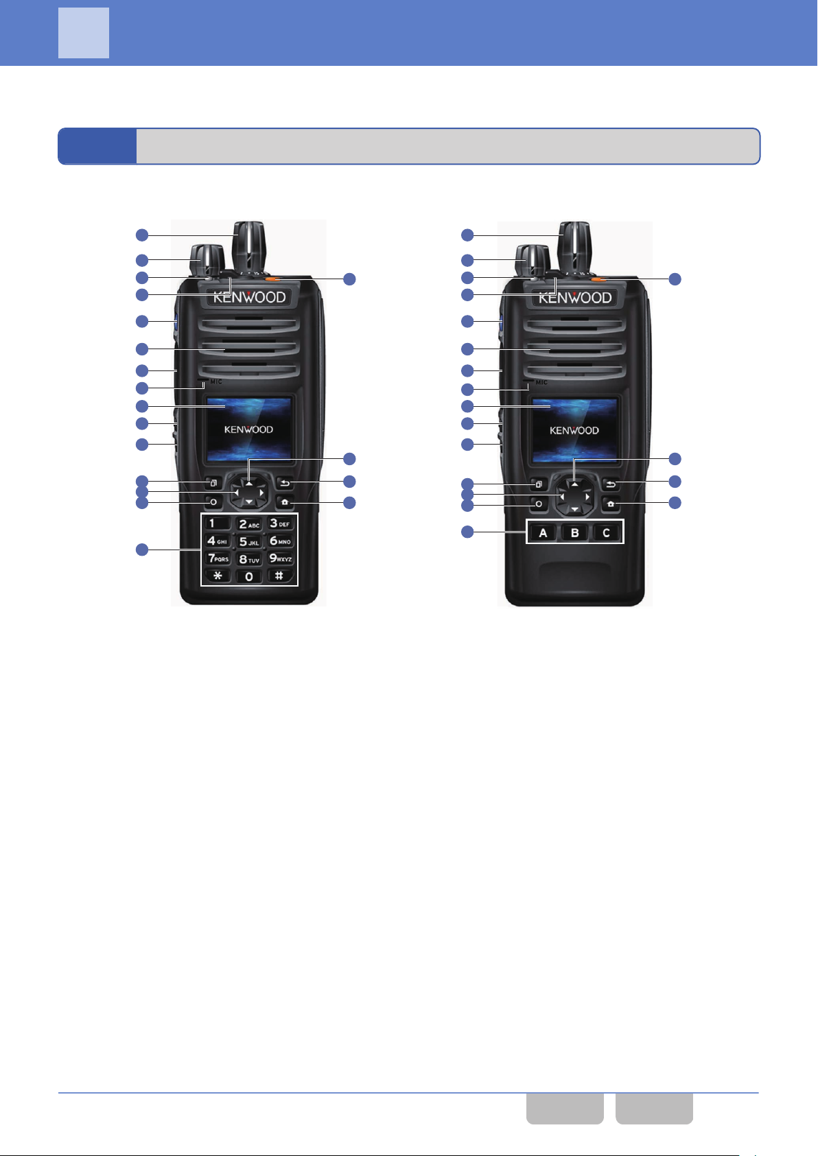
1
2
3
6
7
8
10
13
17 18
11
12
14
15
16
5
4
9
19
Full Key Model Standard Key Model
1
2
3
6
7
8
10
13
17
18
11
12
14
15
16
5
4
20
9
1 FUNCTIONS AND PANEL LAYOUT
1
FUNCTIONS AND PANEL LAYOUT
1.1
NX-5200/ NX-5300/ NX-5400
Figure 1-1 NX-5200/ NX-5300/ NX-5400 Front View
Selector
A
The preassigned function will be activated or will be
changed
the zone or channel.
Power Switch/ Volume Control
B
The transceiver can be turned ON by rotating the Power
switch. The volume level of the speaker sound can be
adjusted.
Transmit LED/ Busy LED
C
These LEDs light when the transceiver transmits or
receives a signal.
AUX Key
D
The preassigned function will be activated or will be
changed to the active state.
Lever Switch
E
The preassigned function will be activated or will be
changed to the active state.
Side 1 Key
F
The preassigned function will be activated or will be
changed to the active state.
Speaker
G
The received audio and the Alert Tone sound from the
speaker.
to the active state. It is normally used to change
H
I
J
K
L
M
N
PTT Switch
Pressing the PTT switch allows transmitting.
Built-in Microphone
LCD
channel number and the transceiver’s status appear
The
on this display.
Side 2 Key
The preassigned function will be activated or will be
changed to the active state.
Side 3 Key
The preassigned function will be activated or will be
changed to the active state.
[G]/ [H] Key
The preassigned function will be activated or will be
changed to the active state. It is normally used to change
the zone or channel.
[Q] (Menu) Key
The preassigned function will be activated or will be
changed to the active state. In this manual, the [Q]
(Menu) key is described as the Menu ([Q]) key.
Common FUNC (K, F)/Ver 2.20 1
CONTENTS INDEX
Page 33

1 FUNCTIONS AND PANEL LAYOUT
1.1 NX-5200/ NX-5300/ NX-5400
O
[O] (Back) Key
The preassigned function will be activated or will be
changed to the active state. In this manual, the [O]
(Back) key is described as the Back ([O]) key.
P
[E]/ [F] Key
The preassigned function will be activated or will be
changed
the zone or channel.
Q
[W] (Function) Key
The preassigned function will be activated or will be
changed to the active state. In this manual, the [W]
(Function) key is described as the Function ([W]) key.
to the active state. It is normally used to change
R
[T] (Home) Key
The preassigned function will be activated or will be
changed to the active state. In this manual, the [T]
(Home) key is described as the Home ([T]) key.
Keypad
S
The transceiver can be operated by pressing a key.
[A]/ [B]/ [C] Key
T
The preassigned function will be activated or will be
changed to the active state.
Common FUNC (K, F)/Ver 2.20 2
CONTENTS INDEX
Page 34
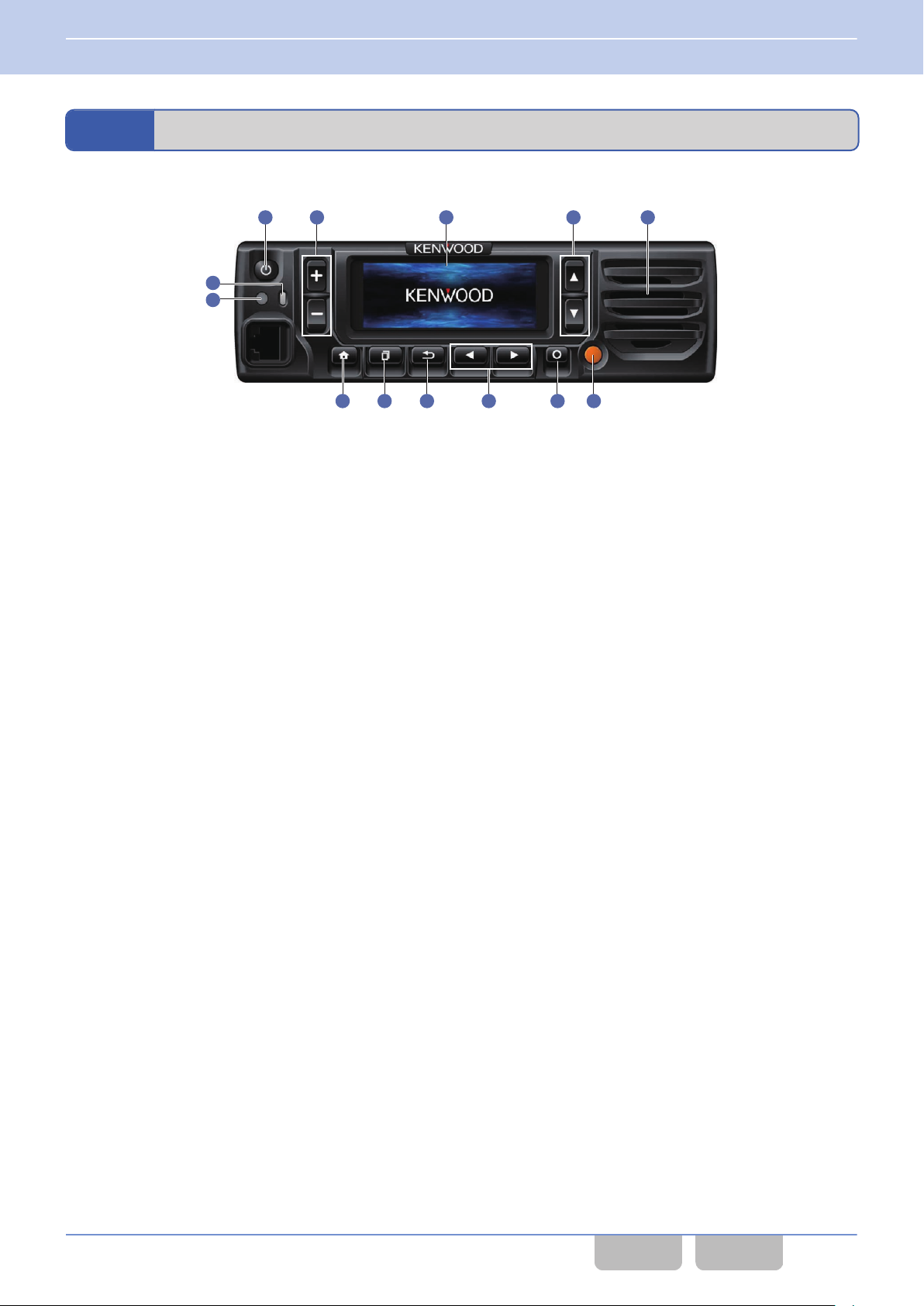
1
2
3
8
9
10 13
11 12
5
4
6
7
1 FUNCTIONS AND PANEL LAYOUT
1.2 NX-5700/ NX-5800/ NX-5900
1.2
NX-5700/ NX-5800/ NX-5900
KCH-19 (Basic Panel)
Figure 1-2 NX-5700/ NX-5800/ NX-5900 Front View (KCH-19 (Basic Panel))
A
[P] (Power) Switch
The
transceiver is turned ON when this switch is pressed
and the transceiver is turned OFF when this switch is
pressed again. In this manual, the [P] (Power) switch is
described as the Power switch.
[+]/ [-] Key
B
The preassigned function will be activated or will be
changed to the active state. It is normally used for the
volume adjustment of the speaker.
LCD
C
The channel number and the transceiver’s status appear
on this display.
D
[G]/ [H] Key
The preassigned function will be activated or will be
changed to the active state. It is normally used to change
the zone or channel.
Speaker
E
The received audio and the Alert Tone sound from the
speaker.
Transmit LED/ Busy LED
F
These LEDs light when the transceiver transmits or
receives a signal.
I
[Q] (Menu) Key
The preassigned function will be activated or will be
changed to the active state. In this manual, the [Q]
(Menu) key is described as the Menu ([Q]) key.
The default of the [Q] (Menu) key is the Menu function.
If the configuration is changed using KPG-D1/ D1N, a
newly configured function will be activated. Unless the
function is reassigned to the [Q] (Menu) key, Menu
Menu
Mode cannot be activated even if the [Q] (Menu) key is
pressed.
J
[O] (Back) Key
The preassigned function will be activated or will be
changed to the active state. In this manual, the [O]
(Back) key is described as the Back ([O]) key.
K
[E]/ [F] Key
The preassigned function will be activated or will be
changed to the active state. It is normally used to change
the zone or channel.
L
[W] (Function) Key
The preassigned function will be activated or will be
changed to the active state. In this manual, the [W]
(Function) key is described as the Function ([W]) key.
AUX Key
Illumination Sensor
G
The sensor is for automatically adjusting the luminance
of the LCD depending on the brightness of the
environment.
H
[T] (Home) Key
The preassigned function will be activated or will be
changed to the active state. In this manual, the [T]
(Home) key is described as the Home ([T]) key.
Common FUNC (K, F)/Ver 2.20 3
M
The preassigned function will be activated or will be
changed to the active state.
CONTENTS INDEX
Page 35
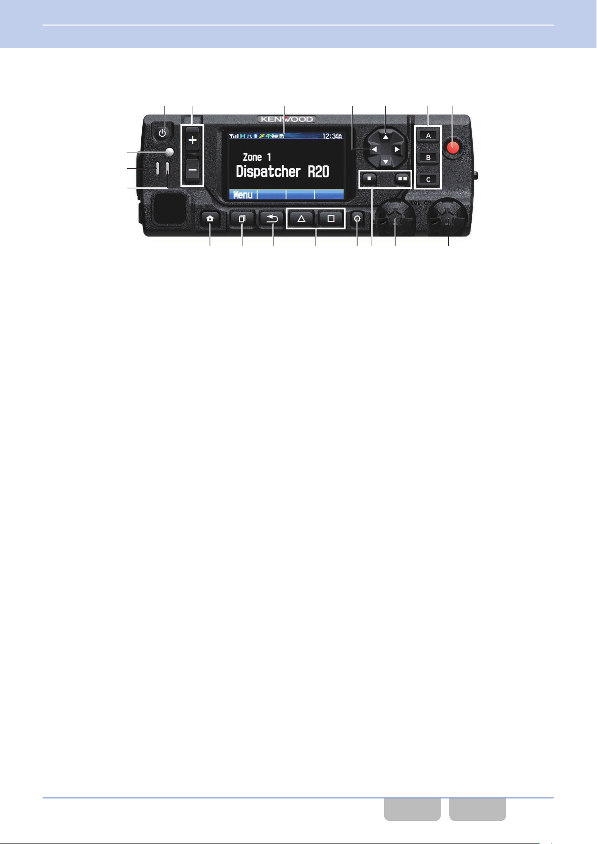
18923
hgedcba
f
56740
1 FUNCTIONS AND PANEL LAYOUT
1.2 NX-5700/ NX-5800/ NX-5900
KCH-20R (Featured Panel)
Figure 1-3 NX-5700/ NX-5800 Front View (KCH-20R (Featured Panel))
A
[P] (Power) Switch
The
transceiver is turned ON when this switch is pressed
and the transceiver is turned OFF when this switch is
pressed again. In this manual, the [P] (Power) switch is
described as the Power switch.
[+]/ [-] Key
B
The preassigned function will be activated or will be
changed to the active state.
LCD
C
The channel number and the transceiver’s status appear
on this display.
D
[E]/ [F] Key
The preassigned function will be activated or will be
changed to the active state. It is normally used to change
the zone or channel.
E
[G]/ [H] Key
The preassigned function will be activated or will be
changed to the active state. It is normally used to change
the zone or channel.
[A]/ [B]/ [C] Key
F
The preassigned function will be activated or will be
changed to the active state.
AUX Key
G
The preassigned function will be activated or will be
changed to the active state.
Illumination Sensor
H
The sensor is for automatically adjusting the luminance
of the LCD depending on the brightness of the
environment.
Transmit LED
I
This LED lights when the transceiver transmits a signal.
Busy/ Status LED
J
This LED lights or flashes according to the status, such
as while the transceiver is receiving a signal, and when
the transceiver receives a call.
K
[T] (Home) Key
The preassigned function will be activated or will be
changed to the active state. In this manual, the [T]
(Home) key is described as the Home ([T]) key.
L
[Q] (Menu) Key
The preassigned function will be activated or will be
changed to the active state. In this manual, the [Q]
(Menu) key is described as the Menu ([Q]) key.
The default of the [Q]
If the configuration is changed using KPG-D1/ D1N, a
newly configured function will be activated. Unless the
Menu function is reassigned to the [Q] (Menu) key, Menu
Mode cannot be activated even if the [Q] (Menu) key is
pressed.
M
[O] (Back) Key
The preassigned function will be activated or will be
changed to the active state. In this manual, the [O]
(Back) key is described as the Back ([O]) key.
N
[d]/ [c] Key
The preassigned function will be activated or will be
changed to the active state.
(Menu) key is the Menu function.
Common FUNC (K, F)/Ver 2.20 4
CONTENTS INDEX
Page 36

1 FUNCTIONS AND PANEL LAYOUT
1.2 NX-5700/ NX-5800/ NX-5900
O
[W] (Function) Key
The preassigned function will be activated or will be
changed to the active state. In this manual, the [W]
(Function) key is described as the Function ([W]) key.
P
[b]/ [b b] Key
The preassigned function will be activated or will be
changed to the active state.
Volume Control
Q
volume level of the speaker sound can be adjusted.
The
Selector
R
The preassigned function will be activated or will be
changed
the zone or channel.
to the active state. It is normally used to change
Common FUNC (K, F)/Ver 2.20 5
CONTENTS INDEX
Page 37
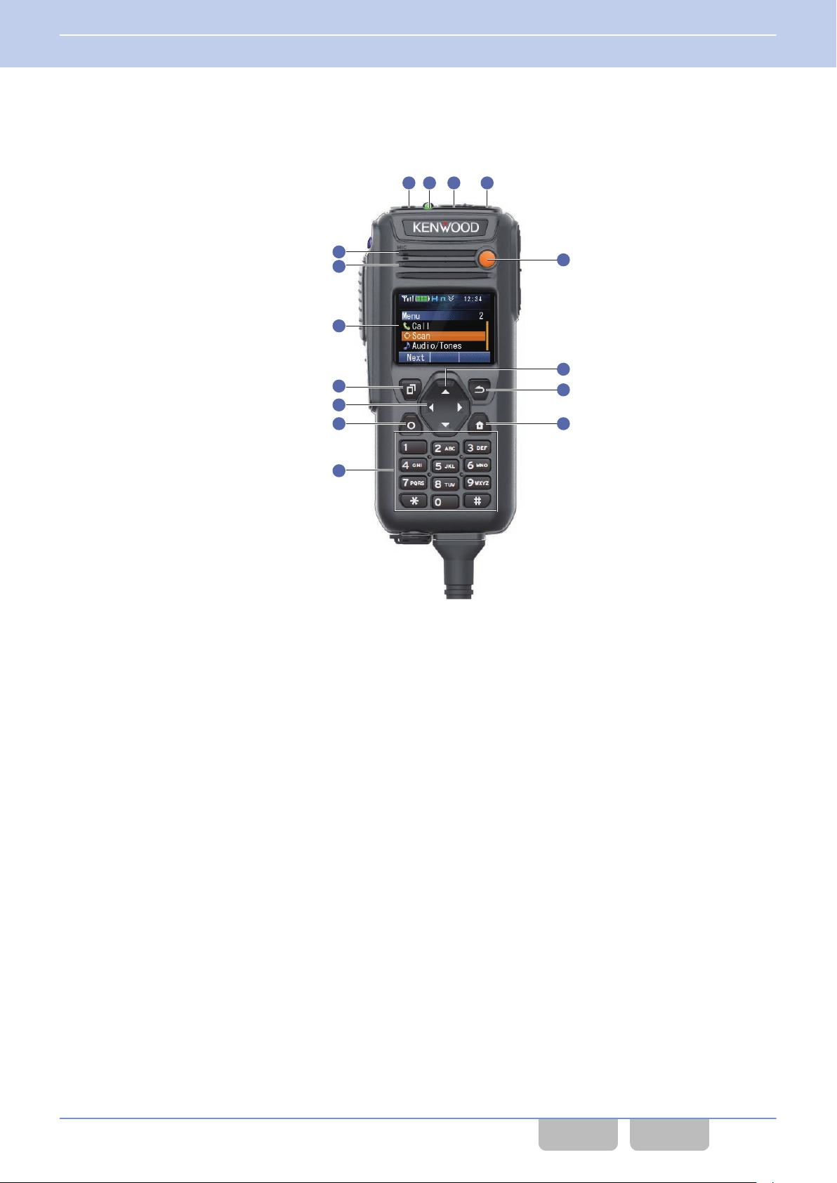
1
2
3
6
7
8
10
13
11
12
14
15
5
4
9
1 FUNCTIONS AND PANEL LAYOUT
1.2 NX-5700/ NX-5800/ NX-5900
KCH-21R (Handheld Control Head)
KCH-21R
be operated in hand as Portable.
is the Handheld Control Head that can be used by connecting to Mobile. By using KCH-21R, the transceiver can
Figure 1-4 KCH-21R (Handheld Control Head) Front View
[A] Key
A
The preassigned function will be activated or will be
changed to the active state.
[B] Key
B
The preassigned function will be activated or will be
changed to the active state.
Transmit LED/ Busy LED
C
These LEDs light when the transceiver transmits or
receives a signal.
Power Switch
D
The
and the transceiver is turned OFF when this switch is
pressed again.
AUX Key
E
The preassigned function will be activated or will be
changed to the active state.
Built-in Microphone
F
Speaker
G
The received audio and the Alert Tone sound from the
speaker.
LCD
H
The channel number and the transceiver’s status appear
on this display.
transceiver is turned ON when this switch is pressed
I
[G]/ [H] Key
The preassigned function will be activated or will be
changed
the zone or channel.
J
[Q] (Menu) Key
The preassigned function will be activated or will be
changed to the active state. In this manual, the [Q]
(Menu) key is described as the Menu ([Q]) key.
K
[O] (Back) Key
The preassigned function will be activated or will be
changed to the active state. In this manual, the [O]
(Back) key is described as the Back ([O]) key.
L
[E]/ [F] Key
The preassigned function will be activated or will be
changed to the active state. It is normally used to change
the zone or channel.
to the active state. It is normally used to change
Common FUNC (K, F)/Ver 2.20 6
CONTENTS INDEX
Page 38

17
18
16
20
19
1 FUNCTIONS AND PANEL LAYOUT
1.2 NX-5700/ NX-5800/ NX-5900
M
[W] (Function) Key
The preassigned function will be activated or will be
changed to the active state. In this manual, the [W]
(Function) key is described as the Function ([W]) key.
N
[T] (Home) Key
The preassigned function will be activated or will be
changed to the active state. In this manual, the [T]
(Home) key is described as the Home ([T]) key.
Keypad
O
The transceiver can be operated by pressing a key.
Figure 1-5 KCH-21R (Handheld Control Head) Side View
Side 1 Key
P
The preassigned function will be activated or will be
changed to the active state.
PTT Switch
Q
Pressing the PTT switch allows transmitting.
Side 2 Key
R
The preassigned function will be activated or will be
changed to the active state.
Side 3 Key
S
The preassigned function will be activated or will be
changed to the active state.
T
]/ [ ] Key
[
The preassigned function will be activated or will be
changed to the active state. It is normally used for the
volume adjustment of the speaker.
Common FUNC (K, F)/Ver 2.20 7
CONTENTS INDEX
Page 39
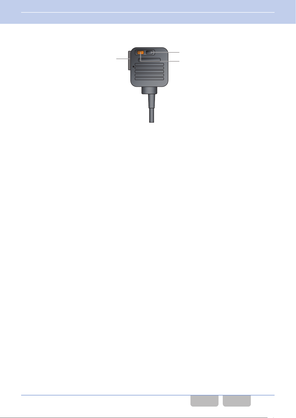
1
3
2
1 FUNCTIONS AND PANEL LAYOUT
1.2 NX-5700/ NX-5800/ NX-5900
External Microphone (KMC-25)
Figure 1-6 KMC-25
PTT Switch
A
Pressing the PTT switch allows transmitting.
PF 1 Key
B
The preassigned function will be activated or will be
changed to the active state.
PF 2 Key
C
The preassigned function will be activated or will be
changed to the active state.
Common FUNC (K, F)/Ver 2.20 8
CONTENTS INDEX
Page 40
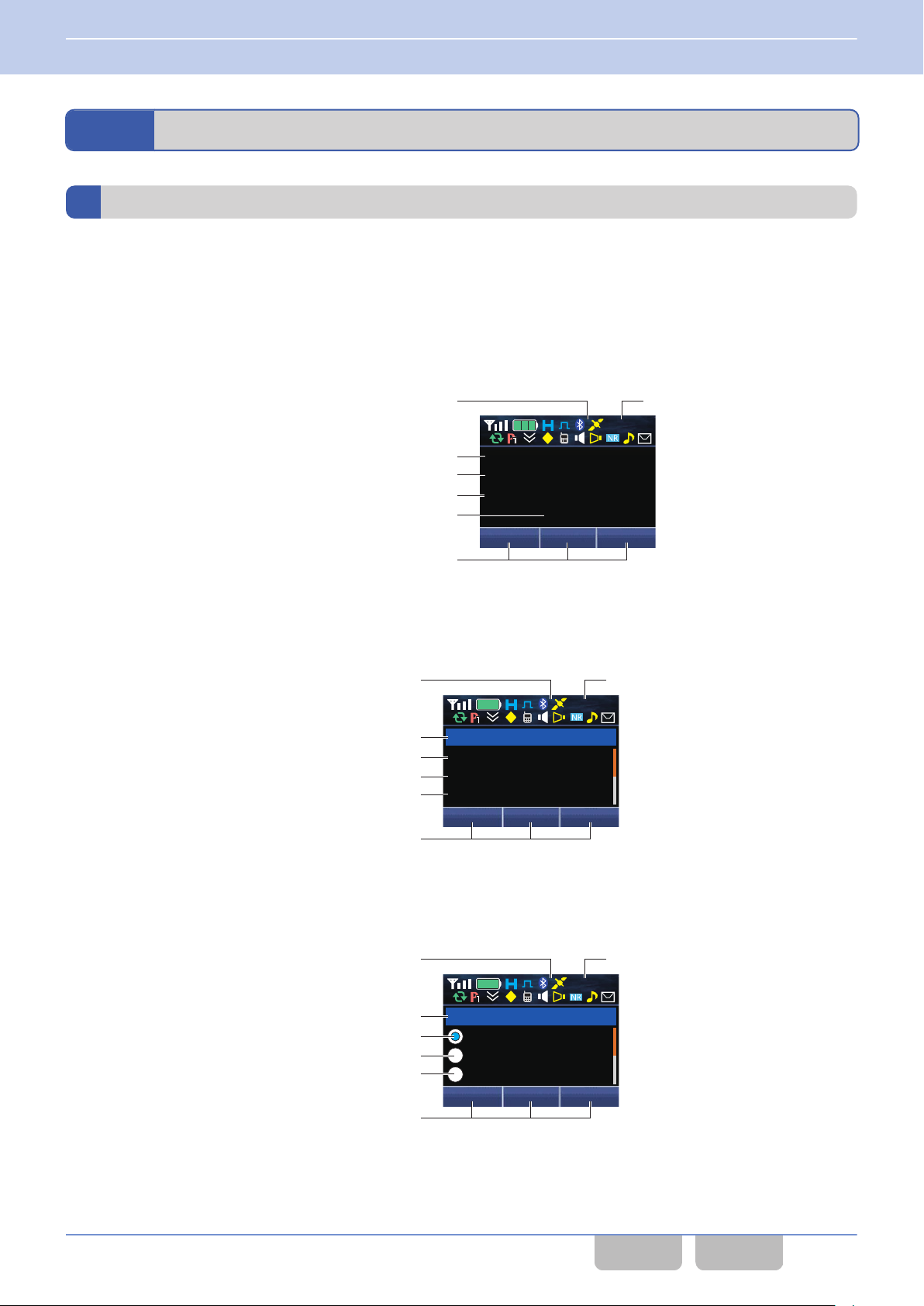
XXX XXX XXX
XXXXX
XXXXX
XXXXX
XXXXX
12 : 34
A
M
Icon
Sub Display (6 characters)
Main LCD (14 characters)
Key Guide (6 characters)
Cloc
k
Supplementary Field 1 (18 characters)
Supplementary Field 2 (18 characters)
XXXXX
XXXXX
XXXXX
XXXXX
XXX XXX XXX
12 : 34
A
M
Icon
Title (18 characters)
Line 2 (18 characters)
Key Guide (6 characters)
Cloc
k
Line 1 (18 characters)
Line 3 (18 characters)
XXXXX
XXXXX
XXXXX
XXX XXX XXX
XXXXX
12 : 34
A
M
Icon
Title (18 characters)
Line 2 (16 characters)
Key Guide (6 characters)
Cloc
k
Line 1 (16 characters)
Line 3 (16 characters)
1 FUNCTIONS AND PANEL LAYOUT
1.3 About LCD
1.3
About LCD
LCD
The LCD of the transceiver is as follows. The contents that appear on the LCD varies depending on the transceiver’s status.
Portable
Basic Frame
0
frame is used to display the name, such as the channel name. Various icons indicating the transceiver’s status appear
This
in the icon display area.
Function Mode Frame 1
0
This frame is used to display the Function Mode, such as Individual Call Mode and Status Mode. The number, such as
the list number or channel number, appears at the right end of the title line.
Function Mode Frame 2
0
frame is used to display the Function Mode, such as Status Mode. The number, such as the list number or channel
This
number, appears at the right end of the title line. The icon can be displayed at the right side of each line.
Common FUNC (K, F)/Ver 2.20 9
CONTENTS INDEX
Page 41
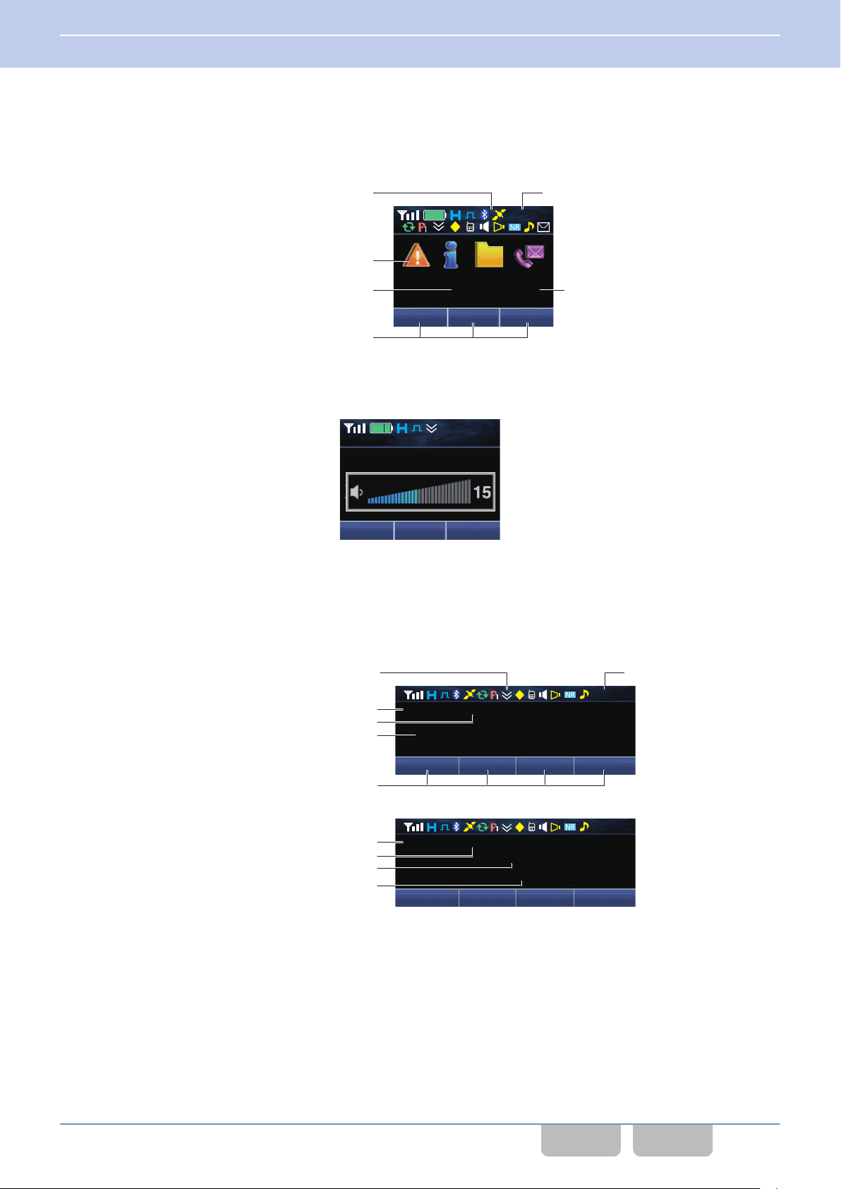
12 : 34
A
M
XXXXX XX
XXX XXX XXX
Icon
Category Icon
Key Guide (6 characters)
Clock
Category Name (18 characters) List Number
Menu
XXXXX
XXXXX
XXXXX
XXXXX
12 : 34
A
M
Zone
+
12 : 34
A
M
XXX XXX XXX XXX
XXXXXX XXXXX
XXXXX
12 : 34
A
M
XXX XXX XXX XXX
XXXXXX XXXXX
XXXXXXXXXXXXXX
XXXXXXXXXXXXXXXXXX
Icon
Sub Display (6 characters)
Main LCD (14 characters)
Key Guide (6 characters)
Clock
Supplementary Field 1 (18 characters)
Sub Display (6 characters)
Main LCD (14 characters)
Supplementary Field 1 (18 characters)
Supplementary Field 2 (18 characters)
1 FUNCTIONS AND PANEL LAYOUT
1.3 About LCD
Category Icon Frame
0
This frame is used to display the Menu Category in Icon Mode. Displays vary depending on the configuration in Menu
Icon Size. The following screens are display examples if Menu Icon Size is configured “Large”. (Refer to Using Menu
Mode.)
Popup Display
0
The popup appears when the adjustment of the volume level or the operation of Key Lock occurs.
Mobile (KCH-19 (Basic Panel))
Basic Frame
0
frame is used to display the name, such as the channel name. Various icons indicating the transceiver’s status appear
This
in the icon display area.
Common FUNC (K, F)/Ver 2.20 10
CONTENTS INDEX
Page 42
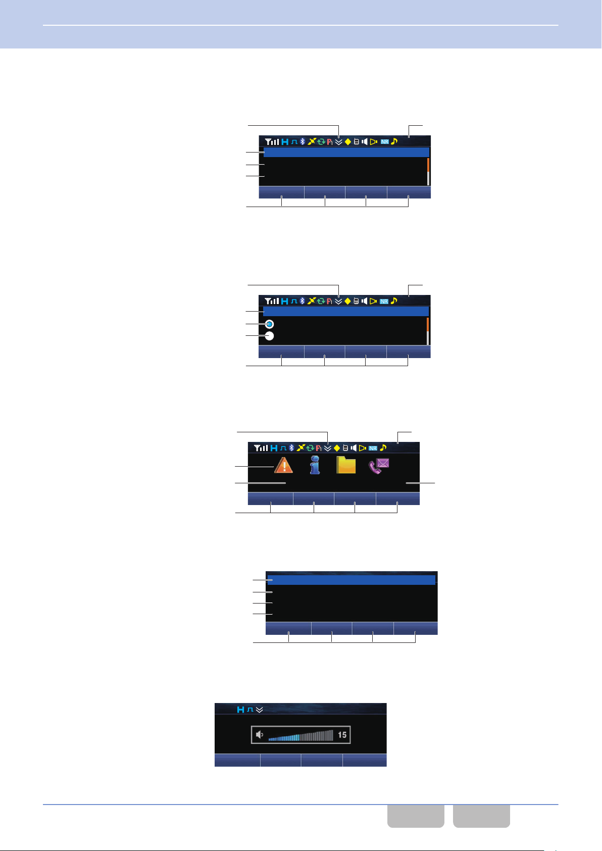
12 : 34
A
M
XXX XXX XXX XXX
XXXXXX
XXXXXXXXXXXXXX
XXXXXXXXXXXXXX
Icon
Title (32 characters)
Line 1 (24 characters)
Key Guide (6 characters)
Clock
Line 2 (24 characters)
12 : 34
A
M
XXX XXX XXX XXX
XXXXXX
XXXXXXXXXXXXXX
XXXXXXXXXXXXXX
Icon
Title (32 characters)
Line 1 (22 characters)
Key Guide (6 characters)
Clock
Line 2 (22 characters)
12 : 34
A
M
XXX XXX XXX XXX
XXXXXXXXXXXXXX XX
Icon
Category Icon
Category Name (18 characters) List Numbe
r
Key Guide (6 characters)
Clock
XXX XXX XXX XXX
XXXXXX
XXXXXXXXXXXXXX
XXXXXXXXXXXXXX
XXXXXXXXXXXXXX
Title (32 characters)
Key Guide (6 characters)
Line 1 (32 characters)
Line 2 (32 characters)
Line 3 (32 characters)
12 : 34
A
M
Menu SQ_Off Zone
-
Zone
+
XXXXXX XXXXX
XXXXX
1 FUNCTIONS AND PANEL LAYOUT
1.3 About LCD
Function Mode Frame 1
0
This frame is used to display the Function Mode, such as Individual Call Mode and Status Mode. The number, such as
the list number or channel number, appears at the right end of the title line.
Function Mode Frame 2
0
frame is used to display the Function Mode, such as Status Mode. The number, such as the list number or channel
This
number, appears at the right end of the title line. The icon can be displayed at the right side of each line.
Category Icon Frame
0
This frame is used to display the Menu Category in Icon Mode.
Message Frame
0
This frame is used to display the message, such as the Short Message.
Popup Display
0
The popup appears when the adjustment of the volume level or the operation of Key Lock occurs.
Common FUNC (K, F)/Ver 2.20 11
CONTENTS INDEX
Page 43
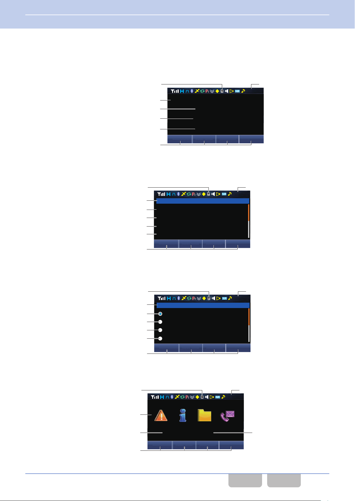
12 : 34
A
M
XXX XXX XXX XXX
XXXXXX
XXXXXXXXXXXXXX
XXXXXXXXXXXXXXXX
XXXXXXXXXXXXXXXX
Icon
Sub Display (6 characters)
Main LCD (14 characters)
Key Guide (6 characters)
Clock
Supplementary Field 1 (18 characters)
Supplementary Field 2 (18 characters)
12 : 34
A
M
XXX XXX XXX XXX
XXXXXXXXXXXXXXXXXXXXXXXXXXXXXX
XXXXXXXXXXXXXXXXXXXXXXXXXX
XXXXXXXXXXXXXXXXXXXXXXXXXX
XXXXXXXXXXXXXXXXXXXXXXXXXX
XXXXXXXXXXXXXXXXXXXXXXXXXX
Icon
Clock
Title (32 characters)
Line 1 (22 characters)
Key Guide (6 characters)
Line 2 (22 characters)
Line 3 (22 characters)
Line 4 (22 characters)
12 : 34
A
M
XXX XXX XXX XXX
XXXXXXXXXXXXXXXXXXXXXXXXXXXXXX
XXXXXXXXXXXXXXXXXXXXXXXX
XXXXXXXXXXXXXXXXXXXXXXXX
XXXXXXXXXXXXXXXXXXXXXXXX
XXXXXXXXXXXXXXXXXXXXXXXX
Icon
Clock
Title (32 characters)
Line 1 (22 characters)
Key Guide (6 characters)
Line 2 (22 characters)
Line 3 (22 characters)
Line 4 (22 characters)
12 : 34
A
M
XXX XXX XXX XXX
XXXXXXXXXXXX XX
Icon
Clock
Category Icon
Category Name (18 characters) List Number
Key Guide (6 characters)
1 FUNCTIONS AND PANEL LAYOUT
1.3 About LCD
Mobile (KCH-20R (Featured Panel))
Basic Frame
0
frame is used to display the name, such as the channel name. Various icons indicating the transceiver’s status appear
This
in the icon display area.
Function Mode Frame 1
0
This frame is used to display the Function Mode, such as Individual Call Mode and Status Mode. The number, such as
the list number or channel number, appears at the right end of the title line.
Function Mode Frame 2
0
frame is used to display the Function Mode, such as Status Mode. The number, such as the list number or channel
This
number, appears at the right end of the title line. The icon can be displayed at the right side of each line.
Category Icon Frame
0
This frame is used to display the Menu Category in Icon Mode.
Common FUNC (K, F)/Ver 2.20 12
CONTENTS INDEX
Page 44
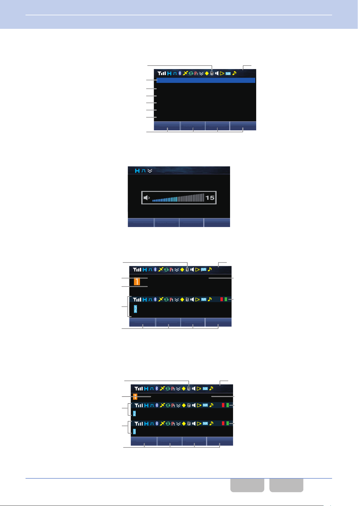
12 : 34
A
M
XXX XXX XXX XXX
XXXXXXXXXXXXXXXXXXXXXXXXXXX
XXXXXXXXXXXXXXXXXXXXXXXXXXXXXX
XXXXXXXXXXXXXXXXXXXXXXXXXXXXXX
XXXXXXXXXXXXXXXXXXXXXXXXXXXXXX
XXXXXXXXXXXXXXXXXXXXXXXXXXXXXX
XXXXXXXXXXXXXXXXXXXXXXXXXXXXXX
Icon
Clock
Title (32 characters)
Line 1 (32 characters)
Key Guide (6 characters)
Line 2 (32 characters)
Line 3 (32 characters)
Line 4 (32 characters)
Line 5 (32 characters)
XXXXXXXXXXXXXX
XXXXX
XXXXXXXXXXXXXXXXXXXX
12 : 34
A
M
XXX XXX XXX XXX
12 : 34
A
M
NR
XXXXXXXXXXXXXX XXXXXX
XXX XXX XXX XXX
XXXXXXXXXXXXXXXXX
XXXXXXXXXXXXXX XXXXXX
XXXXXXXXXXXXXX XXXXXX
XXXXXXXXXXXXXXXXX
Icon (RF Deck 1)
Clock (Multi RF Deck)
Main LCD (RF Deck 1) (14 characters)
Supplementary Field 1 (18 characters)
Sub Display (RF Deck 1) (6 characters)
Virtual LED (RF Deck 2)
Key Guide (6 characters)
RF Deck 2 Display Field
12 : 34
A
M
XXX XXX XXX XXX
XXXXXXXXXXXXXX XXXXXX
XXXXXXXXXXXXXX XXXXXX
XXXXXXXXXXXXXX XXXXXX
Icon (RF Deck 1)
Sub Display (RF Deck 1) (6 characters)
Clock (Multi RF Deck)
Virtual LED (RF Deck 2)
Virtual LED (RF Deck 3)
RF Deck 2 Display Field
RF Deck 3 Display Field
Main LCD (RF Deck 1) (14 characters)
Key Guide (6 characters)
1 FUNCTIONS AND PANEL LAYOUT
1.3 About LCD
Message Frame
0
This frame is used to display the message, such as the Short Message.
Popup Display
0
The popup appears when the adjustment of the volume level or the operation of Key Lock occurs.
Dual Frame
0
This frame is used to display the channel name in the Dual RF Deck structure. This frame appears when Multi RF Deck
View is On.
Other than the clock display and virtual LED, the display specifications of RF Deck 1 and RF Deck 2 are the same.
Triple Frame
0
frame is used to display the channel name in the Triple RF Deck structure. This frame appears when Multi RF Deck
This
View is On.
Other than the clock display and virtual LED, the display specifications of RF Deck 1, RF Deck 2 and RF Deck 3 are the
same.
Common FUNC (K, F)/Ver 2.20 13
CONTENTS INDEX
Page 45
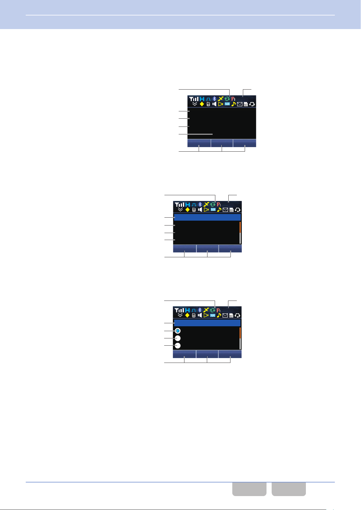
XXX XXX XXX
XXXXX
XXXXX
XXXXX
XXXXX
12 : 34
A
M
Icon
Sub Display (6 characters)
Main LCD (14 characters)
Key Guide (6 characters)
Cloc
k
Supplementary Field 1 (18 characters)
Supplementary Field 2 (18 characters)
XXXXX
XXXXX
XXXXX
XXXXX
XXX XXX XXX
12 : 34
A
M
Icon
Title (18 characters)
Line 2 (18 characters)
Key Guide (6 characters)
Cloc
k
Line 1 (18 characters)
Line 3 (18 characters)
XXXXX
XXXXX
XXXXX
XXX XXX XXX
XXXXX
12 : 34
A
M
Icon
Title (18 characters)
Line 2 (16 characters)
Key Guide (6 characters)
Clock
Line 1 (16 characters)
Line 3 (16 characters)
1 FUNCTIONS AND PANEL LAYOUT
1.3 About LCD
Mobile (KCH-21R (Handheld Control Head))
Basic Frame
0
frame is used to display the name, such as the channel name. Various icons indicating the transceiver’s status appear
This
in the icon display area.
Function Mode Frame 1
0
frame is used to display the Function Mode, such as Individual Call Mode and Status Mode. The number, such as the
This
list number or channel number, appears at the right end of the title line.
Function Mode Frame 2
0
This frame is used to display the Function Mode, such as Status Mode. The number, such as the list number or channel
number, appears at the right end of the title line. The icon can be displayed at the right side of each line.
Common FUNC (K, F)/Ver 2.20 14
CONTENTS INDEX
Page 46
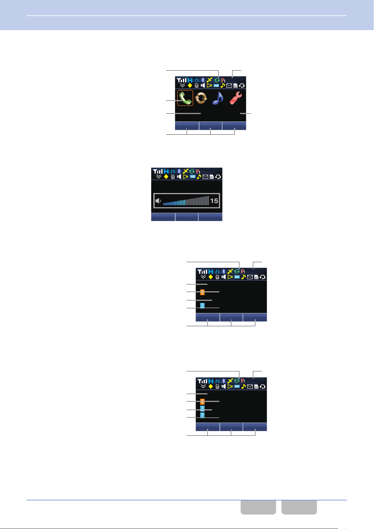
12 : 34
A
M
XXXXX XX
XXX XXX XXX
Icon
Category Icon
Key Guide (6 characters)
Clock
Category Name (14 characters) List Number
XXXXX
XXXXX
XXXXX
XXXXX
XXX XXX XXX
12 : 34
A
M
XXX XXX XXX
XXXXX
XXXXXXXXXX
XXXXX
XXXXXXXXXX
12 : 34
A
M
Icon (RF Deck 1)
Main LCD (RF Deck 1) (14 characters)
Main LCD (RF Deck 2) (14 characters)
Key Guide (6 characters)
Clock
RF Deck 1 Display Field (18 characters)
RF Deck 2 Display Field (18 characters)
XXX XXX XXX
XXXXX
XXXXXXXXXX
XXXXX
XXXXXXXXXX
12 : 34
A
M
Icon (RF Deck 1)
Main LCD (RF Deck 1) (14 characters)
Main LCD (RF Deck 2) (18 characters)
Key Guide (6 characters)
Clock
RF Deck 1 Display Field (18 characters)
RF Deck 2 Display Field (18 characters)
1 FUNCTIONS AND PANEL LAYOUT
1.3 About LCD
Category Icon Frame
0
This frame is used to display the Menu Category in Icon Mode.
Popup Display
0
The popup appears when the adjustment of the volume level or the operation of Key Lock occurs.
Dual Frame
0
This frame is used to display the channel name in the Dual RF Deck structure. This frame appears when Multi RF Deck
View is On.
Triple Frame
0
This frame is used to display the channel name in the Triple RF Deck structure. This frame appears when Multi RF Deck
View is On.
Other than the clock display and virtual LED, the display specifications of RF Deck 1, RF Deck 2 and RF Deck 3 are the
same.
Common FUNC (K, F)/Ver 2.20 15
CONTENTS INDEX
Page 47
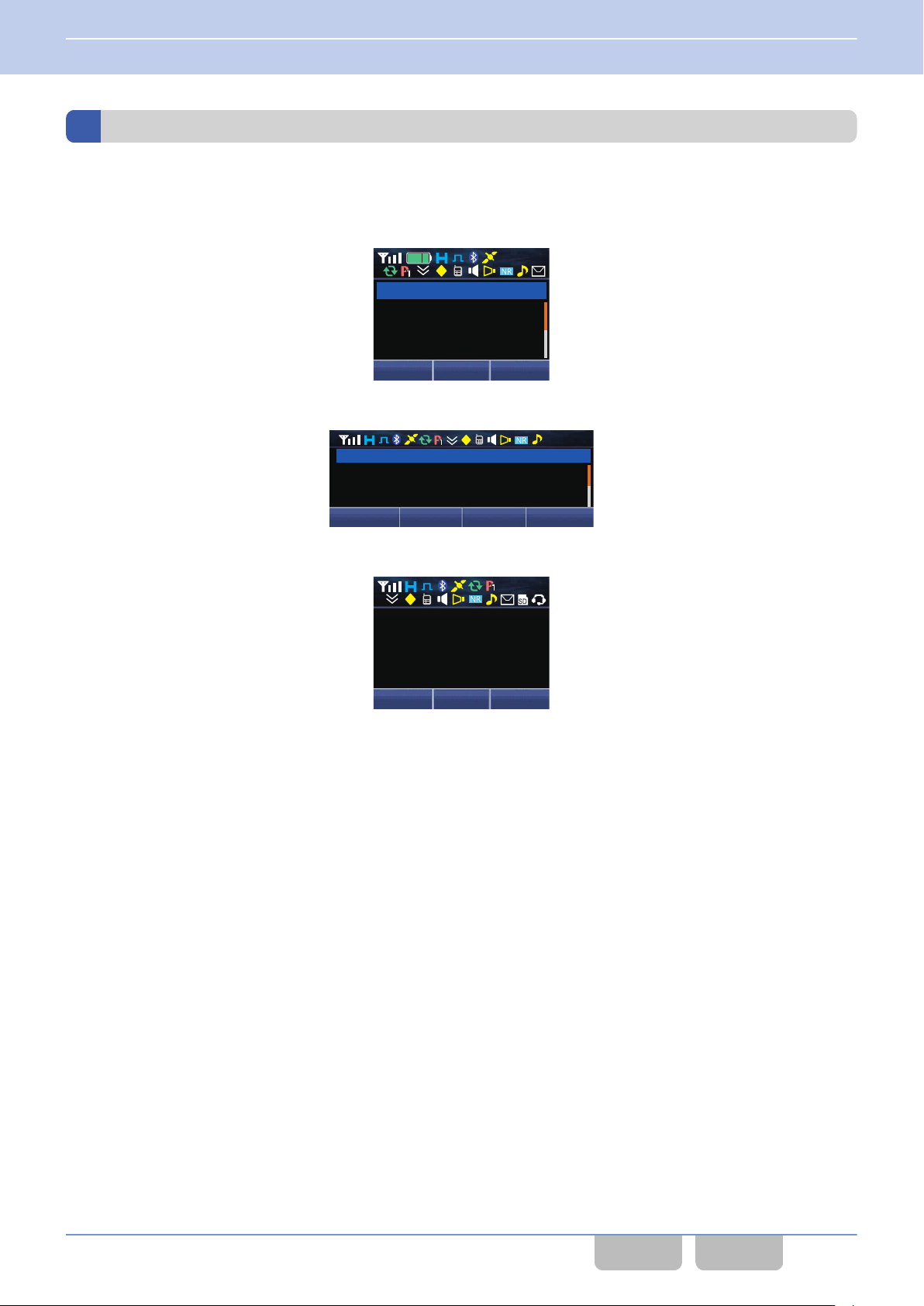
XXXXX
XXXXX
XXXXX
XXXXX
XXX XXX XXX
12 : 34
A
M
12 : 34
A
M
XXX XXX XXX XXX
XXXXXX
XXXXXXXXXXXXXX
XXXXXXXXXXXXXX
XXX XXX XXX
XXXXX
XXXXX
XXXXX
XXXXX
12 : 34
A
M
1 FUNCTIONS AND PANEL LAYOUT
1.3 About LCD
Icons
Various icons indicating the transceiver’s status appear in the icon display area when a channel name is displayed. Refer
to “The Icons on the LCD” for details of each icon.
Portable
0
Mobile (KCH-19 (Basic Panel)/ KCH-20R (Featured Panel))
0
Mobile (KCH-21R (Handheld Control Head))
0
Common FUNC (K, F)/Ver 2.20 16
CONTENTS INDEX
Page 48
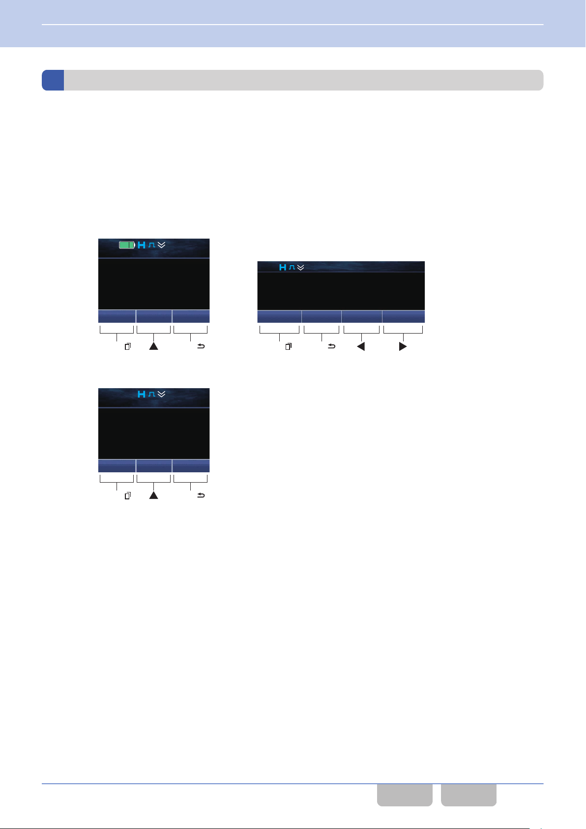
Menu IndcalZone
+
Zone 1
Channel 1
12 : 34
A
M
Portable: Mobile (KCH-19 (Basic Panel)/ KCH-20R (Featured Panel):
12 : 34
A
M
Menu SQ_Off Zone
-
Zone
+
Zone 1
Channel 1
Menu ([
])
[ ]
Menu ([
])
[ ] [ ]
Back
([
])
Back
([
])
Menu IndcalZone
+
Zone 1
Channel 1
12 : 34
A
M
Mobile (KCH-21R (Handheld Control Head)):
Menu ([
])
[ ]
Back
([
])
1 FUNCTIONS AND PANEL LAYOUT
1.3 About LCD
Key Guide
The key guide is displayed at the bottom of the LCD.
For Portable, the key guide displays the functions that function when the Menu ([Q]), [G] or Back ([O]) key is pressed.
Mobile, the key guide displays the functions that function when the Menu ([Q]), Back ([O]) or [E], [F] key is pressed.
For
The text that appears on the display varies depending on the transceiver’s status.
PF Key
0
Functions assigned to each key will appear while the channel name appears. (Refer to Available Functions for the PF
Keys.)
Common FUNC (K, F)/Ver 2.20 17
CONTENTS INDEX
Page 49
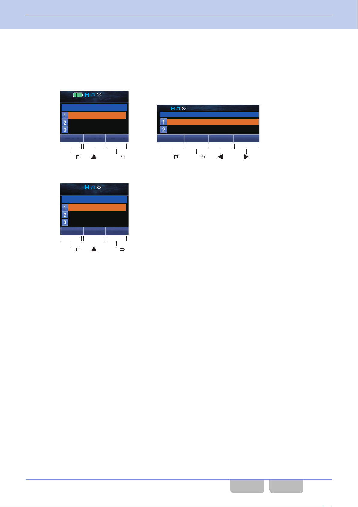
Portable: Mobile (KCH-19 (Basic Panel)/ KCH-20R (Featured Panel):
A
M
Next Back
Menu ([
])
[ ]
Menu ([
])
[ ] [ ]
Next
Call 1
12 : 34
A
M
Individual
Group
Status
Back
12 : 34
Call 1
Individual
Group
Back
([
])
Back
([
])
Mobile (KCH-21R (Handheld Control Head)):
Menu ([
])
[ ]
Next
Call 1
12 : 34
A
M
Individual
Group
Status
Back
Back
([
])
1 FUNCTIONS AND PANEL LAYOUT
1.3 About LCD
Function Mode
0
Functions
that can be used in each mode appear while the transceiver is in Function Mode, such as Selcall Mode, Status
Mode and Stack Mode. However, the key guide for the Up key does not appear if the function which is used to select the
list or code is assigned to the [G] or [H] key.
Common FUNC (K, F)/Ver 2.20 18
CONTENTS INDEX
Page 50
1 FUNCTIONS AND PANEL LAYOUT
1.3 About LCD
The following are key guides that appear while the transceiver is in Function Mode. (Refer to Function Mode.)
Table 1-1 Key Guide (Function Mode)
Key Guide Operation
OK Determines the data of the entered characters, code, or list.
Select Determines the data of the selected characters, code, or list.
Delete Deletes the data of the selected characters, code, or list.
Confirm Authenticates the entered password.
Exit Aborts the Function Mode.
Next Proceeds to the next step.
Back Goes back to the previous step.
Prev (Mobile only) Restores the previous display.
Pause Stops recording.
Conn Enters the state to confirm connection with the device.
Discon Enters the state to confirm disconnection with the device.
Call Initiates the call.
Send Sends the data.
Page Initiates the Paging Call.
Cancel Cancels the operation.
K
Disp (Mobile only) Switches the display.
Disp L (Mobile only) Switches the display.
K (Mobile only) Selects a category.
L (Mobile only) Selects a category.
I (Mobile only) Plays back the audio data from the beginning.
J (Mobile only) Plays back the next audio data from the beginning.
List+ Selects list data.
List- Selects list data.
View Switches to the Short Message View display.
Note
0
The key guide which appears while the transceiver is in Function Mode is only for the functions that can be activated.
0
Guide for a function assigned to and activated by pressing and holding a PF key appears only if no function is assigned
Key
to the same key.
Example 1) “KeyLck” appears as Key Guide in the following case: Function = None, Hold = Key Lock
Example 2) “Light” appears as Key Guide in the following case: Function = Backlight, Hold = Key Lock
Common FUNC (K, F)/Ver 2.20 19
CONTENTS INDEX
Page 51
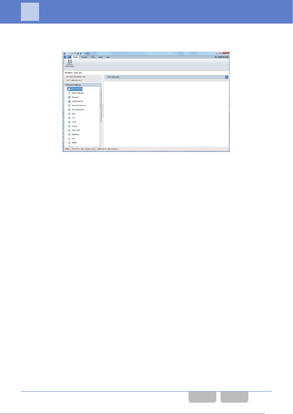
2 GETTING STARTED
2
When the transceiver is turned ON after the power source is attached to the transceiver, the transceiver starts up. To make
transceiver ready for use, the configuration data needs to be created using KPG-D1/ D1N and written to the transceiver.
the
GETTING STARTED
Figure 2-1 KPG-D1/ D1N Main Window
By using KPG-D1/ D1N, the zone and channel data needs to be configured and then the parameters for various functions
can be configured. Refer to the help texts for configuration methods.
Common FUNC (K, F)/Ver 2.20 20
CONTENTS INDEX
Page 52
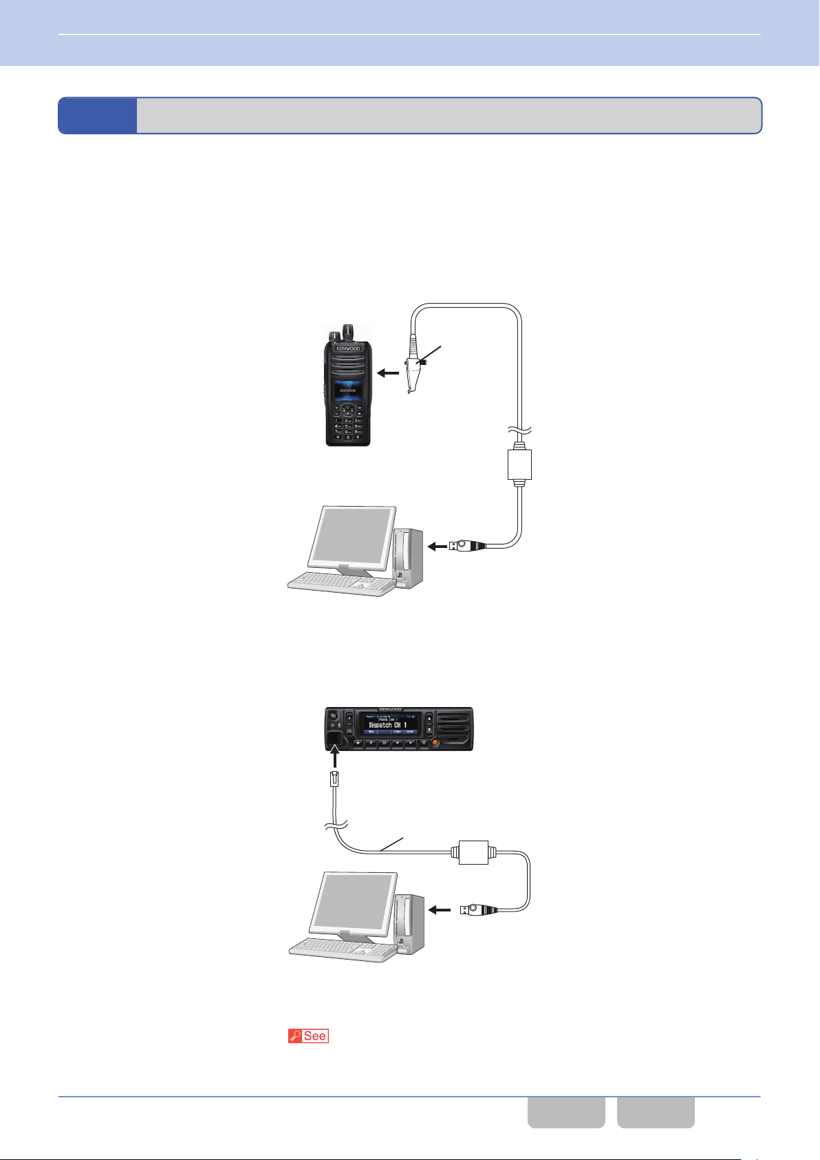
KPG-36U/
KPG-36X
To the
Universal Connector
To a USB Port
KPG-46U/ KPG-46X
To the Microphone Connector
To a USB Port
2 GETTING STARTED
2.1 Connecting the Transceiver to a PC
2.1
Connecting the Transceiver to a PC
To write the configuration data to or read the configuration data from the transceiver via serial communications by using a
programming cable, “Programming Cable” needs to be selected from Communication Method
of COM port. Also, the
transceiver and a PC with KPG-D1/ D1N installed need to be connected by using the programming cable.
Portable
The transceiver and a PC need to be connected by using the KPG-36U/ KPG-36X programming cable.
Refer to the figure below.
Mobile
The transceiver and a PC need to be connected by using the KPG-46U/ KPG-46X programming cable.
Refer to the figure below.
Configuration using KPG-D1/ D1N
Configuring Communication Method ( Setup > COM port)
Common FUNC (K, F)/Ver 2.20 21
CONTENTS INDEX
Page 53
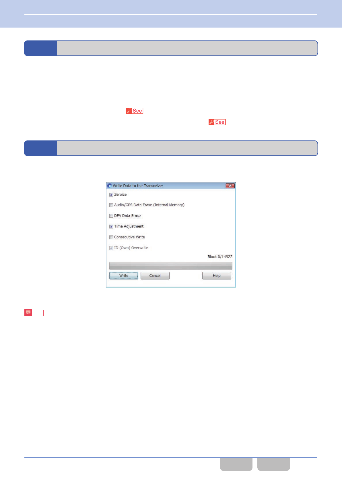
2 GETTING STARTED
2.2 Connecting the Transceiver to a PC by Bluetooth
2.2
To write the configuration data to the transceiver or to read the configuration data from the transceiver by using Bluetooth
communication, “Bluetooth SPP” needs to be selected from Communication Method of COM port and a Bluetoothcompatible device (the transceiver) to be written with the configuration data needs to be selected in Device List.
Connecting the Transceiver to a PC by Bluetooth
Configuration using KPG-D1/ D1N
0
Configuring Communication Method ( Setup > COM port)
0
Selecting a Bluetooth-compatible device (the transceiver) in Device List ( Setup > COM port > Bluetooth SPP)
2.3
Clicking the “Write” button in Program
of Write Data to the Transceiver enters FPU Programming Mode and starts writing the configuration data to the transceiver.
Writing the Configuration Data to the Transceiver
of KPG-D1/ D1N displays Write Data to the Transceiver. Clicking the “Write” button
Figure 2-2 Write Data to the Transceiver
Note
The transceiver behaves as follows according to the configuration in Write Data to the Transceiver:
0
Clicking on Zeroize and writing deletes the Encryption Key configuration in the SCM.
0
Clicking on Time Adjustment and
to “ADJUSTING THE TIME ON THE TRANSCEIVER” for the operations to manually adjust the time of the transceiver
after writing the configuration data.
0
Clicking on Audio/GPS Data Erase (Internal Memory) and writing deletes the audio data and GPS data stored on the
transceiver.
0
Clicking on DFA Data Erase and writing deletes the Direct Frequency Assignment information stored on the transceiver.
0
Clicking on Consecutive Write and writing does not close Write Data to the Transceiver even when the writing
completes, and various IDs can be changed and written in other transceiver.
0
Clicking on ID (Own) Overwrite and writing overwrites various ID data on the transceiver by the ID data configured by
KPG-D1/ D1N. Clicking off ID (Own) Overwrite and writing can write configuration data on the transceiver without
overwriting various IDs configured in the transceiver.
writing automatically configures the transceiver to the time configured in a PC. Refer
Common FUNC (K, F)/Ver 2.20 22
CONTENTS INDEX
Page 54
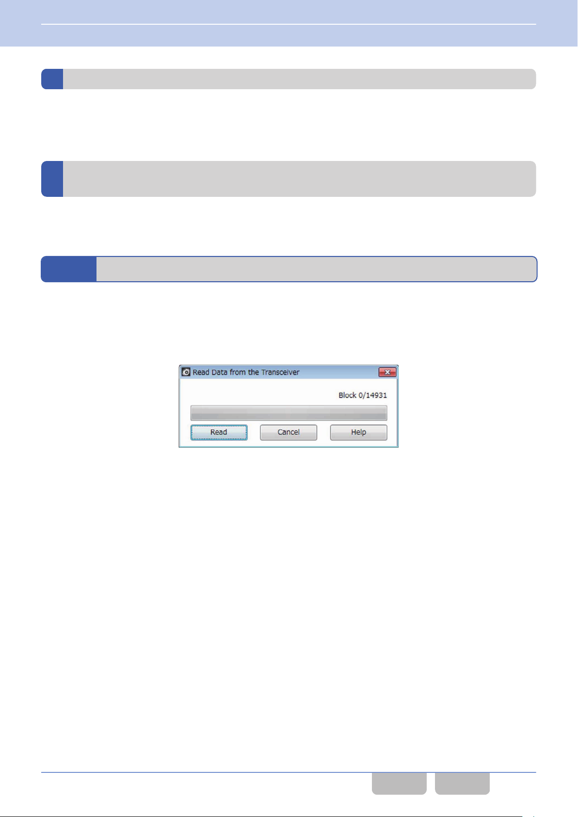
2 GETTING STARTED
2.3 Writing the Configuration Data to the Transceiver
Writing configuration data to multiple transceivers using Bluetooth communication
To write configuration data to multiple transceivers by using Bluetooth communication, click the “Multi Write (Bluetooth)”
button. A Bluetooth-compatible device (the transceiver) is detected in Write Data to Multiple Transceiver (Bluetooth),
and the configuration data can be written to the transceiver by Bluetooth communication.
About the writing of configuration data in a Multi RF Deck/ Multi Control Head
structure
Refer to “Configuring
the writing of configuration data in a Multi RF Deck/ Multi Control Head structure for Mobile.
2.4
To change the data configured in the transceiver, read the configuration data from the transceiver to KPG-D1/ D1N, and
then write the configuration data to the transceiver after the configuration data has been changed.
Clicking the “Read” button in Program of KPG-D1/ D1N displays Read Data from the Transceiver. Clicking the “Read”
button of Read Data from the Transceiver enters FPU Programming Mode and starts reading the configuration data to
the transceiver.
the FPU Data and Writing the FPU Data to Each RF Deck” in “Multi RF Deck/ Multi Control Head” for
Reading the Configuration Data from the Transceiver
Figure 2-3 Read Data from the Transceiver
Common FUNC (K, F)/Ver 2.20 23
CONTENTS INDEX
Page 55
2 GETTING STARTED
2.5 Embedding a Message in the Transceiver (Embedded Message)
2.5
Embedding a Message in the Transceiver (Embedded Message)
The message can be written to the transceiver as part of the configuration data by using KPG-D1/ D1N.
Embedded Message
Embedded Message can be used to store a maximum of 64 characters in the transceiver. The transceiver profile
information, such as the control number and the file name of the configuration data written in the transceiver, can be
embedded.
message can be written to the transceiver by using KPG-D1/ D1N. The message written in the transceiver is stored as
The
a part of the configuration data.
The embedded messages can be read from the transceiver by using KPG-D1/ D1N.
Configuration using KPG-D1/ D1N
Configuring Embedded Message (
Embedded Message with Password
Transceiver Settings > Embedded Message)
Embedded Message with Password can be used to store with a password a maximum of 64 alphanumeric characters
and symbols in the transceiver.
The transceiver profile information, such as the control number and the file name of configuration data written in the
transceiver, can be embedded with a password.
The message and the password can be written to the transceiver by using KPG-D1/ D1N. The Embedded Message with
Password is stored in the transceiver as independent data from the configuration data.
password needs to be entered to write a message to the transceiver written with a password. The message cannot be
The
written to the transceiver unless the correct password is entered.
The embedded messages can be read from the transceiver by using KPG-D1/ D1N.
Configuration using KPG-D1/ D1N
Configuring Embedded Message with Password
(
Transceiver Settings > Embedded Message with Password)
Common FUNC (K, F)/Ver 2.20 24
CONTENTS INDEX
Page 56
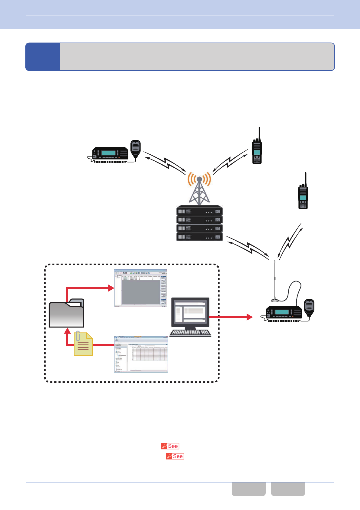
Base Station Transceiver
FPU
KPG-180AP
Read in
Configuration Data
Creation
Serial Transfer
Shared
Directory
NEXEDGE Repeater Site
or
P25 System
Subscriber Unit
Subscriber
Unit
Subscriber
Unit
2 GETTING STARTED
2.6 Writing Configuration Data Using Wireless Communication (OTAP)
2.6
Writing Configuration Data Using Wireless Communication (OTAP)
OTAP (Over-The-Air Programming) is the function to write configuration data to the transceiver using wireless
communications.
base station.
OTAP can be used in a communication system which supports NEXEDGE or P25 digital communication (an NXDN
Conventional system, an NXDN Trunking system, or a P25 Conventional system).
To use this function, the PC application software, OTAP Manager (KPG-180AP) is required to manage configuration data
of KPG-D1/ D1N and transmit the configuration data to each subscriber unit via the base station transceiver.
This function enables configuration data for the transceiver to be updated by remotely controlling from the
Figure 2-4 Example of the System Structure
The
transceiver for which OTAP is enabled can be used in a system where OTAP is incorporated. The subscriber unit can
write the received configuration data into the unit and enable the configuration data. The base station transceiver can send
the configuration data to the subscriber unit according to the request from OTAP Manager.
Refer to OTAP MANAGER (KPG-180AP) Basic Operations supplied with KPG-180AP for the details of this function.
Configuration using KPG-D1/ D1N
0
Configuring P25 OTAP to be enabled or disabled (
0
Configuring NXDN OTAP to
be enabled or disabled (
Model > Product Information > Feature Selection > P25)
Model
> Product Information > Feature Selection > NXDN)
Common FUNC (K, F)/Ver 2.20 25
CONTENTS INDEX
Page 57
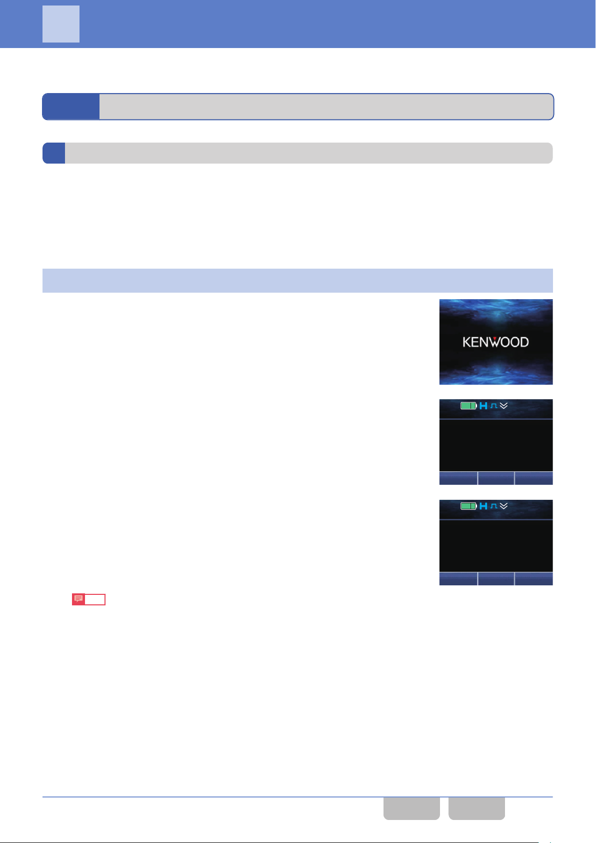
Zone
+
Zone 1
Truck 8649
12 : 34
A
M
Menu Zone
+
Zone 1
Channel 1
12 : 34
A
M
3 BASIC OPERATIONS
3
BASIC OPERATIONS
3.1
Turning the Transceiver ON/ OFF
Turning the Transceiver ON
For Portable, rotating the Power switch clockwise causes the transceiver to be turned ON.
For Mobile, pressing the Power switch
linking to the status of the Ignition Sense port of a vehicle. (Refer to Turning the Transceiver ON or OFF According to the
State of the Ignition Sense Port (Ignition Sense).)
If the data is written to the transceiver and the password is not configured
0
Turn the Transceiver ON.
1
A Power-on Tone A (1 beep) sounds from the transceiver, and then an
animated logo appears for 500 ms.
If Custom Start-up Screen is configured, a Power-on Tone A (1 beep)
sounds from the transceiver when the transceiver is turned ON and the
bitmapped image configured for the transceiver appears for 2 sec. (Refer
to Displaying a Bitmap Image When the Transceiver is Turned ON (Custom
Start-up Screen).)
causes the transceiver to be turned ON. Also, the transceiver can be turned ON by
If Power-on Text is configured, the Power-on Text appears for 2 sec after
“SELF TESTING” appears. (Refer to Power-on Text.)
The transceiver enters User Mode, and then the channel name appears.
Note
The animated logo appears only if Custom-Start-up Screen
configured.
is not
Common FUNC (K, F)/Ver 2.20 26
CONTENTS INDEX
Page 58
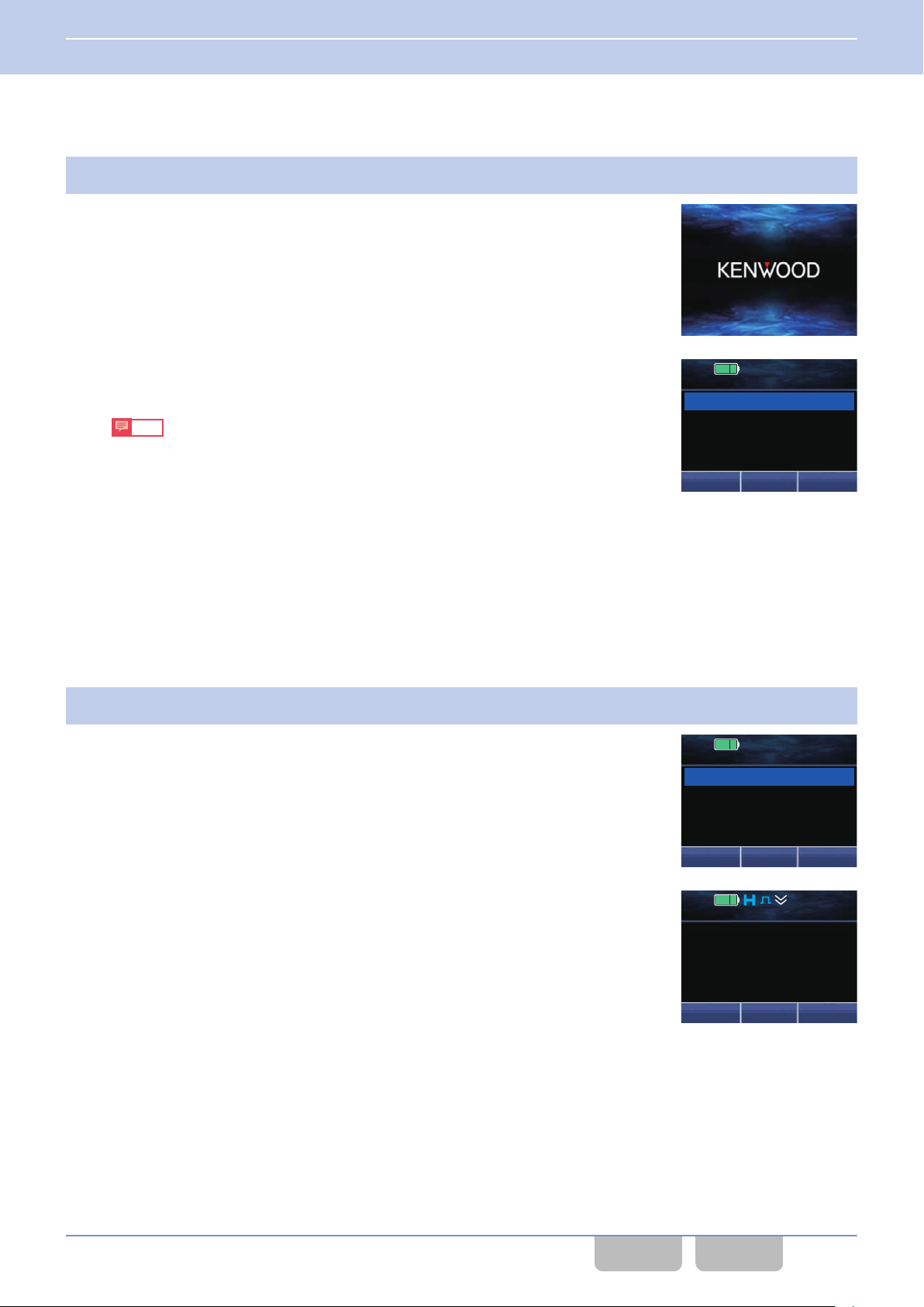
12 : 34
A
M
Password
Input Password
12 : 34
A
M
Password
0123
DeleteConfrm
Menu Zone
+
Zone 1
Channel 1
12 : 34
A
M
3 BASIC OPERATIONS
3.1 Turning the Transceiver ON/ OFF
If the data is written to the transceiver and the transceiver’s password is configured
0
Turn the Transceiver ON.
1
A Power-on Tone A (1 beep) sounds from the transceiver, and then an
animated logo appears for 500 ms.
If Custom Start-up Screen is configured, a Power-on Tone A (1 beep)
sounds from the transceiver when the transceiver is turned ON and the
bitmapped image configured for the transceiver appears for 2 sec. (Refer
to Displaying
a Bitmap Image When the Transceiver is Turned ON (Custom
Start-up Screen).)
“Password” appears after “SELF TESTING” appears. (Refer to Password
for Transceiver Operation (Transceiver Password).)
Note
0
The animated logo appears only if Custom-Start-up Screen is not
configured.
0
In the following cases, if the transceiver is turned ON, the transceiver
enters Transceiver Password Mode:
0
If Transceiver Password is
configured, “Transceiver Password”
is not assigned to any of the PF keys, and “Transceiver Password”
is not configured in Menu Mode
0
When “Transceiver Password” is assigned to one of the PF keys,
or when “Transceiver Password” is configured for Menu Mode, if
the transceiver is turned OFF while the transceiver is in
Transceiver Password Mode
Enter a password.
2
Refer to “Entering or Deleting a Code” for entry methods.
the correct password is entered, a Password Authorization Tone (2
When
beeps) sounds from the transceiver, and then the password protection of
the transceiver is disabled.
If Power-on Text is configured, the Power-on Text appears for 2 sec.
(Refer to Power-on Text.)
The transceiver enters User Mode, and then the channel name appears.
Common FUNC (K, F)/Ver 2.20 27
CONTENTS INDEX
Page 59
3 BASIC OPERATIONS
3.1 Turning the Transceiver ON/ OFF
Note
0
If the firmware is not written to the transceiver correctly, the transceiver will enter Firmware Programming Mode. In this
case, write the firmware to the transceiver again.
0
“UNPROGRAM”
appears on the main display if no data is written to the transceiver. In this case, data needs to be written
to the transceiver by using KPG-D1/ D1N.
0
In a Multi RF Deck system, pressing the Power switch for 1000 ms causes the transceiver to be turned ON.
0
The Power-on Tone A tone when the transceiver is turned ON can be created as desired using KPG-D1/ D1N.
Turning the Transceiver OFF
For Portable, rotate the Power switch counterclockwise until it clicks to turn the transceiver OFF.
For Mobile, pressing the Power
the transceiver can be turned OFF according to the status of the vehicle engine, either switched On or Off. (Refer to Turning
the Transceiver ON or OFF According to the State of the Ignition Sense Port (Ignition Sense).)
Also, for Mobile, pressing the Power switch for more than 5 sec forcibly turns the transceiver OFF. If the Power switch is
pressed while the transceiver is turned ON, or if an error occurs from when the Ignition Sense port goes low level until the
transceiver is turned OFF, or if a function in a P25 Trunking system, such as De-Registration, is functioning waiting for the
transmission or response of Suspended Power-off and Power-off Status, the transceiver may actually be in the ON state
even if nothing appears on the display. To turn the transceiver OFF immediately in this state, pressing the Power switch for
more than 5 sec forcibly turns the transceiver OFF. If “Ignition Only” is configured in Ignition Sense Type, the Ignition Sense
port needs to be at high level in order to turn the transceiver ON next time. In this case, the transceiver cannot be turned
ON by pressing the Power switch.
switch while the transceiver is turned ON causes the transceiver to be turned OFF. Also,
Power Switch Status Memory
Supported Models: Mobile
Power
Switch Status Memory is the function to configure whether to store the Power switch status (ON or OFF) when the
power source is disconnected from the transceiver.
Whether to turn the transceiver ON when the power source is connected to the transceiver depends as below on the
configuration in Power Switch Status Memory:
Table 3-1 Power Switch Status Memory
Configuration Description
Enables the capability to retain the ON- or OFF-state of the Power
switch. By disconnecting the power
source while the transceiver Power switch is in the ON state and then by reconnecting the power source,
Enabled
the transceiver is turned ON and starts up. Even if the power source is reconnected after the power
source is disconnected while the transceiver Power switch is in the OFF state, the transceiver remains
turned OFF. In this case, the transceiver does not start up unless the Power switch is pressed.
Disables the capability to retain the ON- or OFF-state of the Power switch. Regardless of the previous
Disabled
ON- or OFF-state of the Power switch, the transceiver power is turned ON by connecting the power
source to the transceiver.
Configuration using KPG-D1/ D1N
Configuring Power Switch Status Memory ( Transceiver Settings > Optional Features > Optional Features 1 >
Others)
Common FUNC (K, F)/Ver 2.20 28
CONTENTS INDEX
Page 60
3 BASIC OPERATIONS
3.2 Adjusting the Volume Level
3.2
Adjusting the Volume Level
Portable
Rotating the Volume control clockwise increases the volume level from the speaker, and rotating the Volume control
counterclockwise decreases the volume level from the speaker.
Mobile
Pressing the Volume Up key increases the volume level in steps of 1. Pressing the Volume Down key decreases the
volume level in steps of 1. KCH-20R (Featured Panel) is operated by using the Volume control just as Portable.
If “Volume Up (Continuous)” or “Volume Down (Continuous)” is assigned to the Volume Up or Volume Down key, the
volume level is increased or decreased continuously every 100 ms by pressing and holding the Volume Up or Volume
Down key.
3.3
The following functions can be assigned to each key of the transceiver using KPG-D1/ D1N. Pressing a key to which a
function is assigned can activate the assigned function or place the transceiver in various Function Modes. (Refer to
Available Functions for the PF Keys.)
Following are the configuration examples for each key of the transceiver.
Using Function Keys
Table 3-2 Configuration Examples for Keys
Key Function 2nd Function Hold Hold Delay
Home ([T])
Back ([O])
AUX Function None None 1.0
A function can be assigned to Function, 2nd Function and Hold of each key on the transceiver.
Function
0
The function is activated by pressing a key.
In the configuration example above, pressing the Home
to each key.
If a key to which Function is assigned is pressed, the transceiver waits for a function assigned to 2nd Function to be
activated.
2nd Function
0
The function is activated by pressing a key to which the function is assigned to 2nd Function after the Function key is
pressed.
In the configuration example above, pressing the Back ([O]) key after the AUX key is pressed activates the Autodial
function.
Hold
0
The function is activated by pressing and holding a key for the length of time configured for Hold Delay.
In the configuration example above, pressing and holding the Home ([T]) key for 3 sec activates the Home Channel
Select function.
Home Channel None Home Channel Select 3.0
Key Lock Autodial None 1.0
([T]), Back ([O]), or AUX key activates the function assigned
Note
The two functions, Primary and Secondary, can be assigned to each key on the transceiver. Which function is used can
be configured for each zone or channel.
Configuration using KPG-D1/ D1N
Assigning functions to the PF
keys on the transceiver (
Common FUNC (K, F)/Ver 2.20 29
Transceiver Settings > Key Assignment)
CONTENTS INDEX
Page 61

3 BASIC OPERATIONS
3.3 Using Function Keys
Mode Reset Timer
Mode Reset Timer
is the timer for canceling the standby status of further key entry in Function Mode, and for canceling the
function activation status of 2nd Function. By using this function, Function Mode does not need to be disabled manually.
The function also helps by canceling the Function Mode automatically so as not to remain in Function Mode for too long a
time.
The transceiver has some special Function Modes. When the transceiver enters one of these modes, a preprogrammed
display appears on the main display and sub-display and the Mode Reset Timer starts counting down the time. If no key
is pressed before the amount of time configured in Mode Reset Timer expires, the transceiver returns to the previous mode.
If a Function key is pressed, the transceiver waits for a function configured for 2nd Function to be activated, and then Mode
Reset Timer starts counting down. If no key is pressed before the amount of time configured in Mode Reset Timer expires,
the transceiver cancels waiting for the function to be activated. Mode Reset Timer can be extended by key operation.
Mode Reset Timer is used for the following Function Modes:
Table 3-3 Objective Function Modes for Mode Reset Timer
2-tone Mode
Activity Detection Mode
ANR Preset Mode
Audio Profile Mode
Auto Dimmer Mode
*1
*1
*1
*1
Autodial Mode
Autodial Programming Mode
AUX Mode
AUX A/B/C Mode
Battery Information Display Mode
Bluetooth Mode
Bluetooth Device Mode
Bluetooth Find Device Mode
*1
*1
*1
*1
*1
*1
Bluetooth Headset Connection Type Mode
Bluetooth Information Mode
Bluetooth My Devices Mode
Bluetooth Speaker Mode
Broadcast Mode
*1
*1
*1
*1
Channel Entry Mode
Clock Mode
*1
Clock Adjustment Mode
Color Scheme Mode
*1
Direct Channel & OST Mode
Display Format Mode
*1
Eject SD Card Mode
External Mic Sense Mode
*1
External Speaker Mode
Fixed Volume Mode
*1
Format SD Card Mode
Forward Mode
Common FUNC (K, F)/Ver 2.20 30
CONTENTS INDEX
Page 62

3 BASIC OPERATIONS
3.3 Using Function Keys
Free-dial Entry Mode
GPS Mode
GPS/Bluetooth Reset Mode
*1
*1
GPS Position Display Mode
Group Call Mode
Group ID Entry Mode
High Transmit Power Mode
Horn Alert Mode
*1
*1
Individual Call Mode
Intercom Mode
IP Address Mode
*1
*1
Key Delete Mode
Keyset Select Mode
Language Mode
LCD Brightness Mode
*1
*1
Lone Worker ON/OFF Mode
Low Transmit Power Mode
Maintenance Display Mode
Master Volume Control Mode
Medium Transmit Power Mode
*1
*1
Menu Mode
Mic Sense Mode
Microphone Type Mode
Monitor Mode
Multi RF Deck View Mode
*1
*1
*1
*1
My ID Mode
OST Mode
*1
OST List Mode
OVCM Mode
Playback Mode
Priority-channel Select Mode
Public Address Mode
Radio Check Mode
Radio Inhibit Mode
Radio Uninhibit Mode
*1
*1
*1
*1
Remote Control Mode
RF Deck Select Mode
*1
Receive Entry Mode
RX Audio Equalizer (High) Mode
*1
RX Audio Equalizer (High Midrange) Mode
RX Audio Equalizer (Middle) Mode
*1
RX Audio Equalizer (Low Midrange) Mode
RX Audio Equalizer (Low) Mode
RX Audio Gain Control Mode
*1
*1
*1
*1
Common FUNC (K, F)/Ver 2.20 31
CONTENTS INDEX
Page 63

3 BASIC OPERATIONS
3.3 Using Function Keys
Scan Mode
Scan Delete/Add Mode
Scan Normal Mode
*1
*1
*1
Scan Program Mode
Scrambler/Encryption Mode
*1
Scrambler/Encryption Code Mode
SD Card Direct Access Mode
Selcall Mode
Site Lock Mode
*1
Site Select Mode
Speaker 1-2 Mute Mode
Speaker Type Mode
*1
*1
Squelch Level Mode
Squelch Off Mode
*1
Stack Mode
Status Mode
Surveillance Mode
*1
Short Message Mode
System Select Mode
Talk Around Mode
*1
Talkgroup ID Select Mode
Text Messaging Mode
Transceiver Password Mode
TX Audio Equalizer (High) Mode
*2
*1
TX Audio Equalizer (High Midrange) Mode
TX Audio Equalizer (Middle) Mode
*1
TX Audio Equalizer (Low Midrange) Mode
TX Audio Equalizer (Low) Mode
TX Audio Gain Control Mode
Unselected RF Deck Speaker Mode
Unselected Speaker Offset Mode
Vibrator Mode
VOX Mode
VOX Gain Level Mode
Zone Delete/Add Mode
*1
*1
*1
*1
*1
*1
*1
*1
*1
*1
*1
Modes entered only from Menu Mode.
*2
“Input Password” reappears on the display when the duration configured in Mode Reset Timer
elapses.
Configuration using KPG-D1/ D1N
Configuring Mode Reset Timer (
Common FUNC (K, F)/Ver 2.20 32
Transceiver Settings > Optional Features > Optional Features 1 > Others)
CONTENTS INDEX
Page 64
3 BASIC OPERATIONS
3.3 Using Function Keys
Keypad Operation
The keypad operating method can be selected according to the user’s purpose.
Functions can be assigned to the keypad by using KPG-D1/ D1N. The following is the list of the functions that can be
assigned to the transceiver for Keypad Operation:
Table 3-4 Keypad Operation
Configuration Description
None
Channel Entry
Group ID/Channel
Entry
OST
Autodial
Keypad Auto PTT Every time a key on the keypad is pressed, the DTMF code is instantly sent.
Short Message
Status
Individual
Pressing a key on the keypad of the transceiver causes the Key-entry Error Tone (1 beep) to sound,
but it has no effect on the transceiver.
Pressing a key on the keypad can directly specify a channel. (Refer to Changing the Channel by
Specifying the Number (Channel Entry).)
In an NXDN Trunking system, pressing the [0] to [9] keys on the transceiver’s keypad can directly
specify
the ID (Group ID Entry) (NXDN Trunking System Only).)
In a system other than an NXDN Trunking system, pressing the [0] to [9] keys on the transceiver’s
keypad can directly specify the channel number. (Refer to Changing the Channel by Specifying the
Number (Channel Entry).)
Pressing a key on the keypad can directly select the OST from the OST List 1 to OST List 40. (Refer
to Analog FUNC Changing the Decode/ Encode Combination of the QT/ DQT (OST).)
In a P25 Trunking system, NXDN Trunking system, NXDN Conventional system, DMR Conventional
system, or Analog Conventional system, pressing the [0]
transceiver to enter Autodial Mode. In Autodial Mode, the transceiver can transmit by selecting a
DTMF code from Autodial List or directly entering a DTMF code.
However, the transceiver behavior on a control channel varies as below depending on the
configuration in Telephone Interconnect (List Only, Unlimited or Answer Only). (Refer to P25 FUNC
Configuring the Transmission and Reception Behaviors of a Telephone Call (Telephone
Interconnect).)
Answer Only:
Unlimited:
List Only:
If Store & Send is disabled and Autodial List is configured, transmission of a DTMF code on a
communication channel, regardless of the configuration in Telephone Interconnect, allows the
transceiver to transmit by selecting a DTMF code from Autodial List. If Store & Send is enabled,
the transceiver can transmit by directly entering a DTMF code.
Pressing the [0]
Short Message can be sent by directly entering a Short Message.
Pressing the [0] to [9] keys on the keypad enters Status Mode. In Status Mode, a status configured
in the Status List in a P25 Trunking system, an NXDN system, or a DMR Conventional system can
be selected. Also, in an NXDN system, a Status Message can be sent by directly entering a status
number.
Pressing the [0] to [9] keys on the keypad allows the transceiver to enter Individual Call Mode in a
P25 system, NXDN system, or DMR Conventional system. In Individual Call Mode, a call can be
initiated by selecting an Individual ID configured in the Individual ID List or directly entering an
Individual ID.
the Group ID in the NXDN Trunking system. (Refer to Changing the Group ID by Specifying
to [9] keys on the keypad allows the
The transceiver cannot enter Autodial Mode on a control channel.
If the transceiver enters Autodial Mode on a control channel, the transceiver can transmit by
selecting a DTMF code from the Autodial List when Autodial List is configured. If Autodial List
is not configured, the transceiver can transmit by directly entering a DTMF code.
If the transceiver enters Autodial Mode on a control channel, the transceiver can transmit by
selecting a DTMF code from the Autodial List when Autodial List is configured. If Autodial List
is not configured, the transceiver cannot transmit a DTMF code.
to [9] keys on the keypad enters Short Message Mode. In Short Message Mode, a
Common FUNC (K, F)/Ver 2.20 33
CONTENTS INDEX
Page 65

3 BASIC OPERATIONS
3.3 Using Function Keys
Configuration Description
NXDN system:
Individual + Short
Message
Individual + Status
Group
Pressing the [0]
an NXDN system. In Individual Call Mode, a call can be initiated by selecting an Individual ID
configured in the Individual ID List or directly entering an Individual ID. Then, pressing the [F] key
while the transceiver is in Individual Call Mode allows the transceiver to enter Short Message
Mode. In Short Message Mode, a Short Message can be sent by directly entering a Short Message.
P25 system:
Pressing the [0] to [9] keys on the keypad allows the transceiver to enter Individual Call Mode in
a P25 system. In Individual Call Mode, a call can be initiated by selecting an Individual ID
configured in the Individual ID List or directly entering an Individual ID.
Then, in a P25 Conventional system, pressing the [F] key while the transceiver is in Individual
Call Mode allows the transceiver to enter Short Message Mode. In Short Message Mode, a Short
Message can be sent by directly entering a Short Message.
DMR Conventional system:
Pressing the [0] to [9] keys on the keypad allows the transceiver to enter Individual Call Mode in
a DMR Conventional system.
In Individual Call Mode, a call can be initiated by selecting an Individual ID configured in the
Individual ID List or directly entering an Individual ID. Then, pressing the [F] key while the
transceiver is in Individual Call Mode allows the transceiver to enter Short Message Mode. In Short
Message Mode, a Short Message can be sent by directly entering a Short Message.
NXDN system:
Pressing the [0] to [9] keys on the keypad allows the transceiver to enter Individual Call Mode in
an NXDN system. In Individual Call Mode, a call can be initiated by selecting an Individual ID
configured
while the transceiver is in Individual Call Mode allows the transceiver to enter Status Mode. In
Status Mode, a Status Message can be sent by selecting a status configured in NXDN Status List
or directly entering a status number.
P25 system:
Pressing the [0] to [9] keys on the keypad allows the transceiver to enter Individual Call Mode in
a P25 system. In Individual Call Mode, a call can be initiated by selecting an Individual ID
configured in the Individual ID List or directly entering an Individual ID.
DMR Conventional system:
Pressing the [0] to [9] keys on the keypad allows the transceiver to enter Individual Call Mode in
a DMR Conventional system.
In Individual Call Mode, a call can be initiated by selecting an Individual ID configured in the
Individual ID List or directly entering an Individual ID. Then, pressing the [F] key while the
transceiver is in Individual Call Mode allows the transceiver to enter Status Mode. In Status Mode,
a status can be sent by selecting a status configured in the DMR Status List or directly entering a
status.
NXDN Conventional system:
Pressing the [0]
NXDN Conventional system. In Group Call Mode, a Group Call can be initiated by selecting a
Group ID registered in the Group ID List.
P25 Conventional system:
Pressing the [0] to [9] keys on the keypad allows the transceiver to enter Talkgroup ID Select
Mode in a P25 Conventional system. In Talkgroup ID Select Mode, the Talkgroup ID configured
for a channel can be changed.
DMR Conventional system:
Pressing the [0] to [9] keys on the keypad allows the transceiver to enter Group Call Mode in a
DMR Conventional system. In Group Call Mode, a Group Call can be initiated by selecting a Group
ID registered in the Group ID List.
to [9] keys on the keypad allows the transceiver to enter Individual Call Mode in
in the Individual ID List or directly entering an Individual ID. Then, pressing the [F] key
to [9] keys on the keypad allows the transceiver to enter Group Call Mode in an
Common FUNC (K, F)/Ver 2.20 34
CONTENTS INDEX
Page 66
3 BASIC OPERATIONS
3.3 Using Function Keys
Configuration Description
NXDN Conventional system:
Pressing the [0]
to [9] keys on the keypad allows the transceiver to enter Group Call Mode in an
NXDN Conventional system. In Group Call Mode, a call can be initiated by selecting a Group ID
registered in the Group ID List. Then, pressing the [F] key while the transceiver is in Group Call
Mode allows the transceiver to enter Short Message Mode. In Short Message Mode, a Short
Message can be sent by directly entering a Short Message.
NXDN Trunking system:
Pressing the [0] to [9] keys on the keypad allows the transceiver to enter Short Message Mode in
an NXDN Trunking system. In Short Message Mode, a Short Message can be sent by directly
Group + Short
Message
entering a Short Message.
P25 Conventional system:
Pressing the [0] to [9] keys on the keypad allows the transceiver to enter Talkgroup ID Select
Mode in a P25 Conventional system. In Talkgroup ID Select Mode, the Talkgroup ID configured
for a channel can be changed.
DMR Conventional system:
Pressing the [0] to [9] keys on the keypad allows the transceiver to enter Group Call Mode in a
DMR Conventional system. In Group Call Mode, a Group Call can be initiated by selecting a Group
ID registered in the Group ID List. Then, pressing the [F] key while the transceiver is in Group
Call Mode allows the transceiver to enter Short Message Mode. In Short Message Mode, a Short
Message can be sent by directly entering a Short Message.
NXDN Conventional system:
Pressing the [0] to [9] keys on the keypad allows the transceiver to enter Group Call Mode in an
NXDN Conventional system. In Group Call Mode, a call can be initiated by selecting a Group ID
registered in the Group ID List. Then, pressing the [F] key while the transceiver is in Group Call
allows the transceiver to enter Status Mode. In Status Mode, a Status Message can be sent
Mode
by selecting a status configured in NXDN Status List or directly entering a status number.
NXDN Trunking system:
Pressing the [0] to [9] keys on the keypad allows the transceiver to enter Status Mode in an NXDN
Trunking system. In Status Mode, a Status Message can be sent by selecting a status configured
Group + Status
in NXDN Status List or directly entering a status number.
P25 Conventional system:
Pressing the [0] to [9] keys on the keypad allows the transceiver to enter Talkgroup ID Select
Mode in a P25 Conventional system. In Talkgroup ID Select Mode, the Talkgroup ID configured
for a channel can be changed.
DMR Conventional system:
Pressing the [0] to [9] keys on the keypad allows the transceiver to enter Group Call Mode in a
DMR Conventional system. In Group Call Mode, a Group Call can be initiated by selecting a Group
ID registered in the Group ID List. Then, pressing the [F] key while the transceiver is in Group
Call Mode allows the transceiver to enter Status Mode. In Status Mode, a status can be sent by
selecting a status configured in the DMR Status List or directly entering a status.
to [9] keys on the keypad allows the transceiver to enter Direct Channel & OST
Direct Channel &
OST
Pressing the [0]
Mode. If the Menu ([Q]) or the [*] key is pressed in Direct Channel & OST Mode, the transceiver
migrates to the channel of the entered number. Or, if the Back ([O]) or [#] key is pressed in Direct
Channel & OST Mode, the transceiver migrates to the OST list of the entered number, and this OST
list number is configured after the OST list number is displayed for 2 sec.
Free-dial Entry
Pressing the [0] to [9] keys on the keypad allows the transceiver to enter Free-dial Entry Mode. In
Free-dial Entry Mode, a 5-tone code can be sent by directly entering a 5-tone code.
Note
0
Refer to each Function Reference for details about various calls.
0
directly enter an Individual ID or status in an NXDN system, P25 system, or DMR Conventional system, Manual Dialing
To
needs to be enabled using KPG-D1/ D1N. (Refer to Manual Dialing.)
0
Refer to “Available Functions for the PF Keys” for the description on FleetSync or MDC-1200.
Configuration using KPG-D1/ D1N
Configuring Keypad Operation (
Common FUNC (K, F)/Ver 2.20 35
Transceiver Settings > Key Assignment > General > Keypad)
CONTENTS INDEX
Page 67
3 BASIC OPERATIONS
3.3 Using Function Keys
Manual Dialing
Manual Dialing
system. In a P25 system, this function can directly enter an Individual ID. In an analog system, this function can directly
enter a Fleet/ ID or an MDC-1200 ID.
If Manual Dialing is enabled, an Individual ID, Fleet/ ID, or status number can directly be entered and a call can be initiated
using the keypad, [G], or [H].
is the function to directly enter an Individual ID or status number in an NXDN system or DMR Conventional
Configuration using KPG-D1/ D1N
0
Configuring Manual Dialing (P25 Conventional) to be enabled or disabled (
Personal Features > P25 Conventional > P25)
0
Configuring Manual Dialing
> Personal Features > NXDN Conventional > NXDN)
0
Configuring Manual Dialing
Personal Features > P25 Trunking > General)
0
Configuring Manual Dialing
Personal Features > NXDN Trunking > General)
0
Configuring Manual Dialing (DMR
Personal Features > DMR Conventional > DMR)
0
Configuring Manual Dialing (FleetSync)
Features > Analog Conventional > Analog > FleetSync)
0
Configuring Manual Dialing (MDC-1200) to be enabled or disabled (
Features > Analog Conventional > Analog > MDC-1200)
(NXDN Conventional) to be enabled or disabled (
(P25 Trunking) to be enabled or disabled (
(NXDN Trunking) to be enabled or disabled (
Conventional) to be enabled or disabled (
to be enabled or disabled (
Transceiver
Transceiver
Transceiver Settings > Personal >
Transceiver Settings > Personal
Transceiver Settings > Personal >
Transceiver Settings > Personal >
Transceiver Settings > Personal >
Settings > Personal > Personal
Settings > Personal > Personal
Common FUNC (K, F)/Ver 2.20 36
CONTENTS INDEX
Page 68
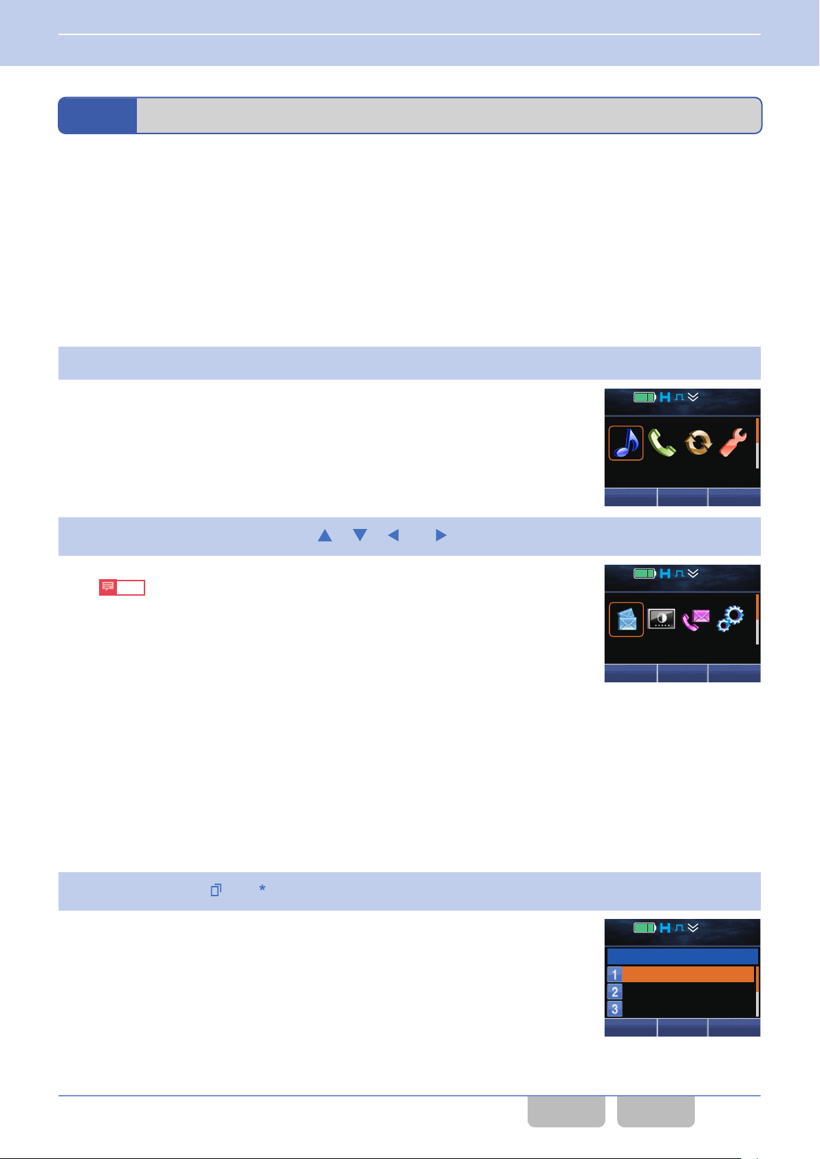
12 : 34
A
M
Audio 1
Next
12 : 34
A
M
Message 5
Next
Next
12 : 34
A
M
Individual
Group
Status
Back
Call
1
3 BASIC OPERATIONS
3.4 Using Menu Mode
3.4
Menu Mode allows a selecting a function in the menu format and activating the function.
a maximum of 64 functions can be configured for a maximum of 12 categories, many functions can be used in Menu
Since
Mode.
Using Menu Mode
Operating the transceiver
The following procedure is an example of the user operation in Menu Mode. Displays and operation methods vary depending
on the configuration in Menu Icon Size.
If “Large” is configured in Menu Icon Size
0
Press the Menu key.
1
The transceiver enters Menu Mode and then category icons appear.
Select a category by pressing the [
2
Note
0
If other function icons are in the rows below and the [F] key is pressed
while the focus is at the right end of the current row, the function icons
in the row directly below appear and the focus moves to the left end of
this row directly below. If other function icons are not in the rows below
the [F] key is pressed while the focus is at the right end of the current
and
row, a Rollover Tone (1 beep) sounds from the transceiver, and then the
focus moves to the left end of the current row.
0
If other function icons are in the rows above and the [E] key is pressed
while the focus is at the left end of the current row, the function icons in
the row directly above appear and the focus moves to the left end of this
row directly above. If other function icons are not in the rows above and
the [E] key is pressed while the focus is at the left end of the current row,
a Rollover Tone (1 beep) sounds from the transceiver, and then the focus
moves to the right end of the current row.
Press the Menu ([ ]) or [ ] key.
3
The Function List for the selected category appears.
], [ ], [ ], or [ ] key.
Common FUNC (K, F)/Ver 2.20 37
CONTENTS INDEX
Page 69
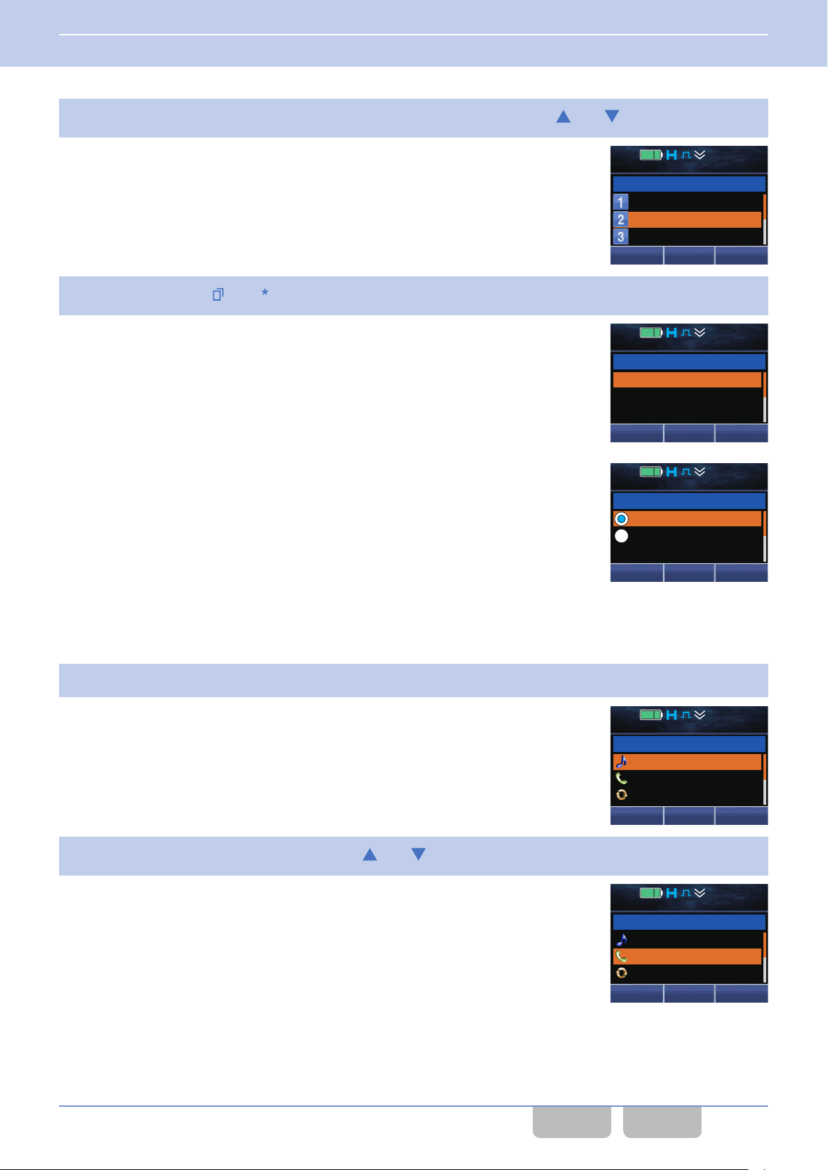
Next
12 : 34
A
M
Individual
Group
Status
Back
Call
2
12 : 34
A
M
Group 001
Group 002
Group 003
Back
Group
1
OK
12 : 34
A
M
Off
On
Low TX Power 1
Back
Next
12 : 34
A
M
Audio/Tone
Call
Scan
Menu
1
Next
12 : 34
A
M
Audio/Tone
Call
Scan
Menu 2
3 BASIC OPERATIONS
3.4 Using Menu Mode
Select the function to be started from the Function List by pressing the [ ] or [ ] key.
4
Press the Menu ([ ]) or [ ] key.
5
The selected function functions.
Options for a function, such as “ON” and “OFF”, can be selected by
pressing the [G]
Menu ([Q]) or [*] key.
If “Small” is configured in Menu Icon Size
0
Press the Menu key.
1
The transceiver enters Menu Mode and then the Category List appears.
Select the Category List by pressing the [
2
or [H] key and then can be determined by pressing the
]
or [
Example: Low Transmit Power
] key.
Common FUNC (K, F)/Ver 2.20 38
CONTENTS INDEX
Page 70
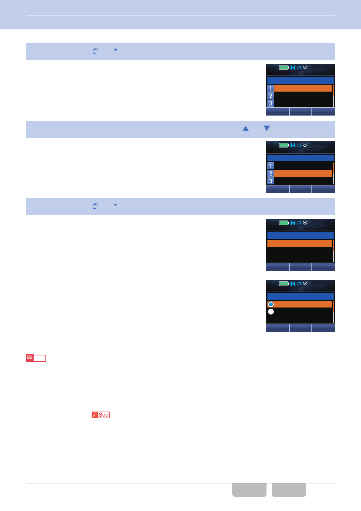
Next
12 : 34
A
M
Individual
Group
Status
Back
Call
1
Next
12 : 34
A
M
Individual
Group
Status
Back
Call
2
12 : 34
A
M
Group 001
Group 002
Group 003
Back
Group
1
OK
12 : 34
A
M
Off
On
Low TX Power 1
Back
3 BASIC OPERATIONS
3.4 Using Menu Mode
Press the Menu ([ ]) or [ ] key.
3
The Function List for the selected category appears.
Select the function to be started from the Function List by pressing the [ ] or [ ] key.
4
Press the Menu ([ ]) or [ ] key.
5
The selected function functions.
Options for a function, such as “ON” and “OFF”, can be selected by
pressing the [G]
Menu ([Q]) or [*] key.
Note
0
The category does not appear in Menu Mode when only one category is configured. When the transceiver enters Menu
Mode, the functions registered in Menu Mode appear.
0
Refer to “KEY OPERATIONS FOR EACH MODE” for the operation of each key in Menu Mode.
or [H] key and then can be determined by pressing the
Example: Low Transmit Power
Configuration using KPG-D1/ D1N
Configuring Menu Mode (
Common FUNC (K, F)/Ver 2.20 39
Transceiver Settings > Key Assignment > Menu)
CONTENTS INDEX
Page 71
3 BASIC OPERATIONS
3.5 Changing the Zone-channel
3.5
The Zone-channel can be changed using the Selector (Portable only) or PF keys.
Changing the Zone-channel
Changing the Zone
The zone can be changed by operating the Selector (Portable only) or PF keys.
Portable
Changing the zone according to the number indicated by the pointer of the Selector
0
Rotating the Selector causes
Zones that can be selected are limited to zone 1 to zone 16.
If an unprogrammed zone is selected, “**************” appears on the display.
This behavior can be realized by installing a stopper on the Selector, enabling 16 Zone/Channel Selector, and assigning
the Zone Select function to the Selector. (Refer to Available Functions for the Selector.)
Changing the zone regardless of the number indicated by the pointer of the Selector
0
Rotating the Selector clockwise increases the zone number in steps of 1. Rotating the Selector counterclockwise
decreases the zone number in steps of 1.
If an unprogrammed zone is selected, the zone will be skipped.
This behavior can be realized by disabling 16 Zone/Channel Selector and assigning the Zone Up/ Down function to the
Selector. (Refer to Available Functions for the Selector.)
the transceiver to migrate to the zone having the same number specified by the Selector.
Changing the zone by using the PF key
0
Pressing the Zone Up key increases the zone number in steps of 1. Pressing the Zone Down key decreases the zone
number in steps of 1.
If “Zone Up (Continuous)” or “Zone Down (Continuous)” is assigned to the Zone Up or Zone Down key, the zone number
is increased or decreased continuously every 200 ms by pressing and holding the Zone Up or Zone Down key.
If an unprogrammed zone is selected, the zone will be skipped.
Changing the zone by using the Lever switch
0
Positioning the Lever switch to the [A] position migrates the transceiver to the zone configured in Zone A (Lever A
Position).
Positioning the Lever switch to the [B] position migrates the transceiver to the zone configured in Zone B (Lever B
Position).
Note
The operation for changing the zone changes depending on the configuration in Rollover/
End Stop.)
End Stop. (Refer to Rollover/
Mobile
Pressing the Zone Up key increases the zone number in steps of 1. Pressing the Zone Down key decreases the zone
number in steps of 1. KCH-20R (Featured Panel) is operated by using the Selector just as Portable.
If “Zone Up (Continuous)” or “Zone Down (Continuous)” is assigned to the Zone Up or Zone Down key, the zone number
is increased or decreased continuously every 200 ms by pressing and holding the Zone Up or Zone Down key.
If an unprogrammed zone is selected, the zone will be skipped.
Note
The operation for changing the zone changes depending on the configuration in Rollover/
End Stop.)
Common FUNC (K, F)/Ver 2.20 40
CONTENTS INDEX
End Stop. (Refer to Rollover/
Page 72
3 BASIC OPERATIONS
3.5 Changing the Zone-channel
Configuration using KPG-D1/ D1N
0
Assigning functions to the PF keys on the transceiver ( Transceiver Settings > Key Assignment)
0
Configuring 16 Zone/Channel Selector to be enabled or disabled ( Transceiver Settings > Key Assignment >
Top/Side)
0
Configuring Zone A (Lever A Position) ( Transceiver Settings > Key Assignment > Zone Select)
0
Configuring Zone B (Lever B Position) ( Transceiver Settings > Key Assignment > Zone Select)
Changing the Channel
The channel can be changed using the Selector (Portable only) or PF keys.
Portable
Changing the channel according to the number indicated by the pointer of the Selector
0
Rotating the Selector
Selector. Channels that can be selected are limited to channel 1 to channel 16.
If an unprogrammed channel is selected, “**************” appears on the display.
This behavior can be realized by installing a stopper on the Selector, enabling 16 Zone/Channel Selector, and assigning
the Channel Select function to the Selector. (Refer to Available Functions for the Selector.)
causes the transceiver to migrate to the channel having the same number specified by the
Changing the channel regardless of the number indicated by the pointer of the Selector
0
Rotating the Selector clockwise increases the channel number in steps of 1. Rotating the Selector counterclockwise
decreases the channel number in steps of 1.
If an unprogrammed channel is selected, the channel will be skipped.
This behavior can be realized by disabling 16 Zone/Channel Selector and assigning the Channel Up/ Down function to
the Selector. (Refer to Available Functions for the Selector.)
Using the PF keys
0
Pressing the Channel Up key increases the channel number in steps of 1. Pressing the Channel Down key decreases
the channel number in steps of 1.
If “Channel Up (Continuous)” or “Channel Down (Continuous)” is assigned to the Channel Up or Channel Down key, the
channel number increases or decreases continuously at 200 ms intervals by pressing and holding the Channel Up or
Channel Down key.
If an unprogrammed channel is selected, the channel will be skipped.
Note
The operation for changing the channel changes depending on the configuration in Rollover/ End Stop. (Refer to
Rollover/ End Stop.)
Mobile
Pressing the Channel Up key
channel number in steps of 1. KCH-20R (Featured Panel) is operated by using the Selector just as Portable.
If “Channel Up (Continuous)” or “Channel Down (Continuous)” is assigned to the Channel Up or Channel Down key, the
channel number increases or decreases continuously at 200 ms intervals by pressing and holding the Channel Up or
Channel Down key.
If an unprogrammed channel is selected, the channel will be skipped.
increases the channel number in steps of 1. Pressing the Channel Down key decreases the
Note
The operation for changing the channel changes depending on the configuration in Rollover/ End Stop. (Refer to
Rollover/ End Stop.)
Common FUNC (K, F)/Ver 2.20 41
CONTENTS INDEX
Page 73
3 BASIC OPERATIONS
3.5 Changing the Zone-channel
Configuration using KPG-D1/ D1N
0
Assigning functions to the PF keys on the transceiver ( Transceiver Settings > Key Assignment)
0
Configuring 16 Zone/Channel Selector to be enabled or disabled ( Transceiver Settings > Key Assignment >
Top/Side)
Rollover/ End Stop
Rollover/ End Stop is
the PF keys or Selector on the transceiver.
The zone or channel migrates as below depending on the configuration using KPG-D1/ D1N when changing the zone or
channel using the PF keys or Selector on the transceiver.
Configuration Description
Rollover
End Stop
the method to configure how a zone or channel migrates when changing the zone or channel using
Table 3-5 Rollover/ End Stop
A Rollover Tone (1 beep) sounds from the transceiver and the transceiver migrates to the zone or
channel having the lowest number when attempting to increase the zone or channel number while the
zone or channel having the largest number is selected.
The
transceiver migrates to the zone or channel having the largest number when attempting to decrease
the zone or channel number while the zone or channel having the lowest number is selected.
The zone or channel in the range between the highest and lowest numbers can be selected. The zone
channel number is not looped. A Stop Tone (1 beep) sounds from the transceiver and the transceiver
or
does not migrate to a different zone or channel when attempting to increase the zone or channel number
while the zone or channel having the largest number is selected. Also, a Stop Tone (1 beep) sounds
from the transceiver and the transceiver does not migrate to a different zone or channel when attempting
to decrease the zone or channel number while the zone or channel having the lowest number is selected.
Configuration using KPG-D1/ D1N
Configuring Rollover/ End Stop (
Transceiver Settings > Optional Features > Optional Features 1 > Others)
Changing the Channel by Specifying the Number (Channel Entry)
Channel Entry can be used to directly migrate to the channel to be used.
For use of this function, pressing the Channel Entry or Group ID/Channel Entry keys causes the transceiver to enter
Channel Entry Mode.
Using the Channel Entry key
0
The channel number in the current zone can be specified by directly entering numbers after pressing the Channel
Entry key.
Also, if “Channel Entry” is configured in Keypad Operation, the channel number can be specified by pressing the [0]
[9] keys on the keypad even if the Channel Entry key is not pressed.
Using the Group ID/Channel Entry key
0
While a zone other than an NXDN Trunking system zone is selected, the channel in the current zone can be specified by
directly entering numbers after pressing the Group ID/Channel Entry key.
Also, if “Group ID/Channel Entry” is configured in Keypad Operation, the channel can be specified by pressing the [0]
to [9] keys on the keypad while a zone other than an NXDN Trunking system zone is selected.
The transceiver automatically recognizes the digits of the highest channel number configured for the transceiver. The
channel number can be entered within this range of digits.
to
Common FUNC (K, F)/Ver 2.20 42
CONTENTS INDEX
Page 74
OK
12 : 34
A
M
[ 001]
Channel No. ___
Low TX Power 1Channel Entry
3 BASIC OPERATIONS
3.5 Changing the Zone-channel
Operating the transceiver
Press the Channel Entry key,
1
NXDN Trunking system zone.
The transceiver enters Channel Entry Mode.
The following operations are identical even if the transceiver enters
Channel Entry Mode by using the keypad.
Enter the channel number.
2
The following are examples for entering a channel number by using the keypad.
If the maximum channel number has 3 digits:
0
To make a call on channel 250, press the [2], [5] and [0] keys in this order.
To make a call on channel 90, press the [0], [9] and [0] keys in this order.
To make a call on channel 7, press the [0], [0] and [7] keys in this order.
If the maximum channel number has 2 digits:
0
To make a call on channel 90, press the [9] and [0]
To make a call on channel 7, press the [0] and [7] keys in this order.
If the maximum channel number has 1 digit:
0
To make a call on channel 7, press the [7] key.
If the maximum number of digits is entered, the transceiver exits Channel Entry Mode and then migrates to the
channel of the entered channel number.
or press the Group ID/Channel Entry key after selecting a zone other than an
keys in this order.
Press the Menu ([ ]) key.
3
The transceiver exits Channel Entry Mode and then migrates to the channel of the entered number.
there is no channel of the entered channel number, a Key-entry Error Tone (1 beep) sounds from the transceiver,
If
and then the transceiver exits Channel Entry Mode.
Note
0
Refer to “KEY OPERATIONS FOR EACH MODE” for key operations for entering the channel number in Channel Entry
Mode.
0
channel number selected before the transceiver enters Channel Entry Mode appears on the display, such as “[001]”.
The
Pressing the Menu ([Q]) or [*] key while no channel number is entered causes the transceiver to exit Channel Entry Mode
and then to return to this channel number.
0
If the transceiver exits Channel Entry Mode by pressing the Home ([T]) key, the transceiver returns to the channel
selected before the transceiver entered Channel Entry Mode.
0
Pressing the PTT switch while in Channel Entry Mode causes the transceiver to transmit on the channel selected before
the transceiver entered Channel Entry Mode.
0
If the channel is changed while in Channel Entry Mode, pressing the PTT switch initiates transmission on the channel to
which the transceiver has changed.
0
If no key is pressed before the amount of time configured in Mode Reset Timer elapses, the transceiver exits Channel
Entry Mode and then returns to the channel selected before the transceiver entered Channel Entry Mode.
Configuration using KPG-D1/ D1N
Assigning functions to the PF
Common FUNC (K, F)/Ver 2.20 43
keys on the transceiver (
Transceiver Settings > Key Assignment)
CONTENTS INDEX
Page 75
OK
12 : 34
A
M
[00001]
Group
ID ___
Group Entry
3 BASIC OPERATIONS
3.5 Changing the Zone-channel
Changing the Group ID by Specifying the ID (Group ID Entry) (NXDN Trunking
System Only)
Group ID Entry is
be used in an NXDN Trunking system.
The Group ID to be used can be specified by directly entering a Group ID after pressing the Group ID/Channel Entry key
when a zone in an NXDN Trunking system is selected.
Also, if “Group ID/Channel Entry” is configured in Keypad Operation, the Group ID can be specified by pressing the [0] to
[9] keys on the keypad while a zone in an NXDN Trunking system is selected.
By specifying a Group ID configured for a zone in an NXDN Trunking system, the transceiver can migrate to a channel with
the Group ID.
The transceiver automatically recognizes the digits of the highest Group ID in all the zones in an NXDN Trunking system
configured for the transceiver.
the function to migrate the transceiver to the channel with the Group ID which is directly selected and to
Operating the transceiver
Press the Group ID/Channel Entry key after an NXDN Trunking system zone is selected.
1
The transceiver enters Group ID Entry Mode.
following operations are identical even if the transceiver enters Group
The
ID Mode by using the keypad.
Enter a Group ID.
2
The following are examples for entering a Group ID by using the keypad.
If the maximum Group ID has 5 digits:
0
To enter Group ID 21250, press the [2], [1], [2], [5] and [0]
To enter Group ID 1250, press the [0], [1], [2], [5] and [0] keys in this order.
To enter Group ID 250, press the [0], [0], [2], [5] and [0] keys in this order.
To enter Group ID 90, press the [0], [0], [0], [9] and [0] keys in this order.
To enter Group ID 7, press the [0], [0], [0], [0] and [7] keys in this order.
If the maximum Group ID has 4 digits:
0
To enter Group ID 1250, press the [1], [2], [5] and [0] keys in this order.
To enter Group ID 250, press the [0], [2], [5] and [0] keys in this order.
To enter Group ID 90, press the [0], [0], [9] and [0] keys in this order.
To enter Group ID 7, press the [0], [0], [0] and [7] keys in this order.
If the maximum Group ID has 3 digits:
0
To enter Group ID 250, press the [2], [5] and [0] keys in this order.
To enter Group ID 90, press the [0], [9] and [0] keys in this order.
To enter Group ID 7, press the [0], [0] and [7] keys in this order.
If the maximum Group ID has 2 digits:
0
To enter Group ID 90, press the [9] and [0] keys in this order.
To enter Group ID 7, press the [0] and [7] keys in this order.
If the maximum Group ID has 1 digit:
0
To enter Group ID 7, press the [7] key.
If the maximum number of digits is entered, the transceiver exits Group ID Entry Mode and then migrates to the
channel of the entered Group ID.
keys in this order.
Common FUNC (K, F)/Ver 2.20 44
CONTENTS INDEX
Page 76
Menu Zone
+
Home
Zone 1
Channel 1
12 : 34
A
M
3 BASIC OPERATIONS
3.5 Changing the Zone-channel
Press the Menu ([
3
The transceiver exits Group ID Entry Mode and then migrates to the channel of the entered Group ID.
there is no channel with the entered Group ID, a Key-entry Error Tone (1 beep) sounds from the transceiver, and
If
then the transceiver exits Group ID Entry Mode.
Note
0
Refer to “KEY OPERATIONS FOR EACH MODE”
0
Pressing the PTT switch while in Group ID Entry Mode causes the transceiver to transmit on the channel selected before
the transceiver entered Group ID Entry Mode. If the channel is changed while in Group ID Entry Mode, pressing the PTT
switch initiates transmission on the channel to which the transceiver has changed.
]) key.
for key operations for entering the Group ID in Group ID Entry Mode.
Configuration using KPG-D1/ D1N
Assigning functions to the PF keys on the transceiver (
Transceiver Settings > Key Assignment)
Changing the Channel with a Single Touch
The channel can be changed with a single touch by using the Home Channel or Direct Channel function.
Home Channel
Home Channel is the function to migrate the transceiver to a preconfigured channel by pressing the Home Channel key.
The transceiver can move to and from channels in the same zone.
Also, pressing the Home Channel Select key can change the Home Channel.
Or, pressing the Menu key causes the transceiver to enter Menu Mode, and then the Home Channel can be changed by
selecting “Home Channel Select”. (Refer to Using Menu Mode.)
Note
If the Home Channel key
to the Home Channel, and then a Scan Stop Tone (2 beeps) continuously sounds from the transceiver at 30-sec intervals.
is pressed during the scan, the transceiver pauses scanning while the transceiver is migrating
Operating the transceiver
Migrating to the Home Channel
0
Press the Home Channel key.
1
A Key Beep A (1 beep) sounds from the transceiver, and then the
transceiver migrates to the Home Channel configured for the selected
zone. “Home” appears on the display.
Common FUNC (K, F)/Ver 2.20 45
CONTENTS INDEX
Page 77
Menu Zone
+
Zone 1
Channel 15
12 : 34
A
M
Menu Zone
+
Zone 1
Channel 15
12 : 34
A
M
Menu Zone
+
Home
Zone 1
Channel 15
12 : 34
A
M
3 BASIC OPERATIONS
3.5 Changing the Zone-channel
Press the Home Channel key again.
2
A Key Beep B (2 beeps) sounds from the transceiver, and then the
transceiver returns to the previous channel.
Changing the Home Channel
0
Select the channel to be configured as the Home Channel.
1
Press the Home Channel Select key.
2
A Key Beep C (3 beeps) sounds from the transceiver, and then the Home
Channel is changed. “Home” appears on the display at the same time.
Configuration using KPG-D1/ D1N
0
Configuring Home Channel ( Transceiver Settings > Zone/Channel > Zone Edit > General)
0
Assigning functions to the PF keys on the transceiver ( Transceiver Settings > Key Assignment)
Direct Channel
Direct Channel is the function to migrate the transceiver to a preconfigured channel by pressing one of the Direct Channel
1
to Direct Channel 5 keys. The transceiver can move to and from channels in each zone.
Also, pressing one of the Direct Channel 1 Select to Direct Channel 5 Select keys can change the Direct Channel.
Or, pressing the Menu key causes the transceiver to enter Menu Mode, and then the Direct Channel can be changed by
selecting one of “Direct Channel 1 Select” to “Direct Channel 5 Select”. (Refer to Using Menu Mode.)
Common FUNC (K, F)/Ver 2.20 46
Note
If the Return function is enabled, pressing one of the Direct
scanning while the transceiver is migrating to the Direct Channel, and then a Scan Stop Tone (2 beeps) continuously
sounds from the transceiver at 30-sec intervals.
Channel 1 to Direct Channel 5 keys during the scan pauses
CONTENTS INDEX
Page 78
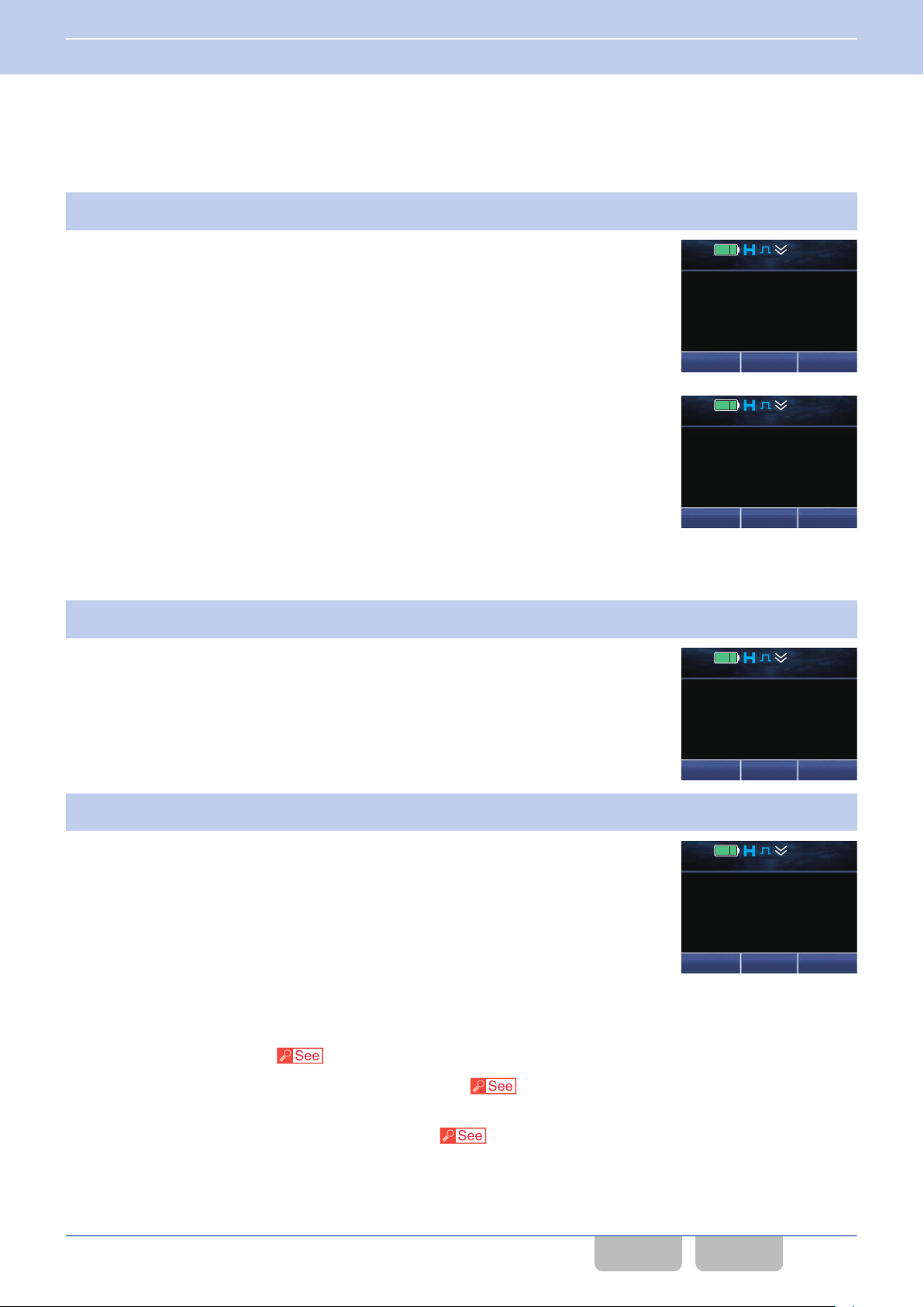
Menu Zone
+
DR1
Zone 1
Channel 1
12 : 34
A
M
Menu Zone
+
Zone 1
Channel 15
12 : 34
A
M
Menu Zone
+
Zone 1
Channel 15
12 : 34
A
M
Menu Zone
+
DR1
Zone 1
Channel 15
12 : 34
A
M
3 BASIC OPERATIONS
3.5 Changing the Zone-channel
Operating the transceiver
Migrating to the Direct Channel
0
Press one of the Direct Channel 1 to Direct Channel 5 keys.
1
A Key Beep A (1 beep) sounds from the transceiver, and then the
transceiver
“DRn” appears on the display. The selected Direct Channel number is
entered in “n”.
If the same Direct Channel key is pressed again while the Return function
is enabled, a Key Beep B (2 beeps) sounds from the transceiver, and then
the transceiver returns to the previous channel.
migrates to the Direct Channel regardless of the selected zone.
Changing the Direct Channel
0
Select the channel to be configured as the Direct Channel.
1
Press one of the Direct Channel 1 Select to Direct Channel 5 Select
2
A Key Beep C (3 beeps) sounds from the transceiver, and then the Direct
Channel is changed. “DRn” appears on the display at the same time.
keys.
Configuration using KPG-D1/ D1N
0
0
0
Common FUNC (K, F)/Ver 2.20 47
Configuring Direct Channel ( Transceiver Settings > Key Assignment > Direct Channel)
Configuring the Return function to be enabled or disabled ( Transceiver Settings > Key Assignment > Direct
Channel)
Assigning functions to the PF keys on the transceiver ( Transceiver Settings > Key Assignment)
CONTENTS INDEX
Page 79

3 BASIC OPERATIONS
3.6 Transmitting/ Receiving
3.6
The PTT
Transmitting/ Receiving
switch can be used to transmit and receive.
Receiving
Received audio sounds from the speaker when the transceiver receives a signal and conditions to unmute the speaker are
satisfied. To respond, speak into the microphone while pressing the PTT switch.
Transmitting
Transmitting can be initiated by selecting the desired Zone-channel and then pressing the PTT switch.
by speaking into the microphone while pressing the PTT switch. Releasing the PTT switch terminates transmitting.
Conditions to unmute the speaker while receiving, the transceiver behavior while transmitting, or communication methods,
such as an individual call or group call, vary according to the system in use. Refer to each Function Reference for
communication methods in each system.
In addition, for Mobile, various communications can be done using the external ports of the transceiver. Refer to “D-sub 25-
pin Connector” for the function of the external ports of Mobile.
Note
Audio characteristics of the microphone and speaker for transmitting and receiving can be configured in Audio Profile.
(Refer to Configuring Audio Profile (Audio Profile).)
Audio is transmitted
Common FUNC (K, F)/Ver 2.20 48
CONTENTS INDEX
Page 80
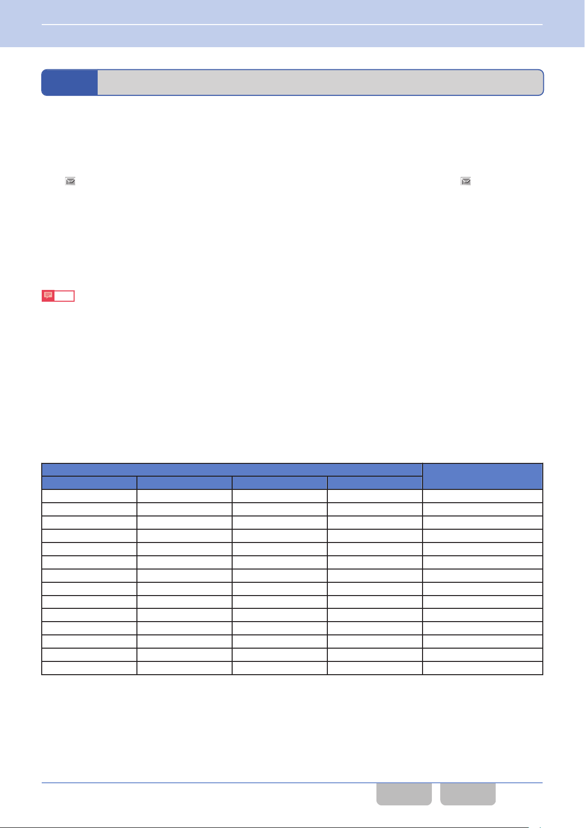
3 BASIC OPERATIONS
3.7 Viewing the Receive History (Stack)
3.7
In Stack Mode, the incoming call history (Caller ID) can be viewed. In an analog system (FleetSync/ MDC-1200/ 5-tone),
an NXDN system, or a DMR Conventional system, in addition to the incoming call history, received Status Messages and
Short Messages can be viewed in Stack Mode. Received IDs and messages are stored in the stack memory of the
transceiver.
In order to store the received IDs and various messages in the stack memory of the transceiver, Caller ID Stack, Status
Message Stack, or Short Message Stack needs to be individually enabled by using KPG-D1/ D1N.
The “
Pressing the Stack key causes the transceiver to enter Stack Mode. Or, pressing the Menu key causes the transceiver to
enter
Menu Mode, and then selecting “Stack” will cause the transceiver to enter Stack Mode. (Refer to Using Menu Mode.)
Viewing the Receive History (Stack)
” icon appears if messages are stored in the transceiver. If there is an unread message, the “ ” icon blinks.
The maximum number of stack data that can be stored
Caller ID/ Status Message
0
A maximum of 250 Caller IDs and Status Messages in total can be stored in the stack memory.
Note
Depending on the configuration of Old
(Refer to Stack Procedure of the Receive History (Old Message Overwrite).)
If the configuration is to automatically delete the old data:
Assume that one voice call and 249 Status Messages are stored, and that the voice call is the oldest data. In this case,
if a newly received Status Message is stored, the data of the voice call is deleted and 250 Status Messages are stored.
If the configuration is not to automatically delete the old data:
Assume that 250 Status Messages are stored. In this case, even if a new voice call is received, the voice call is not stored
because 250 Status Messages are stored.
Message Overwrite, the stack data is deleted or stored like the following examples:
Short Message
0
The maximum number of Short Message data that can be stored in the transceiver stack memory varies as follows
depending on the configuration of Short Message Stack in each communication protocol.
Table 3-6 No. of Short Message Data That can be Stored
Short Message Stack Configuration
FleetSync NXDN P25 DMR
Disabled Disabled Disabled Disabled 0
Enabled Disabled Disabled Disabled 128
Disabled Enabled Disabled Disabled 128
Enabled Enabled Disabled Disabled 128
Disabled Disabled Enabled Disabled 64
Enabled Disabled Enabled Disabled 64
Disabled Enabled Enabled Disabled 64
Enabled Enabled Enabled Disabled 64
Disabled Disabled Disabled Enabled 32
Enabled Disabled Disabled Enabled 32
Disabled Enabled Disabled Enabled 32
Enabled Enabled Disabled Enabled 32
Disabled Disabled Enabled Enabled 32
Enabled Disabled Enabled Enabled 32
No. of Data that Can be
Saved
Common FUNC (K, F)/Ver 2.20 49
CONTENTS INDEX
Page 81
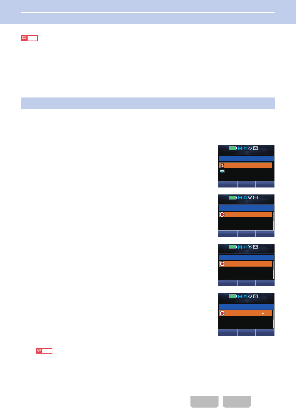
Next
Stack 1
12 : 34
A
M
Caller ID
Status Message
Back
Call
Caller ID 001
12 : 34
A
M
TRUCK 824
TRUCK 824
TRUCK 825
Delete
Status Message 001
12 : 34
A
M
In Service
Call Office
Call Home
Delete
Status Message 001
12 : 34
A
M
Please pick up
Good morning
Good night
View Delete
3 BASIC OPERATIONS
3.7 Viewing the Receive History (Stack)
Note
The following are the notes only for an NXDN Conventional system and NXDN Trunking system:
0
If the transceiver receives a Group Call from a telephone, the Caller ID is replaced with “Phone Call” and stored in the
stack memory of the transceiver.
0
The Caller ID stored by the transceiver receiving a Group Call from a telephone cannot be called.
Operating the transceiver
Confirming the message
0
Press the Stack key.
1
A Key Beep A (1 beep) sounds from the transceiver and the transceiver enters Stack Mode. The subsequent
operations are identical even if the transceiver enters Stack Mode by pressing the Menu key.
The display when the transceiver enters Stack Mode varies depending on the configurations of Caller ID Stack,
Status Message Stack, and Short Message Stack in each communication protocol, and depending on the
presence of stored data.
data is stored with 2 items or more among Caller ID Stack, Status
If
0
Message Stack, and Short Message Stack enabled
The category display appears. Proceed to step 2.
If data is stored with only Caller ID Stack enabled
0
The list of stored Caller IDs appears. Proceed to step 3.
If data is stored with only Status Message Stack enabled
0
The list of stored Status Messages appears. Proceed to step 3.
If data is stored with only Short Message Stack enabled
0
The list of stored Short Messages appears. Proceed to step 3.
0
If no data is stored, “Empty” appears on the display for 1 sec and the transceiver cannot enter Stack Mode.
0
If at least one system whose Signaling Type is 5-tone is configured, the transceiver determines that Caller ID
Stack, Status Message Stack, and Short Message Stack are all enabled, and the transceiver migrates to the
category display.
Common FUNC (K, F)/Ver 2.20 50
Note
CONTENTS INDEX
Page 82
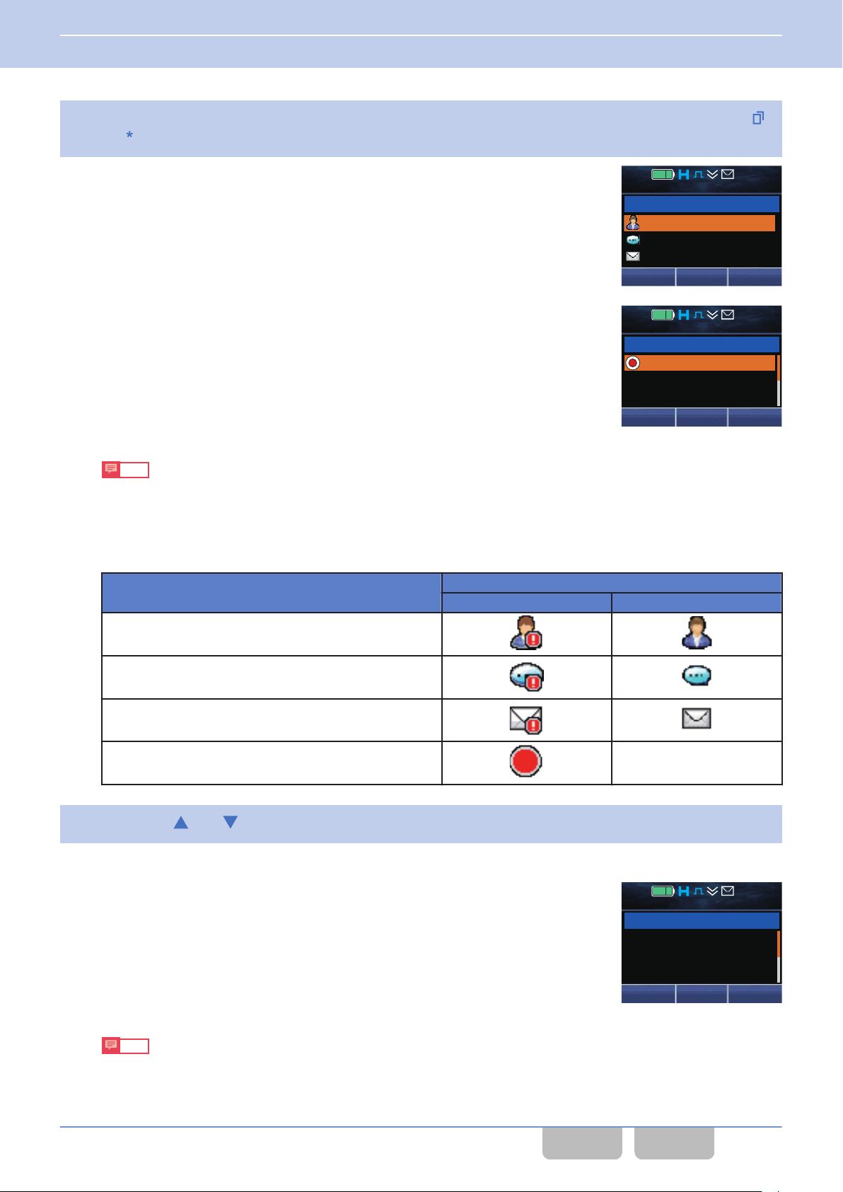
Next
Short Message
Stack 1
12 : 34
A
M
Caller ID
Status Message
Back
Call
Caller ID 001
12 : 34
A
M
TRUCK 824
TRUCK 824
TRUCK 825
Delete
TRUCK 824
001
12 : 34
A
M
Please pick up
customers at
airport terminal
Back
3 BASIC OPERATIONS
3.7 Viewing the Receive History (Stack)
Select any of the “Caller ID”, “Status Message”, or “Short Message” categories and press the Menu ([ ])
2
or [ ] key.
The list for the selected category appears.
Note
If no data is stored, a Key Beep A (1 beep) sounds from the transceiver and “Empty” appears on the display.
The number of the stored stack data appears at the upper right of the display. Depending on the type of stack
data, the following icons appear at the left end of each stack data:
Table 3-7 Stack Mode
Message Type
Caller ID
Status Message
Short Message
Unread Stack -
Press the [ ] or [ ] key to select the data and confirm.
3
Refer to “Selecting or Clearing Data from a List” for selection methods.
Unread Read
Display
Common FUNC (K, F)/Ver 2.20 51
For Short Message, if the Menu
(1 beep) sounds from the transceiver and the selected Short Message
appears.
Note
If the Short Message does not fit on one screen, press the [G]
the entire message.
([Q]) or [*] key is pressed, a Key Beep A
or [H] key to scroll lines up and down, and confirm
CONTENTS INDEX
Page 83
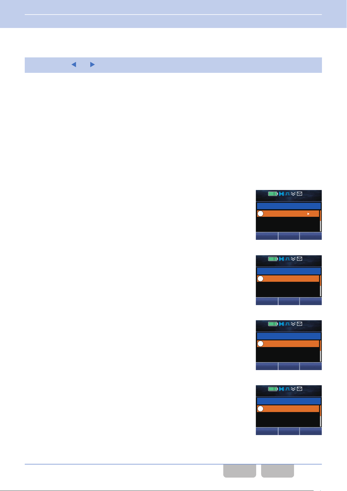
Short Message 001
12 : 34
A
M
Delete
Please pick up
Good morning
Good night
View
Short Message 001
12 : 34
A
M
Delete
TRUCK 824
TRUCK 824
TRUCK 825
View
Short Message 001
12 : 34
A
M
Delete
Channel 1
Channel 1
Channel 2
View
Short Message 001
12 : 34
A
M
Delete
04/21/’ 14 10:23A
04/20/’ 14 10:09P
04/20/’ 14
8:05A
View
3 BASIC OPERATIONS
3.7 Viewing the Receive History (Stack)
Switching the message display
0
Press the [ ] or [ ] key.
1
The display switches as follows:
[E] key:
0
Caller ID
Caller ID List N Receive Channel List N Receive Date and Time List N
0
Status/ Short Message
Status/ Short Message List N Caller ID List N Receive Channel List N Receive Date and Time List N Status/
Short Message List N ...
[F] key:
0
Caller ID
Caller ID List N Receive Date and Time List N Receive Channel List N Caller ID List N ...
0
Status/ Short Message
Status/ Short Message List N Receive Date and Time List N Receive Channel List N Caller ID List N Status/
Short Message List N ...
Caller ID List N ...
Status/ Short Message list
0
The received Status Messages and Short Messages are displayed.
Caller ID Name list
0
The ID Names of the transceivers which sent messages are displayed.
If a Caller ID is displayed, press the PTT switch to respond. (Only if the
type of the stored message is Caller ID.)
Receive channel list
0
The channel names of the transceivers which received messages are
displayed.
Common FUNC (K, F)/Ver 2.20 52
Receive date and time list
0
The dates and times of received messages are displayed.
CONTENTS INDEX
Page 84
3 BASIC OPERATIONS
3.7 Viewing the Receive History (Stack)
Note
0
The receive date and time list is displayed only if Time Stamp is enabled. (Refer to Time Stamp.)
0
Refer to Selecting or Clearing Data from a List for instructions on how to clear a message.
0
For Caller ID Stack, if System Type of the selected channel when the transceiver enters Stack Mode does not match
System Type of the stack data, a Warning Tone A (continuous beep) sounds from the transceiver and transmission is
unavailable
Tone (1 beep) sounds from the transceiver and transmission is unavailable.
even if the PTT switch is pressed. Also in this case, even if the Menu ([Q]) key is pressed, a Key-entry Error
Configuration using KPG-D1/ D1N
0
Assigning functions to the PF
0
Configuring Caller ID Stack (P25) ( Transceiver Settings > P25 > P25 Information > General > Stack)
0
Configuring Caller ID Stack (NXDN) ( Transceiver Settings > NXDN > NXDN Information > General > Stack)
0
Configuring Caller ID Stack
> Stack)
0
Configuring Caller
> Stack)
0
Configuring Status Message Stack (NXDN) (
Stack)
0
Configuring Status Message Stack (NXDN) ( Transceiver Settings > NXDN > NXDN Information > General >
Stack)
0
Configuring Caller ID Stack (DMR) ( Transceiver Settings > DMR > DMR Information > General > Stack)
0
Configuring Status
0
Configuring Short Message Stack (DMR) ( Transceiver
0
Configuring Short Message Stack (FleetSync) (
General > Stack)
0
Configuring Short Message Stack
General > Stack)
ID Stack (MDC-1200) (
Message Stack (DMR) (
keys on the transceiver ( Transceiver Settings > Key Assignment)
(FleetSync) (
(FleetSync) (
Transceiver Settings > FleetSync > FleetSync Information > General
Transceiver Settings > MDC-1200 > MDC-1200 Information > General
Transceiver Settings > NXDN > NXDN Information > General >
Transceiver Settings > DMR > DMR Information > General > Stack)
Settings > DMR > DMR Information > General > Stack)
Transceiver Settings > FleetSync > FleetSync Information >
Transceiver Settings > FleetSync > FleetSync Information >
Common FUNC (K, F)/Ver 2.20 53
CONTENTS INDEX
Page 85
3 BASIC OPERATIONS
3.7 Viewing the Receive History (Stack)
Configuring the Display Order of Data in Stack Mode (Stack Order)
Stack Order is the display order of data in Stack Mode.
Depending on the configuration of Stack Order, the data is displayed in Stack Mode as follows:
Table 3-8 Stack Order
Configuration Description
Descending The newest data appears on the first line of the list.
Ascending The oldest data appears on the first line of the list.
Configuration using KPG-D1/ D1N
Configuring Stack Order
(
Transceiver Settings > Optional Features > Optional Features 1 > Stack)
Enabling the Storage of Redundant Data (Repeated Calls Stack)
Repeated Calls Stack is the function to enable the storage of redundant data.
If Repeated Calls Stack is enabled, a Caller ID or message is stored as new data in the stack memory of the transceiver
even if the same Caller ID or message has been previously received.
Configuration using KPG-D1/ D1N
Configuring Repeated
Features 1 > Stack)
Calls Stack to be enabled or disabled (
Transceiver
Settings > Optional Features > Optional
Displaying the Caller ID when Displaying a Message (Caller ID for Message)
Caller ID for Message
is displayed in Stack Mode.
is the function to display the Caller ID of the stored data when the Status Message or Short Message
Configuration using KPG-D1/ D1N
Configuring Caller
Features 1 > Stack > Message Display)
ID for Message to be enabled or disabled (
Common FUNC (K, F)/Ver 2.20 54
Transceiver
Settings > Optional Features > Optional
CONTENTS INDEX
Page 86
3 BASIC OPERATIONS
3.7 Viewing the Receive History (Stack)
Displaying the Receive Channel (Channel Name (Message Display))
Channel Name (Message Display) is the function to display the receive channel of the stored data in Stack Mode.
Configuration using KPG-D1/ D1N
Configuring Channel Name (Message Display) to be enabled or disabled ( Transceiver Settings > Optional
Features > Optional Features 1 > Stack > Message Display)
Stack Procedure of the Receive History (Old Message Overwrite)
Old Message Overwrite
memory of the transceiver.
Configuration Description
Enabled
Disabled
is the method to store the received Caller IDs, Status Messages, and Short Messages in the stack
Table 3-9 Old Message Overwrite
The transceiver stores a received ID or message in the stack memory in the order of receipt to the maximum number of
received IDs and messages. If IDs or messages are received in excess of the maximum number of received IDs and
messages, the oldest stored ID or message is deleted and the new ID or message is stored in the stack memory. In Stack
Mode, the newest stack data is displayed as list number 1.
The transceiver stores a received ID or message in the stack memory in the order of receipt to the maximum number of
received IDs and messages. If IDs or messages are received in excess of the maximum number of received IDs and
messages, the ID or message is not stored in the stack memory. In Stack Mode, the oldest stack data is displayed as list
number 1.
Configuration using KPG-D1/ D1N
Configuring Old Message Overwrite to be enabled or disabled ( Transceiver Settings > Optional Features >
Optional Features 1 > Stack)
Common FUNC (K, F)/Ver 2.20 55
CONTENTS INDEX
Page 87
3 BASIC OPERATIONS
3.7 Viewing the Receive History (Stack)
Caller ID Stack
Caller ID Stack is the function to store IDs of callers in the stack memory.
The transceiver can store a maximum of 250 Caller IDs.
By selecting a Caller ID and pressing the PTT switch while in Stack Mode, the transceiver can respond to the Caller ID.
the transceiver receives a call, the “
When
Mode, a user can check the stored IDs.
” icon blinks to notify that the ID is being saved. If the transceiver enters Stack
About the Caller ID Stack configuration
The transceiver behaves as follows according to the configuration in Caller ID Stack:
Table 3-10 Caller ID Stack
Configuration Description
None The Caller ID is not stored even if a call is received.
Individual Call Only the Caller ID of an Individual Call or Paging Call is stored.
Any Call
The Caller IDs of all calls are stored. However, the Caller IDs of Unaddressed Calls and Broadcast Group
Calls are not stored in a DMR Conventional system.
Note
0
The transceiver stores in combination a maximum of 250 Caller IDs and Status Messages in the stack memory. If no
Status Message is stored, the transceiver stores up to 250 Caller IDs.
0
The storage method varies depending on the configuration in Old Message Overwrite.
Configuration using KPG-D1/ D1N
0
Configuring Caller ID Stack (P25) to be enabled of disabled ( Transceiver Settings > P25 > P25 Information >
General > Stack)
0
Configuring Caller ID Stack
0
Configuring Caller ID Stack
> Stack)
0
Configuring Caller
> Stack)
0
Configuring Caller ID Stack (DMR) ( Transceiver Settings > DMR > DMR Information > General > Stack)
ID Stack (MDC-1200) (
(NXDN) (
(FleetSync) (
Transceiver Settings > NXDN > NXDN Information > General > Stack)
Transceiver Settings > FleetSync > FleetSync Information > General
Transceiver Settings > MDC-1200 > MDC-1200 Information > General
Common FUNC (K, F)/Ver 2.20 56
CONTENTS INDEX
Page 88
3 BASIC OPERATIONS
3.7 Viewing the Receive History (Stack)
Time Stamp
Time Stamp is the function to store a Caller ID, Status Message or Short Message with the stamp of the received time in
the stack memory.
Configuration using KPG-D1/ D1N
Configuring Time Stamp ( Transceiver Settings > Optional Features > Optional Features 1 > Stack > Message
Display)
Message Memory
Message Memory
of the transceiver even after the transceiver is turned OFF.
is the function to retain the stored Caller IDs, Status Messages, or Short Messages in the stack memory
Configuration using KPG-D1/ D1N
Configuring Message Memory (
Transceiver Settings > Optional Features > Optional Features 1 > Stack)
Clear Caller ID Stack on Reply
Clear Caller ID Stack on Reply is
stored in the stack memory is selected and called.
This function is used if not storing used Caller IDs in the stack memory of the transceiver.
If this function is enabled, a Caller ID is cleared from the stack memory of the transceiver if the Caller ID stored in the stack
memory is selected and called. The Caller ID is cleared from the stack memory even if a call cannot be initiated since the
channel is busy. If the transceiver receives a response from the target party, the Caller ID is not stored in the stack memory
while the Auto Reset Timer is counting down.
Also, the Caller ID of the calling party is store in the stock memory when the transceiver receives a call, but the Caller ID is
cleared from the stack memory if a response is initiated while the Auto Reset Timer is counting down. Subsequently, the
Caller ID is not stored in the stack memory even if a call from the same party is received while the Auto Reset Timer is
counting down.
the function to clear a Caller ID from the stack memory of the transceiver if the Caller ID
Configuration using KPG-D1/ D1N
0
Configuring Clear Caller ID Stack on Reply (NXDN) to be enabled or disabled (
> NXDN Information > General)
0
Configuring Clear Caller ID Stack on Reply (DMR) to be enabled or disabled ( Transceiver Settings > DMR >
DMR Information > General)
Common FUNC (K, F)/Ver 2.20 57
CONTENTS INDEX
Transceiver Settings > NXDN
Page 89
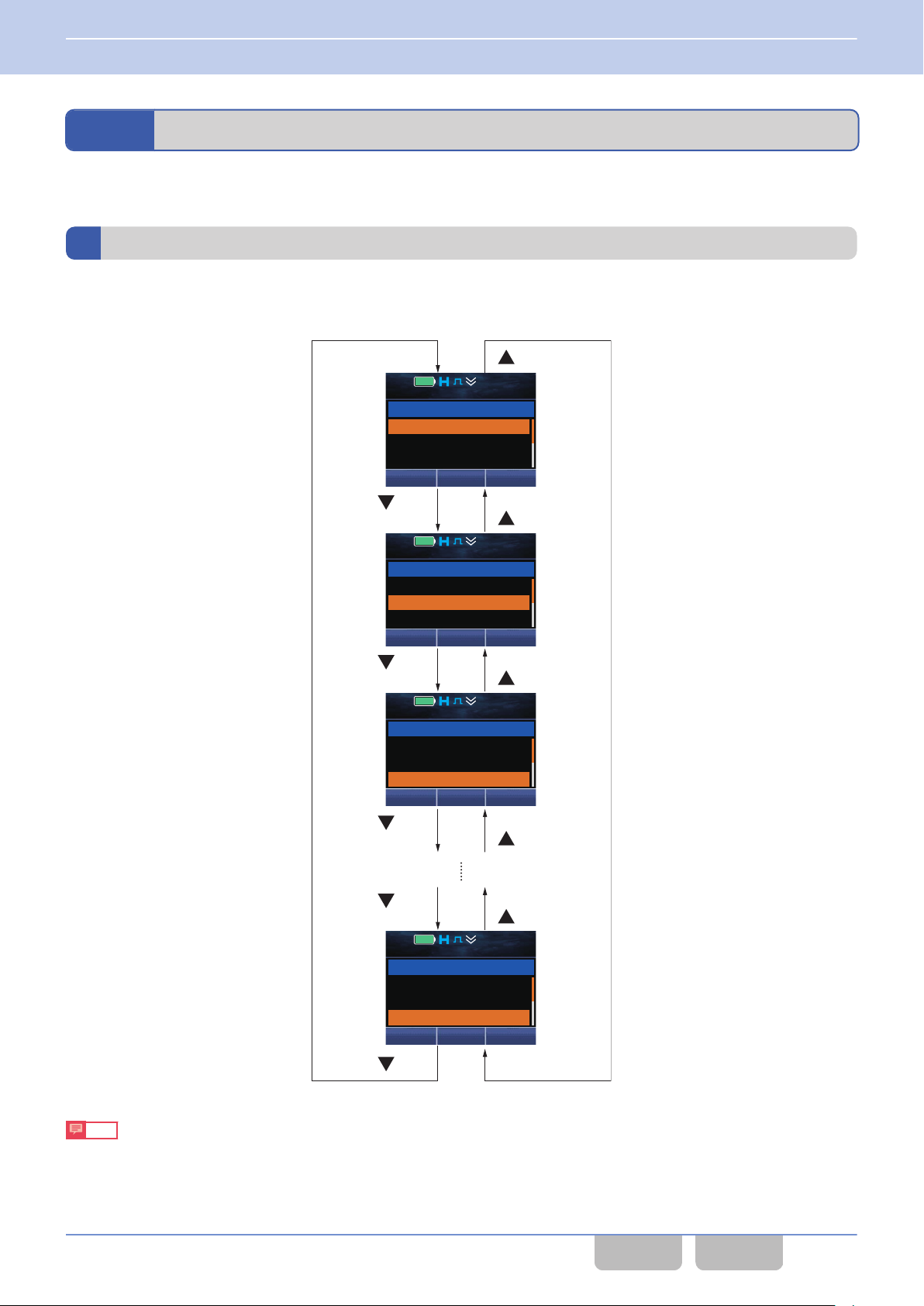
[ ] key
[ ] key
[ ] key
[ ] key
[ ] key
[ ] key
[ ] key
[ ] key
[ ] key
[ ] key
Call
12 : 34
A
M
ID 0001
ID 0002
ID 0003
Individual
0001
Back
Call
12 : 34
A
M
ID 0001
ID 0002
ID 0003
Back
Individual
0002
Call
12 : 34
A
M
ID 0001
ID 0002
ID 0003
Back
Individual
0003
Call
12 : 34
A
M
ID 0998
ID 0999
ID 1000
Back
Individual
1000
3 BASIC OPERATIONS
3.8 Operating the Transceiver in Each Mode (Common Operation)
3.8
Operating the Transceiver in Each Mode (Common Operation)
This section describes operations common to transceivers, such as list selection, character entry, etc.
Selecting or Clearing Data from a List
This section explains operations using operating examples for Individual Call Mode and Playback Mode.
0
Selecting data from a list by using the [G] or [H] key
Note
0
The list number automatically scrolls up or down continuously while the [G] or [H] key is pressed and held.
0
displays above are the displays when Individual Call Acknowledge Request in an NXDN Conventional system is
The
enabled.
Common FUNC (K, F)/Ver 2.20 58
CONTENTS INDEX
Page 90

[0] key
[2] key
[4] key
[5] key
Menu ([ ]) or
[*] key (OK)
Menu ([ ]) or
[*] key (OK)
Menu ([ ]) or
[*] key (OK)
Call
12 : 34
A
M
ID 0001
ID 0002
ID 0003
Back
Individual
0001
OKDelete
Call
12 : 34
A
M
ID 0001
ID 0002
ID 0003
Back
Individual
0002
OK
12 : 34
A
M
List No.
__02
Delete
Individual
0001
Call
12 : 34
A
M
ID 0024
ID 0025
ID 0026
Back
Individual
0024
OK
12 : 34
A
M
List No.
_024
Delete
Individual
0001
Call
12 : 34
A
M
ID 0245
ID 0246
ID 0247
Back
Individual
0245
Back ([ ]) or
[#] key (Delete)
Back ([ ]) or
[#] key (Delete)
Back ([ ]) or
[#] key (Delete)
OK
12 : 34
A
M
List No.
___
0
Delete
Individual
0001
3 BASIC OPERATIONS
3.8 Operating the Transceiver in Each Mode (Common Operation)
Selecting data from a list by using the keypad (Shortcut Entry)
0
The following are the operation examples for selecting “ID 0002”, “ID 0024” or “ID 0245” from a Unit ID List in Individual
Call Mode:
Selecting “ID 0002”:
Press the [0] and [2] keys on the keypad in this order, and then press the Menu ([Q]) or [*]
key (OK) to fix.
Selecting “ID 0024”:
Press the [0], [2] and [4] keys on the keypad in this order, and then press the Menu ([Q]) or [*] key (OK) to fix.
Selecting “ID 0245”:
Press the [0], [2], [4], and [5] keys on the keypad in this order.
0
0
0
0
Common FUNC (K, F)/Ver 2.20 59
Note
The following are the main keys to be used for these operation examples:
To determine: the Menu ([Q]) or [*] key
To delete one character: the Back
The number of digits to be entered varies as follows depending on the highest list number configured in the transceiver:
0
If the highest list number is lower than 10: one digit
0
If the highest list number is 10 or higher and lower than 100: two digits
0
If the highest list number is 100 or higher and lower than 1000: three digits
0
If the highest list number is 1000 or higher: four digits
If the entered number does not exist when it is determined, the transceiver restores the previous display prior to entering
the number.
The displays above are the displays when Individual Call Acknowledge Request in an NXDN Conventional system is
enabled.
([O]) or [#] key
CONTENTS INDEX
Page 91
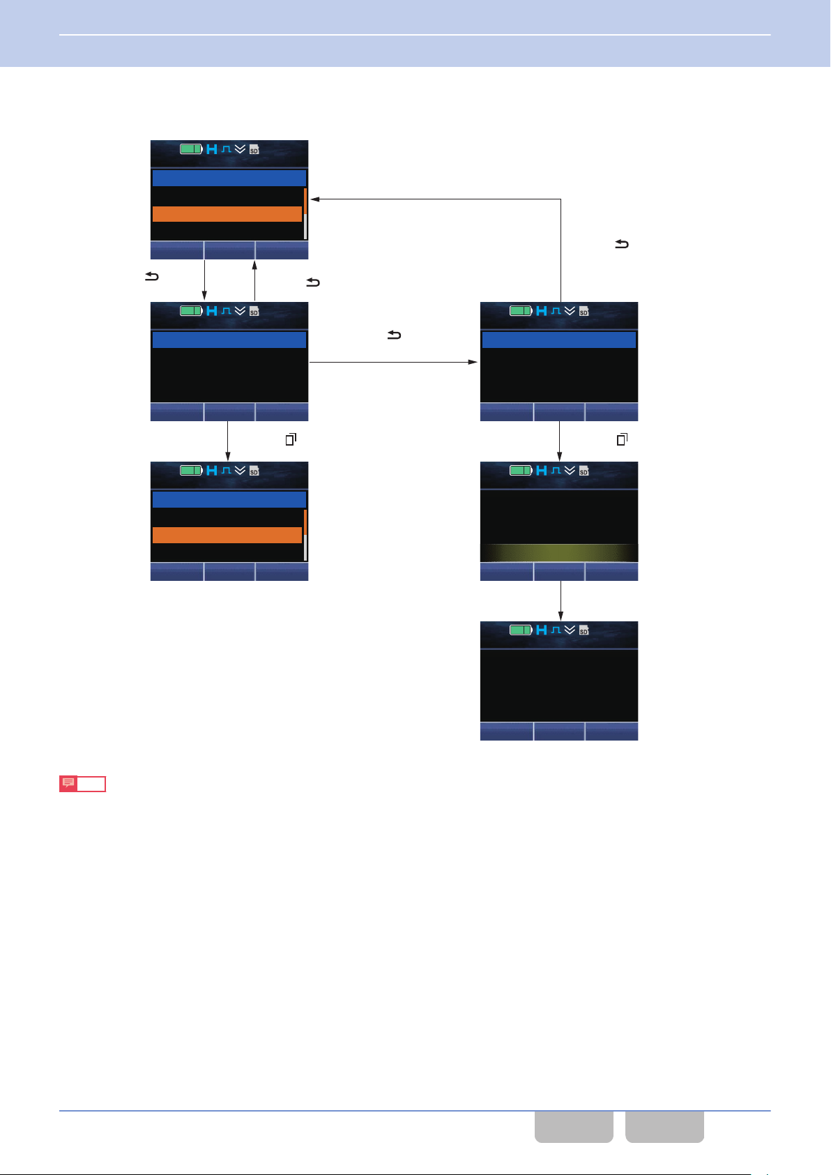
*1
1 second later
Menu ([ ]) or [*] key (OK)
Menu ([ ]) or [*] key (OK)
Play
12 : 34
A
M
01/23/’14 9:23A
01/23/’14 9:35A
01/23/’14 2:20P
Delete
Playback 2
OK
12 : 34
A
M
Delete?
Back
Playback 2
OK
12 : 34
A
M
All Delete?
Back
Playback
All
Play
12 : 34
A
M
01/23/’14 9:23A
01/23/’14 2:20P
01/23/’14 3:30P
Delete
Playback 2
Menu Zone
+
Zone 1
Channel 1
12 : 34
A
M
Empty
Menu Zone
+
Zone 1
Channel 1
12 : 34
A
M
Back ([ ]) or [#] key (Back)
Back ([ ]) or
[#] key (Back)
If pressing and holding
the Back ([ ]) or [#] key
as it stands in*1:
Back ([ ]) or
[#] key (Delete)
3 BASIC OPERATIONS
3.8 Operating the Transceiver in Each Mode (Common Operation)
Clearing data from a list
0
The following are the operation examples for clearing recorded data in Playback Mode:
Note
The following are the main keys to be used for these operation examples:
To clear one piece of data: Press the Back ([O]) or [#] key.
To clear all data: Press and hold the Back ([O]) or [#] key.
To determine: the Menu ([Q]) or [*]
key
Common FUNC (K, F)/Ver 2.20 60
CONTENTS INDEX
Page 92
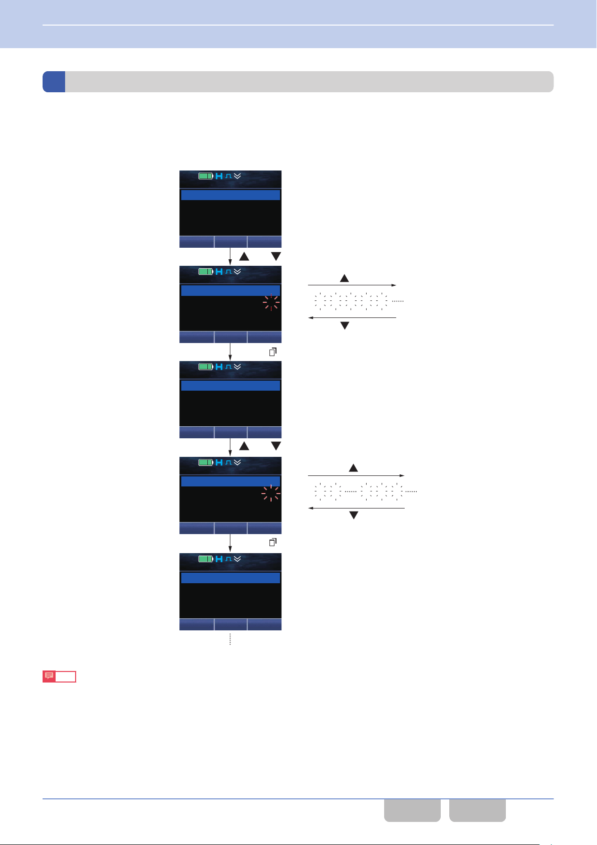
Select "1".
[ ] key
[ ] key
Menu ([ ]) or [*] key (Select)
Select "2".
Menu ([ ]) or [*] key (Select)
12 : 34
A
M
ID
Back
Individual
12 : 34
A
M
Individual
ID 1
DeleteSelect
12 : 34
A
M
Individual
ID 1
DeleteCall
12 : 34
A
M
Individual
ID 10
DeleteSelect
12 : 34
A
M
Individual
ID 12
DeleteCall
[ ] or [ ] key
[ ] or [ ] key
[ ] key
[ ] key
2 3 4 5 6
1 2
9 0 1
3 BASIC OPERATIONS
3.8 Operating the Transceiver in Each Mode (Common Operation)
Entering or Deleting a Code
This section explains operations using operating examples for Individual Call Mode. The displays used in this section are
the displays when Individual Call Acknowledge Request
0
Entering a code using the [G] or [H] key
The following is the operation example to enter “ID 12” in Individual Call Mode:
in an NXDN Conventional system is enabled.
Note
0
The following are the main keys to be used for these operation examples:
To select a code: the [G] or [H] key
To determine: the Menu ([Q]) or [*] key
0
Pressing and holding the [G] or [H] key continuously scrolls the code up or down.
0
The code that can be entered varies depending on the mode and the number of entered digits.
Common FUNC (K, F)/Ver 2.20 61
CONTENTS INDEX
Page 93
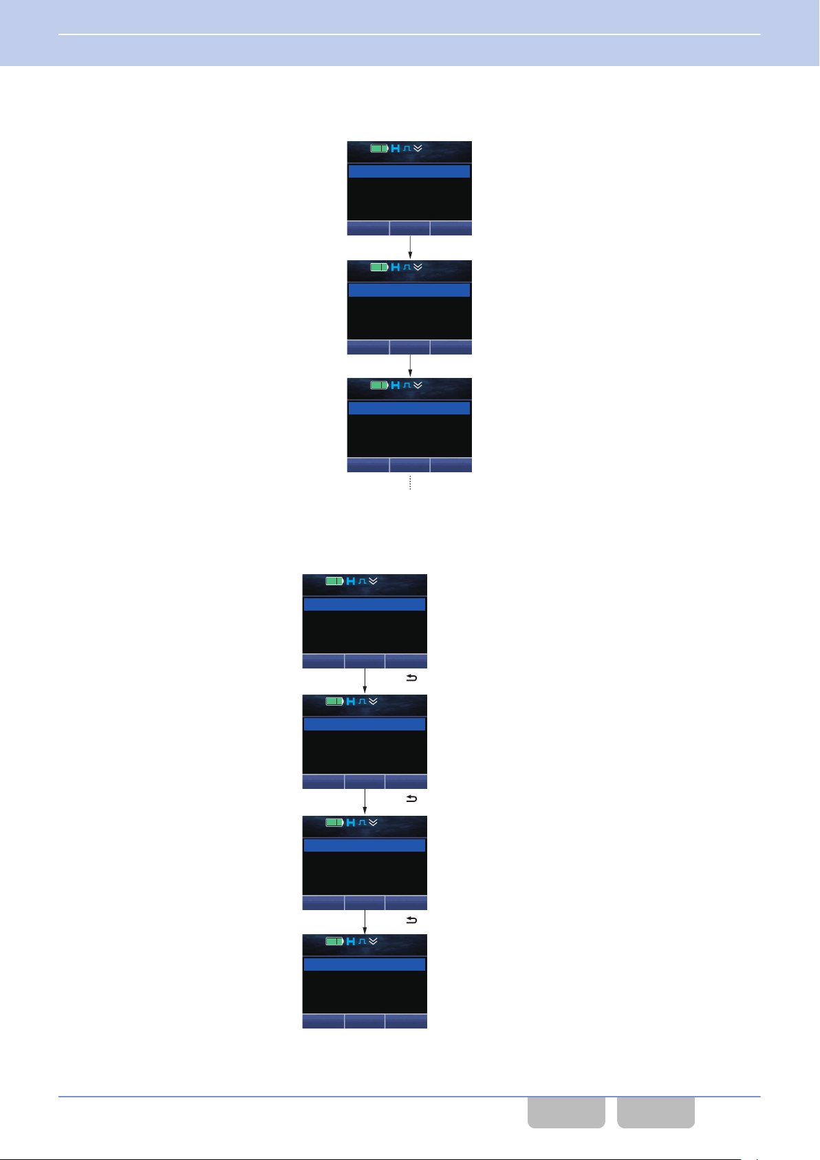
[1] key
[2] key
12 : 34
A
M
Individual
ID
Back
12 : 34
A
M
Individual
ID 1
DeleteCall
12 : 34
A
M
Individual
ID 12
DeleteCall
12 : 34
A
M
Individual
ID 12345
Call Delete
12 : 34
A
M
Individual
ID 1234
DeleteCall
12 : 34
A
M
Individual
ID
123
DeleteCall
12 : 34
A
M
Individual
ID
Back
Back ([ ]) or [#] key (Delete)
Back ([ ]) or [#] key (Delete)
Back ([ ]) or [#] key (Delete)
3 BASIC OPERATIONS
3.8 Operating the Transceiver in Each Mode (Common Operation)
Entering a code using the keypad
0
The following is the operation example to enter “ID 12” in Individual Call Mode:
Deleting the entered code
0
Pressing the Back
held, all the codes are cleared.
([O]) or [#] key clears the lowest digit of the code. If the Back ([O]) or [#] key remains pressed and
Common FUNC (K, F)/Ver 2.20 62
CONTENTS INDEX
Page 94
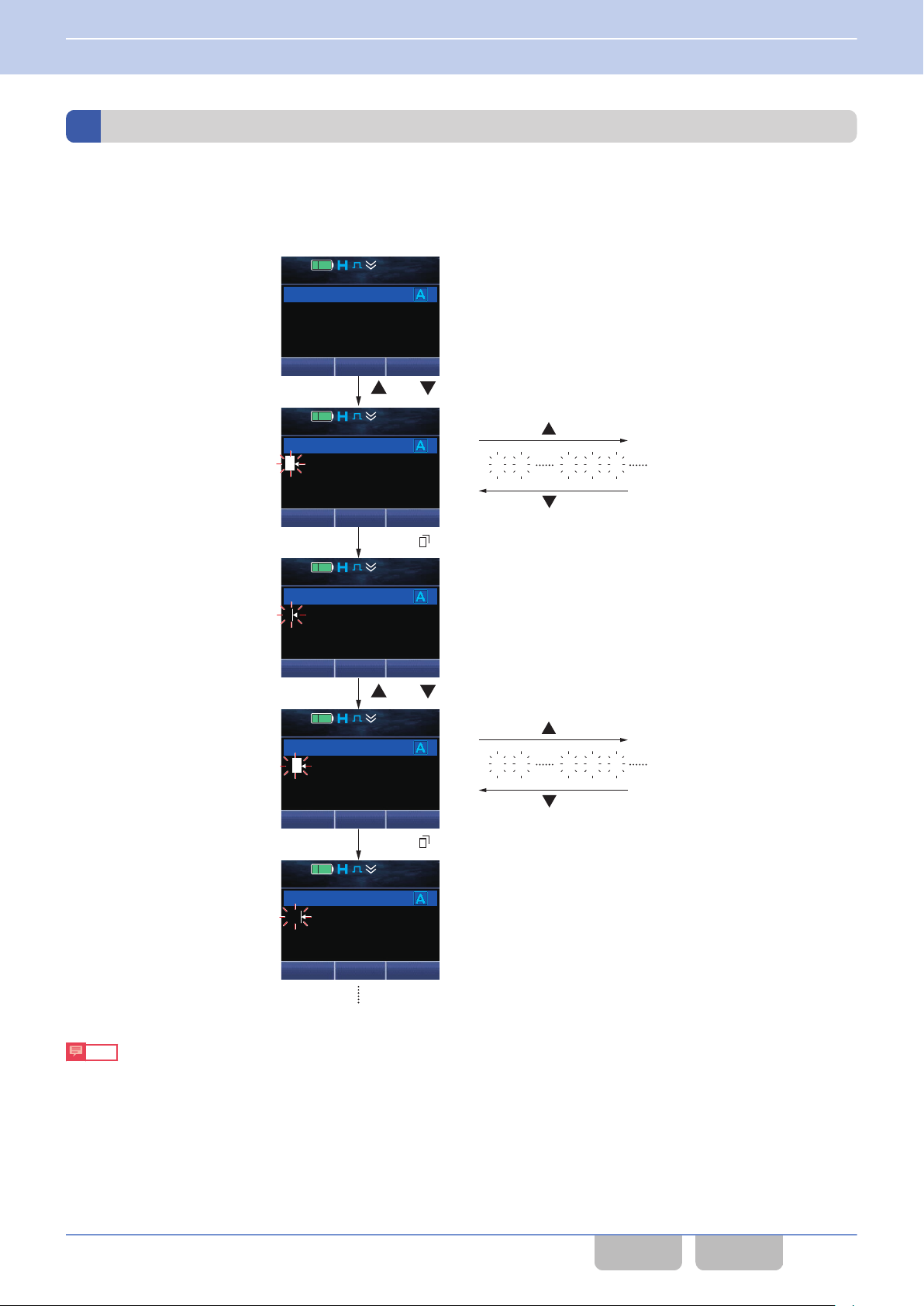
Select "J".
Select "V".
Menu ([ ]) or [*] key (Select)
Menu ([ ]) or [*] key (Select)
12 : 34
A
M
Short Message
Message?
Back
12 : 34
A
M
Short Message
DeleteSelect
A
12 : 34
A
M
Short Message
DeleteSend
J
12 : 34
A
M
Short Message
J
DeleteSelect
J
12 : 34
A
M
Short Message
DeleteSend
JV
[ ] or [ ] key
[ ] or [ ] key
[ ] key
[ ] key
B C
8 9 A
[ ] key
[ ] key
L M
8 9
A
3 BASIC OPERATIONS
3.8 Operating the Transceiver in Each Mode (Common Operation)
Entering or Deleting Characters
This section explains operations using operating examples for Short Message Mode.
0
Entering characters using the [G] and [H] keys
The following is the operation example to enter “JVC” in Short Message Mode.
0
Note
The following are the main keys to be used for these operation examples:
0
0
0
Common FUNC (K, F)/Ver 2.20 63
To select a character: the [G] or [H] key
To determine: the Menu ([Q]) or [*] key
Pressing and holding the [G] or [H] key scrolls the character up or down.
Characters to be entered can be changed by the configuration in Character Entry. (Refer to Character Entry.)
E at the end of the entered string of text is the mark indicating the end position.
CONTENTS INDEX
Page 95
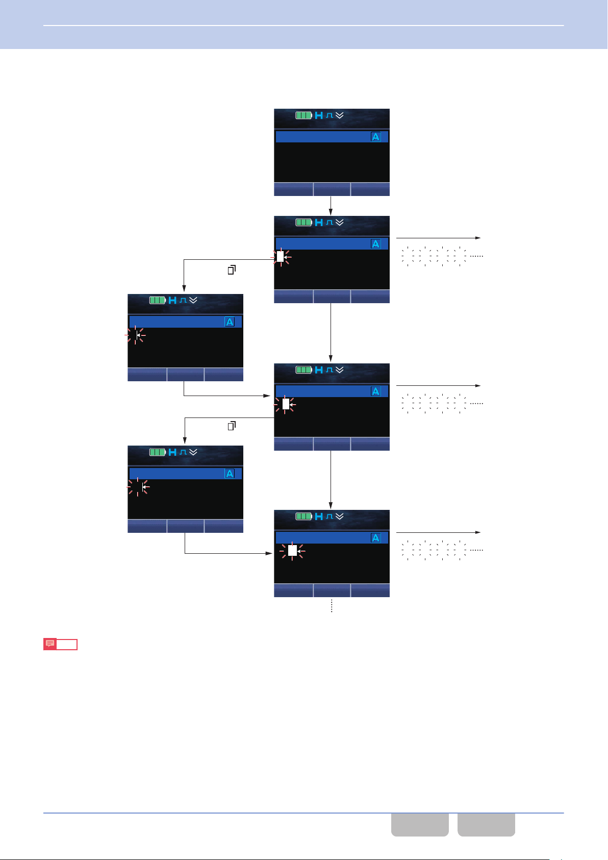
[5] key
[6] key
[3] key
[3] key
[6] key
Select "K".
Select "K".
Select "E".
Select "E".
[5] key
[3] key
Menu ([ ]) or
[*] key (Select)
Menu ([ ]) or
[*] key (Select)
12 : 34
A
M
Short Message
Message?
Back
12 : 34
A
M
Short Message
DeleteSelect
J
12 : 34
A
M
Short Message
DeleteSend
K
12 : 34
A
M
Short Message
K
DeleteSelect
D
12 : 34
A
M
Short Message
DeleteSend
KE
12 : 34
A
M
Short Message
DeleteSend
KEM
J K L J
D E F D
[6] key
M N O M
3 BASIC OPERATIONS
3.8 Operating the Transceiver in Each Mode (Common Operation)
Entering characters using the keypad
0
The following is the operation example to enter “KENWOOD” in Short Message Mode.
0
The following are the main keys to be used for these operation examples:
0
Characters to be entered can be changed by the configuration in Character Entry. (Refer to Character Entry.)
Note
To select a character: each key on the keypad
To determine: the Menu ([Q]) or [*] key
Common FUNC (K, F)/Ver 2.20 64
CONTENTS INDEX
Page 96
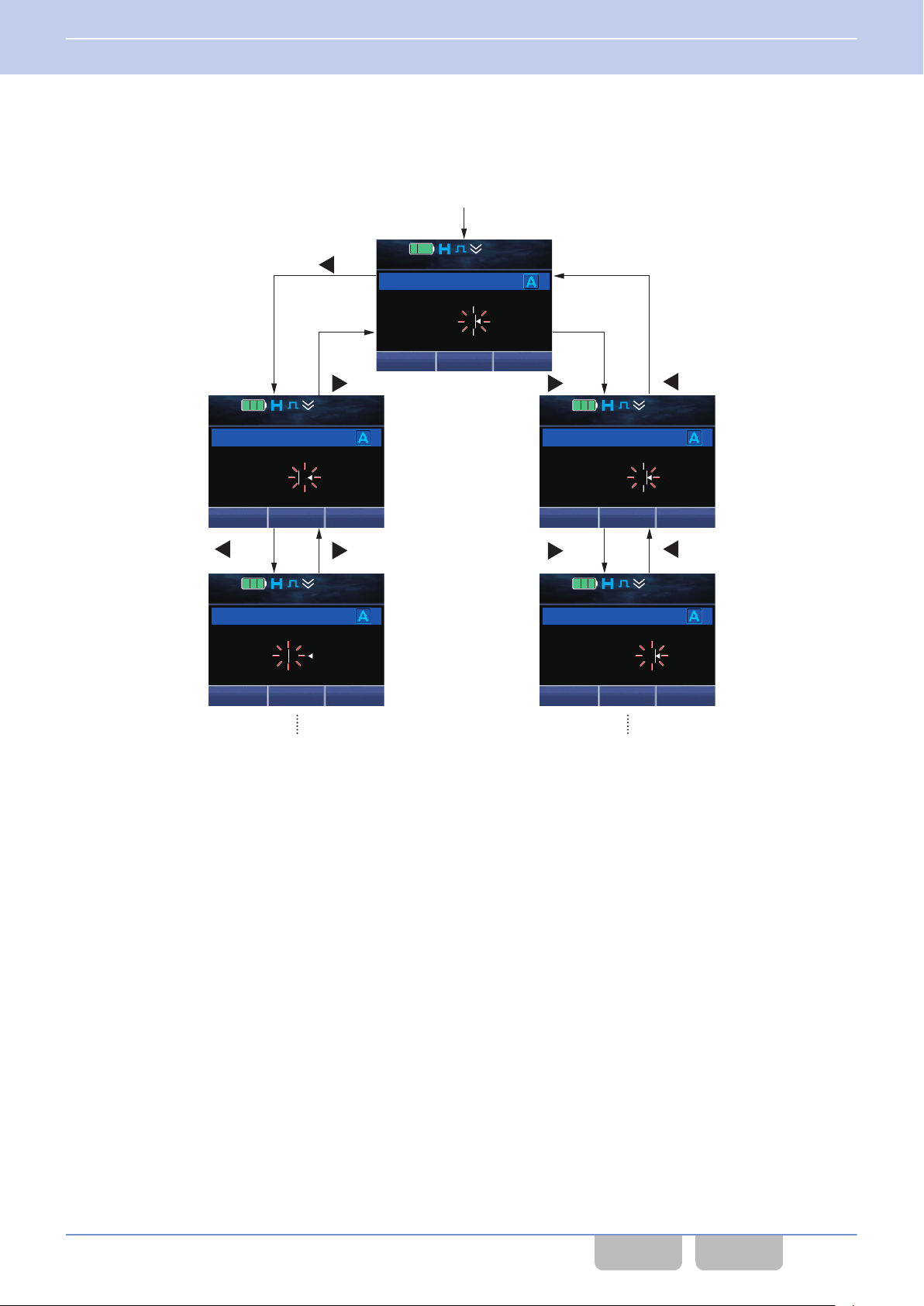
Enter "JVCKENWOOD"
12 : 34
A
M
Short Message
DeleteSend
JVCKENWOOD
12 : 34
A
M
Short Message
DeleteSend
JVCKENWOOD
12 : 34
A
M
Short Message
DeleteSend
JVCKENWOOD
12 : 34
A
M
Short Message
DeleteSend
JVCKENWOOD
12 : 34
A
M
Short Message
DeleteSend
JVCKENWOOD
[ ] key
[ ] key
[ ] key[ ] key[ ] key
[ ] key
[ ] key[ ] key
3 BASIC OPERATIONS
3.8 Operating the Transceiver in Each Mode (Common Operation)
Moving the cursor
0
Pressing the [E] key moves the cursor to left, and pressing the [F] key moves the cursor to right. Pressing and holding
the [E] or [F] key moves the cursor continuously.
Common FUNC (K, F)/Ver 2.20 65
CONTENTS INDEX
Page 97
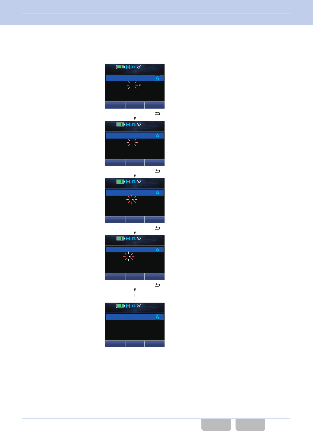
12 : 34
A
M
Short Message
DeleteSend
JVCKENWOOD
12 : 34
A
M
Short Message
DeleteSend
JVCKENWOD
12 : 34
A
M
Short Message
DeleteSend
JVCKENWO
12 : 34
A
M
Short Message
DeleteSend
JVCKENW
12 : 34
A
M
Short Message
Message?
Back
Back ([ ]) or [#] key (Delete)
Back ([ ]) or [#] key (Delete)
Back ([ ]) or [#] key (Delete)
Back ([ ]) or [#] key (Delete)
3 BASIC OPERATIONS
3.8 Operating the Transceiver in Each Mode (Common Operation)
Deleting characters
0
Pressing
the Back ([O]) or [#] key deletes one character. If the Back ([O]) or [#] key remains pressed and held, all the
characters are deleted.
Common FUNC (K, F)/Ver 2.20 66
CONTENTS INDEX
Page 98
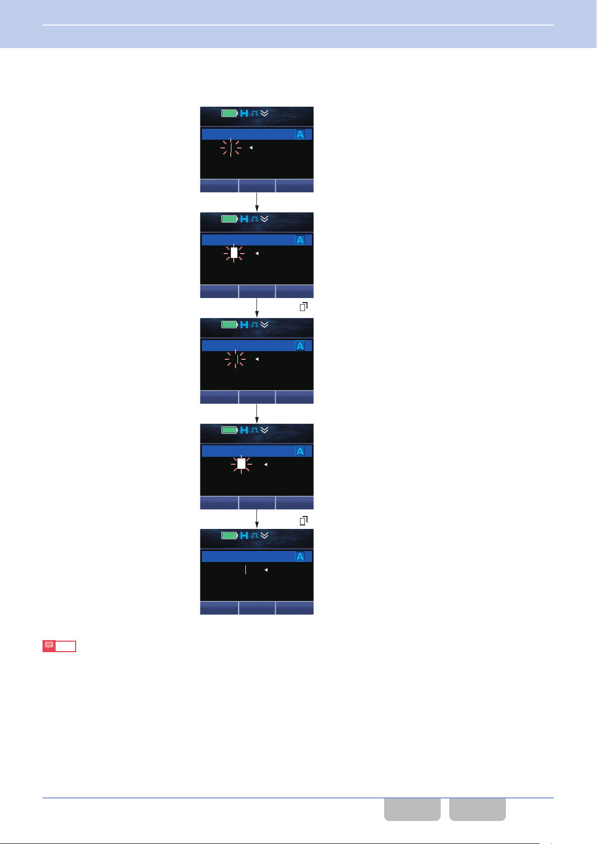
Press the [6] key twice.
[9] key
Menu ([ ]) or [*] key (Select)
Menu ([ ]) or [*] key (Select)
12 : 34
A
M
Short Message
DeleteSend
JVCKE0OD
12 : 34
A
M
Short Message
DeleteSelect
JVCKEN0OD
12 : 34
A
M
Short Message
DeleteSend
JVCKEN0OD
12 : 34
A
M
Short Message
DeleteSelect
JVCKENW0OD
12 : 34
A
M
Short Message
DeleteSend
JVCKENW0OD
3 BASIC OPERATIONS
3.8 Operating the Transceiver in Each Mode (Common Operation)
Inserting characters
0
The following is the operation example to correct “JVCKEOOD” to “JVCKENWOOD” in Short Message Mode.
0
0
Note
The following are the main keys to be used for these operation examples:
To select a character: each key on the keypad
To determine: the Menu ([Q]) or [*] key
Characters to be entered can be changed by the configuration in Character Entry. (Refer to Character Entry.)
Common FUNC (K, F)/Ver 2.20 67
CONTENTS INDEX
Page 99
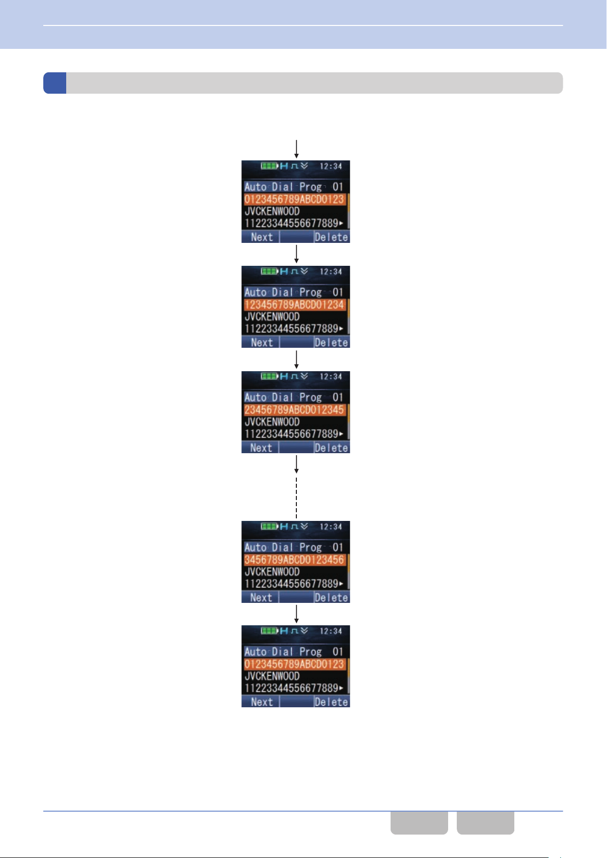
A
utodial Programming Mode
1 second late
r
1 second late
r
200 ms later
200 ms later
3 BASIC OPERATIONS
3.8 Operating the Transceiver in Each Mode (Common Operation)
Scroll Display
An example of the display of DTMF code (0123456789ABCD0123456789ABCD) is as follows:
Common FUNC (K, F)/Ver 2.20 68
CONTENTS INDEX
Page 100
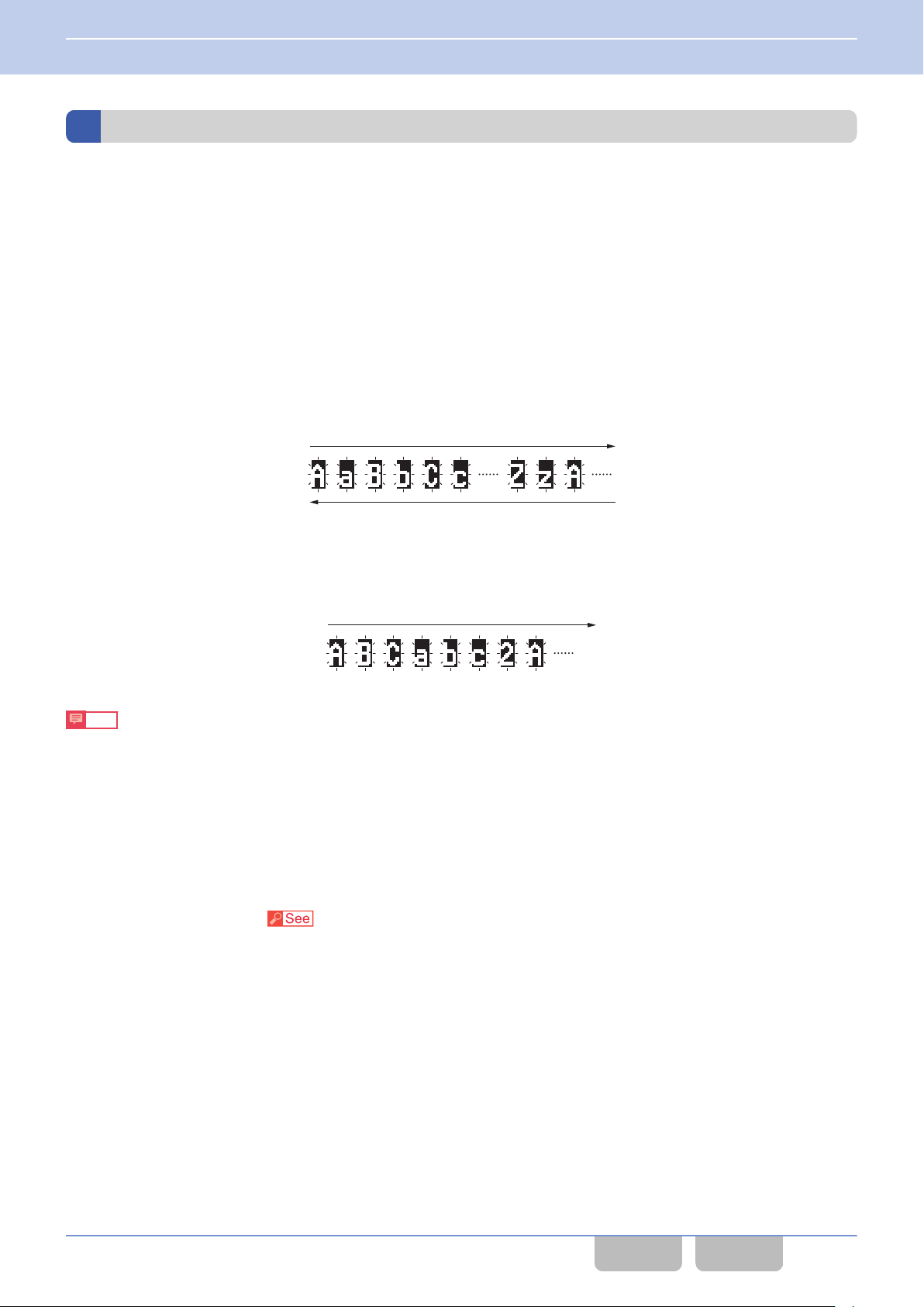
Each time the Up key is pressed, a focused letter varies
in the predetermined order.
Each time the Down key is pressed, a focused letter varies
in the opposite order to the predetermined order.
Each time the [2] key is pressed, a focused letter varies
in the predetermined order.
3 BASIC OPERATIONS
3.8 Operating the Transceiver in Each Mode (Common Operation)
Character Entry
Character Entry is the function to enter alphanumeric characters and symbols by using the [0] to[9], [G], or [H] key.
Symbols and lower-case characters can be entered by using the [0] to [9], [G], or [H] key on the keypad. The number of
key operations for entering characters can be minimized by configuring only necessary characters.
A maximum of 16 alphanumeric characters and symbols, namely 8 characters of Capital Font and 8 characters of Small
Font, can be configured for each of the [0] to [9] keys on the keypad.
A maximum of 80 alphanumeric characters and symbols can be configured for the [G] or [H] key on the keypad.
Character Entry can be used to enter a message in Short Message Mode.
Operating the Transceiver (Operation Examples for Portable)
If “AaBbCc...Zz” is configured for the Up and Down keys
0
If “ABCabc2” is configured for the [2] key
0
Note
0
When the Function
Uppercase characters > lowercase characters > numbers > uppercase characters ...
0
If the behavior of the [G]/ [H] key is configured “Line Up/Down”, the [G]/ [H] key can be used to move the cursor up
and down and characters cannot be entered.
0
Refer to “Operating the Transceiver in Each Mode (Common Operation)” for operation methods.
([W]) or [*] key is pressed, the entry mode switches as follows:
Configuration using KPG-D1/ D1N
Configuring Character Entry (
Transceiver Settings > Key Assignment > Character Entry)
Common FUNC (K, F)/Ver 2.20 69
CONTENTS INDEX
 Loading...