

Kenwood NX-3720, NX-3820, NX-3720G, NX-3820G User Manual

.
NX-3000 series
USER GUIDE
GUIDE DE L’UTILISATEUR
GUÍA DEL USUARIO
GUIDA PER L’UTENTE
BENUTZERHANDBUCH
GEBRUIKERSHANDLEIDING
KULLANICI REHBERI
ΟΔΗΓΟΣ ΧΡΗΣΤΗ
GUIA DO UTILIZADOR
.
.
.
B5A-1680-00 (E)

Importeur
Amsterdamseweg 37, 1422 AC Uithoorn, Nederland
Importer
12 Priestley Way, London NW2 7BA, United Kingdom
Importeur
Konrad-Adenauer-Allee 1-11, 61118 Bad Vilbel, Deutschland
Importador
Carretera de Rubi, 88 Planta 1A, 08174 Sant Cugat del Vallès Barcelona, España
Importateur
7 Allee des Barbanniers 92230 Gennevilliers, France
Importatore
Via G. Sirtori 7/9, 20129 Milano, Italia
Importeur
Leuvensesteenweg 248J, 1800 Vilvoorde, België
Authorised Representative in Europe
Amsterdamseweg 37, 1422 AC Uithoorn, THE NETHERLANDS
Manufacturer
3-12 Moriyacho, Kanagawa-ku, Yokohama-shi, Kanagawa, 221-0022, JAPAN

VHF DIGITAL TRANSCEIVER
NX-3720
NX-3720G
UHF DIGITAL TRANSCEIVER
NX-3820
NX-3820G
USER GUIDE
.
This User Guide covers only the basic operations of your radio. Ask your dealer for
information on any customized features they may have added to your radio. For using
details User Manual, refer to the following URL.
http://manual.kenwood.com/en_contents/search/keyword
.
●
The Bluetooth® word mark and logo are registered trademarks owned by Bluetooth SIG, Inc.
and any use of such marks by JVC KENWOOD Corporation is under license. Other
trademarks and trade names are those of their respective owners.
.
NOTIFICATION
This equipment complies with the essential requirements of Directive 2014/53/EU.
This equipment requires a licence and is intended for use in the countries as below.
AT BE DK FI FR DE GR IS IE IT LI LU
NL NO PT ES SE CH GB CY CZ EE HU LV
LT MT PL SK SI BG RO HR TR
ISO3166

THANK YOU
We are grateful you have chosen KENWOOD for your Digital Transceiver
applications.
CONTENTS
NOTICES TO THE USER ............................................................................................................ 3
PRECAUTIONS ........................................................................................................................... 4
UNPACKING AND CHECKING EQUIPMENT ............................................................................ 5
SUPPLIED ACCESSORIES ...................................................................................................... 5
PREPARATION ........................................................................................................................... 6
ORIENTATION ............................................................................................................................ 8
OPERATION PANEL ................................................................................................................. 8
DISPLAY ................................................................................................................................... 9
BASIC OPERATIONS ............................................................................................................... 12
SWITCHING POWER ON/ OFF .............................................................................................. 12
ADJUSTING THE VOLUME .................................................................................................... 12
SELECTING A ZONE AND CHANNEL ................................................................................... 12
TRANSMITTING ..................................................................................................................... 12
RECEIVING ............................................................................................................................. 12
INFORMATION ON SOFTWARE LICENSE ............................................................................. 13
2

NOTICES TO THE USER
●
Government law prohibits the operation of unlicensed radio transmitters within the territories under
government control.
●
Illegal operation is punishable by fine and/or imprisonment.
●
Refer service to qualified technicians only.
Safety: It is important that the operator is aware of, and understands, hazards
common to the operation of any transceiver.
WARNING
●
EXPLOSIVE ATMOSPHERES (GASES, DUST, FUMES, etc.)
Turn OFF your transceiver while taking on fuel or while parked in gasoline service stations. Do not
carry spare fuel containers in the trunk of your vehicle if your transceiver is mounted in the trunk
area.
●
INJURY FROM RADIO FREQUENCY TRANSMISSIONS
Do not operate your transceiver when somebody is either standing near to or touching the antenna,
to avoid the possibility of radio frequency burns or related physical injury.
●
DYNAMITE BLASTING CAPS
Operating the transceiver within 500 feet (150 m) of dynamite blasting caps may cause them to
explode. Turn OFF your transceiver when in an area where blasting is in progress, or where “TURN
OFF TWO-WAY RADIO” signs have been posted. If you are transporting blasting caps in your
vehicle, make sure they are carried in a closed metal box with a padded interior. Do not transmit
while the caps are being placed into or removed from the container.
.
The AMBE+2™ voice coding Technology embodied in this product is protected by intellectual property
rights including patent rights, copyrights and trade secrets of Digital Voice Systems, Inc. This voice
coding Technology is licensed solely for use within this Communications Equipment. The user of this
Technology is explicitly prohibited from attempting to extract, remove, decompile, reverse engineer, or
disassemble the Object Code, or in any other way convert the Object Code into a human-readable form.
U.S. Patent Nos. #8,315,860, #8,595,002, #6,199,037, #6,912,495, #8,200,497, #7,970,606 and
#8,359,197
Firmware Copyrights
The title to and ownership of copyrights for firmware embedded in KENWOOD product memories are
reserved for JVC KENWOOD Corporation.
.
Information on Disposal of Old Electrical and Electronic Equipment and Batteries (applicable for
countries that have adopted separate waste collection systems)
.
Products and batteries with the symbol (crossed-out wheeled bin) cannot be
disposed as household waste.
Old electrical and electronic equipment and batteries should be recycled at a facility
capable of handling these items and their waste byproducts.
Contact your local authority for details in locating a recycle facility nearest to you.
Proper recycling and waste disposal will help conserve resources whilst preventing
detrimental effects on our health and the environment.
3
PRECAUTIONS
Observe the following precautions to prevent fire, personal injury, and transceiver
damage.
●
Do not attempt to configure the transceiver while driving; it is too dangerous.
●
Do not disassemble or modify the transceiver for any reason.
●
Do not expose the transceiver to long periods of direct sunlight, nor place it near heating appliances.
●
If an abnormal odor or smoke is detected coming from the transceiver, switch the transceiver power
off immediately, and contact your KENWOOD dealer.
●
Use of the transceiver while you are driving may be against traffic laws. Please check and observe the
vehicle regulations in your area.
●
Do not use options not specified by KENWOOD.
●
Do not put the plastic bag used for packing of this equipment on the place which reaches a small child's
hand. It will become a cause of suffocation if it wears flatly.
●
Do not place the transceiver on unstable surfaces.
●
Keep the volume as low as possible to protect your hearing.
●
Always switch the transceiver power off before installing optional accessories.
●
To dispose of batteries, be sure to comply with the laws and regulations in your country or region.
CAUTION
●
The transceiver operates in 12 V negative ground systems only! Check the battery polarity and
voltage of the vehicle before installing the transceiver.
●
Use only the supplied DC power cable or a KENWOOD optional DC power cable.
●
Do not cut and/or remove the fuse holder on the DC power cable.
●
Do not place the microphone cable around your neck while near machinery that may catch the
cable.
WARNING
●
For passenger safety, install the transceiver securely using the supplied mounting bracket and
screw set so the transceiver will not break loose in the event of a collision.
When using the transceiver, refer to the “NOTICES TO THE USER” and “PRECAUTIONS”. If the
warnings are not observed, there may be possibility of malfunction. In this case, press and hold the Power
Switch for 5 seconds or more. If the malfunction persists, ask your dealer.
4

UNPACKING AND CHECKING EQUIPMENT
Note:
●
The following unpacking instructions are for use by your KENWOOD dealer, an authorized
KENWOOD service facility, or the factory.
Carefully unpack the transceiver. We recommend that you identify the items listed
below before discarding the packing material. If any items are missing or have been
damaged during shipment, file a claim with the carrier immediately.
SUPPLIED ACCESSORIES
DC power cable (with fuses) ................................................................................................ 1
●
15 A fuse ......................................................................................................................... 2
Mounting bracket ................................................................................................................. 1
Screw set
●
5 x 16 mm self-tapping screw ......................................................................................... 4
●
M4 x 6 mm hex-headed screw with washer .................................................................... 4
●
Spring washer ................................................................................................................. 4
●
Flat washer ..................................................................................................................... 4
User Guide ........................................................................................................................... 1
5
PREPARATION
WARNING
Various electronic equipment in your vehicle may malfunction if they are not properly protected from
the radio frequency energy which is present while transmitting. Typical examples include electronic
fuel injection, anti-skid braking, and cruise control. If your vehicle contains such equipment, consult
the dealer for the make of vehicle and enlist his/her aid in determining if they will perform normally
while transmitting.
o
Connecting the power cable
CAUTION
The transceiver operates in 12 V negative ground systems only! Check the battery polarity and voltage
of the vehicle before installing the transceiver.
1
Check for an existing hole, conveniently located in the firewall, where the power
cable can be passed through.
●
If no hole exists, use a circle cutter to drill a hole, then install a rubber grommet.
2
Run the power cable through the firewall and into the engine compartment.
3
Connect the red lead to the positive (+) battery terminal and the black lead to the
negative (–) battery terminal.
●
Place the fuse as close to the battery as possible.
4
Coil the surplus cable and secure it with a retaining band.
●
Be sure to leave enough slack in the cables so the transceiver can be removed for
servicing while keeping the power applied.
o
Installing the transceiver
WARNING
For passenger safety, install the transceiver securely using the supplied mounting bracket and screw
set, so the transceiver will not break loose in the event of a collision.
Note:
●
Before installing the transceiver, check how far the mounting screws will extend below the
surface. When drilling mounting holes, be careful not to damage vehicle wiring or parts.
1
Mark the position of the holes in the dash, using the mounting bracket as a
template. Using a 4.2 mm (5/32 inch) drill bit, drill the holes, then attach the
mounting bracket using the supplied screws.
●
Mount the transceiver within easy reach of the user and where there is sufficient space
at the rear of the transceiver for cable connections.
2
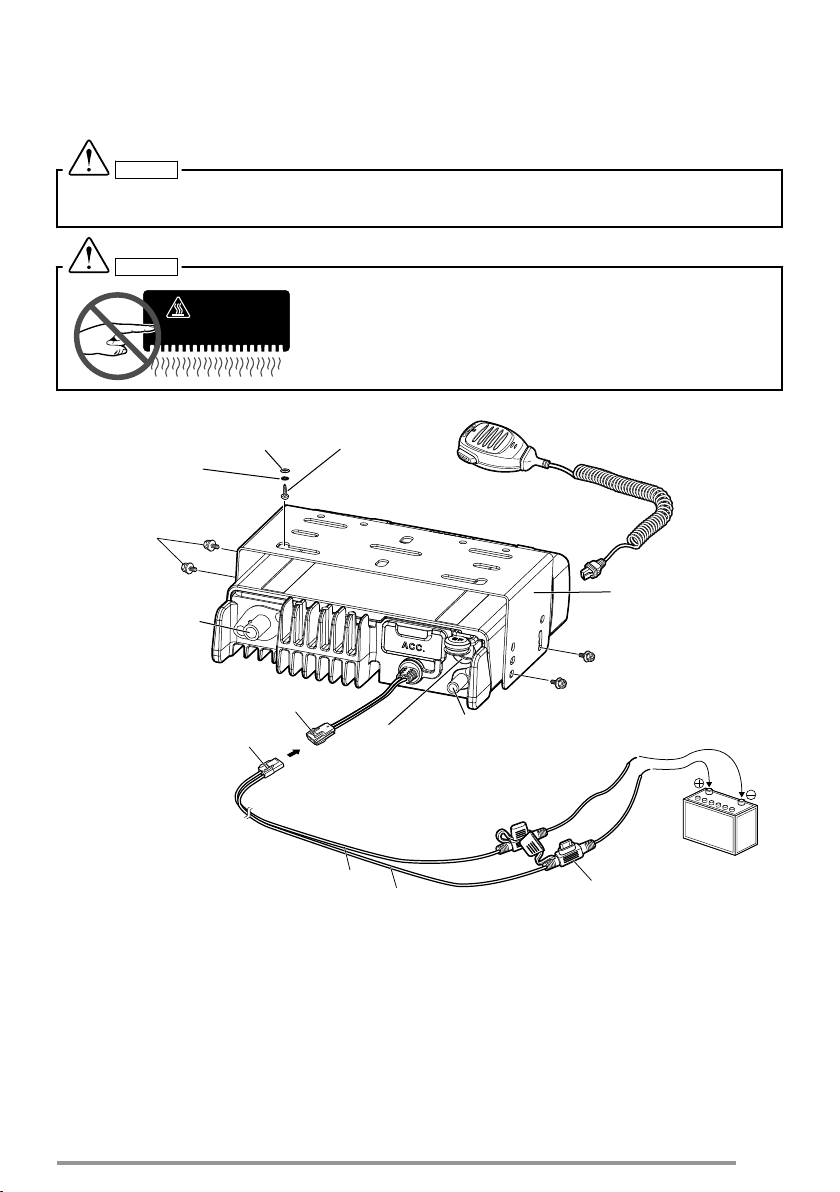
Connect the antenna and the supplied power cable to the transceiver.
3
Slide the transceiver into the mounting bracket and secure it using the supplied
hex-headed screws.
6
4
HOT SURFACE
5 x 16 mm
Self-tapping
screw
Flat washer
Spring washer
M4 x 6 mm
hex-headed
screw with
washer
RF antenna
connector
External
speaker jack
Black (–) cable
Red (+) cable
Fuse
12 V vehicle
battery
Mounting bracket
DC power cable
Power input connector
Optional microphone
GPS antenna connector for KRA-40
(NX-3720G/ NX-3820G only)
Mount the microphone hanger in a location where it will be within easy reach of
the user.
●
The microphone and microphone cable should be mounted in a place where they will
not interfere with the safe operation of the vehicle.
CAUTION
When replacing the fuse in the DC power cable, be sure to replace it with a fuse of the same rating.
Never replace a fuse with one that is rated with a higher capacity.
CAUTION
.
Do not touch the metal surface of the transceiver while it is in use.
Do not mount the transceiver such that the chassis can come in
contact with skin.
High temperatures may burn your skin.
7
ORIENTATION
AC
G
E
FD
B
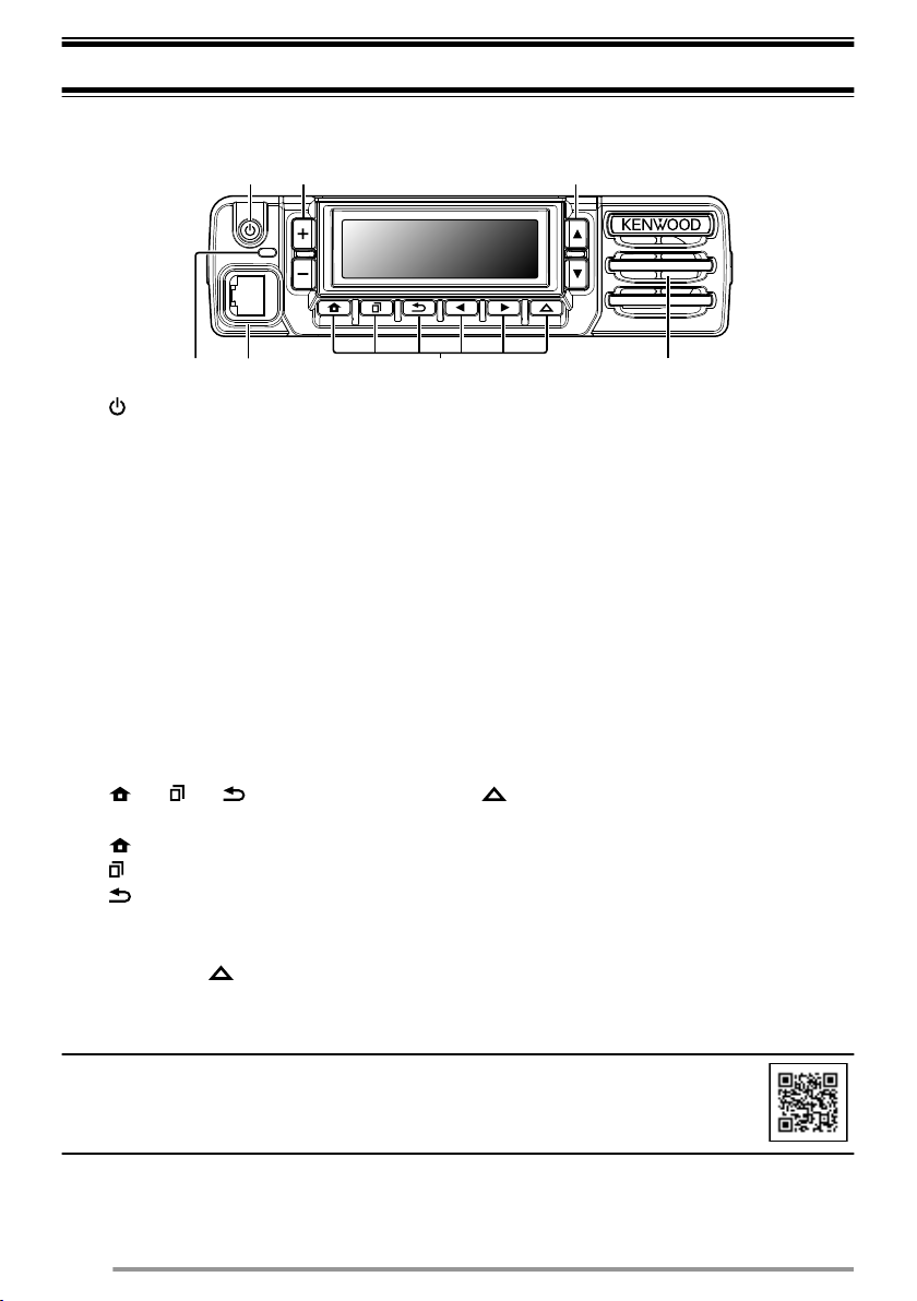
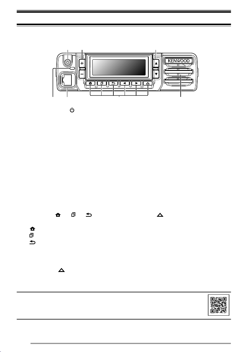
OPERATION PANEL
A
[ ] (Power) switch
Press to switch the transceiver ON or OFF.
B
[+] / [-] buttons
Press to activate their programmable functions. The default button setting is
[Volume Up]/ [Volume Down].
C
[J]/ [K] buttons
Press to activate their programmable functions. The default button setting is
[Channel Up]/ [Channel Down].
D
TX/RX indicator
The indicator lights in different colors to indicate the current status of the
transceiver.
Lights red while transmitting and green while receiving.
E
Microphone jack
Insert the microphone plug into this jack.
F
[ ] / [ ] / [ ] / [H] / [I] / Auxiliary ( ) buttons
Press to activate their programmable functions.
] : The default button setting is [Clear].
[
[ ] : The default button setting is [Menu].
[ ] : The default button setting is [Squelch Off Momentary].
[H] : The default button setting is [Zone Down].
[I] : The default button setting is [Zone Up].
Auxiliary (
G
Speaker
Internal speaker.
.
For details on programming functions to the buttons on your transceiver, please contact your
dealer or refer to the “User Manual” available from the following URL.
http://manual.kenwood.com/en_contents/search/keyword
.
) : The default button setting is [None].
8
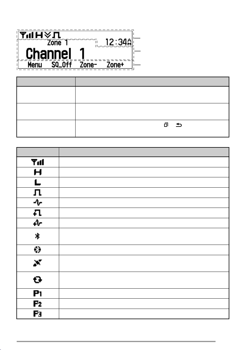
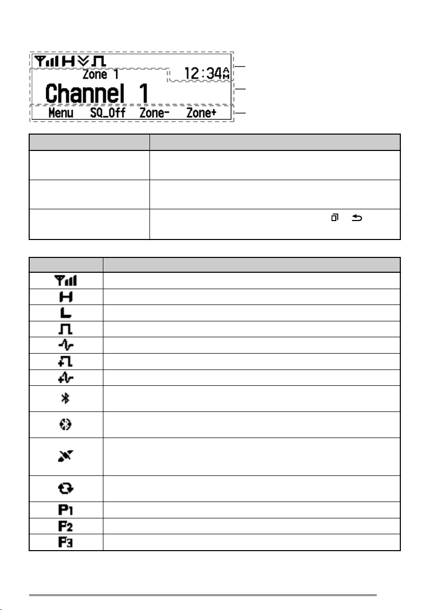
DISPLAY
Main Area
Function Indicator Area
Button Guide Area
Basic Frame
Display Area Description
Function Indicator
Area
Main Area
Button Guide Area
Function Indicator
Indicator Description
Displays the various function indicators, signal strength
indicator and clock.
Displays the information of the transceiver such as Channel
number and Zone number.
Displays the button functions for [ ], [ ], [H] and [I]
buttons.
Displays the signal strength.
The channel is using high transmit power.
The channel is using low transmit power.
In Digital mode (Digital Channel)
In Analog mode (Analog Channel)
In Digital mode (Mixed Channel)
In Analog mode (Mixed Channel)
The Bluetooth function is activated. Blinks in the process of turning
on Bluetooth. (NX-3720G/ NX-3820G only)
Connected to a Bluetooth device. (NX-3720G/ NX-3820G only)
The GPS position is determined. Blinks when the GPS is unable
to determine the position. (NX-3720G/ NX-3820G only)
Scan, Priority Scan or Voting/ Site Roaming is in progress. Blinks
when the scan is paused.
Indicates Priority channel 1 or Priority Monitor ID 1.
Indicates Priority channel 2 or Priority Monitor ID 2.
Indicates Priority Monitor ID 3.
9
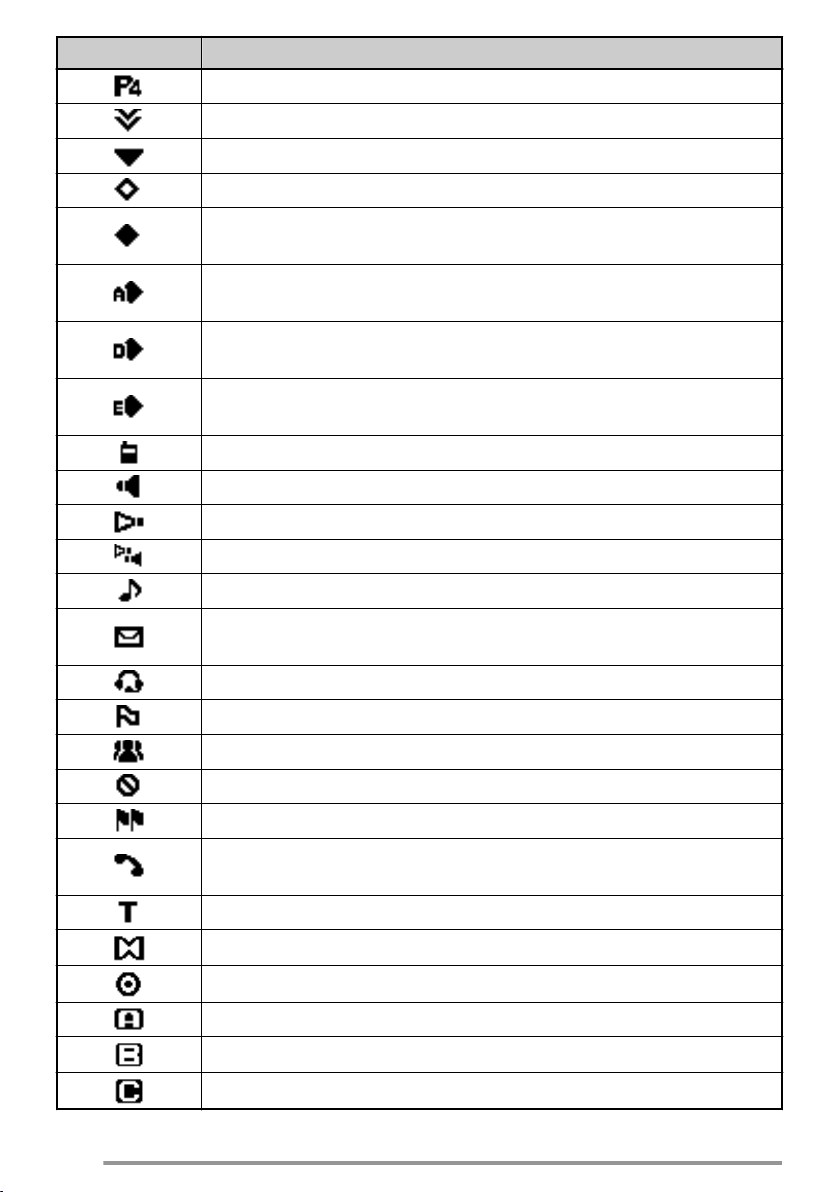
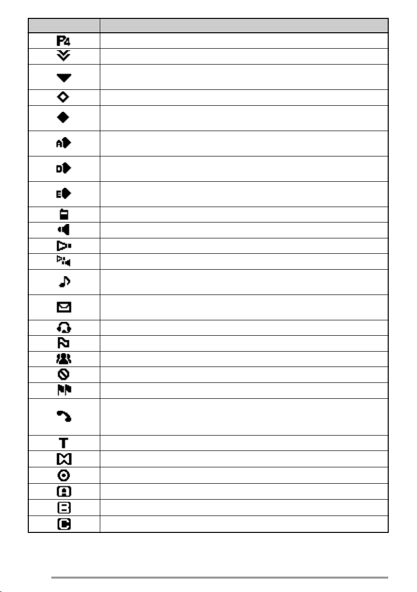
Indicator Description
Indicates Priority Monitor ID 4.
The current channel is added to the scanning sequence.
The current zone is added to the Multi-Zone scanning sequence.
The Scrambler function is activated.
The Encryption function is activated. Blinks when receiving an
encrypted carrier.
The Encryption (AES) function is activated. Blinks when receiving
an encrypted carrier.
The Encryption (DES) function is activated. Blinks when receiving
an encrypted carrier.
The Encryption (ARC4) function is activated. Blinks when
receiving an encrypted carrier.
The Talk Around function is activated.
The Monitor or Squelch Off function is activated.
The External Speaker is activated.
The External Speaker (Internal + External) is activated.
Blinks when an incoming call matches your Optional Signaling.
A message is stored in the memory. Blinks when a new message
is received.
The VOX function is activated. (NX-3720G/ NX-3820G only)
10
The Site Lock function is activated.
The Broadcast Call function is activated.
The Surveillance function is activated.
The System Lock function is activated.
Appears when the selected group is programmed as telephone
IDs. Blinks during Auto Telephone search.
The Tactical Zone is activated.
The Horn Alert function is activated.
The Public Address function is activated.
AUX A is activated.
AUX B is activated.
AUX C is activated.

Indicator Description
The Lone Worker function is activated.
The OVCM function is activated.
The Operator Selectable Tone function is activated.
Blinks during Auto Recording.
11

BASIC OPERATIONS
SWITCHING POWER ON/ OFF
Press [ ] to switch the transceiver ON.
Press [
ADJUSTING THE VOLUME
Press the button programmed as [Volume Up] to increase the volume. Press the
button programmed as [Volume Down] to decrease the volume.
SELECTING A ZONE AND CHANNEL
Select the desired zone and channel using the buttons programmed as [Zone Up]/
[Zone Down] and [Channel Up]/ [Channel Down].
●
●
TRANSMITTING
1
2
RECEIVING
Select the desired zone and channel. If signaling has been programmed on the
selected channel, you will hear a call only if the received signal matches your
transceiver settings.
] again to switch the transceiver OFF.
The transceiver may have names programmed for zones and channels. The zone name
and channel name can contain up to 14 characters. While selecting a zone, the zone name
will appear above the channel name.
If programmed by your dealer, your transceiver will announce the zone and channel
numbers as you change them.
Select the desired zone and channel.
Press the PTT switch and speak into the microphone. Release the PTT switch to
receive.
●
The LED indicator lights red while transmitting and green while receiving a signal. This
indicator can also be disabled by your dealer.
●
For best sound quality at the receiving station, hold the microphone approximately 1.5
inches (3 cm to 4 cm) from your mouth.
12

INFORMATION ON SOFTWARE LICENSE
This transceiver uses a software according to the following license agreements.
*zlib LICENSE
Copyright (C) 1995-2013 Jean-loup Gailly and Mark Adler
This software is provided 'as-is', without any express or implied warranty. In no event will the authors be
held liable for any damages arising from the use of this software.
Permission is granted to anyone to use this software for any purpose, including commercial applications,
and to alter it and redistribute it freely, subject to the following restrictions:
1. The origin of this software must not be misrepresented; you must not claim that you wrote the
original software. If you use this software in a product, an acknowledgment in the product
documentation would be appreciated but is not required.
2. Altered source versions must be plainly marked as such, and must not be misrepresented as
being the original software.
3. This notice may not be removed or altered from any source distribution.
Jean-loup Gailly (jloup@gzip.org)
Mark Adler (madler@alumni.caltech.edu)
*libpng LICENSE
This copy of the libpng notices is provided for your convenience. In case of any discrepancy between this
copy and the notices in the file png.h that is included in the libpng distribution, the latter shall prevail.
COPYRIGHT NOTICE, DISCLAIMER, and LICENSE:
If you modify libpng you may insert additional notices immediately following this sentence.
This code is released under the libpng license.
libpng versions 1.2.6, August 15, 2004, through 1.6.8, December 19, 2013, are Copyright (c) 2004,
2006-2013 Glenn Randers-Pehrson, and are distributed according to the same disclaimer and license as
libpng-1.2.5 with the following individual added to the list of Contributing Authors
Cosmin Truta
libpng versions 1.0.7, July 1, 2000, through 1.2.5 - October 3, 2002, are Copyright (c) 2000-2002 Glenn
Randers-Pehrson, and are distributed according to the same disclaimer and license as libpng-1.0.6 with
the following individuals added to the list of Contributing Authors
Simon-Pierre Cadieux
Eric S. Raymond
Gilles Vollant
and with the following additions to the disclaimer:
There is no warranty against interference with your enjoyment of the library or against infringement.
There is no warranty that our efforts or the library will fulfill any of your particular purposes or needs.
This library is provided with all faults, and the entire risk of satisfactory quality, performance, accuracy,
and effort is with the user.
libpng versions 0.97, January 1998, through 1.0.6, March 20, 2000, are Copyright (c) 1998, 1999 Glenn
Randers-Pehrson, and are distributed according to the same disclaimer and license as libpng-0.96, with
the following individuals added to the list of Contributing Authors:
Tom Lane
Glenn Randers-Pehrson
Willem van Schaik
libpng versions 0.89, June 1996, through 0.96, May 1997, are Copyright (c) 1996, 1997 Andreas Dilger
Distributed according to the same disclaimer and license as libpng-0.88, with the following individuals
added to the list of Contributing Authors:
John Bowler
Kevin Bracey
Sam Bushell
Magnus Holmgren
Greg Roelofs
Tom Tanner
13

libpng versions 0.5, May 1995, through 0.88, January 1996, are Copyright (c) 1995, 1996 Guy Eric
Schalnat, Group 42, Inc.
For the purposes of this copyright and license, “Contributing Authors” is defined as the following set of
individuals:
Andreas Dilger
Dave Martindale
Guy Eric Schalnat
Paul Schmidt
Tim Wegner
The PNG Reference Library is supplied “AS IS”. The Contributing Authors and Group 42, Inc. disclaim all
warranties, expressed or implied, including, without limitation, the warranties of merchantability and of
fitness for any purpose. The Contributing Authors and Group 42, Inc. assume no liability for direct, indirect,
incidental, special, exemplary, or consequential damages, which may result from the use of the PNG
Reference Library, even if advised of the possibility of such damage.
Permission is hereby granted to use, copy, modify, and distribute this source code, or portions hereof, for
any purpose, without fee, subject to the following restrictions:
The origin of this source code must not be misrepresented.
1.
2. Altered versions must be plainly marked as such and must not be misrepresented as being the
original source.
3. This Copyright notice may not be removed or altered from any source or altered source
distribution.
The Contributing Authors and Group 42, Inc. specifically permit, without fee, and encourage the use of
this source code as a component to supporting the PNG file format in commercial products. If you use this
source code in a product, acknowledgment is not required but would be appreciated.
A “png_get_copyright” function is available, for convenient use in “about” boxes and the like:
printf("%s",png_get_copyright(NULL));
Also, the PNG logo (in PNG format, of course) is supplied in the files “pngbar.png” and “pngbar.jpg” (88x31)
and “pngnow.png” (98x31).
Libpng is OSI Certified Open Source Software. OSI Certified Open Source is a certification mark of the
Open Source Initiative.
Glenn Randers-Pehrson
glennrp at users.sourceforge.net
December 19, 2013
*Md5
Copyright (C) 1999, 2000, 2002 Aladdin Enterprises. All rights reserved.
This software is provided 'as-is', without any express or implied warranty. In no event will the authors be
held liable for any damages arising from the use of this software.
Permission is granted to anyone to use this software for any purpose, including commercial applications,
and to alter it and redistribute it freely, subject to the following restrictions:
1.
The origin of this software must not be misrepresented; you must not claim that you wrote the
original software. If you use this software in a product, an acknowledgment in the product
documentation would be appreciated but is not required.
2. Altered source versions must be plainly marked as such, and must not be misrepresented as
being the original software.
3. This notice may not be removed or altered from any source distribution.
L. Peter Deutsch
ghost@aladdin.com
14
ÉMETTEUR-RÉCEPTEUR NUMÉRIQUE VHF
NX-3720
NX-3720G
ÉMETTEUR-RÉCEPTEUR NUMÉRIQUE UHF
NX-3820
NX-3820G
GUIDE DE L’UTILISATEUR
.
Cette Guide de l’utilisateur couvre uniquement les opérations de base de votre radio.
Demandez à votre revendeur pour plus d’informations sur la personnalisation des
fonctions qu’il pourrait avoir ajoutées à votre radio. Pour utiliser ce Mode d’emploi en
détail, reportez-vous à l’URL suivante.
http://manual.kenwood.com/en_contents/search/keyword
.
●
La marque et le logo Bluetooth® sont des marques déposées appartenant à Bluetooth SIG,
Inc. et toute utilisation de ces marques par JVC KENWOOD Corporation est sous licence.
Les autres marques et noms commerciaux sont ceux de leurs propriétaires respectifs.
.
NOTIFICATION
Cet équipement est conforme aux principales exigences de la Directive 2014/53/EU.
Cet équipement nécessite un contrat de licence et il est destiné à être utilisé dans les pays cidessous.
AT BE DK FI FR DE GR IS IE IT LI LU
NL NO PT ES SE CH GB CY CZ EE HU LV
LT MT PL SK SI BG RO HR TR
ISO3166

MERCI
Nous sommes heureux que vous ayez choisi KENWOOD pour vos applications
d’émetteur-récepteur numériques.
TABLE DES MATIÈRES
REMARQUES DESTINÉES À L’UTILISATEUR ......................................................................... 3
PRÉCAUTIONS ........................................................................................................................... 4
DÉBALLAGE ET VÉRIFICATION DE L’ÉQUIPEMENT ............................................................. 5
ACCESOIRES FOURNIS .......................................................................................................... 5
PRÉPARATION ........................................................................................................................... 6
ORIENTATION ............................................................................................................................ 8
PANNEAU DE COMMANDE ..................................................................................................... 8
AFFICHEUR .............................................................................................................................. 9
FONCTIONNEMENT DE BASE ................................................................................................ 12
MISE SOUS/ HORS TENSION ............................................................................................... 12
RÉGLAGE DU VOLUME ......................................................................................................... 12
SÉLECTION D’UNE ZONE ET D’UN CANAL ......................................................................... 12
TRANSMISSION ..................................................................................................................... 12
RÉCEPTION ........................................................................................................................... 12
F-2

REMARQUES DESTINÉES À L’UTILISATEUR
●
Une loi gouvernementale interdit l’utilisation d’émetteurs radio sans licence dans les territoires sous
contrôle gouvernemental.
●
Une utilisation illégale est punissable d’une amende et/ou d’une peine de prison.
●
En ce qui concerne l’entretien, adressez-vous uniquement à des techniciens qualifiés.
Sécurité : Il est important que l’utilisateur soit conscient et comprenne les dangers
inhérents à l’utilisation d’un émetteur-récepteur.
AVERTISSEMENT
●
ATMOSPHÈRES EXPLOSIVES (GAZ, POUSSIÈRE, FUMÉE, etc.)
Mettez l’émetteur-récepteur hors tension lorsque vous faites le plein d’essence ou lorsque vous
garez votre véhicule dans une station-service. Ne transportez pas de bidons d’essence dans le
coffre arrière de votre véhicule si votre émetteur-récepteur est installé dans cette zone.
●
BLESSURES RÉSULTANT DE LA TRANSMISSION DE FRÉQUENCES RADIO
Ne faites pas fonctionner l’émetteur-récepteur lorsque quelqu’un se trouve à proximité de ou touche
l’antenne, de manière à éviter tout risque de brûlures occasionnées par les radiofréquences et
autres blessures connexes.
●
DÉTONATEURS DE DYNAMITE
L’exploitation de l’émetteur-récepteur dans un rayon de 150 mètres d’un détonateur de dynamite
pourrait provoquer son explosion. Mettez votre émetteur-récepteur hors tension lorsque vous êtes
dans une zone de dynamitage en cours ou dans un endroit où des panneaux d’avertissement
demandent de mettre les émetteurs-récepteurs hors tension. Si vous transportez des détonateurs
dans votre véhicule, assurez-vous qu’ils se trouvent dans des contenants métalliques fermés dont
l’intérieur est matelassé. N’émettez jamais pendant qu’on place ou qu’on sort les détonnateurs de
leur contenant.
.
La technologie de codage de la voix AMBE +2™ intégrée dans ce produit est protégée par des droits
sur la propriété intellectuelle y compris les droits de brevet, les droits d’auteur et les secrets de
fabrication du Digital Voice Systems, Inc. Cette technologie de codage de la voix est autorisée
uniquement pour une utilisation avec cet équipement de communication. Il est formellement interdit de
la part de l’utilisateur de cette technologie d’essayer d’extraire, de retirer, de décompiler, de procéder
à une ingénierie inverse, ou de démonter le code objet, ou d’aucune autre manière que ce soit de
convertir l’objet code dans un langage humain intelligible. Brevets américains n°. #8,315,860,
#8,595,002, #6,199,037, #6,912,495, #8,200,497, #7,970,606 et #8,359,197
Droits d’auteur du logiciel
Le titre et la propriété des droits d’auteur du logiciel intégré dans les mémoires du produit KENWOOD
sont réservés à JVC KENWOOD Corporation.
.
Information sur l’élimination des anciens équipements électriques et électroniques et piles
électriques (applicable dans les pays de qui ont adopté des systèmes de collecte sélective)
.
Les produits et piles électriques sur lesquels le pictogramme (poubelle barrée) est
apposé ne peuvent pas être éliminés comme ordures ménagères.
Les anciens équipements électriques et électroniques et piles électriques doivent
être recyclés sur des sites capables de traiter ces équipements et leurs déchets par
produit.
Contactez vos autorités locales pour connaître le site de recyclage le plus proche.
Un recyclage adapté et l’élimination des déchets aideront à conserver les ressources
et à nous préserver des leurs effets nocifs sur notre santé et sur l’environnement.
F-3
PRÉCAUTIONS
Veuillez respecter les points suivants afin d’éviter les risques d’incendie, de blessure
corporelle ou d’endommagement de l’émetteur-récepteur.
●
Ne tentez pas de configurer l’émetteur-récepteur tout en conduisant, car cela est trop dangeureux.
●
Ne démontez et ne modifiez sous aucun prétexte l’émetteur-récepteur.
●
N’exposez pas l’émetteur-récepteur aux rayons directs du soleil pendant de longues périodes et ne le
placez pas près d’appareils chauffants.
●
Si une odeur anormale ou de la fumée est générée par l’émetteur-récepteur, mettez immédiatement
l’émetteur-récepteur hors tension et contactez votre revendeur KENWOOD.
●
Il est possible que l’utilisation de l’émetteur-récepteur pendant la conduite soit contraire aux règles de
circulation. Veuillez vérifier et respecter les réglementations routières en vigueur dans la région.
●
Ne pas utiliser les options non spécifiées par KENWOOD.
●
Ne mettez pas le sac plastique utilisé pour l’emballage de cet équipement dans un lieu à portée de la
main d’un petit enfant. Il deviendra une cause de suffocation si on le porte complètement.
●
Ne placez pas l’émetteur-récepteur sur des surfaces instables.
●
Maintenez le volume aussi faible que possible pour protéger votre ouïe.
●
Veillez à toujours mettre l’émetteur-récepteur hors tension avant d’installer des accessoires en option.
●
Pour la mise au rebut des piles, veillez à bien respecter les lois et réglementations en vigueur dans
votre pays ou région.
MISE EN GARDE
●
Cet émetteur-récepteur fonctionne uniquement avec un système de 12 V à masse négative!
Vérifiez la polarité et la tension de la batterie du véhicule avant d’installer l’émetteur-récepteur.
●
Utilisez uniquement le câble d’alimentation CC fourni ou un KENWOOD câble d’alimentation CC
optionnel.
●
Ne pas couper et/ou retirer le support de fusible sur le câble d’alimentation CC.
●
Ne placez le câble du microphone autour de votre cou lorsque vous vous trouvez à proximité
d’installations qui pourraient entraîner le câble.
AVERTISSEMENT
●
Pour la sécurité du passager, et pour éviter que l’émetteur-récepteur ne se détache en cas de
collision, fixez solidement l’émetteur-récepteur en utilisant le support de montage et l’ensemble
des vis.
Lorsque vous utilisez l’émetteur-récepteur, reportez-vous à “REMARQUES DESTINÉES À
L’UTILISATEUR” et à “PRÉCAUTIONS”. Si les avertissement ne sont pas respectés, il peut y avoir un
risque de dysfonctionnement. Dans ce cas, appuyez sur le commutateur d’Alimentation et maintenezle enfoncé pendant 5 secondes ou plus. Si le problème persiste, adressez-vous à votre revendeur.
F-4

DÉBALLAGE ET VÉRIFICATION DE L’ÉQUIPEMENT
Remarque:
●
Les instructions de déballage suivantes sont à l’intention de votre revendeur
KENWOOD, d’un centre de service autorisé KENWOOD ou de l’usine.
Déballez soigneusement l’émetteur-récepteur. Prenez soin de vérifier la présence
des articles ci-dessous avant de vous débarrasser du matériel d’emballage. S’il
manque un des éléments ou si un élément est endommagé, remplissez
immédiatement un formulaire de plainte avec le livreur.
ACCESOIRES FOURNIS
Câble d’alimentation CC (avec fusibles) .............................................................................. 1
●
Fusible 15 A .................................................................................................................... 2
Support de montage ............................................................................................................ 1
Ensemble de vis
●
Vis taraudeuse 5 x 16 mm .............................................................................................. 4
●
Vis à tête hexagonale et rondelle M4 x 6 mm ................................................................. 4
●
Rondelle à ressort ........................................................................................................... 4
●
Rondelle ordinaire .......................................................................................................... 4
Guide de l’utilisateur ............................................................................................................. 1
F-5
PRÉPARATION
AVERTISSEMENT
Divers équipements électroniques de votre véhicule peuvent mal fonctionner s’ils ne sont pas
correctement protégés contre l’énergie radiofréquence produite pendant l’émission. Par exemple,
l’injection électronique, le dispositif anti-blocage de frein et le régulateur de vitesse automatique. Si
votre véhicule contient de tels équipements, consultez le revendeur de votre véhicule et demandezlui son aide pour déterminer s’ils fonctionneront normalement pendant une émission.
o
Connexion du câble d’alimentation
MISE EN GARDE
Cet émetteur-récepteur fonctionne uniquement avec un système de 12 V à masse négative! Vérifiez
la polarité et la tension de la batterie du véhicule avant d’installer l’émetteur-récepteur.
1
Vérifiez s’il existe déjà un trou placé de façon pratique dans le pare-feu, à travers
lequel le câble d’alimentation peut être passé.
●
S’il n’y a pas de trou, utilisez un trépan pour percer un trou, puis installez un joint en
caoutchouc.
2
Faites passer le câble d’alimentation à travers le pare-feu jusqu’au compartiment
du moteur.
3
Connectez le fil rouge à la borne positive (+) de la batterie et le fil noir à la borne
négative (–) de la batterie.
●
Placez le fusible aussi près que possible de la batterie.
4
Enroulez le câble en trop et fixez-le avec une bande de retenue.
●
Assurez-vous de laisser suffisamment de jeu aux câble de façon à ce que l’émetteurrécepteur puisse être retiré pour réparation tout en restant connecté à l’alimentation.
o
Installation de l’émetteur-récepteur
AVERTISSEMENT
Pour la sécurité du passager, et pour éviter que l’émetteur-récepteur ne se détache en cas de collision,
fixez solidement l’émetteur-récepteur en utilisant le support de montage et l’ensemble des vis.
Remarque:
●
Avant d’installer l’émetteur-récepteur, vérifiez jusqu’où iront les vis de montage sous la
surface. Quand vous percez des trous de montage, faites attention de ne pas
endommager le câblage ou des pièces du véhicule.
1
Marquez la position des trous sur le tableau de bord, en utilisant le support de
montage comme repère. En utilisant une mèche de 4,2 mm (5/32 pouce), percez
les trous, puis fixez le support de montage en utilisant les vis fournies.
●
Montez l’émetteur-récepteur dans un endroit facile à atteindre pour l’utilisateur et où il
y a suffisamment d’espace à l’arrière de l’émetteur-récepteur pour les connexions.
2
Connectez l’antenne et le câble d’alimentation fourni à l’émetteur-récepteur.
3
Faites glisser l’émetteur-récepteur dans le support de montage et fixez-le en
utilisant les vis à tête hexagonale fournies.
F-6

4
SURFACE CHAUDE
Vis taraudeuse
5 x 16 mm
Rondelle ordinaire
Rondelle à ressort
Vis à tête
hexagonale
et rondelle
M4 x 6 mm
Connecteur
d’antenne RF
Prise pour
haut-parleur
externe
Câble noir (–)
Câble rouge (+)
Fusible
Batterie de
véhicule de 12 V
Support de montage
Câble d’alimentation CC
Connecteur d’entrée d’alimentation
Microphone en option
Connecteur d’antenne GPS pour KRA-40
(NX-3720G/ NX-3820G uniquement)
Montez le crochet à microphone dans un endroit facile d’accès pour l’utilisateur.
●
Le microphone et le câble du microphone doivent être montés dans un endroit où ils
ne gêneront pas la conduite en toute sécurité du véhicule.
MISE EN GARDE
Lorsque vous remplacez le fusible dans le câble d’alimentation CC, assurez-vous de le remplacer par
un fusible de même ampérage. Ne remplacez jamais un fusible par un autre que est calibré avec une
plus grande capacité.
MISE EN GARDE
.
Ne touchez pas à la surface métallique de l’émetteur-récepteur en
état de fonctionnement.
Évitez d’installer l’émetteur-récepteur à un endroit où le boîtier
pourrait entrer en contact avec la peau.
Les températures élevées pourraient vous brûler la peau.
F-7
ORIENTATION
AC
G
E
FD
B
PANNEAU DE COMMANDE
A
Commutateur [ ] (d’alimentation)
Appuyez pour mettre l’émetteur-récepteur sous tension ou hors tension.
B
Boutons [+] / [-]
Appuyez sur le bouton pour activer leurs fonctions programmables. Le réglage
par défaut du bouton est [Volume haut]/ [Volume bas].
C
Boutons [J]/ [K]
Appuyez sur le bouton pour activer leurs fonctions programmables. Le réglage
par défaut du bouton est [Canal haut]/ [Canal bas].
D
Indicateur TX/RX
Le indicateur s’allume avec des couleurs différentes pour indiquer l’état actuel
de l’émetteur-récepteur.
S’allume en rouge lors de la transmission et en vert lors de la réception.
E
Prise microphone
Insérez la fiche du microphone dans cette prise.
F
Boutons [ ] / [ ] / [ ] / [H] / [I] / auxiliaire ( )
Appuyez sur le bouton pour activer leurs fonctions programmables.
] : Le réglage par défaut du bouton est [Effacer].
[
[ ] : Le réglage par défaut du bouton est [Menu].
[ ] : Le réglage par défaut du bouton est [Silencieux désactivé
momentané].
[H] : Le réglage par défaut du bouton est [Zone bas].
[I] : Le réglage par défaut du bouton est [Zone haut].
Auxiliaire (
G
Haut-parleur
Haut-parleur interne.
.
Pour plus de détails sur les fonctions de programmation des boutons de votre émetteurtransmetteur, veuillez contacter votre revendeur ou consultez le “Mode d’emploi” disponible
à l’adresse URL suivante.
http://manual.kenwood.com/en_contents/search/keyword
.
): Le réglage par défaut du bouton est [Aucune].
F-8
AFFICHEUR
Zone principale
Zone d’indicateur de fonction
Zone de guide des boutons
Cadre de base
Zone d’affichage Description
Zone d’indicateur de
fonction
Zone principale
Zone de guide des
boutons
Indicateur de fonction
Indicateur Description
Affiche la force du signal.
Le canal utilise une énergie de transmission élevée.
Le canal utilise une énergie de transmission faible.
En mode numérique (Canal numérique)
En mode analogique (Canal analogique)
En mode numérique (Canal mixte)
En mode analogique (Canal mixte)
La fonction Bluetooth est activée. Clignote dans le processus
d’activation du Bluetooth. (NX-3720G/ NX-3820G uniquement)
Connecté à un dispositif Bluetooth. (NX-3720G/ NX-3820G
uniquement)
La position GPS est déterminée. Clignote lorsque le GPS est
incapable de déterminer la position. (NX-3720G/ NX-3820G
uniquement)
Balayage, Balayage prioritaire ou Vote/ Site Roaming est en
cours. Clignote lorsque le balayage s’arrête momentanément.
Indique le canal prioritaire 1 ou l’ID de l’écran prioritaire 1.
Indique le canal prioritaire 2 ou l’ID de l’écran prioritaire 2.
Indique l’ID de l’écran prioritaire 3.
Affiche les diverses indicateurs de fonction, le témoin
de puissance du signal et l’heure.
Affiche les informations de l’émetteur-récepteur
comme le nombre Canal et le nombre Zone.
Affiche les fonctions des boutons pour [ ], [ ], [H] et
[I].
F-9
Indicateur Description
Indique l’ID de l’écran prioritaire 4.
Le canal en cours est ajouté à la séquence de balayage.
La zone en cours est ajoutée à la séquence de balayage Multi-
Zone.
La fonction Brouilleur est activée.
La fonction Encodage est activée. Clignote lors de la réception
d’un transporteur crypté.
La fonction Encodage (AES) est activée. Clignote lors de la
réception d’un transporteur crypté.
La fonction Encodage (DES) est activée. Clignote lors de la
réception d’un transporteur crypté.
La fonction Cryptage (ARC4) est activée. Clignote lors de la
réception d’un transporteur crypté.
La fonction Talk Around est activée.
La fonction Surveillance ou Silencieux désactivé est activée.
Haut-parleur externe est activé.
Le haut-parleur externe (interne + externe) est activé.
Clignote lorsqu’un appel entrant correspond à vos Signal
facultatif.
Un message est enregistré dans la mémoire. Clignote lorsqu’on
reçoit un nouveau message.
La fonction VOX est activée. (NX-3720G/ NX-3820G uniquement)
La fonction Verrouillage site est activée.
La fonction Appel de diffusion est activée.
La fonction Surveillance est activée.
La fonction Verrouillage du système est activée.
S’affiche lorsque le groupe sélectionné est programmé comme ID
du téléphone. Clignote pendant la recherche téléphonique
automatique.
La Zone tactique est activé.
La fonction Avertissement par klaxon est activée.
La fonction Sonorisation est activée.
AUX A est activé.
AUX B est activé.
AUX C est activé.
F-10

Indicateur Description
La fonction Travailleur seul est activée.
La fonction OVCM est activée.
La fonction Tonalité sélectionnable par l’opérateur est activée.
Clignote pendant Enregistrement automatique.
F-11

FONCTIONNEMENT DE BASE
MISE SOUS/ HORS TENSION
Appuyez [ ] pour mettre l’émetteur-récepteur sous tension.
Appuyez à nouveau sur [
RÉGLAGE DU VOLUME
Appuyez sur le bouton programmé en tant que [Volume haut] pour augmenter le
volume. Appuyez sur le bouton programmé en tant que [Volume bas] pour diminuer
le volume.
SÉLECTION D’UNE ZONE ET D’UN CANAL
Sélectionnez la zone et le canal souhaités à l’aide des boutons programmés en tant
que [Zone haut]/ [Zone bas] et [Canal haut]/ [Canal bas].
●
Le émetteur-transmetteur peuvent avoir des noms programmés pour les zones et les
canaux. Le nom de la zone et le nom du canal peuvent contenir jusqu’à 14 caractères. Lors
de la sélection d’une zone, le nom de la zone apparaîtra au-dessus du nom du canal.
●
Si votre revendeur l’a ainsi programmé, votre émetteur-récepteur annonce les numéros de
zone et de canal à mesure que vous les changez.
TRANSMISSION
1
Sélectionnez la zone et le canal voulus.
2
Appuyez sur le commutateur PTT et parlez dans le microphone. Relâchez le
commutateur PTT pour recevoir.
●
Le voyant DEL s’allume en rouge pendant l’émission et en vert pendant la réception
d’un signal. Cet indicateur peut aussi être désactivé par votre revendeur.
●
Pour une meilleure qualité de son à la station de réception, tenez le microphone à
environ 1,5 pouces (3 cm à 4 cm) de votre bouche.
RÉCEPTION
Sélectionnez la zone et le canal voulus. Si la signalisation a été programmé sur le
canal sélectionné, vous entendrez un appel uniquement si le signal reçu correspond
aux réglages de votre émetteur-récepteur.
] pour mettre l’émetteur-récepteur hors tension.
F-12

TRANSCEPTOR DIGITAL VHF
NX-3720
NX-3720G
TRANSCEPTOR DIGITAL UHF
NX-3820
NX-3820G
GUÍA DEL USUARIO
.
Este Guía del Usuario sólo cubre las operaciones básicas de su radio. Póngase en
contacto con su distribuidor para obtener más información sobre la personalización de
características que podrían haberse agregado a su radio. Para ver el Manual del
usuario de detalles, consulte el siguiente URL.
http://manual.kenwood.com/en_contents/search/keyword
.
●
La marca denominativa y el logo de Bluetooth® son marcas comerciales registradas
propiedad de Bluetooth SIG, Inc. y cualquier uso de dichas marcas por JVC KENWOOD
Corporation se encuentra bajo licencia. Otras marcas y nombres comerciales pertenecen a
sus respectivos dueños.
.
AVISO
Este equipo cumple con los requisitos esenciales de la Directiva 2014/53/EU.
Este equipo requiere una licencia y está destinado para utilizarse en los siguientes países.
AT BE DK FI FR DE GR IS IE IT LI LU
NL NO PT ES SE CH GB CY CZ EE HU LV
LT MT PL SK SI BG RO HR TR
ISO3166

MUCHAS GRACIAS
Estamos muy agradecidos por su elección de KENWOOD para sus aplicaciones
transceptor digital.
CONTENIDO
AVISOS AL USUARIO ................................................................................................................ 3
PRECAUCIONES ........................................................................................................................ 4
DESEMBALAJE Y COMPROBACIÓN DEL EQUIPO ................................................................. 5
ACCESORIOS SUMINISTRADOS ............................................................................................ 5
PREPARACIÓN ........................................................................................................................... 6
ORIENTACIÓN ............................................................................................................................ 8
PANEL DE OPERACIONES ...................................................................................................... 8
PANTALLA ................................................................................................................................ 9
OPERACIONES BÁSICAS ....................................................................................................... 12
ENCENDIDO Y APAGADO ..................................................................................................... 12
AJUSTE DEL VOLUMEN ........................................................................................................ 12
SELECCIÓN DE UNA ZONA Y CANAL .................................................................................. 12
TRANSMISIÓN ....................................................................................................................... 12
RECEPCIÓN ........................................................................................................................... 12
E-2
 Loading...