

Kenwood NX-3200, NX-3220, NX-3320, NX-3300 User Manual
.
NX-3000 series
USER GUIDE
GUIDE DE L’UTILISATEUR
GUÍA DEL USUARIO
GUIDA PER L’UTENTE
BENUTZERHANDBUCH
GEBRUIKERSHANDLEIDING
KULLANICI REHBERI
ΟΔΗΓΟΣ ΧΡΗΣΤΗ
GUIA DO UTILIZADOR
.
.
.
B5A-2072-00 (E)

Importeur
Amsterdamseweg 37, 1422 AC Uithoorn, Nederland
Importer
12 Priestley Way, London NW2 7BA, United Kingdom
Importeur
Konrad-Adenauer-Allee 1-11, 61118 Bad Vilbel, Deutschland
Importador
Carretera de Rubi, 88 Planta 1A, 08174 Sant Cugat del Vallès Barcelona, España
Importateur
7 Allee des Barbanniers 92230 Gennevilliers, France
Importatore
Via G. Sirtori 7/9, 20129 Milano, Italia
Importeur
Leuvensesteenweg 248J, 1800 Vilvoorde, België
Authorised Representative in Europe
Amsterdamseweg 37, 1422 AC Uithoorn, THE NETHERLANDS
Manufacturer
3-12 Moriyacho, Kanagawa-ku, Yokohama-shi, Kanagawa, 221-0022, JAPAN

VHF DIGITAL TRANSCEIVER
NX-3200/ NX-3220
UHF DIGITAL TRANSCEIVER
NX-3300/ NX-3320
USER GUIDE
.
This User Guide covers only the basic
operations of your radio. Ask your dealer for
information on any customized features they
may have added to your radio. For using details
User Manual, refer to the following URL.
http://manual.kenwood.com/en_contents/search/keyword
NOTIFICATION
This equipment complies with the essential requirements of
Directive 2014/53/EU.
This equipment requires a licence and is intended for use in the
countries as below.
AT BE DK FI FR DE GR IS IE IT LI LU
NL NO PT ES SE CH GB CY CZ EE HU LV
LT MT PL SK SI BG RO HR TR
ISO3166

THANK YOU
We are grateful you have chosen KENWOOD for your Digital
Transceiver applications.
CONTENTS
NOTICES TO THE USER ........................................................................................ 3
PRECAUTIONS ....................................................................................................... 4
UNPACKING AND CHECKING EQUIPMENT ...................................................... 11
SUPPLIED ACCESSORIES ................................................................................ 11
PREPARATION ..................................................................................................... 12
INSTALLING/ REMOVING THE (OPTIONAL) BATTERY PACK ......................... 12
INSTALLING/ REMOVING ALKALINE BATTERIES
(OPTIONAL BATTERY CASE) ............................................................................ 13
INSTALLING THE (OPTIONAL) ANTENNA ........................................................ 14
INSTALLING THE BELT CLIP ............................................................................. 14
INSTALLING THE CAP OVER THE UNIVERSAL CONNECTOR
<NX-3200/ NX-3300> .......................................................................................... 15
INSTALLING THE (OPTIONAL) SPEAKER/ MICROPHONE OR HEADSET
<NX-3200/ NX-3300> .......................................................................................... 15
INSTALLING THE CAP OVER THE SPEAKER/ MICROPHONE JACKS
<NX-3220/ NX-3320> .......................................................................................... 16
INSTALLING THE (OPTIONAL) SPEAKER/ MICROPHONE OR HEADSET
<NX-3220/ NX-3320> .......................................................................................... 16
ORIENTATION ...................................................................................................... 17
BUTTONS AND CONTROLS .............................................................................. 17
DISPLAY ............................................................................................................. 20
BASIC OPERATIONS ........................................................................................... 23
SWITCHING POWER ON/ OFF .......................................................................... 23
ADJUSTING THE VOLUME ................................................................................ 23
SELECTING A ZONE AND CHANNEL ............................................................... 23
TRANSMITTING ................................................................................................. 24
RECEIVING ......................................................................................................... 24
INFORMATION ON SOFTWARE LICENSE ......................................................... 25
2
NOTICES TO THE USER
●
Government law prohibits the operation of unlicensed radio
transmitters within the territories under government control.
●
Illegal operation is punishable by fine and/or imprisonment.
●
Refer service to qualified technicians only.
Safety: It is important that the operator is aware of, and understands,
hazards common to the operation of any transceiver.
The AMBE+2™ voice coding Technology embodied in this product is
protected by intellectual property rights including patent rights, copyrights
and trade secrets of Digital Voice Systems, Inc. This voice coding
Technology is licensed solely for use within this Communications
Equipment. The user of this Technology is explicitly prohibited from
attempting to extract, remove, decompile, reverse engineer, or disassemble
the Object Code, or in any other way convert the Object Code into a humanreadable form. U.S. Patent Nos. #8,315,860, #8,595,002, #6,199,037,
#6,912,495, #8,200,497, #7,970,606 and #8,359,197
Information on Disposal of Old Electrical and Electronic Equipment and Batteries
(applicable for countries that have adopted separate waste collection systems)
.
.
Products and batteries with the symbol (crossed-out wheeled bin) cannot be
disposed as household waste.
Old electrical and electronic equipment and batteries should be recycled at a
facility capable of handling these items and their waste byproducts.
Contact your local authority for details in locating a recycle facility nearest to
you.
Proper recycling and waste disposal will help conserve resources whilst
preventing detrimental effects on our health and the environment.
Notice: The sign “Pb” below the symbol for batteries indicates that this battery
contains lead.
.
The Bluetooth® word mark and logo are registered trademarks owned by Bluetooth
SIG, Inc. and any use of such marks by JVC KENWOOD Corporation is under
license. Other trademarks and trade names are those of their respective owners.
Firmware Copyrights
The title to and ownership of copyrights for firmware embedded in KENWOOD
product memories are reserved for JVC KENWOOD Corporation.
3

PRECAUTIONS
●
Do not charge the transceiver and battery pack when they are wet.
●
Ensure that there are no metallic items located between the transceiver
and the battery pack.
●
Do not use options not specified by KENWOOD.
●
If the die-cast chassis or other transceiver part is damaged, do not
touch the damaged parts.
●
If a headset or headphone is connected to the transceiver, reduce the
transceiver volume. Pay attention to the volume level when turning the
squelch off.
●
Do not place the microphone cable around your neck while near
machinery that may catch the cable.
●
Do not place the transceiver on unstable surfaces.
●
Ensure that the end of the antenna does not touch your eyes.
●
When the transceiver is used for transmission for many hours, the
radiator and chassis will become hot. Do not touch these locations
when replacing the battery pack.
●
Always switch the transceiver power off before installing optional
accessories.
●
When water gets into the microphone opening or the speaker grill, the
voice level may become incoherent or distorted. Lightly shake the
transceiver to remove the water from the speaker and/or microphone
before operating the transceiver.
●
The charger is the device that disconnects the unit from the AC mains
line. The AC plug should be readily accessible.
●
To dispose of batteries, be sure to comply with the laws and regulations
in your country or region.
4
WARNING
Turn the transceiver power off before entering the following
locations:
●
Near explosives or blasting sites.
●
In aircrafts. (Any use of the transceiver must follow the instructions
and regulations provided by the airline crew.)
●
Where restrictions or warnings are posted regarding the use of
radio devices, including but not limited to medical facilities.
●
Near persons wearing pacemakers.
●
In explosive atmospheres (inflammable gas, dust particles, metallic
powders, grain powders, etc.).
●
While pumping on fuel or while parked at gasoline service stations.
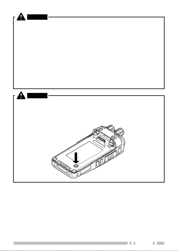
WARNING
●
Do not remove the black sheet from the reverse side of the
transceiver (refer to the illustration below). Removal of this sheet
decreases the waterproof efficiency of the transceiver and may
cause malfunctions if water seeps into the transceiver.
5

CAUTION
●
Do not disassemble or modify the transceiver for any reason.
●
Do not place the transceiver on or near airbag equipment while the
vehicle is running. When the airbag inflates, the transceiver may be
ejected and strike the driver or passengers.
●
Do not transmit while touching the antenna terminal or if any metallic
parts are exposed from the antenna covering. Transmitting at such
a time may result in a high-frequency burn.
●
If an abnormal odor or smoke is detected coming from the
transceiver, switch the transceiver power off immediately, remove
the battery pack from the transceiver, and contact your KENWOOD
dealer.
●
Use of the transceiver while you are driving may be against traffic
laws. Please check and observe the vehicle regulations in your
area.
●
Do not expose the transceiver to extremely hot or cold conditions.
●
Do not carry the battery pack (or battery case) with metal objects,
as they may short the battery terminals.
●
Danger of explosion if the battery is incorrectly replaced; replace
only with the same type.
●
When attaching a commercial strap to the transceiver, ensure that
the strap is durable. In addition, do not swing the transceiver around
by the strap; you may inadvertently strike and injure another person
with the transceiver.
●
If a commercially available neck strap is used, take care not to let
the strap get caught on nearby machine.
●
When operating the transceiver in areas where the air is dry, it is
easy to build up an electric charge (static electricity). When using
an earphone accessory in such conditions, it is possible for the
transceiver to send an electric shock through the earphone and to
your ear. We recommend you use only a speaker/microphone in
these conditions, to avoid electric shocks.
●
Do not expose the transceiver to long periods of direct sunlight, nor
place it near heating appliances.
6

Information concerning the battery pack:
The battery pack includes flammable objects such as organic solvent.
Mishandling may cause the battery to rupture producing flames or
extreme heat, deteriorate, or cause other forms of damage to the battery.
Please observe the following prohibitive matters.
DANGER
●
Do not disassemble or reconstruct the battery!
The battery pack has a safety function and protection circuit to avoid
danger. If they suffer serious damage, the battery may generate
heat or smoke, rupture, or burst into flame.
●
Do not short-circuit the battery!
Do not join the + and – terminals using any form of metal (such as
a paper clip or wire). Do not carry or store the battery pack in
containers holding metal objects (such as wires, chain-necklaces
or hairpins). If the battery pack is short-circuited, excessive current
will flow and the battery may generate heat or smoke, rupture, or
burst into flame. It will also cause metal objects to heat up.
●
Do not incinerate or apply heat to the battery!
If the insulator is melted, the gas release vent or safety function is
damaged, or the electrolyte is ignited, the battery may generate
heat or smoke, rupture, or burst into flame.
●
Do not leave the battery near fires, stoves, or other heat
generators (areas reaching over 80°C/ 176°F)!
If the polymer separator is melted due to high temperature, an
internal short-circuit may occur in the individual cells and the battery
may generate heat or smoke, rupture, or burst into flame.
●
Avoid immersing the battery in water or getting it wet by other
means!
If the battery becomes wet, wipe it off with a dry towel before use.
If the battery’s protection circuit is damaged, the battery may charge
at extreme current (or voltage) and an abnormal chemical reaction
may occur. The battery may generate heat or smoke, rupture, or
burst into flame.
7

DANGER
●
Do not charge the battery near fire or under direct sunlight!
If the battery’s protection circuit is damaged, the battery may charge
at extreme current (or voltage) and an abnormal chemical reaction
may occur. The battery may generate heat or smoke, rupture, or
burst into flame.
●
Use only the specified charger and observe charging
requirements!
If the battery is charged in unspecified conditions (under high
temperature over the regulated value, excessive high voltage or
current over regulated value, or with a remodeled charger), it may
overcharge or an abnormal chemical reaction may occur. The
battery may generate heat or smoke, rupture, or burst into flame.
●
Do not pierce the battery with any object, strike it with an
instrument, or step on it!
This may break or deform the battery, causing a short-circuit. The
battery may generate heat or smoke, rupture, or burst into flame.
●
Do not jar or throw the battery!
An impact may cause the battery to leak, generate heat or smoke,
rupture, and/or burst into flame. If the battery’s protection circuit is
damaged, the battery may charge at an abnormal current (or
voltage), and an abnormal chemical reaction may occur.
●
Do not use the battery pack if it is damaged in any way!
The battery may generate heat or smoke, rupture, or burst into
flame.
●
Do not solder directly onto the battery!
If the insulator is melted or the gas release vent or safety function
is damaged, the battery may generate heat or smoke, rupture, or
burst into flame.
●
Do not reverse the battery polarity (and terminals)!
When charging a reversed battery, an abnormal chemical reaction
may occur. In some cases, an unexpected large amount of current
may flow upon discharging. The battery may generate heat or
smoke, rupture, or burst into flame.
8

DANGER
●
Do not reverse-charge or reverse-connect the battery!
The battery pack has positive and negative poles. If the battery pack
does not smoothly connect with a charger or operating equipment,
do not force it; check the polarity of the battery. If the battery pack
is reverse-connected to the charger, it will be reverse-charged and
an abnormal chemical reaction may occur. The battery may
generate heat or smoke, rupture, or burst into flame.
●
Do not touch a ruptured and leaking battery!
If the electrolyte liquid from the battery gets into your eyes, wash
your eyes with fresh water as soon as possible, without rubbing your
eyes. Go to the hospital immediately. If left untreated, it may cause
eye-problems.
WARNING
●
Do not charge the battery for longer than the specified time!
If the battery pack has not finished charging even after the regulated
time has passed, stop it. The battery may generate heat or smoke,
rupture, or burst into flame.
●
Do not place the battery pack into a microwave or high
pressure container!
The battery may generate heat or smoke, rupture, or burst into
flame.
●
Keep ruptured and leaking battery packs away from fire!
If the battery pack is leaking (or the battery emits a bad odor),
immediately remove it from flammable areas. Electrolyte leaking
from battery can easily catch on fire and may cause the battery to
generate smoke or burst into flame.
●
Do not use an abnormal battery!
If the battery pack emits a bad odor, appears to have color changes,
is deformed, or seems abnormal for any other reason, remove it
from the charger or operating equipment and do not use it. The
battery may generate heat or smoke, rupture, or burst into flame.
9

NOTIFICATION OF WATER-RESISTANT MODEL
Water Resistance and Maintenance
Water-Resistant Model transceiver conforms to the following standards.
IP67: The IP standard is the protection level specified by the international
standard IEC 60529. The first numeral indicates the “dust-resistant level”
and the second numeral indicates the “water-resistant” level.
Note:
●
Initial water-resistant tests and procedures are performed products
upon being ordered from KENWOOD.
PRECAUTIONS
●
The applicable standards listed above do not assure that the
transceiver can be used in water. The transceiver may be damaged in
a situation in which the maximum depth is over 1 meter or the maximum
submersion time exceeds 30 minutes.
●
Observe the following precautions to maintain the transceiver’s water-
resistant performance:
a) Do not drop or apply strong physical shocks to the transceiver.
b) Do not disassemble or attempt to modify the transceiver. (If it is
disassembled or modified, its performance is not guaranteed.)
c) Do not soak the transceiver in water that contains a solvent or
surfactant, such as detergent or alcohol.
●
If it is soaked in muddy water or salt water (including sea water), it may
become corroded. Immediately flush with fresh water and then wipe
dry with a soft cloth.
●
If water is splashed onto the microphone, the battery, or the antenna
terminal, clean and dry them with a soft cloth before reconnecting to
the transceiver.
●
When water gets into the microphone opening or the speaker grill, the
voice level may become low or distorted. Lightly shake the transceiver
to remove the water from the speaker and/or microphone before
operating the transceiver.
●
Use of any option on the transceiver not specified by KENWOOD, may
reduce or void the water resistant and dust resistant performance.
10

UNPACKING AND CHECKING EQUIPMENT
Note:
●
The following unpacking instructions are for use by your KENWOOD
dealer, an authorized KENWOOD service facility, or the factory.
Carefully unpack the transceiver. We recommend that you
identify the items listed below before discarding the packing
material. If any items are missing or have been damaged during
shipment, file a claim with the carrier immediately.
SUPPLIED ACCESSORIES
Belt clip ................................................................................................. 1
●
Screws for belt clip (M3 x 8 mm) ..................................................... 2
Universal connector cap <NX-3200/ NX-3300 only> ............................ 1
Speaker/ microphone jacks cap <NX-3220/ NX-3320 only> ................ 1
Speaker/ microphone locking bracket <NX-3220/ NX-3320 only> ........ 1
Stopper <Full Button Model and Standard Button Model only> ............ 1
User Guide ........................................................................................... 1
11
PREPARATION
Release latch
2
1
3
Release latch
Safety catch
INSTALLING/ REMOVING THE (OPTIONAL) BATTERY PACK
CAUTION
●
Do not short the battery terminals or dispose of the battery by fire.
●
Never attempt to remove the casing from the battery pack.
●
Install the battery pack after cleaning the battery pack contacts and
the transceiver terminals.
●
Before charging a battery pack that is attached to the transceiver,
ensure that the safety catch is firmly closed.
.
●
If the release latch is tilted and the battery
pack is not attached to the transceiver,
return the release latch to its original
position using your finger.
1
Match the guides of the battery pack with the corresponding
grooves on the upper rear of the transceiver, then firmly press
the battery pack to lock it in place.
2
Lock the safety catch to prevent accidentally pressing the
release latch and removing the battery pack.
3
To remove the battery pack, lift the safety catch, press the
release latch, then pull the battery pack away from the
transceiver.
12
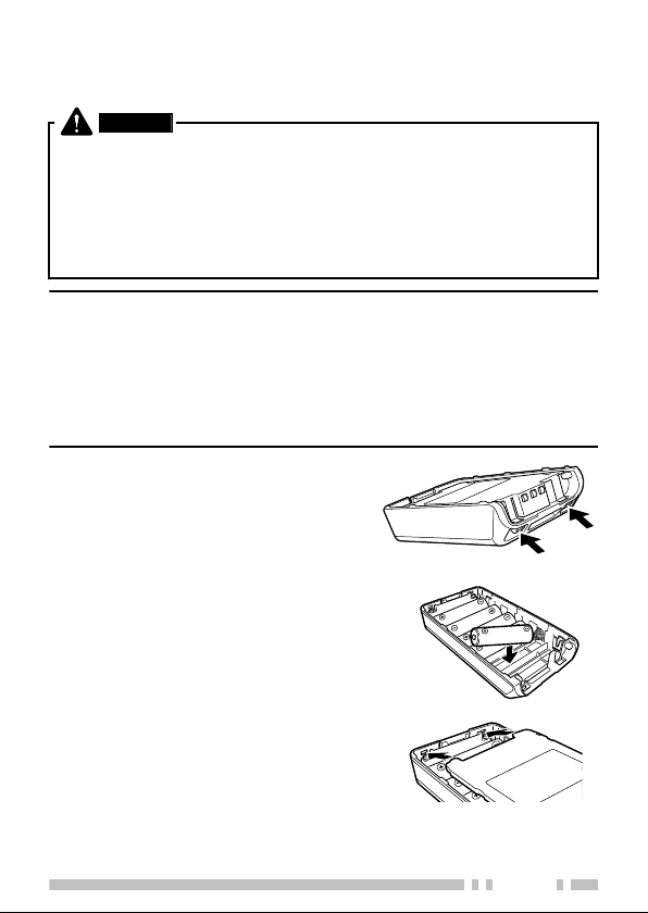
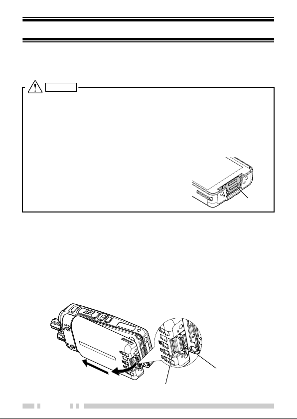
INSTALLING/ REMOVING ALKALINE BATTERIES (OPTIONAL BATTERY CASE)
WARNING
●
Do not install batteries in a hazardous environment where sparks
could cause an explosion.
●
Never discard batteries in fire; extremely high temperatures can
cause batteries to explode.
●
Do not short circuit the battery case terminals.
●
Do not use rechargeable batteries.
Note:
●
If you do not plan to use the transceiver for a long period, remove the
batteries from the battery case.
●
This battery case has been designed for transmitting at a power of
approximately 1 W (the low power setting on your transceiver). If you
want to transmit a stronger signal (using the high power setting on
your transceiver), use an optional rechargeable battery pack.
.
1
To open the battery case, press
on the two tabs on the upper rear
of the case, then pull the two
halves apart.
.
2
Insert 6 AA (LR6) Alkaline batteries
into the battery case.
●
Be sure to match the polarities with
those marked in the bottom of the
battery case.
.
3
Align the tabs of the cover with
the base, then push down on the
cover until it locks in place.
13
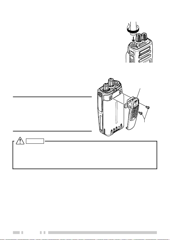
INSTALLING THE (OPTIONAL) ANTENNA
Optional
antenna
Belt clip
M3 x 8 mm
screws
.
Screw the antenna into the connector on the top
of the transceiver by holding the antenna at its
base and turning it clockwise until secure.
.
INSTALLING THE BELT CLIP
.
If necessary, attach the belt clip
using the two supplied M3 x 8 mm
binding screws.
Note:
●
If the belt clip is not installed, its
mounting location may get hot
during continuous transmission or
when left sitting in a hot
environment.
CAUTION
Do not use glue which is designed to prevent screw loosening when
installing the belt clip, as it may cause damage to the transceiver.
Acrylic ester, which is contained in these glues, may crack the
transceiver’s back panel.
14
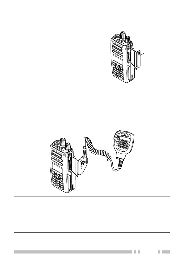
INSTALLING THE CAP OVER THE UNIVERSAL
Optional speaker/
microphone
Universal
connector cap
CONNECTOR <NX-3200/ NX-3300>
.
1
If you are not using an optional
speaker/ microphone or headset,
install the cap over the universal
connector.
2
Secure the cap in place using the
dressing screw.
.
INSTALLING THE (OPTIONAL) SPEAKER/ MICROPHONE OR HEADSET <NX-3200/ NX-3300>
1
Insert the guide of the speaker/ microphone or headset
connector into the groove of the universal connector.
2
Secure the connector in place using the attached screw.
Note:
●
When not using an optional speaker/ microphone or headset, install
the cap over the universal connector.
●
The noise canceling function on KMC-54WD Speaker Microphone
works using the built-in DSP of the transceiver, and can be used only
with the NX-3000 series Portable models.
15
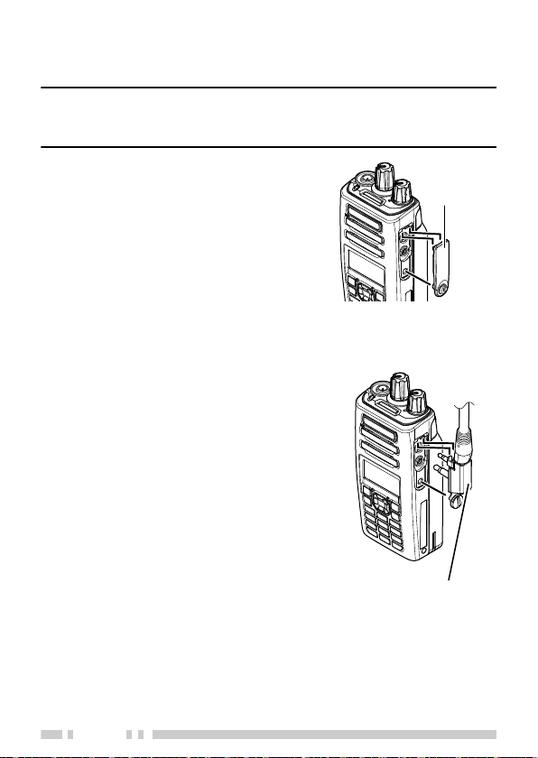
INSTALLING THE CAP OVER THE SPEAKER/
Speaker/
microphone
jacks cap
Speaker/ microphone
locking bracket
MICROPHONE JACKS <NX-3220/ NX-3320>
Note:
●
To keep the transceiver water resistant, you must cover the speaker/
microphone jacks with the supplied cap.
.
1
If you are not using an optional
speaker/ microphone or headset,
install the cap over the speaker/
microphone jacks.
2
Secure the cap in place using the
dressing screw.
.
INSTALLING THE (OPTIONAL) SPEAKER/ MICROPHONE OR HEADSET <NX-3220/ NX-3320>
.
1
Insert the speaker/ microphone plugs
into the speaker/ microphone jacks of
the transceiver.
2
Place the locking bracket over the
speaker/ microphone plugs so that
the locking tabs insert into the
transceiver grooves.
3
Secure the locking bracket in place
using the dressing screw.
16
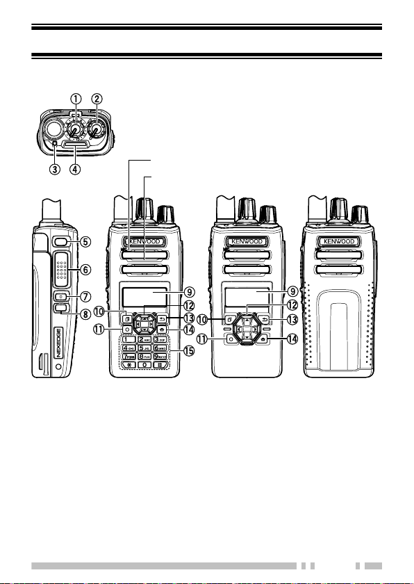
ORIENTATION
Speaker
Microphone
Full button model Standard button model Basic button model
BUTTONS AND CONTROLS
A
Selector
Rotate this control to activate its programmable function. The default
setting is [Channel Select].
B
Power switch/ Volume control
Turn clockwise to switch the transceiver ON. To switch the transceiver
OFF, turn counterclockwise fully. Rotate to adjust the volume level.
17

C
Transmit/ Receive/ Battery low indicator
The indicator lights in different colors to indicate the current status of
the transceiver.
Lights red while transmitting and green while receiving.
Flashes red when the battery power is low while transmitting. Replace
or recharge the battery pack when the battery power is low.
Note:
●
This indicator can be disabled by your dealer.
D
Light bar
Lights up when selecting or receiving a channel.
Note:
●
This indicator can be disabled by your dealer.
E
Auxiliary (orange) button
Press to activate its programmable function.
F
PTT (Push To Talk) switch
Press and hold, then speak into the microphone to call a station.
G
Side 1 button
Press to activate its programmable function. The default button setting
is [Squelch Off Momentary].
H
Side 2 button
Press to activate its programmable function. The default button setting
is [Backlight].
I
LCD display
Refer to the display. {p. 20}
J
[
] button
Press to activate its programmable function. The default button setting
is [Menu].
K
] button
[
Press to activate its programmable function. The default button setting
is [Function].
18

L
4-way D-pad (Full Button Model/ Standard Button Model)
Press to activate its programmable function.
[H] : The default setting is [None].
[I] : The default setting is [None].
[J] : The default setting is [Zone Up].
[K] : The default setting is [Zone Down].
M
] button
[
Press to activate its programmable function. The default button setting
is [None].
N
[ ] button
Press to activate its programmable function. The default button setting
is [Clear].
O
Keypad (Full button model only)
Press the buttons on the keypad to send DTMF tones. The keypad
buttons can also be programmed with secondary functions if a
programmable function button is programmed as Function.
.
For details on programming functions to the buttons on your
transceiver, please contact your dealer or refer to the “User
Manual” available from the following URL.
http://manual.kenwood.com/en_contents/search/keyword
.
19
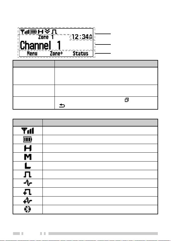
DISPLAY
Function Indicator Area
Main Area
Button Guide Area
Basic Frame
Display Area Description
Function Indicator
Area
Main Area
Button Guide Area
Function Indicator
Indicator Description
Displays the various function indicators, signal
strength indicator, battery power indicator and
clock.
Displays the information of the transceiver such
as Channel number and Zone number.
Displays the button functions for [ ], [J] and
[ ].
Displays the signal strength.
Displays the battery power.
The channel is using high transmit power.
The channel is using medium transmit power.
The channel is using low transmit power.
In Digital mode (Digital Channel)
In Analog mode (Analog Channel)
In Digital mode (Mixed Channel)
In Analog mode (Mixed Channel)
Connected to a Bluetooth device.
20
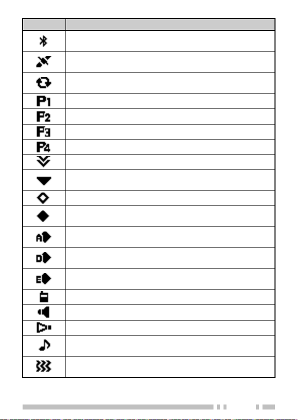
Indicator Description
The Bluetooth function is activated. Blinks in the process
of turning on Bluetooth.
The GPS position is determined. Blinks when the GPS is
unable to determine the position.
Scan, Priority Scan or Voting/ Site Roaming is in progress.
Blinks when the scan is paused.
Indicates Priority channel 1 or Priority Monitor ID 1.
Indicates Priority channel 2 or Priority Monitor ID 2.
Indicates Priority Monitor ID 3.
Indicates Priority Monitor ID 4.
The current channel is added to the scanning sequence.
The current zone is added to the Multi-Zone scanning
sequence.
The Scrambler function is activated.
The Encryption function is activated. Blinks when receiving
an encrypted carrier.
The Encryption (AES) function is activated. Blinks when
receiving an encrypted carrier.
The Encryption (DES) function is activated. Blinks when
receiving an encrypted carrier.
The Encryption (ARC4) function is activated. Blinks when
receiving an encrypted carrier.
The Talk Around function is activated.
The Monitor or Squelch Off function is activated.
The External Speaker is activated.
Blinks when an incoming call matches your Optional
Signaling.
The Vibrator function is activated. Blinks when the Vibrator
is not functioning.
21
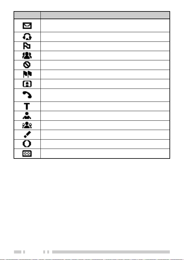
Indicator Description
A message is stored in the memory. Blinks when a new
message is received.
The VOX function is activated.
The Site Lock function is activated.
The Broadcast Call function is activated.
The Surveillance function is activated.
The System Lock function is activated.
The auxiliary port is activated.
Appears when the selected group is programmed as
telephone IDs.
The Tactical Zone is activated.
The Lone Worker function is activated.
The OVCM function is activated.
The Activity Detection function is activated.
The Operator Selectable Tone function is activated.
Blinks during Auto Recording.
22

BASIC OPERATIONS
SWITCHING POWER ON/ OFF
Turn the Power switch/ Volume control clockwise to switch the
transceiver power ON.
Turn the Power switch/ Volume control counterclockwise to
switch the transceiver power OFF.
ADJUSTING THE VOLUME
Rotate the Power switch/ Volume control to adjust the volume.
SELECTING A ZONE AND CHANNEL
1
Select the desired zone using the Selector, 4-way D-pad or
the buttons programmed as [Zone Up]/ [Zone Down]. Each
zone contains a group of channels.
2
Select the desired channel using the Selector, 4-way Dpad or the buttons programmed as [Channel Up]/ [Channel
Down]. Each channel is programmed with settings for
transmitting and receiving.
●
The default setting for the Selector is [Channel Select].
●
The transceiver may have names programmed for zones and
channels. The zone name and channel name can contain up to 12
and 14 characters respectively. While selecting a zone, the zone
name will appear above the channel name.
●
If programmed by your dealer, your transceiver will announce the
zone and channel numbers as you change them.
23

TRANSMITTING
1
Select the desired zone and channel using the Selector or 4-
way D-pad and the [Zone Up]/ [Zone Down] or [Channel
Up]/ [Channel Down] buttons.
2
Press the PTT switch and speak into the microphone. Release
the PTT switch to receive.
●
The LED indicator lights red while transmitting and green while
receiving a signal. This indicator can also be disabled by your
dealer.
●
For best sound quality at the receiving station, hold the
microphone approximately 3 cm to 4 cm (1.5 inches) from your
mouth.
RECEIVING
Select the desired zone and channel. If signaling has been
programmed on the selected channel, you will hear a call only if
the received signal matches your transceiver settings.
24

INFORMATION ON SOFTWARE LICENSE
This transceiver uses a software according to the following license
agreements.
*zlib LICENSE
Copyright (C) 1995-2013 Jean-loup Gailly and Mark Adler
This software is provided 'as-is', without any express or implied warranty.
In no event will the authors be held liable for any damages arising from the
use of this software.
Permission is granted to anyone to use this software for any purpose,
including commercial applications, and to alter it and redistribute it freely,
subject to the following restrictions:
1. The origin of this software must not be misrepresented; you must not
claim that you wrote the original software. If you use this software in
a product, an acknowledgment in the product documentation would
be appreciated but is not required.
2. Altered source versions must be plainly marked as such, and must
not be misrepresented as being the original software.
3. This notice may not be removed or altered from any source
distribution.
Jean-loup Gailly (jloup@gzip.org)
Mark Adler (madler@alumni.caltech.edu)
*libpng LICENSE
This copy of the libpng notices is provided for your convenience. In case of
any discrepancy between this copy and the notices in the file png.h that is
included in the libpng distribution, the latter shall prevail.
COPYRIGHT NOTICE, DISCLAIMER, and LICENSE:
If you modify libpng you may insert additional notices immediately following
this sentence.
This code is released under the libpng license.
libpng versions 1.2.6, August 15, 2004, through 1.6.8, December 19, 2013,
are Copyright (c) 2004, 2006-2013 Glenn Randers-Pehrson, and are
distributed according to the same disclaimer and license as libpng-1.2.5
with the following individual added to the list of Contributing Authors
Cosmin Truta
libpng versions 1.0.7, July 1, 2000, through 1.2.5 - October 3, 2002, are
Copyright (c) 2000-2002 Glenn Randers-Pehrson, and are distributed
according to the same disclaimer and license as libpng-1.0.6 with the
following individuals added to the list of Contributing Authors
25

Simon-Pierre Cadieux
Eric S. Raymond
Gilles Vollant
and with the following additions to the disclaimer:
There is no warranty against interference with your enjoyment of the
library or against infringement. There is no warranty that our efforts or
the library will fulfill any of your particular purposes or needs. This library
is provided with all faults, and the entire risk of satisfactory quality,
performance, accuracy, and effort is with the user.
libpng versions 0.97, January 1998, through 1.0.6, March 20, 2000, are
Copyright (c) 1998, 1999 Glenn Randers-Pehrson, and are distributed
according to the same disclaimer and license as libpng-0.96, with the
following individuals added to the list of Contributing Authors:
Tom Lane
Glenn Randers-Pehrson
Willem van Schaik
libpng versions 0.89, June 1996, through 0.96, May 1997, are Copyright (c)
1996, 1997 Andreas Dilger
Distributed according to the same disclaimer and license as libpng-0.88,
with the following individuals added to the list of Contributing Authors:
John Bowler
Kevin Bracey
Sam Bushell
Magnus Holmgren
Greg Roelofs
Tom Tanner
libpng versions 0.5, May 1995, through 0.88, January 1996, are Copyright
(c) 1995, 1996 Guy Eric Schalnat, Group 42, Inc.
For the purposes of this copyright and license, “Contributing Authors” is
defined as the following set of individuals:
Andreas Dilger
Dave Martindale
Guy Eric Schalnat
Paul Schmidt
Tim Wegner
The PNG Reference Library is supplied “AS IS”. The Contributing Authors
and Group 42, Inc. disclaim all warranties, expressed or implied, including,
without limitation, the warranties of merchantability and of fitness for any
purpose. The Contributing Authors and Group 42, Inc. assume no liability
for direct, indirect, incidental, special, exemplary, or consequential
damages, which may result from the use of the PNG Reference Library,
even if advised of the possibility of such damage.
26

Permission is hereby granted to use, copy, modify, and distribute this
source code, or portions hereof, for any purpose, without fee, subject to the
following restrictions:
1. The origin of this source code must not be misrepresented.
2. Altered versions must be plainly marked as such and must not be
misrepresented as being the original source.
3. This Copyright notice may not be removed or altered from any source
or altered source distribution.
The Contributing Authors and Group 42, Inc. specifically permit, without fee,
and encourage the use of this source code as a component to supporting
the PNG file format in commercial products. If you use this source code in
a product, acknowledgment is not required but would be appreciated.
A “png_get_copyright” function is available, for convenient use in “about”
boxes and the like:
printf("%s",png_get_copyright(NULL));
Also, the PNG logo (in PNG format, of course) is supplied in the files
“pngbar.png” and “pngbar.jpg” (88x31) and “pngnow.png” (98x31).
Libpng is OSI Certified Open Source Software. OSI Certified Open Source
is a certification mark of the Open Source Initiative.
Glenn Randers-Pehrson
glennrp at users.sourceforge.net
December 19, 2013
*Md5
Copyright (C) 1999, 2000, 2002 Aladdin Enterprises. All rights reserved.
This software is provided 'as-is', without any express or implied warranty.
In no event will the authors be held liable for any damages arising from the
use of this software.
Permission is granted to anyone to use this software for any purpose,
including commercial applications, and to alter it and redistribute it freely,
subject to the following restrictions:
1. The origin of this software must not be misrepresented; you must not
claim that you wrote the original software. If you use this software in
a product, an acknowledgment in the product documentation would
be appreciated but is not required.
2. Altered source versions must be plainly marked as such, and must
not be misrepresented as being the original software.
3. This notice may not be removed or altered from any source
distribution.
L. Peter Deutsch
ghost@aladdin.com
27

 Loading...