

Kenwood NX-3000 Series, NX-3820H, NX-3820HG, NX-3720H, NX-3720HG User Manual

.
NX-3000 series
USER GUIDE
GUIDE DE L’UTILISATEUR
GUÍA DEL USUARIO
.
.
.
B5A-1562-00 (K)


VHF DIGITAL TRANSCEIVER
NX-3720H
NX-3720HG
UHF DIGITAL TRANSCEIVER
NX-3820H
NX-3820HG
USER GUIDE
.
This User Guide covers only the basic operations of your radio. Ask your dealer for
information on any customized features they may have added to your radio. For using
details User Manual, refer to the following URL.
http://manual.kenwood.com/en_contents/search/keyword
.
●
The Bluetooth® word mark and logo are registered trademarks owned by Bluetooth SIG, Inc.
and any use of such marks by JVC KENWOOD Corporation is under license. Other
trademarks and trade names are those of their respective owners.

THANK YOU
We are grateful you have chosen KENWOOD for your Digital Transceiver
applications.
CONTENTS
NOTICES TO THE USER ............................................................................................................ 3
PRECAUTIONS ........................................................................................................................... 4
TERMINAL DESCRIPTIONS ...................................................................................................... 5
UNPACKING AND CHECKING EQUIPMENT ............................................................................ 6
SUPPLIED ACCESSORIES ...................................................................................................... 6
PREPARATION ........................................................................................................................... 7
ORIENTATION ............................................................................................................................ 9
OPERATION PANEL ................................................................................................................. 9
DISPLAY ................................................................................................................................. 10
BASIC OPERATIONS ............................................................................................................... 13
SWITCHING POWER ON/ OFF .............................................................................................. 13
ADJUSTING THE VOLUME .................................................................................................... 13
SELECTING A ZONE AND CHANNEL ................................................................................... 13
TRANSMITTING ..................................................................................................................... 13
RECEIVING ............................................................................................................................. 13
INFORMATION ON SOFTWARE LICENSE ............................................................................. 14
MANDATORY SAFETY INSTRUCTIONS TO INSTALLERS AND USERS
(For VHF DIGITAL TRANSCEIVER) ........................................................................................ 16
MANDATORY SAFETY INSTRUCTIONS TO INSTALLERS AND USERS
(For UHF DIGITAL TRANSCEIVER) ........................................................................................ 16
2

NOTICES TO THE USER
●
Government law prohibits the operation of unlicensed radio transmitters within the territories under
government control.
●
Illegal operation is punishable by fine and/or imprisonment.
●
Refer service to qualified technicians only.
Safety: It is important that the operator is aware of, and understands, hazards
common to the operation of any transceiver.
WARNING
●
EXPLOSIVE ATMOSPHERES (GASES, DUST, FUMES, etc.)
Turn OFF your transceiver while taking on fuel or while parked in gasoline service stations. Do not
carry spare fuel containers in the trunk of your vehicle if your transceiver is mounted in the trunk
area.
●
INJURY FROM RADIO FREQUENCY TRANSMISSIONS
Do not operate your transceiver when somebody is either standing near to or touching the antenna,
to avoid the possibility of radio frequency burns or related physical injury.
●
DYNAMITE BLASTING CAPS
Operating the transceiver within 500 feet (150 m) of dynamite blasting caps may cause them to
explode. Turn OFF your transceiver when in an area where blasting is in progress, or where “TURN
OFF TWO-WAY RADIO” signs have been posted. If you are transporting blasting caps in your
vehicle, make sure they are carried in a closed metal box with a padded interior. Do not transmit
while the caps are being placed into or removed from the container.
One or more of the following statements may be applicable:
FCC WARNING
This equipment generates or uses radio frequency energy. Changes or modifications to this equipment
may cause harmful interference unless the modifications are expressly approved by the party
responsible/ JVC KENWOOD. The user could lose the authority to operate this equipment if an
unauthorized change or modification is made.
INFORMATION TO THE DIGITAL DEVICE USER REQUIRED BY THE FCC
This equipment has been tested and found to comply with the limits for a Class B digital device, pursuant
to Part 15 of the FCC Rules. These limits are designed to provide reasonable protection against harmful
interference in a residential installation.
This equipment generates, uses and can generate radio frequency energy and, if not installed and used
in accordance with the instructions, may cause harmful interference to radio communications. However,
there is no guarantee that the interference will not occur in a particular installation. If this equipment
does cause harmful interference to radio or television reception, which can be determined by turning
the equipment off and on, the user is encouraged to try to correct the interference by one or more of the
following measures:
●
Reorient or relocate the receiving antenna.
●
Increase the separation between the equipment and receiver.
●
Connect the equipment to an outlet on a circuit different from that to which the receiver is connected.
●
Consult the dealer for technical assistance.
This device complies with Industry Canada licence-exempt RSS standard(s). Operation is subject to the
following two conditions: (1) this device may not cause interference, and (2) this device must accept any
interference, including interference that may cause undesired operation of the device.
3
The AMBE+2™ voice coding Technology embodied in this product is protected by intellectual property rights
including patent rights, copyrights and trade secrets of Digital Voice Systems, Inc. This voice coding
Technology is licensed solely for use within this Communications Equipment. The user of this Technology is
explicitly prohibited from attempting to extract, remove, decompile, reverse engineer, or disassemble the
Object Code, or in any other way convert the Object Code into a human-readable form. U.S. Patent Nos.
#8,315,860, #8,595,002, #6,199,037, #6,912,495, #8,200,497, #7,970,606 and #8,359,197
Firmware Copyrights
The title to and ownership of copyrights for firmware embedded in KENWOOD product memories are
reserved for JVC KENWOOD Corporation.
PRECAUTIONS
Observe the following precautions to prevent fire, personal injury, and transceiver
damage.
●
Do not attempt to configure the transceiver while driving; it is too dangerous.
●
Do not disassemble or modify the transceiver for any reason.
●
Do not expose the transceiver to long periods of direct sunlight, nor place it near heating appliances.
●
If an abnormal odor or smoke is detected coming from the transceiver, switch the transceiver power
off immediately, and contact your KENWOOD dealer.
●
Use of the transceiver while you are driving may be against traffic laws. Please check and observe the
vehicle regulations in your area.
●
Do not use options not specified by KENWOOD.
●
Do not put the plastic bag used for packing of this equipment on the place which reaches a small child's
hand. It will become a cause of suffocation if it wears flatly.
●
Do not place the transceiver on unstable surfaces.
●
Keep the volume as low as possible to protect your hearing.
●
Always switch the transceiver power off before installing optional accessories.
●
To dispose of batteries, be sure to comply with the laws and regulations in your country or region.
CAUTION
●
The transceiver operates in 12 V negative ground systems only! Check the battery polarity and
voltage of the vehicle before installing the transceiver.
●
Use only the supplied DC power cable or a KENWOOD optional DC power cable.
●
Do not cut and/or remove the fuse holder on the DC power cable.
●
Do not place the microphone cable around your neck while near machinery that may catch the
cable.
WARNING
●
For passenger safety, install the transceiver securely using the supplied or optional mounting
bracket and screw set so the transceiver will not break loose in the event of a collision.
When using the transceiver, refer to the “NOTICES TO THE USER” and “PRECAUTIONS”. If the
warnings are not observed, there may be possibility of malfunction. In this case, press and hold the Power
Switch for 5 seconds or more. If the malfunction persists, ask your dealer.
4

TERMINAL DESCRIPTIONS
ACC (D-SUB 15 Pin Connector)
Pin No. Name I/O Description Specification
1 SB O DC Power (Switched B) Output Max. 2 A
2 IGN I Ignition Signal Input
3 SP2/ PA O Loudspeaker Output/ Public Address Output 4 Ω
4 DETO O RX Detected Audio Output 240 mVp-p (typ.)
5 DATAI I TX Data Input 45 kΩ
6 FNC1/ TXD I/O Programmable/ PC Serial Data from Radio High Impedance
7 FNC2/ RXD I/O Programmable/ PC Serial Data to Radio High Impedance
8 FNC3 I/O Programmable High Impedance
9 FNC4 I/O Programmable High Impedance
10 FNC5 I/O Programmable High Impedance
11 FNC6 I/O Programmable High Impedance
12 50AC O DC Power Output 5 V, Max. 100 mA
13 HR1 I Horn Alert Signal Input
14 HR2 O Horn Alert Signal Output Max 2 A
15 GND — Ground Ground
Speaker Jack (3.5 mm Phone Jack) 4 W/ 4 K
Pin No. Name I/O Description Specification
1 SPO O External Speaker Output 4 Ω (Min)
3 GND — Ground Ground
DC Input Connector
Pin No. Name I/O Description Specification
Red B I DC Power Input 13.6 V ±15%
Black GND — Ground Ground
Microphone Jack
Pin No. Name I/O Description Specification
1 BLC/ D+ O MIC Backlight Control/ USB Data+
2 SB O DC Power (Switched B) Output Max 200 mA
3 GND — Ground Ground
4 PTT/ TXD I/O PTT/ PC Serial Data from Radio High Impedance
5 ME — Mic Ground Ground
6 MIC/ VBUS I Mic Signal Input/ USB VBUS 680 Ω
HOOK/ RXD/
7
D-
8 DM I/O Mic Data Detection
I Hook/ PC Serial Data to Radio/ USB Data- High Impedance
RF Antenna Terminal
50 K impedance
GPS Antenna Terminal (NX-3720HG/ NX-3820HG only)
50 K impedance
Min. Input: 10.8 V
Max. Input: 16.0 V
Min. Input: 5 V
Max. Input: 16.0 V
5

UNPACKING AND CHECKING EQUIPMENT
Note:
●
The following unpacking instructions are for use by your KENWOOD dealer, an authorized
KENWOOD service facility, or the factory.
Carefully unpack the transceiver. We recommend that you identify the items listed
below before discarding the packing material. If any items are missing or have been
damaged during shipment, file a claim with the carrier immediately.
SUPPLIED ACCESSORIES
DC power cable (with fuses) ................................................................................................ 1
●
15 A fuse ......................................................................................................................... 2
Mounting bracket ................................................................................................................. 1
Screw set
●
5 x 16 mm self-tapping screw ......................................................................................... 4
●
M4 x 6 mm hex-headed screw with washer .................................................................... 4
●
Spring washer ................................................................................................................. 4
●
Flat washer ..................................................................................................................... 4
Microphone (with cable)
●
KMC-35 .......................................................................................................................... 1
Microphone hanger (with 4 x 16 mm self-tapping screws) ................................................... 1
User Guide ........................................................................................................................... 1
6
PREPARATION
WARNING
Various electronic equipment in your vehicle may malfunction if they are not properly protected from
the radio frequency energy which is present while transmitting. Typical examples include electronic
fuel injection, anti-skid braking, and cruise control. If your vehicle contains such equipment, consult
the dealer for the make of vehicle and enlist his/her aid in determining if they will perform normally
while transmitting.
o
Connecting the power cable
CAUTION
The transceiver operates in 12 V negative ground systems only! Check the battery polarity and voltage
of the vehicle before installing the transceiver.
1
Check for an existing hole, conveniently located in the firewall, where the power
cable can be passed through.
●
If no hole exists, use a circle cutter to drill a hole, then install a rubber grommet.
2
Run the power cable through the firewall and into the engine compartment.
3
Connect the red lead to the positive (+) battery terminal and the black lead to the
negative (–) battery terminal.
●
Place the fuse as close to the battery as possible.
4
Coil the surplus cable and secure it with a retaining band.
●
Be sure to leave enough slack in the cables so the transceiver can be removed for
servicing while keeping the power applied.
o
Installing the transceiver
WARNING
For passenger safety, install the transceiver securely using the supplied or optional mounting bracket
and screw set so the transceiver will not break loose in the event of a collision.
Note:
●
Before installing the transceiver, check how far the mounting screws will extend below the
surface. When drilling mounting holes, be careful not to damage vehicle wiring or parts.
1
Mark the position of the holes in the dash, using the mounting bracket as a
template. Using a 4.2 mm (5/32 inch) drill bit, drill the holes, then attach the
mounting bracket using the supplied screws.
●
Mount the transceiver within easy reach of the user and where there is sufficient space
at the rear of the transceiver for cable connections.
2
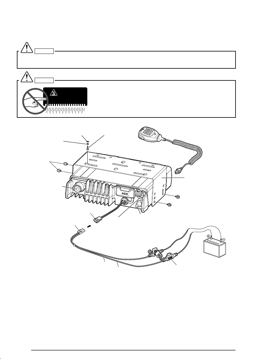
Connect the antenna and the supplied power cable to the transceiver.
3
Slide the transceiver into the mounting bracket and secure it using the supplied
hex-headed screws.
7
4
HOT SURFACE
5 x 16 mm
Self-tapping
screw
Flat washer
Spring washer
M4 x 6 mm
hex-headed
screw with
washer
RF antenna connector
External
speaker jack
Black (–) cable
Red (+) cable
Fuse
12 V vehicle battery
Mounting bracket
Microphone
Power input connector
DC power cable
GPS antenna connector for KRA-40
(NX-3720HG/ NX-3820HG only)
Mount the microphone hanger in a location where it will be within easy reach of
the user.
●
The microphone and microphone cable should be mounted in a place where they will
not interfere with the safe operation of the vehicle.
CAUTION
When replacing the fuse in the DC power cable, be sure to replace it with a fuse of the same rating.
Never replace a fuse with one that is rated with a higher capacity.
CAUTION
.
Do not touch the metal surface of the transceiver while it is in use.
Do not mount the transceiver such that the chassis can come in
contact with skin.
High temperatures may burn your skin.
8

ORIENTATION
AC
G
E
FD
B
OPERATION PANEL
A
[ ] (Power) switch
Press to switch the transceiver ON or OFF.
B
[+] / [-] buttons
Press to activate their programmable functions. The default button setting is
[Volume Up]/ [Volume Down].
C
[J]/ [K] buttons
Press to activate their programmable functions. The default button setting is
[Channel Up]/ [Channel Down].
D
TX/RX indicator
The indicator lights in different colors to indicate the current status of the
transceiver.
Lights red while transmitting and green while receiving.
E
Microphone jack
Insert the microphone plug into this jack.
F
[ ] / [ ] / [ ] / [H] / [I] / Auxiliary ( ) buttons
Press to activate their programmable functions.
] : The default button setting is [Clear].
[
[ ] : The default button setting is [Menu].
[ ] : The default button setting is [Squelch Off Momentary].
[H] : The default button setting is [Zone Down].
[I] : The default button setting is [Zone Up].
Auxiliary (
G
Speaker
Internal speaker.
.
For details on programming functions to the buttons on your transceiver, please contact your
dealer or refer to the “User Manual” available from the following URL.
http://manual.kenwood.com/en_contents/search/keyword
.
) : The default button setting is [None].
9
DISPLAY
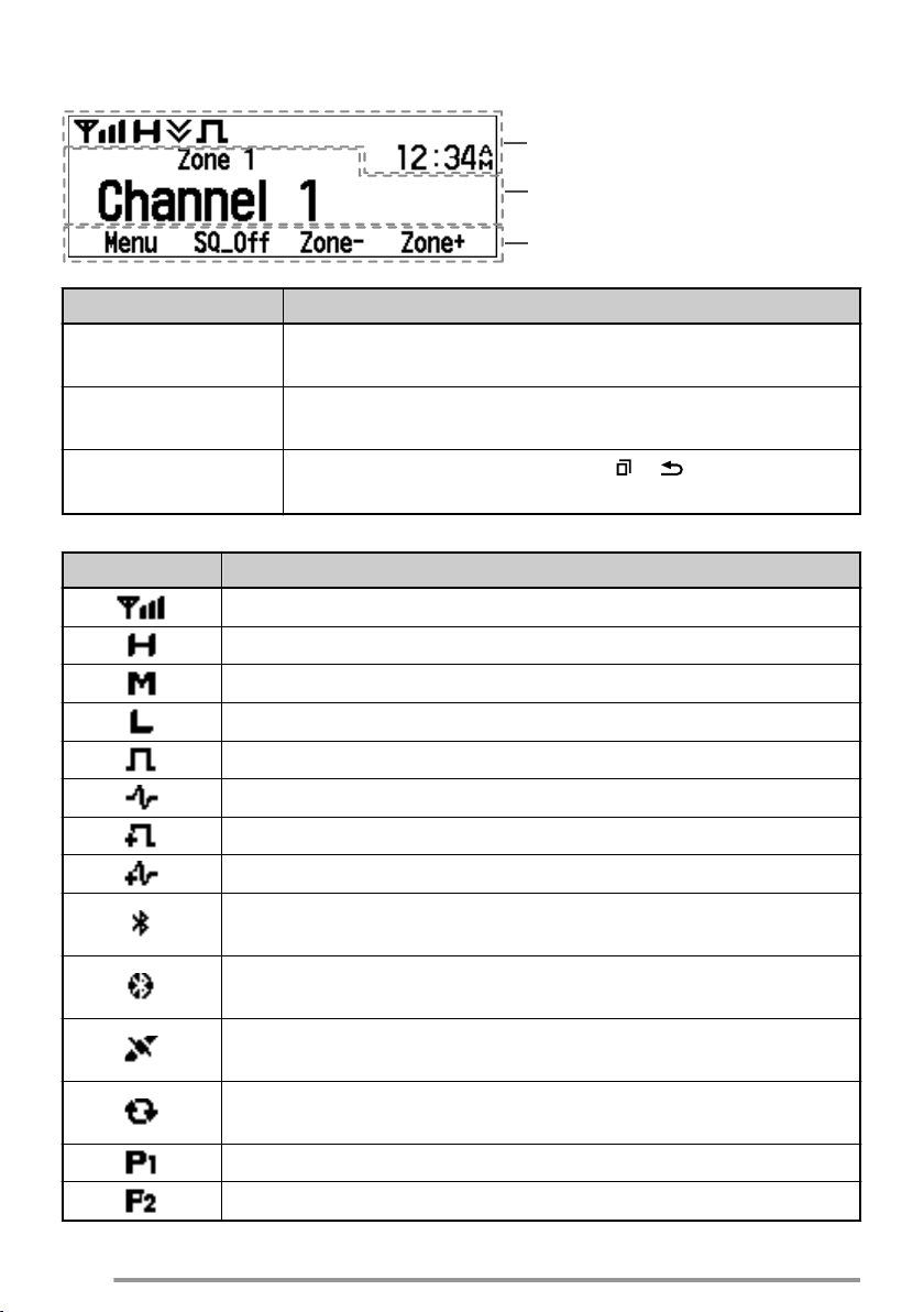
Main Area
Function Indicator Area
Button Guide Area
Basic Frame
Display Area Description
Function Indicator
Area
Main Area
Button Guide Area
Function Indicator
Indicator Description
Displays the various function indicators, signal strength
indicator and clock.
Displays the information of the transceiver such as Channel
number and Zone number.
Displays the button functions for [ ], [ ], [H] and [I]
buttons.
Displays the signal strength.
The channel is using high transmit power.
The channel is using medium transmit power.
10
The channel is using low transmit power.
In Digital mode (Digital Channel)
In Analog mode (Analog Channel)
In Digital mode (Mixed Channel)
In Analog mode (Mixed Channel)
The Bluetooth function is activated. Blinks in the process of turning
on Bluetooth. (NX-3720HG/ NX-3820HG only)
Connected to a Bluetooth device. (NX-3720HG/ NX-3820HG
only)
The GPS position is determined. Blinks when the GPS is unable
to determine the position. (NX-3720HG/ NX-3820HG only)
Scan, Priority Scan or Voting/ Site Roaming is in progress. Blinks
when the scan is paused.
Indicates Priority channel 1 or Priority Monitor ID 1.
Indicates Priority channel 2 or Priority Monitor ID 2.
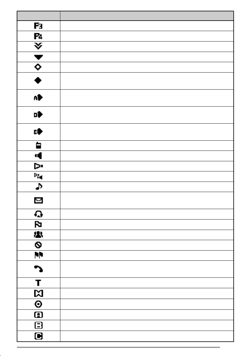
Indicator Description
Indicates Priority Monitor ID 3.
Indicates Priority Monitor ID 4.
The current channel is added to the scanning sequence.
The current zone is added to the Multi-Zone scanning sequence.
The Scrambler function is activated.
The Encryption function is activated. Blinks when receiving an
encrypted carrier.
The Encryption (AES) function is activated. Blinks when receiving
an encrypted carrier.
The Encryption (DES) function is activated. Blinks when receiving
an encrypted carrier.
The Encryption (ARC4) function is activated. Blinks when
receiving an encrypted carrier.
The Talk Around function is activated.
The Monitor or Squelch Off function is activated.
The External Speaker is activated.
The External Speaker (Internal + External) is activated.
Blinks when an incoming call matches your Optional Signaling.
A message is stored in the memory. Blinks when a new message
is received.
The VOX function is activated. (NX-3720HG/ NX-3820HG only)
The Site Lock function is activated.
The Broadcast Call function is activated.
The Surveillance function is activated.
The System Lock function is activated.
Appears when the selected group is programmed as telephone
IDs. Blinks during Auto Telephone search.
The Tactical Zone is activated.
The Horn Alert function is activated.
The Public Address function is activated.
AUX A is activated.
AUX B is activated.
AUX C is activated.
11

Indicator Description
The Lone Worker function is activated.
The OVCM function is activated.
The Operator Selectable Tone function is activated.
Blinks during Auto Recording.
12

BASIC OPERATIONS
SWITCHING POWER ON/ OFF
Press [ ] to switch the transceiver ON.
Press [
ADJUSTING THE VOLUME
Press the button programmed as [Volume Up] to increase the volume. Press the
button programmed as [Volume Down] to decrease the volume.
SELECTING A ZONE AND CHANNEL
Select the desired zone and channel using the buttons programmed as [Zone Up]/
[Zone Down] and [Channel Up]/ [Channel Down].
●
●
TRANSMITTING
1
2
RECEIVING
Select the desired zone and channel. If signaling has been programmed on the
selected channel, you will hear a call only if the received signal matches your
transceiver settings.
] again to switch the transceiver OFF.
The transceiver may have names programmed for zones and channels. The zone name
and channel name can contain up to 14 characters. While selecting a zone, the zone name
will appear above the channel name.
If programmed by your dealer, your transceiver will announce the zone and channel
numbers as you change them.
Select the desired zone and channel.
Press the PTT switch and speak into the microphone. Release the PTT switch to
receive.
●
The LED indicator lights red while transmitting and green while receiving a signal. This
indicator can also be disabled by your dealer.
●
For best sound quality at the receiving station, hold the microphone approximately 1.5
inches (3 cm to 4 cm) from your mouth.
13
 Loading...