

Page 1

INSTRUCTION MANUAL
VHF DIGITAL TRANSCEIVER
NX-248
UHF DIGITAL TRANSCEIVER
NX-348
© B5A-0068-10 (C)
Page 2

Page 3

THANK YOU
We are grateful you have chosen KENWOOD for your land
mobile radio applications.
NOTICES TO THE USER
Government law prohibits the operation of unlicensed radio
◆
transmitters within the territories under government control.
Illegal operation is punishable by fi ne and/or imprisonment.
◆
Refer service to qualifi ed technicians only.
◆
Safety: It is important that the operator is aware of, and
understands, hazards common to the operation of any
transceiver.
The AMBE+2TM voice coding Technology embodied in this product is protected
by intellectual property rights including patent rights, copyrights and trade
secrets of Digital Voice Systems, Inc. This voice coding Technology is
licensed solely for use within this Communications Equipment. The user of
this Technology is explicitly prohibited from attempting to extract, remove,
decompile, reverse engineer, or disassemble the Object Code, or in any other
way convert the Object Code into a human-readable form. U.S. Patent Nos.
#5,826,222, #5,754,974, #5,701,390, and #5,715,365.
Firmware Copyrights
The title to and ownership of copyrights for fi rmware embedded in
KENWOOD product memories are reserved for JVC KENWOOD
Corporation.
i
Page 4

PRECAUTIONS
• Do not charge the transceiver and battery pack when they are
wet.
• Ensure that there are no metallic items located between the
transceiver and the battery pack.
• Do not use options not specifi ed by KENWOOD.
• If the die-cast chassis or other transceiver part is damaged, do
not touch the damaged parts.
• If a headset or headphone is connected to the transceiver,
reduce the transceiver volume. Pay attention to the volume level
when turning the squelch off.
• Do not place the microphone cable around your neck while near
machinery that may catch the cable.
• Do not place the transceiver on unstable surfaces.
• Ensure that the end of the antenna does not touch your eyes.
• When the transceiver is used for transmission for many hours,
the radiator and chassis will become hot. Do not touch these
locations when replacing the battery pack.
• Do not immerse the transceiver in water.
• Always switch the transceiver power off before installing optional
accessories.
• The charger is the device that disconnects the unit from the AC
mains line. The AC plug should be readily accessible.
Turn the transceiver power off in the following locations:
• In explosive atmospheres (infl ammable gas, dust particles, metallic
powders, grain powders, etc.).
• While taking on fuel or while parked at gasoline service stations.
• Near explosives or blasting sites.
• In aircraft. (Any use of the transceiver must follow the instructions
and regulations provided by the airline crew.)
• Where restrictions or warnings are posted regarding the use of
radio devices, including but not limited to medical facilities.
• Near persons using pacemakers.
ii
Page 5

• Do not disassemble or modify the transceiver for any reason.
• Do not place the transceiver on or near airbag equipment while the
vehicle is running. When the airbag infl ates, the transceiver may be
ejected and strike the driver or passengers.
• Do not transmit while touching the antenna terminal or if any
metallic parts are exposed from the antenna covering. Transmitting
at such a time may result in a high-frequency burn.
• If an abnormal odor or smoke is detected coming from the
transceiver, switch the transceiver power off immediately,
remove the battery pack from the transceiver, and contact your
KENWOOD dealer.
• Use of the transceiver while you are driving may be against traffi c
laws. Please check and observe the vehicle regulations in your
area.
• Do not expose the transceiver to extremely hot or cold conditions.
• Do not carry the battery pack (or battery case) with metal objects,
as they may short the battery terminals.
• When attaching a commercial strap to the transceiver, ensure
that the strap is durable. In addition, do not swing the transceiver
round by the strap; you may inadvertently strike and injure another
person with the transceiver.
• If a commercially available neck strap is used, take care not to let
the strap get caught on nearby machine.
• When operating the transceiver in areas where the air is dry, it is
easy to build up an electric charge (static electricity). When using
an earphone accessory in such conditions, it is possible for the
transceiver to send an electric shock through the earphone and to
your ear. We recommend you use only a speaker/microphone in
these conditions, to avoid electric shocks.
• To dispose of batteries, be sure to comply with the laws and
regulations in your country or region.
iii
Page 6

Information concerning the battery pack:
The battery pack includes fl ammable objects such as organic
solvent. Mishandling may cause the battery to rupture
producing fl ames or extreme heat, deteriorate, or cause other
forms of damage to the battery. Please observe the following
prohibitive matters.
• Do not disassemble or reconstruct battery!
The battery pack has a safety function and protection circuit to
avoid danger. If they suffer serious damage, the battery may
generate heat or smoke, rupture, or burst into fl ame.
• Do not short-circuit the battery!
Do not join the + and – terminals using any form of metal (such
as a paper clip or wire). Do not carry or store the battery pack in
containers holding metal objects (such as wires, chain-necklaces or
hairpins). If the battery pack is short-circuited, excessive current will
fl ow and the battery may generate heat or smoke, rupture, or burst
into fl ame. It will also cause metal objects to heat up.
• Do not incinerate or apply heat to the battery!
If the insulator is melted, the gas release vent or safety function is
damaged, or the electrolyte is ignited, the battery may generate
heat or smoke, rupture, or burst into fl ame.
• Do not leave the battery near fi re, stoves, or other heat
generators (areas reaching over 80°C/ 176°F)!
If the polymer separator is melted due to high temperature, an
internal short-circuit may occur in the individual cells and the
battery may generate heat or smoke, rupture, or burst into fl ame.
• Do not immerse the battery in water or get it wet by other
means!
If the battery’s protection circuit is damaged, the battery may
charge at extreme current (or voltage) and an abnormal chemical
reaction may occur. The battery may generate heat or smoke,
rupture, or burst into fl ame.
• Do not charge the battery near fi re or under direct sunlight!
If the battery’s protection circuit is damaged, the battery may
charge at extreme current (or voltage) and an abnormal chemical
reaction may occur. The battery may generate heat or smoke,
rupture, or burst into fl ame.
iv
Page 7

• Use only the specifi ed charger and observe charging
requirements!
If the battery is charged in unspecifi ed conditions (under high
temperature over the regulated value, excessive high voltage or
current over regulated value, or with a remodeled charger), it may
overcharge or an abnormal chemical reaction may occur. The
battery may generate heat or smoke, rupture, or burst into fl ame.
• Do not pierce the battery with any object, strike it with an
instrument, or step on it!
This may break or deform the battery, causing a short-circuit. The
battery may generate heat or smoke, rupture, or burst into fl ame.
• Do not jar or throw the battery!
An impact may cause the battery to leak, generate heat or smoke,
rupture, and/or burst into fl ame. If the battery’s protection circuit
is damaged, the battery may charge at an abnormal current (or
voltage), and an abnormal chemical reaction may occur. The
battery may generate heat or smoke, rupture, or burst into fl ame.
• Do not use the battery pack if it is damaged in any way!
The battery may generate heat or smoke, rupture, or burst into
fl ame.
• Do not solder directly onto the battery!
If the insulator is melted or the gas release vent or safety function
is damaged, the battery may generate heat or smoke, rupture, or
burst into fl ame.
• Do not reverse the battery polarity (and terminals)!
When charging a reversed battery, an abnormal chemical reaction
may occur. In some cases, an unexpected large amount of current
may fl ow upon discharging. The battery may generate heat or
smoke, rupture, or burst into fl ame.
• Do not reverse-charge or reverse-connect the battery!
The battery pack has positive and negative poles. If the battery
pack does not smoothly connect with a charger or operating
equipment, do not force it; check the polarity of the battery. If the
battery pack is reverse-connected to the charger, it will be reversecharged and an abnormal chemical reaction may occur. The
battery may generate heat or smoke, rupture, or burst into fl ame.
v
Page 8

• Do not touch a ruptured and leaking battery!
If the electrolyte liquid from the battery gets into your eyes, wash
your eyes with fresh water as soon as possible, without rubbing
your eyes. Go to the hospital immediately. If left untreated, it may
cause eye-problems.
• Do not charge the battery for longer than the specifi ed time!
If the battery pack has not fi nished charging even after the
regulated time has passed, stop it. The battery may generate heat
or smoke, rupture, or burst into fl ame.
• Do not place the battery pack into a microwave or high
pressure container!
The battery may generate heat or smoke, rupture, or burst into
fl ame.
• Keep ruptured and leaking battery packs away from fi re!
If the battery pack is leaking (or the battery emits a bad odor),
immediately remove it from fl ammable areas. Electrolyte leaking
from battery can easily catch on fi re and may cause the battery to
generate smoke or burst into fl ame.
• Do not use an abnormal battery!
If the battery pack emits a bad odor, appears to have different
coloring, is deformed, or seems abnormal for any other reason,
remove it from the charger or operating equipment and do not use
it. The battery may generate heat or smoke, rupture, or burst into
fl ame.
vi
Page 9

CONTENTS
UNPACKING AND CHECKING EQUIPMENT .......................... 1
PREPARATION .......................................................... 2
ORIENTATION ........................................................... 7
PROGRAMMABLE AUXILIARY FUNCTIONS ........................ 8
BASIC OPERATIONS ..................................................11
VOICE OPERATED TRANSMISSION (VOX) .........................13
NXDN ................................................................... 15
BACKGROUND OPERATIONS ........................................ 16
UNPACKING AND CHECKING EQUIPMENT
Carefully unpack the transceiver. If any of the items listed
below are missing or damaged, fi le a claim with the carrier
immediately.
SUPPLIED ACCESSORIES
• Antenna (Supplied with NX-348) ................................................1
• Cap .........................................................................................1
• Locking bracket .......................................................................1
• Belt clip (KBH-10) ................................................................... 1
• Screw (M3 x 8 mm) ................................................................2
• Channel stopper ..................................................................... 1
• Instruction manual .................................................................. 1
Note:
◆ Refer to “PREPARATION” {p. 2} for accessory installation instructions.
1
Page 10
PREPARATION
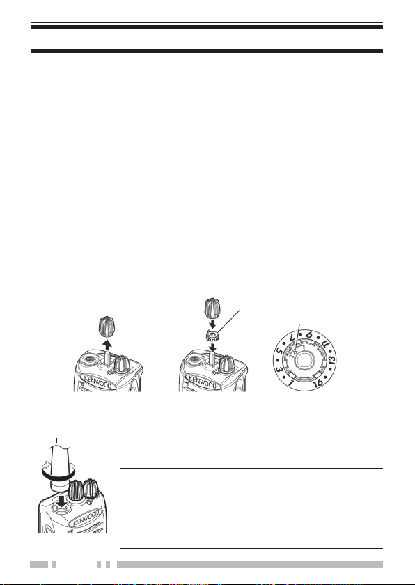
INSTALLING THE CHANNEL STOPPER
You can set the channel stopper position for channels 2, 4,
6, 8, 10, 12, and 14. Inserting the Channel stopper prevents
unnecessarily selecting channels which do not exist.
• Selecting a channel which does not exist causes a continuous error
tone to sound.
1 Set the Channel selector to channel 1, then pull the
Channel selector knob off the transceiver.
• If the Channel selector is not positioned at channel 1, the knob may
not install correctly and the channel may be unable to change.
2 Insert the channel stopper.
3 Set the arrow of the Channel stopper to the highest channel
number for the transceiver.
4 Reinsert the Channel selector knob.
Channel stopper
Arrow
INSTALLING THE ANTENNA
Antenna
2
Screw the antenna into the connector on the
top of the transceiver by holding the antenna at
its base and turning it clockwise until secure.
Note:
◆ The antenna is neither a handle, a key ring
retainer, nor a speaker/ microphone attachment
point. Using the antenna in these ways may
damage the antenna and degrade your
transceiver’s performance.
Page 11
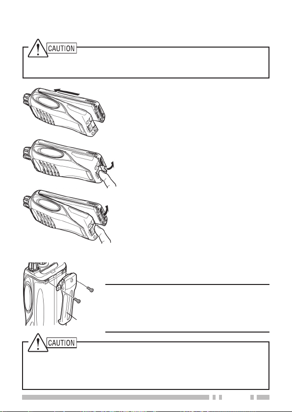
INSTALLING/ REMOVING THE BATTERY PACK
◆ Do not short the battery terminals or dispose of the battery by fi re.
◆ Never attempt to remove the casing from the battery pack.
1 Align the battery pack with the back
of the transceiver, then press the
battery pack and transceiver fi rmly
together until the release latch on
the base of the transceiver locks.
2 To remove the battery pack, lift the
safety catch on the base of the
transceiver, then press the release
latch underneath the safety catch.
3 While pressing the release latch,
pull the battery pack away from the
transceiver.
INSTALLING THE BELT CLIP
If necessary, attach the belt clip using the
two supplied M3 x 8 mm screws.
Note:
◆ If the belt clip is not installed, its mounting
location may get hot during continuous
Belt clip
transmission or when left sitting in a hot
environment.
Do not use glue which is designed to prevent screw loosening when
installing the belt clip, as it may cause damage to the transceiver. Acrylic
ester, which is contained in these glues, may crack the transceiver’s back
panel.
3
Page 12
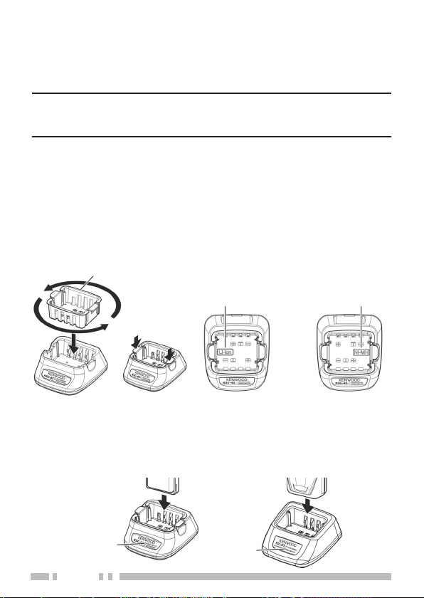
CHARGING THE BATTERY PACK (OPTIONAL BATTERY
CHARGER)
The battery pack is not charged at the factory; charge it before use.
ATTENTION:
◆ Always switch OFF a transceiver equipped with a battery pack
before inserting the transceiver into the charger.
1 Plug the AC adapter cable into the jack located on the rear
of the charger.
2 Plug the AC adapter into an AC outlet.
3 Match the Holder to the type of battery pack to be charged
so that when inserting the Holder, the battery type name
can be seen on the bottom of the charger. After inserting
the Holder into the charger, press the locking tabs to secure
it in place. <KSC-43 only>
Holder
• To remove the Holder, squeeze the locking tabs
together then pull the Holder out of the charger.
<KSC-43 only>
4 Slide a battery pack or a transceiver equipped with a
battery pack into the charging slot of the charger.
Li-ion battery
charger
Ni-MH battery
charger
Indicator
4
Indicator
Page 13

• Make sure the metal contacts of the battery pack mate securely
with the charger terminals.
• The indicator lights red and charging begins.
5 When charging is completed, the indicator lights green.
Remove the battery pack or the transceiver from the
charging slot of the charger.
• It takes approximately 3 hours to charge the battery pack.
• When the charger will not be used for a long time, unplug the
AC adapter from the AC outlet.
Note:
◆ When the indicator blinks red, the battery pack is either defective or
the battery pack contacts are not properly mated with those of the
charger.
◆ When the indicator fl ashes green and orange, the battery pack has
not satisfi ed the charging start temperature. Remove the battery
pack from the charger and wait until it reaches a normal temperature
before charging it again.
◆ The ambient temperature should be between 5°C and 40°C while
charging is in progress. Charging outside this range may not fully
charge the battery.
◆ The battery pack life is over when its operating time decreases even
though it is fully and correctly charged. Replace the battery pack.
INSTALLING THE CAP OVER THE SPEAKER/
MICROPHONE JACKS
Install the cap over the speaker/ microphone jacks when not
using an optional speaker/ microphone.
Note:
◆ To keep the transceiver water resistant, you must cover the
speaker/ microphone jacks with the supplied cap.
1 Place the cap over the jacks so that the locking tabs
insert into the transceiver grooves.
5
Page 14
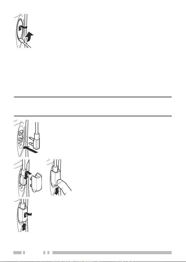
2 While holding the cap in place, push it towards the
bottom of the transceiver until the tabs on the cap click
into place.
• To remove the cap, hold the top of the cap in place
with your fi nger while inserting a 2 mm or smaller
fl at blade screwdriver under the bottom of the cap.
Slowly slide the screwdriver in until its tip touches
the tab inside the cap, then gently pry the cap
up (handle of screwdriver moving away from the
transceiver) to remove the cap.
INSTALLING THE OPTIONAL SPEAKER/ MICROPHONE
(OR HEADSET)
Note:
◆ The transceiver is not fully water resistant when using a speaker/
microphone or headset.
1 Insert the speaker/ microphone (or
headset) plugs into the speaker/
microphone jacks of the transceiver.
2 Place the locking bracket over the
speaker/ microphone (or headset) plugs
so that the locking tabs insert into the
transceiver grooves.
• Push down on the locking bracket to
slide it into place.
3 While holding the locking bracket in
place, push it towards the bottom of the
transceiver until the tabs on the bracket
click into place.
• To remove the locking bracket, push
the bracket up from the base.
6
Page 15
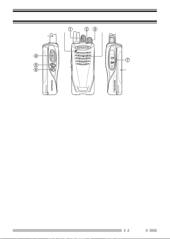
ORIENTATION
Microphone
Antenna
Speaker
Battery pack
a Channel selector
Rotate to change the operating channel.
b LED indicator
Refer to the LED indicator status. {p. 13}
c Power switch/ Volume control
Turn clockwise to switch ON the transceiver. To switch OFF
the transceiver, turn counterclockwise until a click sounds.
Rotate to adjust the volume level.
d PTT (Push to Talk) switch
Press and hold, then speak into the microphone to transmit.
e Side 1 key
Press to activate its programmable function. {page 8}
f Side 2 key
Press to activate its programmable function. {page 8}
g Speaker/ microphone jacks
Insert the Speaker/ microphone or Headset plug into this
jack. {page 6}
7
Page 16

PROGRAMMABLE AUXILIARY FUNCTIONS
Your dealer can program the Side 1 and Side 2 keys each with
one of the functions listed below.
Note:
◆ The duration of pressing a key to activate a function is dependent
on your dealer setting. Your dealer may have set some keys to
be held down for a short duration instead of being momentarily
pressed. Ask your dealer for details on which keys need to be
held down to activate their functions.
None
■
No function has been programmed.
Autodial
■
Autodial allows you to make a private DTMF call to another
party.
Call 1/ Call 2
■
Press to send a FleetSync status, NXDN status, NXDN
individual, 2-tone signaling call.
Calling Alert
■
A calling alert tone allows you to alert party members that
you are making a call. When making a call, fi rst hold down
this key.
• While holding down the key, the calling alert tone will sound.
CW Message
■
Press to transmit the preset Morse code message on your
current channel.
Emergency
■
Press and hold to enter (or exit) Emergency mode.
Key Lock
■
Press to lock/unlock the transceiver keys. Without Status
Memory, when the transceiver power is turned OFF and
then ON again, the Key Lock function will be canceled.
8
1
1
Release the key to end the tone, then hold down the PTT
switch and speak into the microphone to transmit.
2
Page 17

Key Lock with Status Memory
■
This operates the same as Key Lock except that when the
transceiver power is turned OFF and then ON again, the
keys remains locked.
Lone Worker
■
Lone Worker Mode is a safety feature built into the
transceiver. If the transceiver is not operated for a
pre-programmed period of time, the transceiver will emit a
tone and automatically enter Emergency operation. Press
this key to toggle the Lone Worker function ON or OFF.
Low Transmit Power
■
Each channel is programmed with either high or low
transmit power. On high transmit power channels, press this
key to change the transmit power to low power (you cannot
change low transmit power channels to use high power).
Monitor
■
Press to deactivate signaling (QT/DQT, FleetSync signaling,
NXDN, etc.). Press this key again to return to normal
operation.
Monitor Momentary
■
Continuously hold down this key to deactivate signaling
(QT/DQT, FleetSync signaling, NXDN, etc.). Release this
key to return to normal operation.
Paging Call
■
Press to send a FleetSync or NXDN paging call to an ID
from the ID list.
Priority Zone-Channel Select
■
If the scan priority type is “Operator Selectable”, press
this key in normal mode to set the current channel as the
Priority channel.
Scan
■
Press to start (or stop) scanning the transceiver channels.
9
Page 18

Scan Temporary Delete
■
When scan pauses at an undesired channel, you can
remove that channel from the scanning sequence by
pressing or holding this key.
Scrambler/Encryption
■
The Scrambler (analog) and Encryption (NXDN) function
allows you to hold a conversation in complete privacy. When
activated, any other party listening in on your channel will
be unable to understand your conversation. Press this key
to toggle the Scrambler/Encryption function ON or OFF.
Send the GPS data
■
With the KMC-48GPS unit is connected, you can press this
key to send your positioning data to the base station.
Squelch Off
■
1
Press to hear background noise. Press this key again to
return to normal operation.
Squelch Off Momentary
■
1
Continuously hold down this key to hear background noise.
Release this key to return to normal operation.
Talk Around
■
The Talk Around function allows you to communicate
directly with other transceivers, without the use of a
repeater. Press this key to toggle the Talk Around function
ON or OFF.
Zone Down
■
Press to select the previous zone.
Zone Up
■
Press to select the next zone.
1 Available only for Analog operation.
2 Available only for NXDN operation.
10
Page 19

BASIC OPERATIONS
SWITCHING POWER ON/OFF
Turn the Power switch/ Volume control clockwise to switch the
transceiver ON.
Turn the Power switch/ Volume control counterclockwise fully
to switch the transceiver OFF.
Transceiver Password
■
If your transceiver is password protected, the LED will light
blue when you turn the transceiver ON. Enter the password
(up to 4 digits) using the following procedure.
1 Set the Channel selector to position “1”.
2 Press the Side 1 or Side 2 key to enter the fi rst digit.
• The Side 1 key increases the digit value and the Side 2
key decreases it. The transceiver announces the digit
number as it changes.
3 Repeat step 2 for Channel selector positions 2 ~ 4.
• If there are less than 4 password digits, repeat for only the
number of digits the password contains.
4 Press the PTT switch to confi rm the password.
•
When the correct password is entered, the Blue LED turns off.
•
If you enter an incorrect password, an error tone sounds
and the transceiver remains locked.
ADJUSTING THE VOLUME
Rotate the Power switch/ Volume control to adjust the volume.
Clockwise increases the volume and counterclockwise
decreases it.
11
Page 20

SELECTING A ZONE AND CHANNEL
1 Select the desired zone using the key programmed as
[Zone Up] or [Zone Down].
• Each zone contains a group of channels.
2 Select the desired channel using the Channel selector.
• Each channel is programmed with settings for transmitting and
receiving.
TRANSMITTING
1 Select the desired zone and channel.
2 Press the key programmed as [Monitor] or [Squelch Off]
to check whether or not the channel is free.
• If the channel is busy, wait until it becomes free.
3 Press the PTT switch and speak into the microphone.
Release the PTT switch to receive.
• For best sound quality, hold the transceiver approximately
1.5 inches (3 ~ 4 cm) from your mouth.
RECEIVING
Select the desired zone and channel. If signaling has been
programmed on the selected channel, you will hear a call only
if the received signal matches your transceiver settings.
Note:
◆ Signaling allows your transceiver to code your calls. This
will prevent you from listening to unwanted calls. Refer to
“SIGNALING” {p. 17} .
12
Page 21

LED INDICATOR STATUS
Indicator Color Meaning
Flashes blue Digital mode
Flashes orange Analog mode
Lights red Transmitting
Lights green Receiving a call
Blinks red Battery power is low while transmitting
Blinks green Scanning & site roaming
Blinks orange
or blue *
Blinks red/orange
* Your dealer can set the LED to blink either orange or blue for
FleetSync, DTMF, 2-tone, or NXDN operation.
Receiving an encoded call (FleetSync
signaling, etc.)
The selected channel has not been
programmed and cannot be used.
VOICE OPERATED TRANSMISSION (VOX)
VOX operation allows you to transmit hands-free. This feature
must fi rst be activated by your dealer, and can only be used if
you are using a supported headset. VOX can be turned off for
specifi c channels by your dealer. To activate VOX and set the
VOX Gain level, perform the following steps:
1 Connect a headset to the transceiver.
• The VOX function does not activate when a headset is not
connected to the accessory terminal of the transceiver.
2 With the transceiver power OFF, press and hold the Side 1
key while turning the transceiver power ON.
3 Continue to hold the Side 1 key until a beep sounds.
• The LED indicator lights orange.
• When the Side 1 key is released, the transceiver will announce
the VOX Gain level.
13
Page 22

4 Press the Side 1 key to set the VOX Gain level, from OFF, 1
(least sensitive) to 10 (most sensitive).
• Press the Side 2 key to enable or disable the VOX function for the
current channel (you can change this setting for each channel by
selecting a channel with the Channel selector). When turned ON,
a beep sounds. When turned OFF, a double beep sounds.
• When the sector points to empty channel, pressing Side 2 key will
cause the error tone to sound.
5 Press the PTT switch to save the setting.
• A beep will sound.
• The transceiver announces the new VOX Gain level.
6 Turn the transceiver power OFF and then ON again to
activate VOX.
7 If transceiver password mode is set, the user need to key in
the correct password before entering the VOX setup mode.
Note:
◆ If key lock with status memory is ON, you will be unable to enter
VOX setup mode.
◆ If a headset is connected to the transceiver while the VOX function
is switched ON and the VOX Gain level is confi gured to a higher,
more sensitive level, louder received signals may cause the
transceiver to start transmitting.
◆ If no operation is performed for 20 seconds, the transceiver will exit
VOX setup mode.
14
Page 23

NXDN
NXDN is a general term for the NXDN wireless communication
protocol which uses 4 Level FSK. Various data communications,
including individual and group voice communications, Status
calls, and GPS data transmission, are possible.
INDIVIDUAL/GROUP CALLS
Each channel is set up with an individual or group ID list number.
To make a call, select the channel with the ID list number you
wish to call, then press the PTT switch to start the call.
• Your dealer may also have set Selcall on PTT for Individual or
Group calls, allowing you to make an Individual or Group call when
pressing the PTT switch.
• To page the target transceiver instead of initiating a voice call,
press the key programmed as [Paging Call].
• If PTT Proceed tone is enabled, the Proceed tone will sound. After
the tone ends, you can begin the call.
Receiving
■
When you receive an individual call, a ringing tone will
sound. Respond to the call by pressing the PTT switch.
• If the auto reset timer expires before you respond to the call,
the call will end. Your dealer can set the duration for the auto
reset timer (default is 10 seconds).
When you receive a group call and the received group ID
matches the ID set up on your transceiver, a ringing tone
will sound and you can hear the caller’s voice.
STATUS CALL
You can transmit your status (preset by your dealer) to the
target transceiver by pressing the key programmed as [Call 1]
or [Call 2], if they have been set up with an NXDN Status.
• Channels are set up with ID list numbers by your dealer. Select the
desired channel before sending the status call.
15
Page 24

BACKGROUND OPERATIONS
TIME-OUT TIMER (TOT)
The Time-out Timer prevents callers from using a channel
for an extended duration. If you continuously transmit for the
duration programmed by your dealer (default is 1 minute),
transmission will stop and a warning tone will sound. To stop
the tone, release the PTT switch.
BATTERY SAVER
When activated by your dealer, the Battery Saver function
decreases the amount of power used after no signal is present
and no operations are being performed for 5 seconds. When a
signal is received or an operation is performed, Battery Saver
turns off.
Note:
◆ While the Battery Saver is operating, the LED may fl ash green
when receiving a QT/DQT signal which does not match the QT/
DQT tone/code set up in your transceiver.
LOW BATTERY WARNING
While operating the transceiver, the Low Battery Warning
sounds until the PTT switch is released and the LED indicator
blinks red when the battery needs recharged or replaced.
BUSY CHANNEL LOCKOUT (BCL)
When activated, BCL prevents you from interfering on a
channel that is already in use. Pressing the PTT switch will
cause an alert tone to sound and the transceiver will not
transmit. Release the PTT switch to stop the tone.
Note:
◆ Ask your dealer for an explanation on how BCL functions when
using QT, DQT, RAN, or Optional signaling.
16
Page 25

If BCL Override has been programmed, you can transmit over
the current signal:
1 Press and hold the PTT switch.
• If the channel is already in use, a warning tone will sound.
2 Quickly release and then press the PTT switch again.
3 Speak into the transceiver as you would during a normal call.
PTT ID
PTT ID is the transceiver unique ID code which is sent each
time the PTT switch is pressed and/or released.
Note:
◆ PTT ID can be made only in analog operation.
SIGNALING
QT/ DQT
■
The Encoder/Decoder function uses QT/ DQT to segregate
talk groups, so users only hear calls from their own group.
Radio Access Number (RAN)
■
RAN is a signaling system designed for digital radio
communications. When a channel is set up with a RAN,
squelch will only open when a call containing a matching
RAN is received. If a call containing a different RAN is
made on the channel you are using, you will not hear the
call. This allows you to ignore (not hear) calls from other
parties who are using the same channel.
NXDN ID
■
NXDN ID is an optional signaling system available only for
digital communications.
DTMF
■
A DTMF PTT ID is included for dispatch operations or
simple remote control applications. The DTMF decode
capabilities include Selective Call ID, Transpond with ID,
and “Wild Card” Group Calling.
17
Page 26

2-Tone
■
2-tone Signaling opens the squelch only when your
transceiver receives a call containing matching 2 tones.
FleetSync
■
Utilizing JVC KENWOOD’s FleetSync digital signaling
protocol, this transceiver has PTT ID and Selective
Calling capabilities for managed dispatch operations. For
hazardous/hostile duty environments, the Side1 or Side 2
key can be programmed for Emergency status to alert the
dispatcher and/or operator in distress.
MDC-1200
■
The following features are available with the built-in MDC
signaling: PTT ID Encode, Emergency Encode, Stun/Revive
Decode, and Radio Check Decode.
Note:
◆ The transceiver cannot decode MDC-1200 when the
respective channel incorporate any FleetSync properties.
(example: PTT-ID, Optional signaling).
COMPANDER
If programmed by your dealer for a channel, the compander will
remove excessive noise from transmitted signals, to provide
higher clarity of signals.
Note:
◆ The compander is used only in analog operation.
VOICE ANNUNCIATION
If enabled by your dealer, when changing the zone and
channel, an audio voice will announce the new zone and
channel number.
18
Page 27

使用说明书
VHF
数字模拟双模手持对讲机
NX-248
UHF
数字模拟双模手持对讲机
NX-348
使用之前请阅读以下信息:
使用产品前请仔细阅读本使用说明书,
并请妥善保管。
© B5A-0068-10 (C)
Page 28

出版日 :
2015年1月1
日
Page 29

鸣谢惠购
感谢您选择 KENWOOD 产品用于您的陆地移动无线电应用。
本使用说明书仅包含该 NEXEDGE 便携式无线电设备的基本操作。
对于设备上可能添加的定制化功能, 请咨询经销商。
用户注意事项
政府法律禁止在政府控制的区域内使用未经当局许可的无线电
◆
发射机。
非法使用将会受到罚款或监禁处罚。
◆
只能由有资格的技术人员进行维修。
◆
安全性 : 操作人员应该知道并了解对讲机操作的一般危险。
本产品所包含的 A M B E +2
知识产权 ( 包括专利权、 版权和贸易机密 ) 的保护。
该语音编码技术仅许可用于本通信设备。 该技术的使用人员明
确禁止尝试提取、 移除、 破译、 反向编译或拆除目标代码,
或以其他方式将目标代码转换为人类可读形式。 美国专利编号
# 5,826,222、# 5,754,974、# 5,701,390、 以及# 5,715,365。
固件版权
建伍公司保留建伍产品存储器内嵌固件的产权和版权的所有权。
T M
语音编码技术受 Digital Voice System, Inc.
i
Page 30

ii
Page 31

注意事项
• 对讲机和电池潮湿时请勿对其充电。
• 对讲机和电池之间应确保无金属物品。
• 请勿使用非 KENWOOD 指定的选件。
• 如果压铸底盘和对讲机的其他部件损坏, 请勿接触损坏的部件。
• 如果头戴式耳麦或头戴耳机连接到对讲机上, 请减小对讲机的音
量。 当打开静噪时, 一定要注意音量。
• 靠近各种机械和电器时, 请勿将麦克风电缆挂在颈部周围, 因为
机械和电器可能会使电缆缠住。
• 请勿将对讲机放置在不稳定的表面上。
• 应确保天线的末端不会碰到您的眼睛。
• 对讲机长时间用于发射时, 散热器和底座会变热。 更换电池时,
请勿接触这些位置。
• 请勿将对讲机浸入水中。
• 安装选件前, 一定要关闭对讲机的电源。
• 充电器是将装置与交流电源线断开的设备。 应随时提供交流插头。
iii
Page 32

䆜
在下列场合要关闭对讲机的电源 :
• 易爆环境 (易燃气体、 粉尘、 金属粉末以及粒状粉末等)。
• 加油时或停在加油站时。
• 在易爆场所附近。
• 在飞机上。(对讲机的使用必须遵循机组人员的指示和规定。)
• 在粘贴有关于无线电设备的限制或警告的场合, 包括但不限于
医疗设施。
• 在使用心脏起搏器的人员附近。
⌞ᝅ
• 请勿因任何理由拆卸或改装对讲机。
• 汽车正在行驶时, 请勿将对讲机放在安全气囊上或其附近。 安
全气囊打开时, 对讲机可能会弹出, 击中驾驶员或乘客。
• 当接触天线端时或天线罩露出任何金属部件时, 请勿发射。 此
时发射可能会引起高频灼伤。
• 如果对讲机发出异常气味或冒烟, 请立即关闭对讲机的电源,
从对讲机中取出电池, 并与 KENWOOD 经销商联系。
• 驾车时使用对讲机可能违反交通方面的法律。 请查阅并遵守您
所在地区的驾车法规。
• 请勿将对讲机暴露于极热或极冷的气候条件下。
• 请勿将电池 (或电池盒) 与金属物体放在一起携带, 因为金
属物体可能会使电池端子短路。
• 如果更换的电池不正确, 会有爆炸的危险。 请务必更换相同类
型的电池。
• 如果使用市场销售的脖子挂件时, 请注意不要让挂件被附近的
机器夹住。
• 在空气干燥地区操作对讲机时容易产生电荷 (静电)。 当在这
样的情况下使用耳机附件时, 可能会使对讲机通过耳机与您的
耳朵之间发生放电。 在这种场合下我们建议您只使用扬声器/
麦克风, 以避免放电。
• 请遵从国家或地方的有关法律法规废弃电池。
iv
Page 33

有关电池组的信息 :
电池含有有机溶剂等易燃物体。 错误操作可能会造成电池裂开, 从而
着火或产生过热, 使电池失效或造成电池其它形式的损坏。
ধ䲟
• 请勿拆卸或改造电池!
电池具有保护功能以及一个保护电路, 防止危险。 若遭受严重
损坏, 电池可能会产生热量或烟雾、 破裂、 或起火。
• 请勿造成电池短路!
请勿使用任何金属 (如回形针或电线) 连接 + 极和 – 极。 请
勿用装金属物体 (如电线、 链式项链或发夹) 的容器放置或
储存电池。 如果电池短路, 将会产生过大电流, 电池可能会
发热或冒烟、 破裂或着火。 还将造成金属物体发热。
• 请勿焚烧或加热电池!
若绝缘体熔化, 则气体排放出口或安全功能会受损, 或者若电
解液点燃, 电池可能会产生热量或烟雾、 破裂或起火。
• 请勿将电池放置在火、 炉或其他发热器附近 (达到 80°C 以上
的区域) 或在上述环境下使用电池!
如果聚合物隔离器由于高温而熔化, 个别电池可能会内部发生
短路, 电池可能会产生热量或烟雾、 破裂或起火。
• 避免将电池浸入水中或通过其他方式将其弄湿!
如果电池潮湿, 使用前用干燥的毛巾将其擦干。 如果电池保护
电路受损, 电池可能会在过大电流 (或电压) 下充电, 可能
会发生异常化学反应。 电池可能会产生热量或烟雾、 破裂或起
火。
• 请勿在炉火或直接阳光照射下给电池充电!
如果电池保护电路受损, 电池可能会在过大电流 (或电压)
下充电, 可能会发生异常化学反应。 电池可能会产生热量或烟
雾、 破裂或起火。
• 仅使用规定的充电器并遵守充电要求!
如果电池在规定以外的条件下 (超过规定值的高温, 超高压或
超过规定值的电流条件下, 或者使用改造过的充电器) 充电,
可能会过充或可能会发生异常化学反应。 电池可能会产生热量
或烟雾、 破裂或起火。
• 请勿用任何物体刺入电池、 用工具打击或踩踏电池!
这有可能破坏电池或使电池变形, 造成短路。 电池可能会产生
热量或烟雾、 破裂或起火。
v
Page 34

ধ䲟
• 请勿震动或抛扔电池!
一次冲击可能会造成电池泄露、产生热量或烟雾、破裂或起火。
如果电池保护电路受损, 电池可能会在过大电流 (或电压)
下充电, 可能会发生异常化学反应。
• 若电池损坏, 请勿使用!
电池可能会产生热量或烟雾、 破裂或起火。
• 请勿直接在电池上焊接!
如果绝缘体熔化、 或气体排放出口或安全功能受损, 电池可能
会产生热量或烟雾、 破裂或起火。
• 请勿颠倒电池极性 (和端子) !
当反向给电池充电时, 可能会发生异常化学反应。 在某些情况
下, 放电时可能会有大的意想不到的电流流过。 电池可能会产
生热量或烟雾、 破裂或起火。
• 请勿反向给电池充电或反向连接!
电池具有正负极。 如果电池未能轻易地与充电器或操作设备连
接, 请勿强迫连接 ; 检查电池极性。 如果电池反向连接到充电
器上, 将会反向充电, 可能会发生异常化学反应。 电池可能
会产生热量或烟雾、 破裂或起火。
• 请勿接触破裂以及漏液的电池!
如果电池电解液流入眼中, 尽快用清水冲洗眼睛, 不得揉擦眼
睛。立即去医院救治。 如果未及时处理,可能会造成眼部疾病。
䆜
• 电池充电请勿超过规定的时间!
如果超过规定时间后电池还在充电, 请立即停止充电。 电池可
能会产生热量或烟雾、 破裂或起火。
• 请勿将电池放入微波容器或高压容器中!
电池可能会产生热量或烟雾、 破裂或起火。
• 请将破裂和泄露的电池远离明火!
如果电池发生泄露 (或电池发出难闻的气味), 立即将其远离易
燃区。 电池中的电解液泄露能轻易引发火灾, 并可能会产生热量
或烟雾、 破裂或起火。
• 请勿使用异常电池!
如果电池散发出难闻的气味、 看起来颜色发生变化、 变形或由
于其他原因而看起来异常, 将其与充电器或操作设备断开并不
再使用。 电池可能会产生热量或烟雾、 破裂或起火。
vi
Page 35

目录
拆开包装箱并检查设备 .......................................................1
准备工作 ............................................................................. 2
介绍 .................................................................................... 7
可编程辅助功能 .................................................................. 8
基本操作 ........................................................................... 11
声控发射 (VOX) ................................................................14
NXDN ............................................................................... 15
后台操作 ........................................................................... 16
拆开包装箱并检查设备
小心拆开通信机的包装。如果下列物品有缺失或损坏,请立即向
承运人提出书面要求。
随机附件
• 天线 (NX-348附带。) ........................................................................ 1
• 扬声器/麦克风插孔盖 ..................................................................... 1
• 扬声器/麦克风锁定架 ..................................................................... 1
• 皮带夹(KBH-10) ............................................................................. 1
• 螺丝(M3 x 8 mm) ............................................................................ 2
• 信道止动器 ...................................................................................... 1
• 使用说明书 ...................................................................................... 1
注:
◆ 有关配件安装说明,请参阅第2页上的“准备工作”。
1
Page 36

准备工作
安装信道止动器
您可以为信道2、4、6、8、10、12和14设置信道止动器位
置。插入信道止动器可防止意外选择不存在的信道。
• 选择不存在的信道可导致发出连续的出错提示音。
1 将信道开关置于信道1的位置,然后将信道开关旋钮从通信
机中抽出。
• 如果信道开关不在信道1的位置,说明旋钮可能安装不正
确,此时可能无法调换信道。
2 插入信道止动器。
3 将信道止动器的箭头置于通信机的最高信道号处。
4 重新插入信道开关旋钮。
信道止动器
箭头
安装天线
天线
握住天线底座并顺时针转动,直至拧紧,以此
将天线固定到通信机顶端的连接器上。
注:
◆ 不能将天线用作把手、钥匙环挡圈或扬声器/麦
克风的安装点。作为上述用途使用时,可能会损
坏天线或降低通信机的性能。
2
Page 37

安装/拆卸电池组
⌞ᝅ
◆ 请勿短接电池端子或用焚烧方式处置电池。
◆ 切勿尝试除掉电池组的外壳。
1 将电池组与通信机的背部对准,然
后按压电池组使其与通信机贴紧,
直至通信机底座上的释放锁牢牢锁
定就位。
2 若要取出电池组,请上提通信机底
座上的安全锁,然后按压安全锁下
面的释放锁。
3 在按住释放锁的同时,将电池组从
通信机中抽出。
安装皮带夹
必要时,请利用附带的两颗M3 x 8 mm
螺丝安装皮带夹。
注:
◆ 如果不安装皮带夹,在连续发射或长时
间置于炎热环境的情况下,其安装位置
可能会变热。
皮带夹
⌞ᝅ
安装皮带夹时, 切勿使用胶水来防止螺丝松脱, 否则可能导致通信机损
坏。 胶水中所含的丙烯酸酯会引起通信机的后面板开裂。
3
Page 38

对电池组充电 (可选电池充电器)
电池组在出厂时未充电。使用前请为其充电。
注:
◆ 在将装有电池组的通信机插入充电器之前,务必先关闭通信机电源。
1 将电源适配器电缆插入充电器背面的插孔中。
2 将电源适配器插入交流电源插座中。
3 根据被充电电池的类型安装支架。可以在充电器底面看到电
池类型的名称。将支架插入充电器后,按下锁定卡以确保支
架固定在充电器上。<KSC-43只>
支架
锂离子(Li-ion)
电池充电器
•
取支架时,向内按压两侧的锁定卡,然后从充电器上取出
镍氢(Ni-MH)电
池充电器
支架。<KSC-43只>
4
将电池组或装有电池组的通信机滑入充电器的充电插槽中。
指示灯
指示灯
• 确保电池组的金属触点与充电器端子牢牢啮合在一起。
• 指示灯将亮红色,充电开始。
5 充电结束时,指示灯将亮绿色。将电池组或通信机从充电器
的充电插槽中取出。
4
Page 39

• 对电池组充电大约需要3小时的时间。
• 如果打算很长时间不使用充电器,请将电源适配器从交流电
源插座上拔下。
注:
◆ 当指示灯闪烁红色时,说明电池组损坏,或者电池组触点未与充
电器端子正确啮合。
◆ 当指示灯闪烁绿色和橙色时,说明尚未满足电池组的充电起始温
度要求。请将电池组从充电器中取出,稍候片刻,待恢复正常温
度后再重新进行充电。
◆ 充电过程中,环境温度应在5˚C到40˚C之间。在上述温度范围之
外充电可能会导致无法完全充电。
◆ 如果在完全充电的情况下出现操作时间缩短的情况,说明电池组
的寿命已尽。请更换电池组。
安装扬声器/麦克风插孔盖
不使用扬声器/麦克风选件时,请安装扬声器/麦克风插孔盖。
注:
◆ 为保持通信机的防水效果,请务必用随带的插孔盖将扬声器/麦克
风插孔盖好。
1 盖好插孔盖,使锁定突起插入通信机凹槽内。
2 将插孔盖放好,然后向通信机底端方向按压,直
至插孔盖上的突起咔哒一声就位。
• 若要取下插孔盖,请用手指握住插孔盖的顶
端,同时在插孔盖的底部插入一把厚度不超过
2 mm的平刃螺丝刀。将螺丝刀缓慢滑入,直
至其尖端触及插孔盖内的突起,然后轻轻将插
孔盖上撬(螺丝刀的手柄向通信机外移动),
从而将插孔盖取下。
5
Page 40

安装扬声器/麦克风选件(或头戴式耳机)
注:
◆ 使用扬声器/麦克风或头戴式耳机时,通信机不具备完全防水性能。
1 将扬声器/麦克风(或头戴式耳机)
插头插入通信机的扬声器/麦克风插
孔中。
2 将锁定架置于扬声器/麦克风(或头
戴式耳机)插头上,使锁定突起插入
通信机凹槽内。
• 下压锁定架,将其滑入就位。
3 将锁定架放好,然后向通信机底端方
向按压,直至锁定架上的突起咔哒一
声就位。
• 若要取下锁定架,请沿底座上推
锁定架。
6
Page 41

介绍
麦克风
天线
扬声器
电池组
a 信道开关
旋转可切换工作信道。
b LED指示灯
有关LED指示灯的状态,请参阅第13页。
c 电源开关/音量控制
顺时针转动可打开通信机电源。若要关闭通信机电源,请逆
时针转动,直至听到咔哒声。旋转可调整音量。
d PTT(按下通话)开关
按住此开关并对着麦克风讲话,即可进行发射。
e 侧面按键1
按下可启动其可编程功能{第8页}。
f 侧面按键2
按下可启动其可编程功能{第8页}。
g 扬声器/麦克风插孔
将扬声器/麦克风插头或头戴式耳机插头插入该插孔中{第6
页}。
7
Page 42

可编程辅助功能
经销商可分别将侧面按键1和侧面按键2设置为以下所列的功能
之一。
注:
◆ 激活功能所需的按键时间与经销商的设置有关。有些键可能被经销
商设置为按住片刻,而非快按。有关哪些键需要按住才能激活相应
功能的详情,请向经销商咨询。
■ 无
未设置功能。
■ 自动拨号
自动拨号允许您对另一方进行DTMF私密呼叫。
■ 呼叫 1/ 呼叫 2
按下可发送FleetSync状态、NXDN状态、NXDN单呼、2-音
信令呼叫。
■ 呼叫提示
呼叫提示音用于提醒其他各方您在进行呼叫。进行呼叫时,
请先按住此键。
• 按住此键时,将发出呼叫提示音。松开此键将结束停止
■ CW 信息
按下可发射当前信道上的预设摩尔斯电码信息。
■ 紧急报警
按住可进入(或退出)紧急报警模式。
■ 键盘锁定
按下可锁定/解锁通信机上的按键。不带状态记忆时,当关闭
然后重新打开通信机电源时,键盘锁定功能将被取消。
■ 带状态记忆的键盘锁定
与键盘锁定功能基本相同,区别在于:当关闭然后重新打开
通信机电源时,键盘仍保持锁定状态。
1
1
提示音,此时按住PTT开关并对着麦克风讲话,即可进行
发射。
2
8
Page 43

■ 单独工作者
单独工作者模式是通信机内置的一项安全功能。如果在预设
的时间段内未操作通信机,通信机就会发出提示音并自动转
入紧急报警操作。按下此键可以打开/关闭单独工作者功能。
■ 低发射功率
每个信道都会被设置为高发射功率或低发射功率。在高发射
功率信道上,按此键将切换为低发射功率(无法将低发射功
率信道切换为高发射功率)。
■ 监听
按下可停用信令(QT/DQT、FleetSync信令、NXDN等)。
再次按此键将返回正常操作状态。
■ 瞬时监听
按住此键可停用信令(QT/DQT、FleetSync信令、NXDN
等)。松开此键将返回正常操作状态。
■ 寻呼
按下可将FleetSync或NXDN寻呼发送至ID列表中的某个ID。
■ 优先区域信道选择
如果扫描优先类型为“操作者可选”,则在常规模式下按此
键就会将当前信道设为优先信道。
■ 扫描
按下将开始(或停止)扫描通信机信道。
■ 扫描暂时删除
当扫描暂停在不需要的信道上时,可通过按下或按住此键将
此信道从扫描序列中删除。
■ 扰频器 / 加密
扰频器(模拟)和加密(NXDN)功能允许在完全私密的状态
下进行通话。激活后,信道上的其他各方将无法听清您的通
话。按下此键可以打开/关闭扰频器/加密功能。
■ 发送 GPS 数据
在连接KMC-48GPS装置的情况下,按下此键可将位置数据发
送至基站。
9
Page 44

■ 静噪打开
1
按下可听到背景噪音。再次按此键将返回正常操作状态。
■ 瞬时静噪打开
1
按住此键可听到背景噪音。松开此键将返回正常操作状态。
■ 脱网通信
脱网通信功能允许在不使用中继器的情况下直接与其他通信
机对话。按下此键可以打开/关闭脱网通信功能。
■ 区域下调
按下可选择下一区域。
■ 区域上调
按下可选择上一区域。
1 仅可用于模拟操作。
2 仅可用于NXDN操作。
10
Page 45

基本操作
切换电源开/关
顺时针转动电源开关/音量控制可打开通信机电源。
逆时针将电源开关/音量控制转到底可关闭通信机电源。
■ 通信机密码
如果通信机有密码保护,则在打开通信机电源时,LED将亮
蓝色。请按以下步骤输入密码(最多4个数字):
1 将信道开关置于位置“1”。
2 按侧面按键1或侧面按键2,输入第一个数字。
• 侧面按键1用于增大数值,侧面按键2用于减小数值。
数值改变时,通信机会播报相应的值。
3 对信道开关的位置2 ~ 4,重复步骤2。
• 如果密码的位数小于4,则仅对密码中所含的位数重
复上述操作。
4 按PTT开关,确认密码。
• 如果输入的密码正确无误,蓝色LED就会熄灭。
• 如果输入错误密码,通信机将发出出错提示音并且保
持锁定状态。
音量调节
旋转电源开关/音量控制可调节音量。顺时针旋转可提高音量,
逆时针旋转则降低音量。
11
Page 46

选择区域和信道
1 利用设置为[区域上调]或[区域下调]的键选择想要的区域。
• 每个区域可包含多个信道。
2 利用信道开关选择想要的信道。
• 每个信道均可进行发射和接收设置。
发射
1 选择想要的区域和信道。
2 按下设置为[监听]或[静噪打开]的键,检查信道是否空闲。
• 如果信道繁忙,请等待直至信道空闲。
3 按PTT开关并对着麦克风讲话。松开PTT开关将转换到接收
状态。
• 为获得最佳的音质,嘴和麦克风之间应保持约3~4厘米
的距离。
接收
选择想要的区域和信道。如果在所选信道上设置了信令,则只有
在接收到符合通信机设置的信令时,您才能听到呼叫。
注:
◆ 信令允许通信机对呼叫进行编码。这样可以避免听到不想要的呼
叫。详情请参阅第17页上的“信令”。
12
Page 47

LED指示灯状态
指示灯颜色 含义
闪烁蓝色 数字模式
闪烁橙色 模拟模式
亮红色 正在发射
亮绿色 正在接收呼叫
闪烁红色 发射时电池电量不足
闪烁绿色 正在扫描
闪烁橙色或蓝色* 正在接收编码后的呼叫(FleetSync信令等)
闪烁红色/橙色 尚未设置或无法使用所选的信道。
* 经销商可以将FleetSync、DTMF、2音或NXDN操作所对应的
LED设置为闪烁橙色或蓝色。
13
Page 48

声控发射(VOX)
VOX(声控)操作允许进行免提发射。该功能必须先由经销商
激活,且仅在使用支持的头戴式耳机时才可用。经销商可以关闭
特定信道的VOX功能。若要激活VOX并设置VOX增益电平,请
执行以下操作:
1 将头戴式耳机连接至通信机。
• 当头戴式耳机未连接至通信机的配件端子时,不会激活
VOX功能。
2 在关闭通信机电源的情况下,请在按住侧面按键1的同时打
开通信机电源。
3 继续按住侧面按键1,直至听到哔音。
• LED指示灯将亮橙色。
• 松开侧面按键1时,通信机会播报VOX增益电平的值。
4 按侧面按键1,在关闭或 1(最低灵敏度)到10(最高灵敏
度)之间设置VOX增益电平。
• 按侧面按键2可启用或禁用当前信道的VOX功能(通过用
信道开关选择信道,可以更改相应信道的此项设置)。启
用时,会听到一声哔音。禁用时,会听到两声哔音。
• 当扇区指向空信道时,按侧面按键2会发出出错提示音。
5 按PTT开关,保存设置。
• 此时可听到一声哔音。
• 通信机会播报新VOX增益电平的值。
6 关闭并重新打开通信机电源,从而激活VOX。
7 如果设置了通信机密码模式,用户必须输入正确的密码才能
进入VOX设置模式。
注:
◆ 如果带状态记忆的键盘锁定功能处于打开状态,则无法进入VOX设置
模式。
◆ 在打开VOX功能的情况下,如果通信机上连接有头戴式耳机,而且
VOX增益电平设为高灵敏水平,则过大声音的接收信号可导致通信机
开始发射。
◆ 如果20秒内未执行任何操作,通信机就会退出VOX设置模式。
14
Page 49

NXDN
NXDN是使用4级FSK技术的NXDN无线通信协议的总称。它支持
各种数据通信,包括单呼和组呼、状态呼叫及GPS数据传送。
单呼/组呼
每个信道都会设置单呼或组呼ID列表号。呼叫时,请选择带有所
要呼叫的ID列表号的信道,然后按PTT开关开始呼叫。
• 经销商可能在PTT上还为单呼或组呼设置了选择呼叫功能,
用于在按下PTT开关时进行单呼或组呼。
• 若要寻呼目标通信机,而非启动语音呼叫,请按下设置为[寻
呼]的键。
• 如果启用了“PTT Proceed”提示音功能,就会发出进行音。
进行音结束后,即可进行呼叫。
接收
■
接收到单呼时,会响起振铃。若要响应呼叫,请按PTT开
关。
• 如果在响应呼叫前自动复位定时器已失效,呼叫就会终
止。经销商可以设置自动复位定时器的有效时间(默认
为10秒)。
当接收到组呼且接收到的组ID与通信机设置的ID匹配时,就
会响起振铃并听到呼叫者的声音。
状态呼叫
在设置NXDN状态功能的情况下,按下设置为[呼叫1]或[呼叫2]
的键可将您的状态(由经销商预设)发送至目标通信机。
• 信道的ID列表号由经销商设置。请在发送状态呼叫前选择想
要的信道。
15
Page 50

后台操作
超时定时器(TOT)
超时定时器可以防止呼叫者过久地使用某一信道。如果连续发射
超过了经销商设置的时间(默认为1分钟),就会停止发射并发
出警告提示音。若要停止提示音,请松开PTT开关。
电池省电
被经销商激活后,电池省电功能可以减少在5秒钟内未接收到信
号及未执行操作时的耗电量。再次接收到信号或执行操作时,将
会关闭电池省电功能。
注:
◆ 启动电池省电功能后,当接收到与通信机中设置的QT/DQT音频/代
码不匹配的QT/DQT信号时,LED可能会闪烁绿色。
电池不足警告
操作通信机时,如果电池需要重新充电或更换,就会响起电池不
足警告提示音,直至松开PTT开关,且LED指示灯闪烁红色。
繁忙信道锁定(BCL)
激活后,BCL功能可以防止您干扰已在使用中的信道。此时按
PTT开关会发出提示音,且通信机不会发射。松开PTT开关将停
止提示音。
注:
◆ 有关在使用QT、DQT、RAN或可选信令时BCL所发挥的作用的说
明,请向经销商咨询。
16
Page 51

如果已设置为“忽略BCL”,则可在当前信号上进行发射:
1 按住PTT开关。
• 如果该信道已在使用中,则会发出警告提示音。
2 快速松开然后再次按住PTT开关。
3 像在常规呼叫期间那样对着通信机讲话。
PTT ID
PTT ID是通信机特有的ID代码,每次按下和/或松开PTT开关时
将发送该代码。
注:
◆ PTT ID仅可用于模拟操作。
信令
■ QT/ DQT
编码器/解码器功能使用QT/DQT来隔离通话组,因此用户只
能听到自己组的呼叫。
■ 无线电接入号 (RAN)
RAN是一种设计用于数字无线电通信的信令系统。当信道设
置RAN时,只有在收到包含匹配RAN的呼叫时才会打开静
噪。如果在所用的信道上进行含有不同RAN的呼叫,则不会
听到此呼叫。这样即可忽略(听不到)来自正在使用同一信
道的其他人的呼叫。
■ NXDN ID
NXDN ID是一个可选信令系统,仅可用于数字通信。
■ DTMF
调度操作或简单远程控制应用程序中会附带DTMF PTT
ID。DTMF解码功能包括选择呼叫ID、转发ID及“通配”组
呼。
17
Page 52

■ 2- 音
只有当通信机收到包含匹配的2音的呼叫时,2-音信令才会打
开静噪。
■ FleetSync
借助JVC KENWOOD的FleetSync数字信令协议,该通信机为
管理调度操作设置了PTT ID及选择呼叫功能。对于危险/恶劣
的作业环境,可以将侧面按键1或侧面按键2设置为紧急报警
状态,用于提醒调度员和/或操作员保持警惕。
■ MDC-1200
通过内置MDC信令可以使用以下功能:PTT ID编码、紧急报
警编码、遥毙/复活解码、无线电通信检查解码。
注:
◆ 当相应信道包含了任何FleetSync属性时,通信机将无法对MDC
1200进行解码。
(例如,PTT-ID,可选信令)
压扩器
如果经销商针对某一信道进行了编程,压扩器将从发射的信号中
去除多余的噪音,从而提供更清晰的信号。
注:
◆ 压扩器仅可用于模拟操作。
语音通告
被经销商启用后,当更改区域和信道时,有一个语音将播报新的
区域和信道号。
18
 Loading...