

Kenwood KX-W791 Instruction Manual

STEREO
CASSETTE
TAPE
DECK
KX-\A/791
INSTRUCTION
MANUAL
KENWOOD
CORPORATION
B6O-0387-OO@(K, P, M, X, Y)E
92/121110 I I
7
6 5 4 3
21
9't/12
r
lntroduction
Your
choice
of
this
product
indicates that
you
are a devotee
to excellence in sound reproduction.
We
appreciate
your patronage
and
take
pride
in the long
tradi-
tion of
quality
components
that our company represents.
So that
you
can
get
the most
out of
your
unit, we
suggest that
you
take the time to read through this manual
before
you
hook
up
and operate
your
system. This will
acquaint
you
with
oper-
ating features and system-connection
considerations so that
your
listening
pleasure
will
be enhanced right from
the start.
You
will
notice
that
in
all aspects
of
planning,
engineering,
styling.
operating convenience and adaptability we have
sought
to anticipate
your
needs
and desires.
Keep this manual handy for future
reference.
For
your
records
Record
the serial
number.
found on the back
of
the
unit,
in
the spaces designated
on the warranty card, and in the space
provided
below.
Refer
to the model and serial numbers
whenever
you
call upon
your
dealer for information or service
on
this
product.
Model Serial Number
Unpacking
Unpack the unit carefully
and
make sure that all
accessories
are
put
aside so
they
will
not
be
lost.
Examine the unit for any
possibility
of shipping damage.
lf
your
unit is
damaged or fails to operate. notify
your
dealer
immedi-
ately. lf
your
unit was shipped
to
you
directly. notify the ship-
ping
company without delay.
Only the consignee
(the
person
or company receiving the unit) can file a
claim against the car-
rier
for shipping damage.
We recommend that
you
retain the
original carton and
pack-
ing
materials for use should
you
transport
or ship the unit
in
the
future.
WARNING
NOTICE:
IN
MOST
CASES IT IS
AN INFRINGEMENT
OF
COPYRIGHT
TO MAKE
COPIES
OF
TAPES
OR DISCS
WITHOUT
THE PERMISSION
OF THE COPYRIGHT
OWN-
ERS.
ANYONE
WISHING TO
COPY COMMERCIALLY
AVAILABLE TAPES
OR DISCS
SHOULD CONTACT THE
MECHANICAL
COPYRIGHT PROTECTION
SOCIETY
LIMITED
OR THE PERFORMING
RIGHTS
SOCIETY
LIMITED.
Dolby noise
reduction manufactured
under license
from Dolby
Laboratories
Licensing
Corporation.
"DOLBY"
and the double-D
symbol
l-Yl
are
trademarks
of
Dolby
Laboratories
Licensing
Corporation.
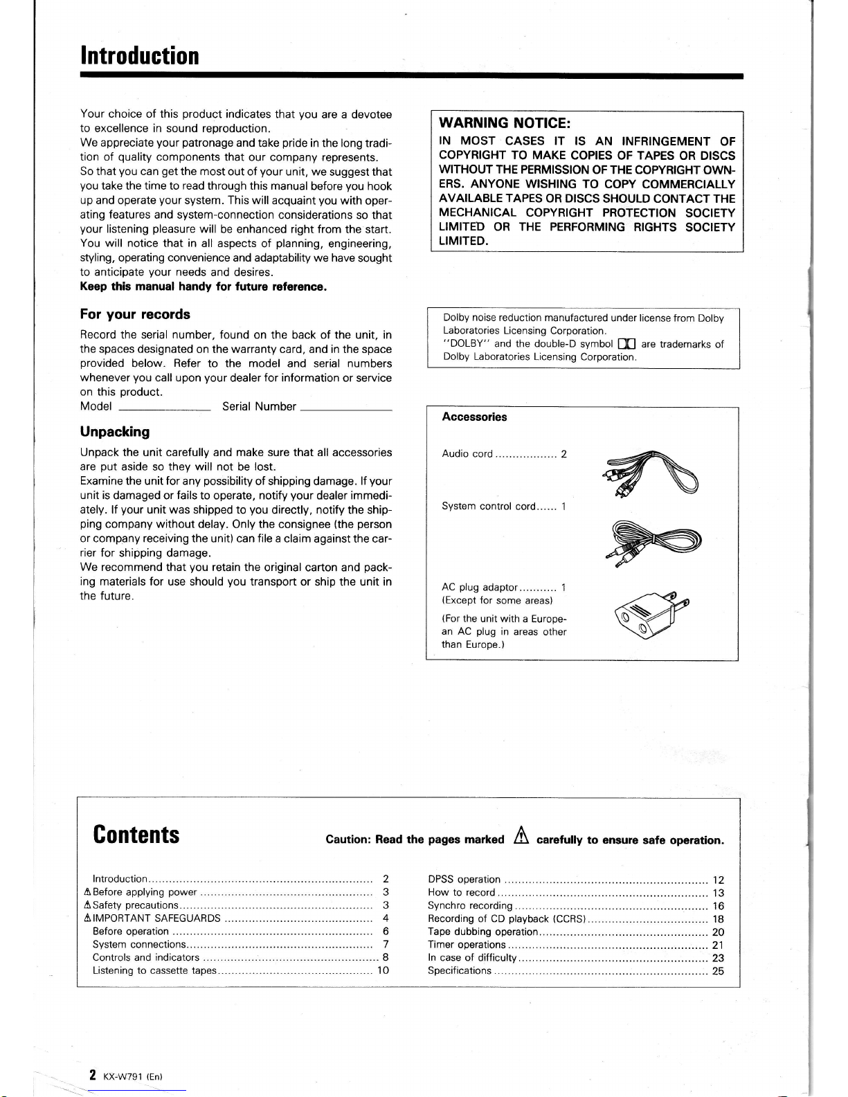
Accessories
Audio
cord ..................
2
System
control
cord...... 1
AC
plug
adaptor...........
1
(Except
for
some areas)
(For
the unit with
a Europe-
an AC
plug
in areas
other
than Europe.)
^
F
Gontents
Caution:
Read
the
pages
markeO
A
carefutty
to
ensure safe
operation.
2 xx-wzsr
trn)
flCaution:
Read
this
page
carefully
to ensure
safe operation.
Before
applying
power
For
the
U.S.A.
and
Ganada
lmportant!
Units shipped
to the
U.S.A. and Canada
are
designed for
opera-
tion on 120 volts
AC
only.
CAUTION:
To
pREVENT
ELEcrRtc
sHocK Do Nor
usE
THE
AC PLUG
WITH AN
EXTENSION
CORD, RECEPTACLE
OR
OTHER
OUTLET
UNLESS THE
BLADES
CAN BE FULLY IN-
SERTED TO
PREVENT
BLADE EXPOSURE.
For
Australia
and Europe
lmportant!
Units shipped
to
Australia
are designed for
operation
on 240
Y
AC
only.
Units shipped
to Europe
are designed for
operation on 230
V
AC
only.
For the
United
Kingdom
lmportant!
Units shipped to the U.K. are designed
for
operation on
240 volts AC
only.
The mains
plug
must
be
removed from the wall
socket
prior
to any internal examination.
The wires in
this
mains lead are coloured in accordance with
the
following
code:
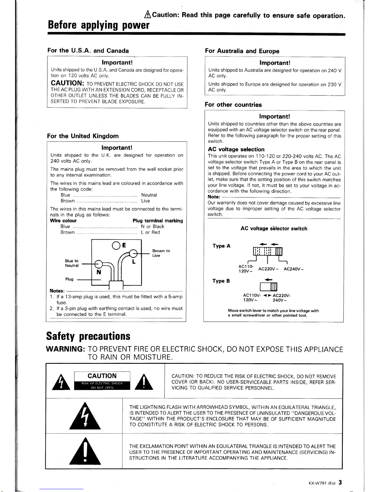
Blue ........... ......... Neutral
Brown......... .........
Live
The wires in this mains lead must be connected to the terminals in
the
plug
as
follows:
Wire colour Plug terminal marking
Brown to
Live
Plug
Notes:
1. lf a 13-amp
plug
is
used, this
must
be
fitted with
a 5-amp
fu se.
2. lf a
3-pin
plug
with earthing contact
is
used,
no
wire must
be connected to
the E terminal.
Blue to
Neutral
For
other countries
lmportant!
Units shipped
to countries
other than the
above countries
are
equipped
with an AC voltage
selector
switch on the rear
panel.
Refer
to the
following
paragraph
for
the
proper
setting
of this
switch.
AC voltage
selection
This
unit operates on 1 10-120
or
220-240
volts AC. The
AC
voltage
selector
switch Type A
or
Type
B on the rear
panel
is
set to the voltage that
prevails
in the
area to which
the unit
is
shipped. Before
connecting the
power
cord
to
your
AC
out-
let,
make sure that
the setting
position
of this
switch matches
your
line
voltage. lf not, it
must
be set to
your
voltage
in ac-
cordance with
the
following
direction.
Note:
Our warranty
does
not
cover damage
caused
by excessive line
voltage due
to
improper
setting
of the AC voltage
selector
switch.
AC voltage
sblector
switch
Type
A
tiJ,l]
Ac22ov- Ac24ov-
Type B
ACl 1
0V
120V
-
Move
switch lever
to match
your
line voltage
with
a small screwdriver
or other
pointed
tool,
m
- <>
AC220V
240V
-
Safety
precautions
WARNING: TO PREVENT FIRE
OR
ELECTRIC
SHOCK, DO NOT
EXPOSE THIS
APPLIANCE
TO RAIN OR MOISTURE.
A
CAUTION
A
CAUTION: TO REDUCE THE
RISK
OF ELECTRIC SHOCK,
DO NOT REMOVE
COVER
(OR
BACK). NO
USER.SERVICEABLE
PARTS INSIDE,
REFER
SER.
VICING
TO OUALIFIED
SERVICE PERSONNEL.
THE LIGHTNING FLASH
WITH
ARROWHEAD
SYMBOL, WITHIN
AN EOUILATERAL TRIANGLE,
IS
INTENDED
TO ALERT THE
USER
TO THE PRESENCE
OF UNINSULATED
"DANGEROUS
VOL-
TAGE" WITHIN THE PRODUCT'S ENCLOSURE THAT
MAY BE
OF SUFFICIENT MAGNITUDE
TO
CONSTITUTE
A RISK
OF ELECTRIC SHOCK TO PERSONS,
THE
EXCLAMATION
POINT WITHIN AN EOUILATERAL TRIANGLE
IS INTENDED TO ALERT THE
USER
TO THE PRESENCE OF IMPOBTANT OPERATING AND MAINTENANCE
(SERVICING)
IN-
STRUCTIONS
IN THE LITERATURE ACCOMPANYING
THE APPLIANCE.
KX-W791 {En) 3
A
Caution : Read
this
IM PORTAIIIT
SAFEGUARDS
Please
read all of the safety and
operating
instructions
before operating this unit.
For
best results, follow
all
warnings
placed
on the unit
and
adhere to the operat-
ing
and use instructions. These safety
and operating
in-
structions should be retained for future reference.
1. Power
sources
-
The unit should be connected
to a
power
supply only of the type described
in
the
operating
instructions
or as
marked
on the appliance.
2. Power-cord
protaction
-
Power-supply cords
should be
routed
so that they are not
likely
to be
walked
on or
pinched
by
items
placed
upon or
against them,
pay particular
attention to cords at
plugs,
convenience receptacles, and the
point
where
they exit
from
the unit.
Never
pull
or stretch
the cord.
3. Grounding
or
polarization
-
The
precautions
should
be
taken
so that the
grounding
or
polariza-
tion
means
of this unit is not defeated.
4. Ventilation
-
The
unit should be situated so that
its location
or
position
does
not interfere with its
proper
ventilation.
To maintain
good
ventilation,
do
not
put
records
or
a
table-cloth
on the unit.
Place the
unit at
least
10
cm away from the walls.
Do
not
use the unit on a bed, sofa,
rug
or similar
surface that
may
block the
ventilation
openings.
5.
Water
and
moisture
-
The unit should not be
used near water
-
for
example,
near
a bathtub,
washbowl,
kitchen
sink,
laundry
tub,
in
a
wet
base-
ment,
or
near
a swimming
pool,
etc.
6. Temperaturo
-
The unit may not function
pro-
perly
if
used at extremely
low,
or
freezing tempera-
tures. The ideal
ambient temperature
is
above
+
5oC
(41'F).
4 rx-wzgt tent
safe
carefully
to
ensure
7. Heat - The
unit
should be situated
away from
heat
sources
such as radiators,
heat registers,
stoves,
or other units
(including
amplifiers)
that
produce
heat.
8. Electric
shock
-
Care should
be taken so that ob-
jects
do
not
fall and liquid is
not spilled into the
en-
closure
through openings. lf
a
metal
object,
such as
a
hair
pin
or a
needle,
comes into
contact with the
inside
of this
unit, a dangerous
electric shock may
result. For families
with
children, never
permit
chil-
dren to
put
anything,
especially metal, inside this
unit.
9.
Enclosure
rsmoval - Never remove
the en-
closure. lf
the
internal
parts
are
touched accidentally,
a serious electric
shock
might
occur.
1O.
Magnetic fields
-
Keep
the unit away from
sources
of
magnetic fields
such
as
TV
sets, speaker
systems, radios, motorized
toys or magnetized
objects.
11. Cleaning
-
Do not
use
volatile
solvents such as
alcohol,
paint
thinner,
gasoline,
or
benzine, etc.
to
clean the
cabinet. Use a clean
dry cloth.
12.
Carts and
stands
-
An
appliance
and cart com-
bination
should
be
moved
with care. Ouick
stops,
excessive force,
and uneven
surfaces may cause the
appliance
and cart combination
to overturn.
l3.Nonuse
periods
-
The
power
cord of the
unit
should be
unplugged from the
outlet
when
left un-
used for
a long
period
of time.
14. Abnormal
smell
-
lf
an abnormal smell
or smoke
is
detected, immediately
turn
the
power
OFF and
pull
out the
power
cord. Contact
your
dealer or
nearest
service
center.
POWER
OFF!
15. Damage
requiring
service
-
The unit should
be
serviced
by
qualified
service
personnel
when:
A. The
power-supply
cord or the
plug
has been
damaged;
or
B. Objects have
fallen,
or
liquid has
been spilled into
the unit;
or
C. The
unit
has
been exposed
to
rain;
or
D. The
unit does not
appear to
operate
normally
or
exhibits
a
marked
change in
performance;
or
E. The
unit
has
been dropped,
or the enclosure
damaged.
16. Servicing
-
The
user should not
attempt to ser-
vice
the unit
beyond that described in the
operating
instructions.
All
other servicing should
be
referred
to
qualified
service
personnel.
17.
Outdoor antenna
grounding
-
lf
an outside an-
tenna is
connected to the
receiver,
be sure the an-
tenna
system
is
grounded
so
as to
provide
some
protection
against
voltage
surges
and built up static
charges. Section
B
1 O
of the
National
Electrical Code,
ANSI/
NFPA No. 70-1984,
provides
information
with
respect
to
proper grounding
of the mast and
supporting structure,
grounding
of the
lead-in wire
to an
antenna discharge unit, size
of
grounding
con-
ACaution
Re-ad
this
p?ge
carefully
sale oDeration-
to
ensure
ductors, location
of antenna-discharge
unit, connec-
tion
to
grounding
electrodes,
and requirements
for
the
grounding
electrode.
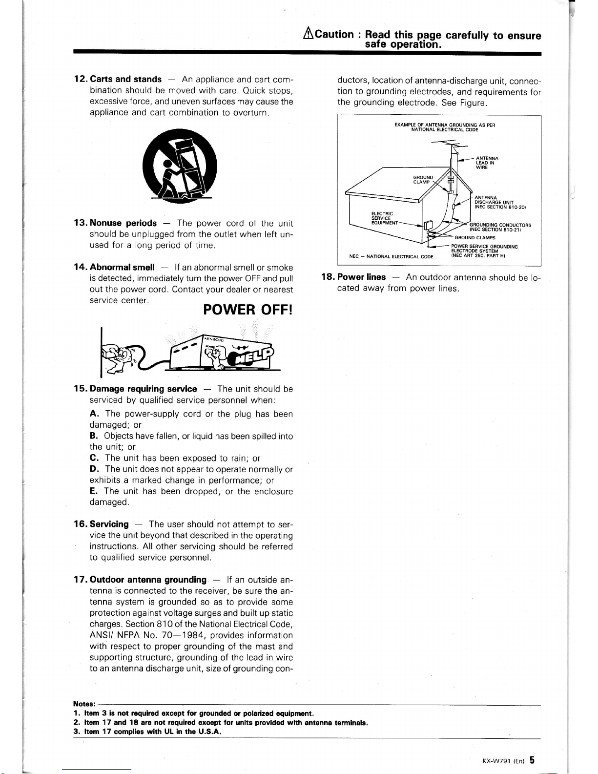
See Figure.
EXAMPLE OF ANTENNA
GROUNDING
AS PER
NATIONAL ELECTRICAL
CODE
ANTENNA
DISCHARGE
UNIT
(NEC
SECTION
81G20t
GBOUNDING
CONDUCTORS
(NEC
SECTTON
810-21)
NEC
-
NATIONAL
ELECTRICAL
CODE
Power
lines
-
An
outdoor
antenna
should
be lo-
cated
away from
power
lines.
18.
Notes:
1. ltgm 3 is not required
except
for
grounded
or
polarized
equipment,
2. ltem 17
and
18
ar6 not
reguired
oxcept tol units
plovidod
with
antonna terminals.
3. ltem 17
complies with UL
in
the U.S.A.
KX-W791
(En)
5
Before
operation
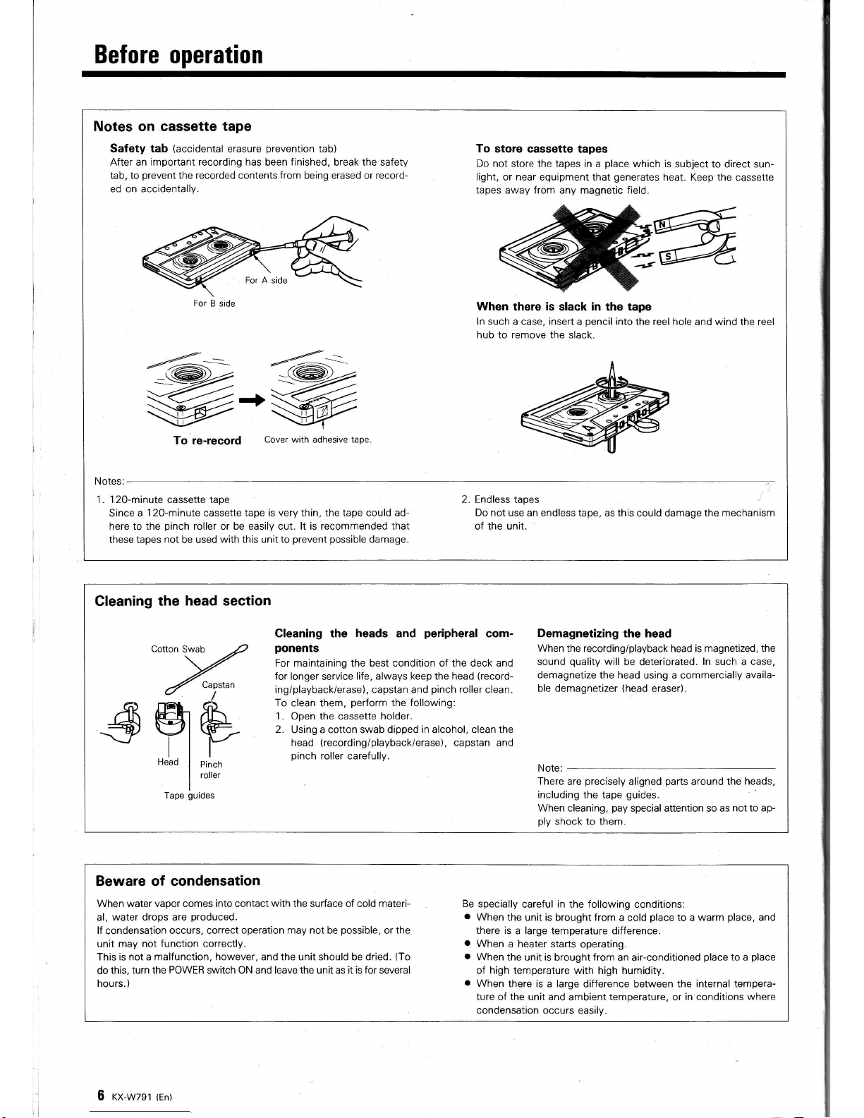
Notes on cassette tape
Safety tab
(accidental
erasure
prevention
tab)
After an important
recording has
been
finished,
break the safety
tab, to
prevent
the recorded contents from being erased or record-
ed on accidentally.
To
store cassette tapes
Do not
store the tapes
in
a
place
which is
subject to direct sun-
light,
or near equipment that
generates
heat. Keep the cassette
tapes away from any magnetic field.
When
there is slack in Sre tape
ln such
a case,
insert
a
pencil
into
the
reel
hole and wind the reel
hub
to
remove
the slack.
TO fe-feCOfd
Cover with
adhesive
tape
Notes:
1 . 12O-minute
cassette
tape
Since a
120-minute
cassette
tape is very thin, the tape could ad-
here to the
pinch
roller or be easily cut. lt is recommended that
these tapes
not
be used
with
this
unit
to
prevent possible
damage.
2. Endless
tapes
Do not use an endless tape,
as
this
could damage the
mechanism
of the unit.
For
B side
Cleaning
the
head section
Cotton
Swab
Tape
guides
Capstan
tr_
Y
Pinch
roller
Gleaning the heads and
peripheral
com- Demagnetizing
the
head
ponents
When
the
recordinglplayback
head is magnetized,
the
For maintaining the best condition of the deck and
sound
quality
will
be deteriorated.
ln such a case,
for
longer
service
life, always keep the head
(record-
demagnetize the
head
using a commercially
availa-
ing/playback/erase), capstan and
pinch
roller
clean.
ble demagnetizer
(head
eraser).
To
clean them,
perform
the
following:
1. Open the cassette
holder.
2. Using a cotton swab dipped
in
alcohol, clean
the
head
(recording/playback/erase),
capstan and
pinch
roller carefully.
Note:
There
are
precisely
aligned
parts
around the
heads,
including the tape
guides.
When
cleaning,
pay
special attention so as
not to ap-
ply
shock to them.
Beware of condensation
When water vapor comes into contact
with
the surface of cold materi- Be
specially
careful
in
the following conditions:
al,
water drops are
produced.
.
When
the unit is
brought
from
a cold
place
to a
warm
place,
and
lf
condensation
occurs, correct operation
may not
be
possible,
or
the
there is
a large temperature difference.
unit
may not function correctly.
.
When
a heater
starts operating.
Thisisnotamalfunction,however,andtheunitshouldbedried.(To
o
Whentheunitisbroughtfromanair-conditionedplacetoaplace
do this,
turn the POWER switch ON and leave the unit as it is
for
several
of
high
temperature with high humidity.
hours.)
o
When
there is a large
difference between the
internal tempera-
ture of the unit
and ambient
temperature,
or
in conditions
where
condensation
occurs easily.
6 rx-wzst
tent
System
Gonnections
Make
connection
as shown below. When
connecting
the related
system components,
refer
also to
the instruction
manuals
of the related
components.
Do
not
plug
in
the
power
lead until
all connections
are completed.
AC voltage
selector
switch
(Except
for
some
areas)
control
cord
\H;;t[J:"*;fi#;r
//dtb@@a'l
//obdtood
\+
To
AC
outlet
Amprifier
or Receiver
o
o
D
@E
o
@
EO
ErEr
-r
O
Turntable
=re
CD
player
:=
ll-ei-Ll
System
control
connection
When
connected to an
amplifier or
receiver
having KENWOOD
SYSTEM
CONTROL terminals,
system operation such as remote con-
trol is made
possible.
For
details,
refer
to the instruction manual of
the
amplifier
or
receiver.
ln addition, when
system control cords are
also
connected to
the CD
player
or
turntable,
other functions such
as
synchro recording
(see
page
1 6) and CCRS recording
(see
page
18) become
possible.
lf
your
amplifier or receiver
is not equipped
with the SYSTEM
CONTROL
terminals,
do not
connect anything to any
SYSTEM
CONTROL
terminal.
Do not
connect the
unit in any
system configuration
other
than
specified.
.
Be sure to insert the
system control cord
plugs
fully into the
SYSTEM CONTROL terminals.
a
lf the system
control cord and audio cords are not connected
properly,
the automatic
system
governing
remote control and sys-
tem functions will
not operate.
x
@
o
@
Notes:
1 .
Connect all cords firmly.
lf connections are loose there
could be
loss of sound
or
noise
produced.
2. When
plugging
and
unplugging connection
cords, be sure to
first
remove the
power
cord from the AC
outlet. Plugging/unplugging
connection
cords without removal
of the
power
cord can cause
malfunctions
or damage
to the unit.
KX-W791
(En)
7
r
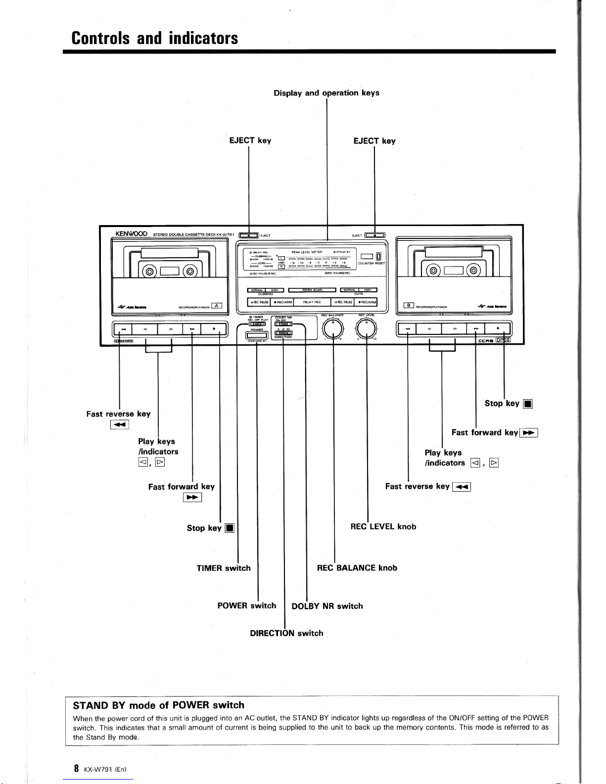
Gontrols and indicators
Display and operation
keys
DIRECTION switch
Fast reverse
key
E
Play
Stop"key
I
Fast forward keyb>l
/indicators
tr.tr
Play keys
/indicators
tr,
tr
Fast
forward
key
E
Fast
reverse key
f<<l
Stop
key
D
REG LEVEL knob
TIMER switch
REC BALANCE knob
POWER switch
DOLBY
NR
switch
STAND
BY mode of
POWER switch
When the
power
cord o{
this unit
is
plugged
into an
AC
outlet,
the
STAND
BY indicator lights up regardless
of
the
ONiOFF
setting of the
POWER
switch.
This indicates
that a small
amount of current
is being supplied to the unit to back up the memory contents. This mode
is referred to as
the Stand
By
mode.
I
rx-wzgt
{en)
 Loading...