

Kenwood KXF-W4030, CT-405 User Manual

STEREO CASSETTE TAPE DECK
KXF-W4030
CT-405
INSTRUCTION MANUAL
KENWOOD CORPORATION
B60-4536-08 (EN)
Introduction
2
Before applying power
Units are designed for operation as follows.
U.S.A. and Canada ............................ AC 120 V only
Australia.......................................... AC 240 V only
Europe and U.K. ............................... AC 230 V only
*Other countriesAC 110-120 / 220-240 V switchable
For the United Kingdom
Factory fitted moulded mains plug
1. The mains plug contains a fuse. For replacement, use only a 13-Amp
ASTA-approved (BS1362) fuse.
2. The fuse cover must be refitted when replacing the fuse in the
moulded plug.
3. Do not cut off the mains plug from this equipment. If the plug fitted
is not suitable for the power points in your home or the cable is too
short to reach a power point, then obtain an appropriate safety
approved extension lead or adapter, or consult your dealer.
If nonetheless the mains plug is cut off, remove the fuse and
dispose of the plug immediately, to avoid a possible shock hazard by
inadvertent connection to the mains supply.
IMPORTANT
The wires in the mains lead are coloured in accordance with the
following code:
Blue : Neutral
Brown : Live
Do not connect those leads to the earth terminal of a three-pin plug.
Caution: Read this section carefully to ensure safe operation.
ENERGY STAR
As an
tion has determined that this products meets the
ENERGY STAR
This product can save energy. Saving energy reduces air pollution and
lowers utility bills.
®
Partner, Kenwood Corpora-
®
guidelines for energy efficiency.
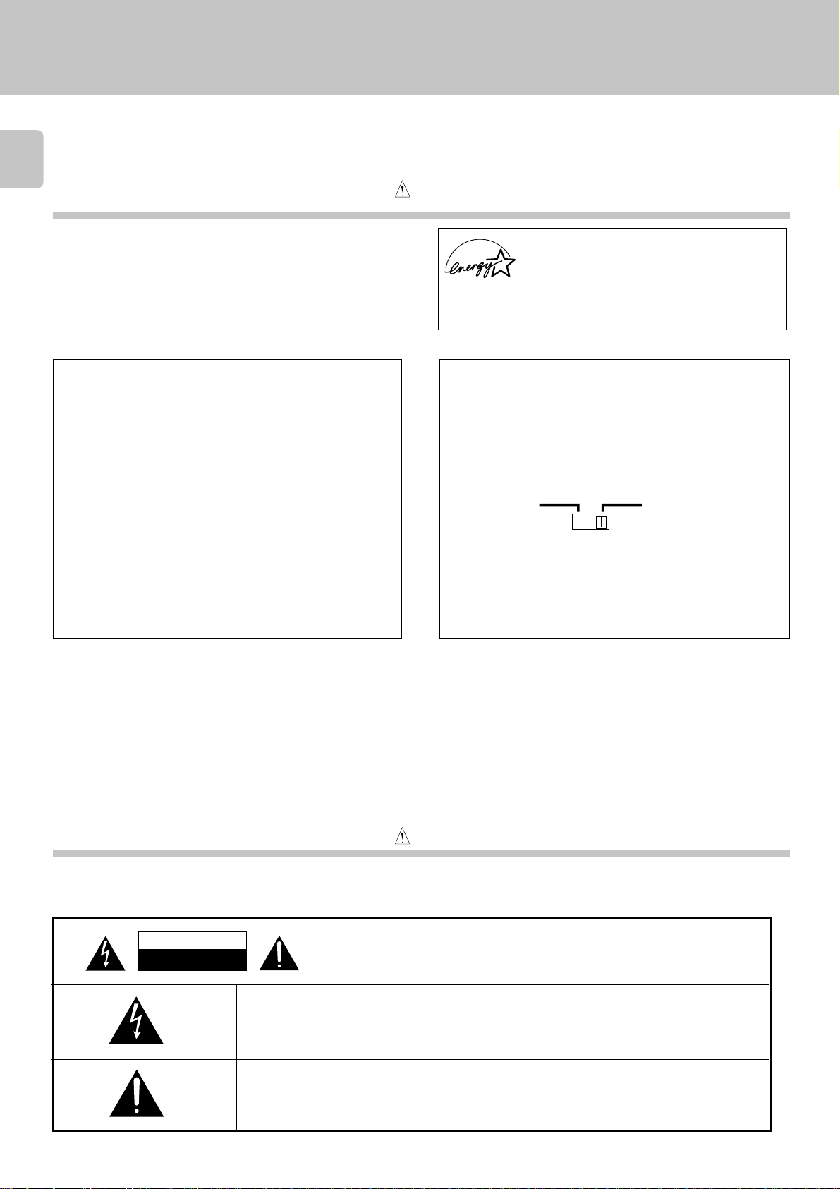
*AC voltage selection
The AC voltage selector switch on the rear panel is set to the
voltage that prevails in the area to which the unit is shipped.
Before connecting the power cord to your AC outlet, make
sure that the setting position of this switch matches your line
voltage. If not, it must be set to your voltage in accordance
with the following direction.
AC voltage selector switch
AC110120V~
Move switch lever to match your line voltage with
a small screwdriver or other pointed tool.
Note:
Our warranty does not cover damage caused by excessive
line voltage due to improper setting of the AC voltage selector switch.
AC220240V~
Safety precautions
Caution: Read this section carefully to ensure safe operation.
WARNING: TO PREVENT FIRE OR ELECTRIC SHOCK, DO NOT EXPOSE
THIS APPLIANCE TO RAIN OR MOISTURE.
CAUTION
RISK OF ELECTRIC SHOCK
DO NOT OPEN
THE LIGHTNING FLASH WITH ARROWHEAD SYMBOL, WITHIN AN EQUILATERAL
TRIANGLE, IS INTENDED TO ALERT THE USER TO THE PRESENCE OF UNINSULATED
“DANGEROUS VOL-TAGE” WITHIN THE PRODUCT’S ENCLOSURE THAT MAY BE OF
SUFFICIENT MAGNITUDE TO CONSTITUTE A RISK OF ELECTRIC SHOCK TO PERSONS.
THE EXCLAMATION POINT WITHIN AN EQUILATERAL TRIANGLE IS INTENDED TO
ALERT THE USER TO THE PRESENCE OF IMPORTANT OPERATING AND MAINTENANCE (SERVICING) INSTRUCTIONS IN THE LITERATURE ACCOMPANYING THE
APPLIANCE.
CAUTION: TO REDUCE THE RISK OF ELECTRIC SHOCK, DO NOT
REMOVE COVER (OR BACK). NO USER-SERVICEABLE PARTS INSIDE, REFER SERVICING TO QUALIFIED SERVICE PERSONNEL.
Special features
Dolby HX pro and Auto-Bias function
DPSS function
CCRS function
Dubbing function
The Dolby HX pro headroom extension and auto-bias function provide a recording with
superior high-frequency characterisitics.
¶Simple operations allow you to use the following convenient functions.
1 Skip Play 2 Single-tune repeated playback
(DPSS: Direct program Search System)
¶This function automatically stes the optimum recording level of the disc to be recorded,
making it easy to record a CD.
(CCRS: Computer-Controlled CD Recording System)
¶ With an easy operation, the tape loaded in deck A can be dubbed onto the tape in deck B.
making it easy to record a CD.
Unpacking
Unpack the unit carefully and make sure that all accessories are put aside so they will not be lost.
Examine the unit for any possibility of shipping damage. If your unit is damaged or fails to operate, notify your dealer immediately. If your unit was shipped
to you directly, notify the shipping company without delay. Only the consignee (the person or company receiving the unit) can file a claim against the carrier
for shipping damage.
We recommend that you retain the original carton and packing materials for use should you transport or ship the unit in the future.
Keep this manual handy for future reference.
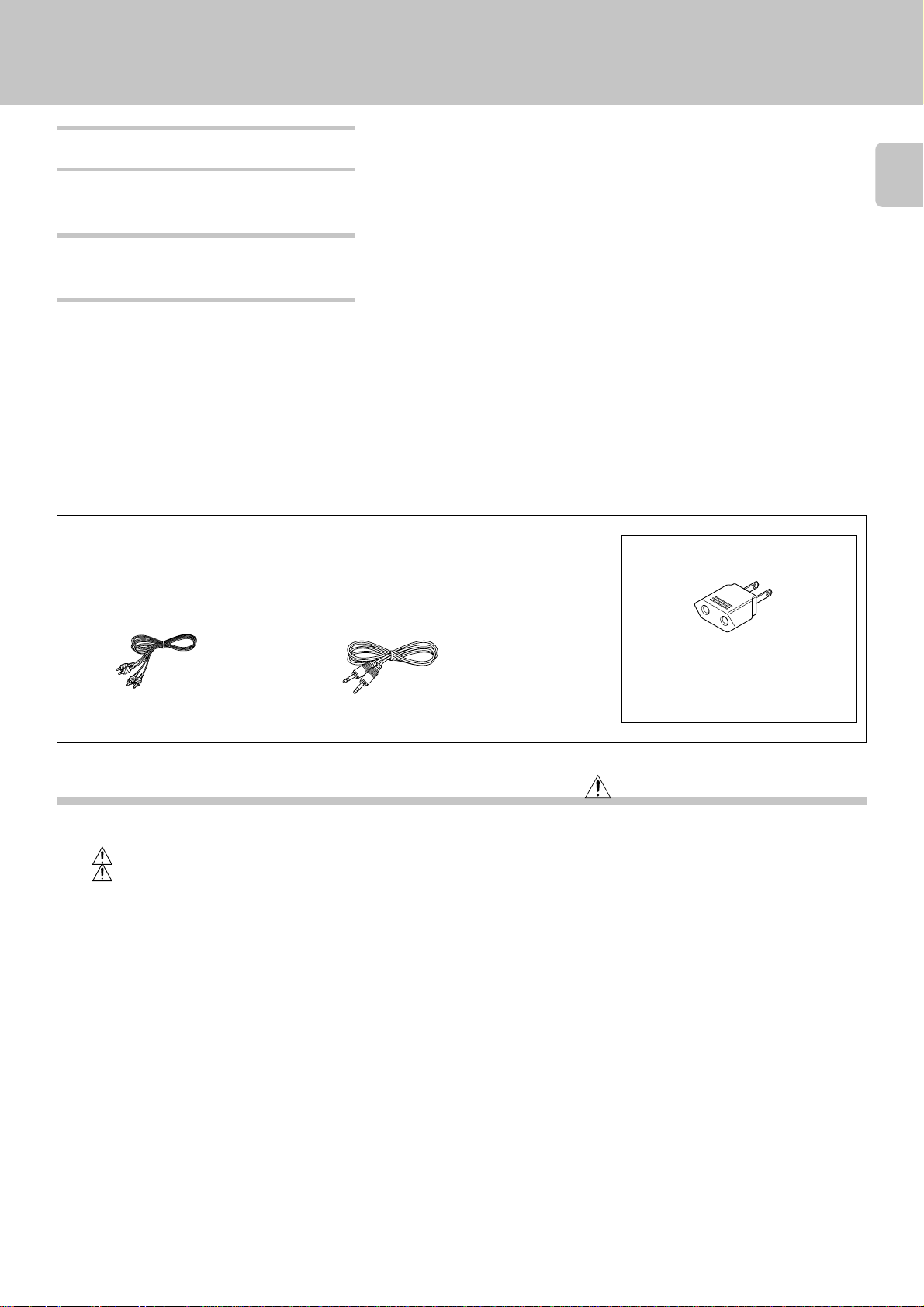
Accessories
Check that the following accessories are present.
AC plug adaptor .............. (1)
3
Audio cord ........................ (2) System control cord ............ (1)
Contents
Introduction.................................................................. 2
Before applying power ....................................................... 2
Safety precautions .............................................................. 2
Special features ................................................................... 3
Important items ........................................................... 4
Maintenance ........................................................................ 4
Reference ............................................................................. 4
System connections .................................................... 6
Controls and indicators ............................................... 8
Preparation for playback (recording) ....................... 10
Playback (recording) preparation .................................... 10
Listening to cassette tapes ....................................... 11
Normal playback ............................................................... 11
Relay playback ...................................................................12
Convenient music search (DPSS) ............................. 14
Skip play operation ........................................................... 14
Single-tune repeated playback operation ....................... 15
Caution: Read the pages marked carefully to ensure safe operation.
Use to adapt the plug on the power cord
to the shape of the wall outlet.
(Accessory only for regions where use is
necessary.)
How to record (Deck B only)..................................... 16
Normal recording .............................................................. 16
Tape dubbing operation (Deck A \ Deck B) ........... 19
Tape dubbing ..................................................................... 19
Convenient CD recording (Deck B only) .................. 20
CD synchro recording ....................................................... 20
Recording of CD playback (CCRS)(Deck B only) ............. 21
Timer operations........................................................ 22
Timer playback of tape...................................................... 22
Timer recording of tuner broadcast(Deck B only) .......... 23
In case of difficulty..................................................... 24
Glossary ...................................................................... 26
Specifications ............................................................. 27

Important items
Maintenance
4
Cleaning
Unplug this appliance from the wall outlet before cleaning. Do not
use volatile solvents such as alcohol, paint thinner, gasoline, or
benzine, etc. to clean the cabinet. Use a clean dry cloth.
Cleaning the head section
Cleaning the heads and peripheral com-
Cotton swab
Head
Tape guides
Capstan
Pinch roller
ponents
For maintaining the best condition of the deck and
for longer service life, always keep the head (recording/playback/erase), capstan and pinch roller clean.
To clean them, perform the following:
1. Open the cassette holder.
2. Using a cotton swab dipped in alcohol, clean the
head (recording/playback/erase), capstan and
pinch roller carefully.
Caution against contact revitalizer
Do not use contact cleaners because it could cause a malfunction.
Be specially careful against contact cleaners containing oil, for they
may deform the plastic componente.
Demagnetizing the head
When the recording/playback head is magnetized,
the sound quality will be deteriorated. In such a
case, demagnetize the head using a commercially
available demagnetizer (head eraser).
There are precisely aligned parts around
Note
NoteNote
the heads, including the tape guides.
When cleaning, pay special attention so
as not to apply shock to them.
Reference
Caution on condensation
Condensation (of dew) may occur inside the unit when there is a great
difference in temperature between this unit and the outside.
This unit may not function properly if condensation occurs. In this
case, leave the unit for a few hours with the power left ON, and restart
the operation after the condensation has dried up.
Be specially cautions against condensation in a following circumstance:
When this unit is carried from a place to another across a large
difference in temperature, when the humidity in the room where this
unit in installed increases, etc.
Dolby noise reduction and HX Pro headroom extension manufactured under license from Dolby Laboratories Licensing Corporation.
HX Pro originated by Bang & Olufsen.
“DOLBY”, the double-D symbol and “HX PRO” are trademarks of
Dolby Laboratories Licensing Corporation.
WARNING NOTICE:
IN MOST CASES IT IS AN INFRINGMENT OF COPYRIGHT
TO MAKE COPIES OF TAPES OR DISCS WITHOUT THE
PERMISSION OF THE COPYRIGHT OWNERS. ANYONE
WISHING TO COPY COMMERCIALLY AVAILABLE TAPES
OR DISCS SHOULD CONTACT THE MECHANICAL COPYRIGHT PROTECTION SOCIETY LIMITED OR THE PERFORMING RIGHTS SOCIETY LIMITED.
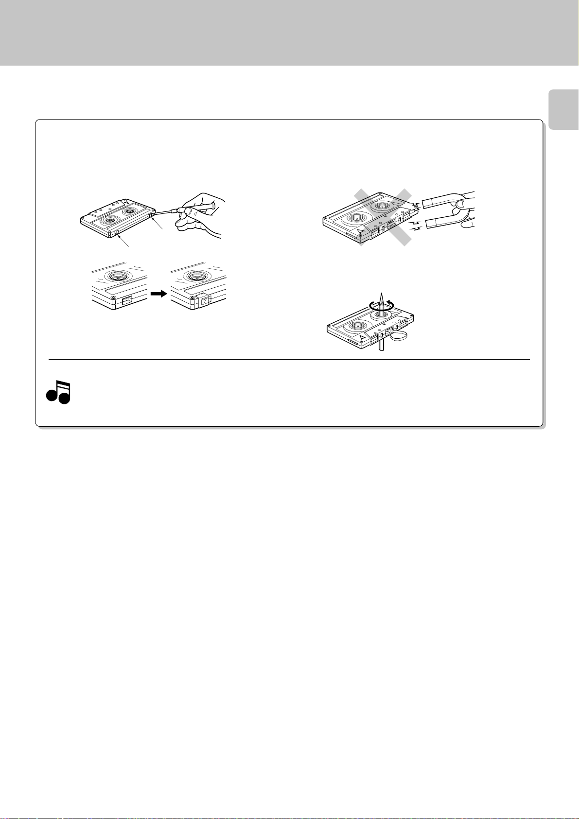
Handling the cassette tape
Notes on cassette tape
Safety tab (accidental erasure prevention tab)
After an important recording has been finished, break the safety
tab, to prevent the recorded contents from being erased or
recorded on accidentally.
For A side
For B side
Important items
5
To store cassette tapes
Do not store the tapes in a place which is subject to direct
sunlight, or near equipment that generates heat. Keep the
cassette tapes away from any magnetic field.
N
S
When there is slack in the tape
In such a case, insert a pencil into the reel hole and wind the reel
hub to remove the slack.
To re-record
1. Longer tape than 110 minutes cassette tape
Since longer tape than 110 minutes cassette tape is very
NotesNotes
Notes
thin, the tape could adhere to the pinch roller or be easily cut.
It is recommended that these tapes not be used with this
unit to prevent possible damage.
Apply tape only to the position
where the tab has been removed.
2. Endless tapes
Do not use an endless tape, as this could damage the mechanism
of the unit.
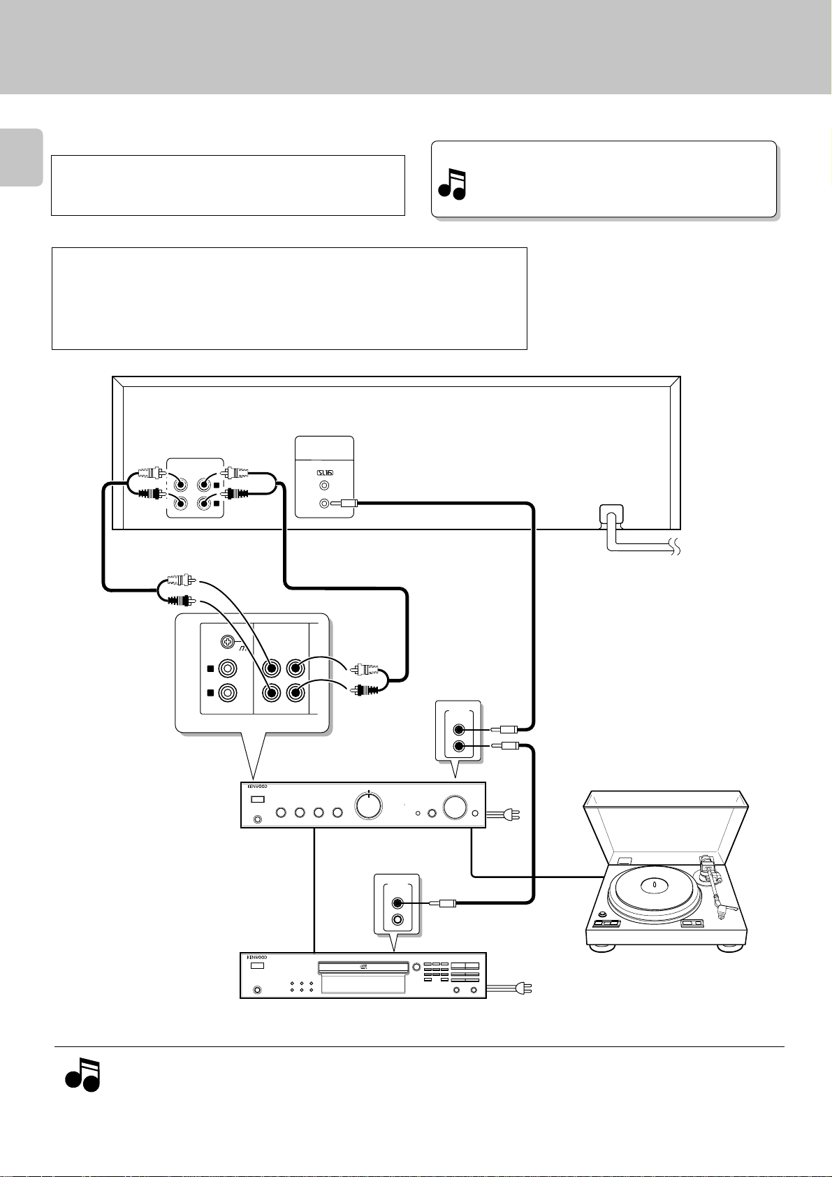
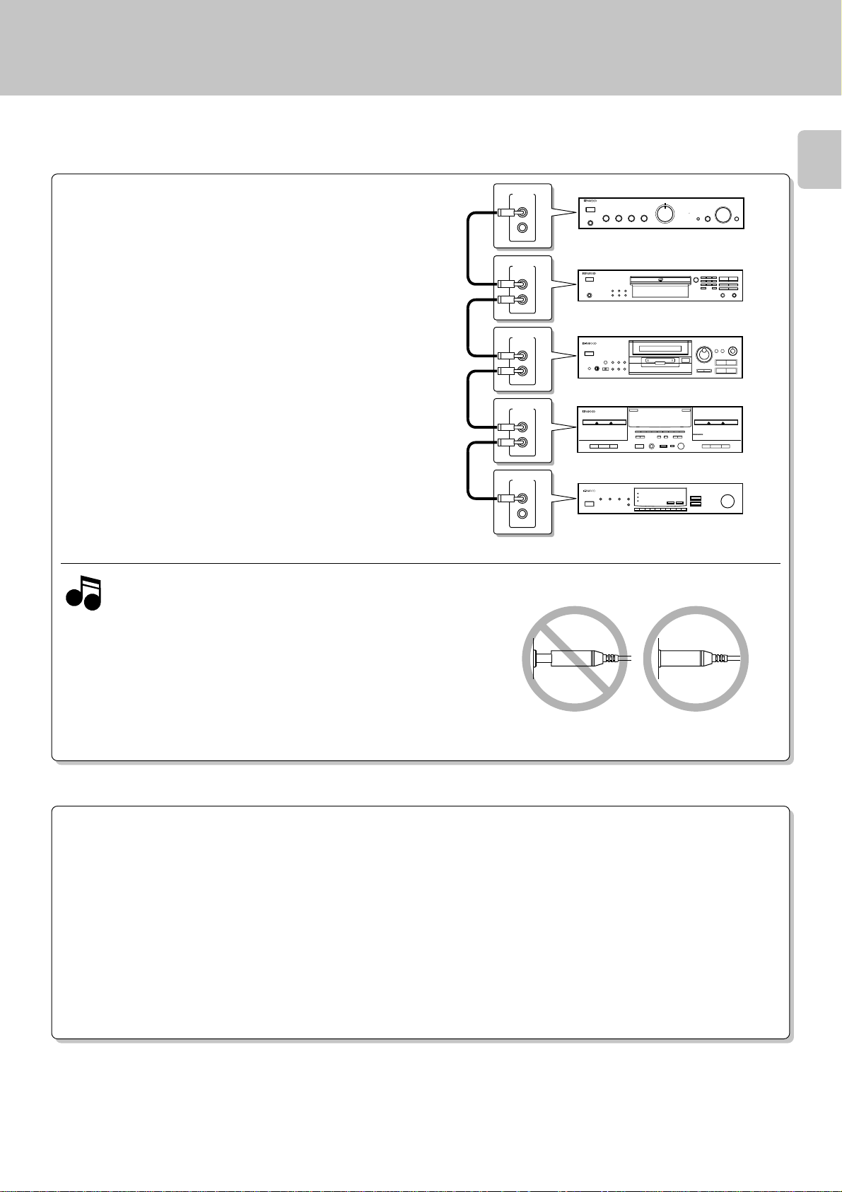
System connections
Make connections as shown below.
When connecting the related system components, refer also to the
instruction manuals of the related components.
6
Caution:
Do not plug in the power lead until all connections are completed.
( Except for U.S.A., Canada )
Caution
Be sure to adhere followings. Or proper ventilation will be blocked causing damage or fire hazard.
÷ Do not place any objects impairing heat radiation onto the top of unit.
÷ Leave a space around the unit (from the largest outside dimension including projection)
equal or greater than, shown below.
Top panel : 50 cm Side panel : 10 cm Back panel : 10 cm
Malfunction of microcomputer
If operation is not possible or erroneous display appears even
though all connections have been made properly, reset the
microcomputer referring to “In case of difficulty”.
¢
REC PLAY
LINE IN
LINE OUT
L
R
L
R
Audio cords
SIGNAL
GND
PHONO
L
R
Amplifier or
Receiver
*The connected component model is
variable dependent on areas.
TAPE
REC PLAY
Audio cord
SYSTEM CONTROL
Audio cords
SL-16
SYSTEM
CONTROL
System control cord
SYSTEM
CONTROL
System control cord
TO AC outlet
Turntable
Notes
Notes
123
76
456
0
789
4¢
0 +10
1¡
CD player
1. Connect all cords firmly. If connections are loose, there could be loss of sound or noise produced.
2. When plugging and unplugging connection cords, be sure to first remove the power cord from the AC outlet. Plugging/unplugging
connection cords without removal of the power cord can cause malfunctions or damage to the unit.
SYSTEM CONTROL CONNECTIONS
Connecting system control cords after connecting a KENWOOD
audio component system lets you take advantage of convenient
system control operations.
This unit is compatible only with the [SL16] mode. The system control operation is not available if the unit is connected in the [XS-8]
connection mode.
SYSTEM
CONTROL
SYSTEM
CONTROL
SYSTEM
CONTROL
SYSTEM
CONTROL
SYSTEM
CONTROL
System connections
7
0
237
0
TAPE B
CCRS
237
÷Do this operation after completing all connections.
(Ensure that the unit is set to POWER OFF.)
1. If your amplifier or receiver does not have a system control terminal,
Notes
Notes
do not connect any system control cords to the system control terminals on the other components.
2. Do not connect system control cords to any components other than
those specified by Kenwood. It may cause a malfunction and damage
your equipment.
3. Be sure the system control plugs are inserted all the way in to the
system control terminals.
SYSTEM CONTROL OPERATIONS
Remote Control
Lets you operate this unit with the system remote control unit supplied with the amplifier or receiver.
Automatic Operation
Automatically switches the input selector on the amplifier or receiver when you start playback from this unit.
Synchronized Recording
Lets you synchronize recording with the start of playback when recording from CD.
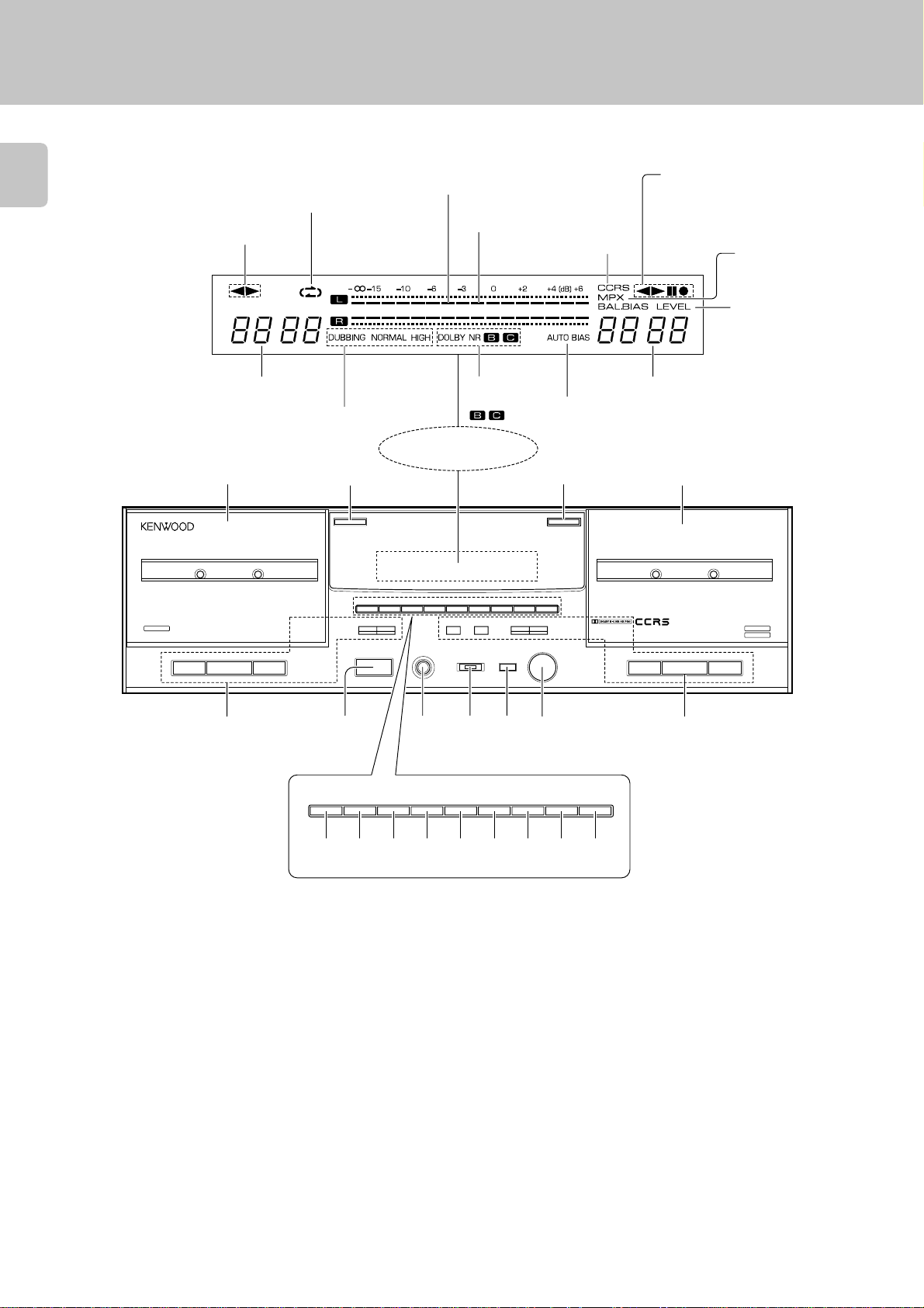
Controls and indicators
8
REV.MODE indicators
Operation indicators (Deck A)
2, 3 Transport␣ direction
indicators
Peak level indicators
(Dolby NR reference level)
CCRS indicator
Operation indicators (Deck B)
2, 3 Transport␣ direction
indicators
¶ Recording indicator
8 Pause indicator
MPX FILTER indicator
BAL. BIAS LEVEL indicators
TAPE A
PLAYBACK
Deck A COUNTER
indicators
DUBBING indicators
NORMAL
HIGH
DOLBY NR
indicators
AUTO BIAS
indicator
Deck B COUNTER
indicators
Display
12 34
AUTO REVERSE
237
0
RESET A
DOLBY NR REV.MODE NORM.DUBB HIGH DUBB MPX FILTER
1
¡ 1 ¡8PAUSE 
POWER
- ON – OFF
RESET A
DOLBY NR REV.MODE NORM.DUBB HIGH DUBB MPX FILTER
PHONES
REC/ARM
TIMER PLAY
REC OFF PLAY
CCRS AUTO BIAS RESET B
MODE
0
REC LEVEL/BAL
/BIAS
MIN/L MAX/R
CCRS AUTO BIAS RESET B
AUTO REVERSE
!098765
TAPE B
RECORDING
PLAYBACK
237
@#$%^&*()

Controls and indicators
1 Deck A
This deck is used exclusively for playback.
2 Deck A eject (0) key 0
Press to open the cassette holder of
deck A.
3 Deck B eject (0) key 0
Press to open the cassette holder of
deck B.
4 Deck B
This deck is capable of both playback
and recording.
5 Deck A operation keys 0~!
1 :Rewind key (for fast winding of
tape toward the left reel seen
from you)
¡ :Fast Forward key (for fast wind-
ing of tape toward the right reel
seen from you)
2, 3 : Play keys
7 : Stop key (Stop)
6 POWER switch 0
Press to turn this unit ON and OFF.
7 PHONES jack !
Connect stereo headphones (optional)
here.
8 TIMER switch ™
This switch is used in setting of timer
playback and timer recording.
9 MODE key ^
Press to change the recording
level,balance,or bias settings.
0 REC LEVEL/BAL/BIAS knob ^
Adjust this before recording.
! Deck B operation keys
2, 3 : Play keys
7 : Stop key (Stop)
1 :Rewind key (for fast winding of
tape toward the left reel seen
from you)
¡ :Fast Forward key (for fast wind-
ing of tape toward the right reel
seen from you)
pause (
record (
@ RESET A key !
Press to reset the tape counter of deck
A to “0000”.
# DOLBY NR key 0
Press to switch the Dolby Noise Reduction mode to B = C = OFF. This makes
it possible to use the Dolby NR effect in
recording and playback.
$ REV. MODE key 0
Press to change the tape transport direction.
% NORM.DUBB. key (
Dubbing at the normal speed.
^ HIGH DUBB. key (
Dubbing at a high speed.
8PAUSE) key !
:Press to let tape transport pause
temporarily.
¶REC/ARM) key ^
:Press in stop mode to start recording or press in record mode
to let the recording pause after
leaving a non-recorded blank of
4 seconds.
& MPX FILTER key &
9
Press to reduce beat noise when recording FM broadcasts.
* CCRS key ¡
Press to start recording after automatic
setting of the optimum CD recording
level and optimum tape recording bias.
( AUTO BIAS key ^
When this key is pressed, the bias level
appropriate for the tape is set automatically for recording.
) RESET B key
Press to reset the tape counter of deck
B to “0000”.
 Loading...