

Kenwood VR-507, KRFW7050D, KRF-V7050D Instruction Manual
KENWOOD
AUDIO VIDEO SURROUND RECEIVER
VR-507
KRFW7050D
INSTRUCTION MANUAL
KENWOOD CORPORATlON
This mstrudion manual IS used to describe multiple models listed above.
Model availability and features (functions) may differ depending on the country and
sales area.
About the supplied rem&e control
Compared to standard remote controls, the remote control supplied with this receiver has several operation
modes. These modes enable the remote control to control other audio/video components. In order to
effectively use the remote control it IS Important to read the operating instructions and obtain a proper
understanding of the remote control and how to switch its operation modes (etc.).
Using the remote control without completely understanding its design and how to switch the operation modes
may result in Incorrect operations.
B60-5027-00 00 a (K, P, Y, M, X, I) r%-; 0009
Units are deslgned for operation as follows.
U.S.A. and Canada.. ......................................... AC 120 V only
Australia ........................................................... AC 240 V only
Europe and U.K.. .............................................. AC 230 V only
Chma and Russia ............................................ AC 220 V only
Other countries . . . . . . . . . . . . AC 110-120 1220-240 V switchable*
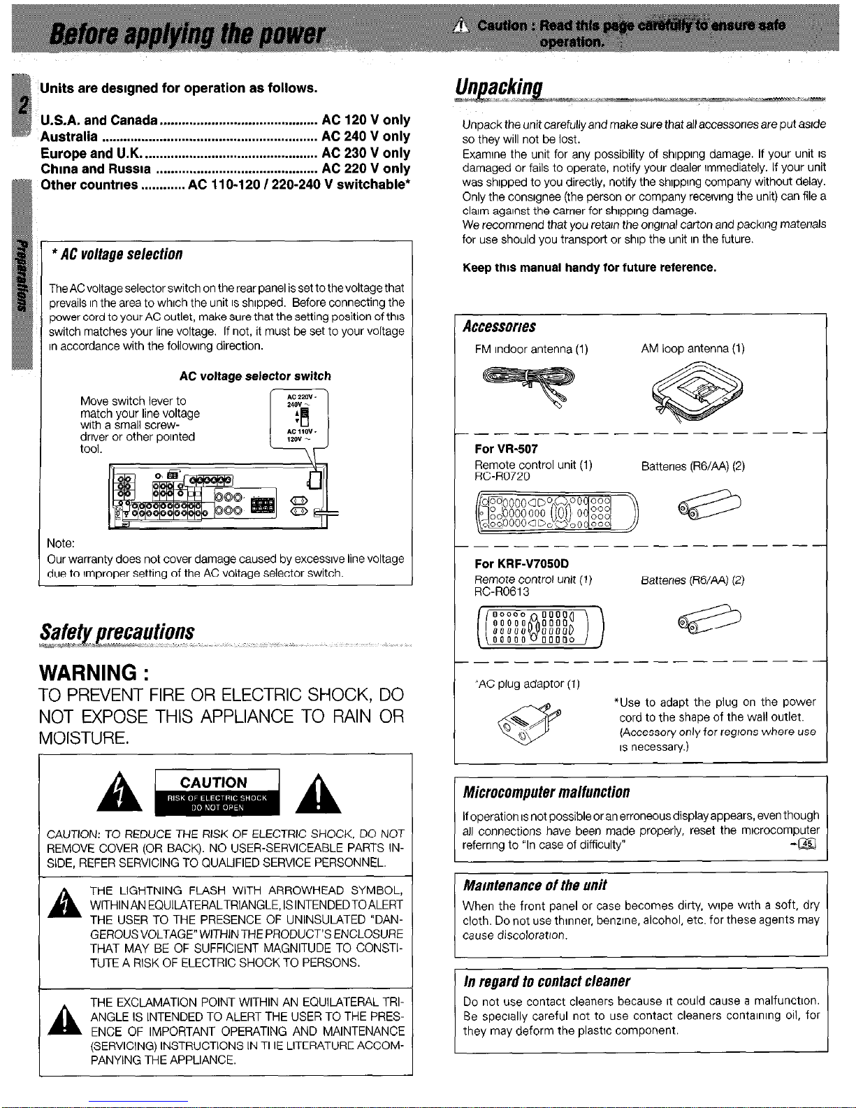
* AC voltage selection
The AC voltage selector switch on the rear panel is set to the voltage that
prevails In the area to which the unit IS shipped. Before connecting the
power cord to your AC outlet, make sure that the setting position of this
switch matches your line voltage. If not, it must be set to your voltage
n accordance with the followlng direction.
AC voltage selector switch
Move switch lever to
match your line voltage
with a small screwdriver or other polnted
tool.
rlote:
Iur warranty does not cover damage caused by excessive line voltage
lue to Improper setting of the AC voltage selector switch.
TO PREVENT FIRE OR ELECTRIC SHOCK, DO
NOT EXPOSE THIS APPLIANCE TO RAIN OR
MOISTURE.
CAUTION: TO REDUCE THE RISK OF ELECTRIC SHOCK, DO NOT
REMOVE COVER (OR BACK). NO USER-SERVICEABLE PARTS INSIDE, REFER SERVICING TO QUALIFIED SERVICE PERSONNEL.
A
THE LIGHTNING FLASH WITH ARROWHEAD SYMBOL,
WITHIN AN EQUILATERALTRIANGLE, ISINTENDEDTOALERT
THE USER TO THE PRESENCE OF UNINSULATED “DANGEROUS VOLTAGE” WITHIN THE PRODUCT’S ENCLOSURE
THAT MAY BE OF SUFFICIENT MAGNITUDE TO CONSTITUTE A RISK OF ELECTRIC SHOCK TO PERSONS.
AL
THE EXCLAMATION POINT WITHIN AN EQUILATERAL TRIANGLE IS INTENDED TO ALERT THE USER TO THE PRES-
ENCE OF IMPORTANT OPERATING AND MAINTENANCE
(SERVICING) INSTRUCTIONS IN THE LITERATURE ACCOM-
PANYING THE APPLIANCE.
Unpack the unit carefully and make sure that all accessones are put aslde
so they will not be lost.
Examine the unit for any possibility of shlpplng damage. If your unit IS
damaged or fails to operate, notify your dealer Immediately. If your unit
was shipped to you directly, notify the shIppIng company without delay.
Only the consignee (the person or company receiving the unit) can file a
claim against the carrier for shipping damage.
We recommend that you retatn the ongtnal carton and packing materials
for use should you transport or ship the unit In the future
Keep this manual handy for future reference.
Accessories
FM Indoor antenna (1) AM loop antenna (1)
- ______ -_----------
For Wt.507
Remote control unit (1)
RC-R0720
Batteries (RG/AA) (2)
---_---------------
For KRF47050D
Remote control unit (1)
RC-ROGI 3
Batteries (RG/AA) (2)
-______-_--------
--
‘AC plug adaptor (1)
*Use to adapt the plug on the power
cord to the shape of the wall outlet.
(Accessory only for regions where use
IS necessary.)
Microcomputer malfunction
If operation IS not possible or an erroneous display appears, even though
all connections have been made properly, reset the mlcrocomputer
refernng to “In case of difficulty”
-aI
Maintenance of the unit
When the front panel or case becomes dirty, wipe with a soft, dry
cloth. Do not use thinner, benzene, alcohol, etc. for these agents may
cause discoloration.
Do not use contact cleaners because It could cause a malfunction.
Be specially careful not to use contact cleaners contalnlng 011, for
they may deform the plastic component.
a Before applying the power
................... 2
a Safety precautions ..............................................
2
Unpackrng
.......................................................... 2
How to use thus manual
...................................... 4
Specral features ..................................................
5
Names and functions of parts ................
6
Remote control unit (RCR0720) (W-507). ......... 7
Remote control unit (RCRO613) (KRF-V7050D) .8
Settin up the system
............. . ..
. . . ...... 9
Connecting audio components ......................... 10
Connecting vrdeo components ......................... 1 1
Connecting a DVD player (6-channel Input) ...... 12
Digital connections ........................................... 13
I’ Connecting to the AV AUX jacks ...................... 14
Connecting the antennas .................................. 14
Connecting the system control ......................... 15
Connecting the speakers .................................. 16
Connecting the termrnals .................................. 17
Preparing the remote control ............................ 18
Preparm for surround sound.. ............. 19
Normal playback .............................
.20
Preparing for playback.. ....................................
20
Lrstenrng to a source component
.................... .21
Adjusting the sound ..........................................
21
Recording .....................................
.22
Recording audio (analog sources)
.................... 22
Recording vrdeo ................................................ 23
Recording audio (digital sources) ...................... 23
Listen/n9 to radio broadcasts
.............. .23
Tunrng radio stations
........................................ 23
Presetting radio stations manually .................... 24
Recerving preset stations ..................................
24
Recervrng preset stations In order (PCALL).
....
.24
Ambience effects.. ........................... .25
Surround modes ............................................... 25
Surround play ................................................... 27
DVD 6-channel playback
.................................. 28
Convenient functions
........................................ 28
ftasrc remote control operations for other
components .................................... 31
Regrstenng setup codes for other
components (RCR0720) ..................................
31
Programming TV/VCR combo control
.............. 31
Searchrng for your code ...................................
32
Checkrng the codes.. ........................................
32
Re-assrgnrng device keys ................................. 32
Changrng volume lock ...................................... 33
Operating other components.. .......................... 33
Regrstenng setup codes for other
components (RC-RO613) .................................. 34
Operating other components (RC-R0613)
.......
.34
Setup code chart (for VR-507 (RC-R0720))
..... (35
Setup code chart (for KRF-V7050D
(RGR0613)).
..................................................... 39
CASSETTE deck, CD player & MD recorder
operations..
....................................................... 40
Other components’ operations
......................... 42
In case of difficulty ..........................
,45
i& Specifications ................................
-47
nrthnI/S
A
Y, .,,Y “.“.“.
FCC WARNING
This equipment may generate or use radio frequency energy. Changes
or modifications to this equipment may cause harmful interference
unless the modifications are expressly approved In the Instruction
manual. The user could lose the authority to operate thus equipment if an
unauthorized change or modification IS made.
NOTE:
Thus equrpment has been tested and found to comply with the limits for
a Class B digital devrce, pursuant to Part 15 of the FCC Rules. These limits
are desrgned to provrde reasonable protection against harmful rnterference in a residential tnstallation. Thus equipment may cause harmful
Interference to radio communications, if it IS not installed and used In
accordance with the Instructions. However, there IS no guarantee that
interference will not occur in a particular installation. If this equipment does
cause harmful interference to radio or televrsion reception, whrch can be
determined by turning the equrpment off and on, the user IS encouraged
to try to correct the interference by one or more of the following measures:
- - Reorient or relocate the receivrng antenna.
- - Increase the separation between the equrpment and receiver.
- - Connect the equipment Into an outlet on a crrcuit different from that
to whrch the receiver IS connected.
- - Consult the dealer or an experienced radio/TV technrcian for help.
For the lf. S. A.
AS
an
ENERGY
STAR@ Partner, Kenwood Corpora-
This product can save energy. Savrng energy reduces air pollution and
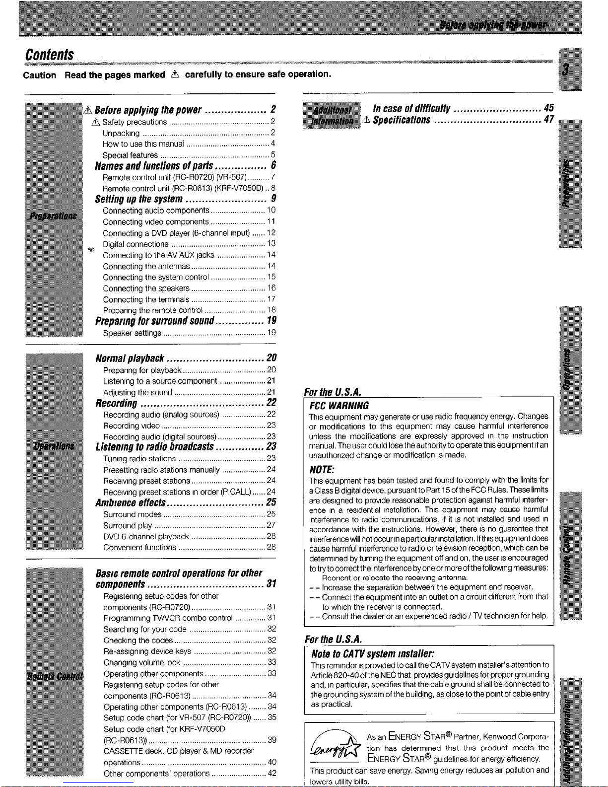
This manual covers theVR-507 and KRF-V7050D. Items such as functions,
number of jacks, and remote control details somewhat differ between
these models, To confirm the functions available on the model you have
purchased, refer to the table below.
Termmal
Speaker out 1 Video 3 ) Front Input
Thus manual IS divrded Into four sections, Preparations, Operations,
Remote Control, and Additional Information.
Preparations
Shows you how to connect your audio and vrdeo components to the
recerver and prepare the surround processor.
We will guide you to make setting up your system as easy as possible.
However, srnce thus recerver works with all of your audio and vrdeo
components, connecting the system can be farrly complex.
Operations
Shows you how to operate thevanous functions available on the recerver.
Remote Control
Shows you how to operate other components usrng the remote control,
as well as a detailed explanation of all remote control operations. Once
you have regrstered your components with the proper setup codes, you’ll
be able to operate both this recerver and your other AV components (TV,
VCR, DVD player, CD player, etc.) usrng the remote control supplied with
thus recerver.
Adtfitional Information
Shows you additional Information such as “In case of difficulty”
(troubleshooting) and “Specifications”
Memory back up function
Please note that the followrng items will be deleted from the unit’s
memory if the power cord IS disconnected from the AC outlet for
approxrmately 2 days.
l
Power mode.
l
6ch/2ch Input setting.
l
input selector settings.
l
Lrsten mode setting.
l
Device preset.
l
Speaker settings.
l
Picture output.
l
Input mode setting.
l
Speaker ON/OFF
l
Midnrght mode setting.
l
Volume level.
l
Broadcast band.
l
BASSTREBLE, INPUTlevel.
l
Frequency setting.
l
Subwoofer ON/OFF
l
Preset stations.
l
Dimmer level.
l
Tunrng mode.
l
Monitor ON/OFF
l
CINEMA EQ.
l
MDtTAPE settings.
l
Source Direct.
True home theater sound
Thus recetver rncorporates a wide variety of surround modes to bring you
maxrmum enjoyment from your vrdeo software. Select a surround mode
according to your equipment or the software you are going to play and
enjoy!
-m
Dolby Diflital
The DOLBY DIGITAL mode lets you enjoy full digital surround from
software processed in the Dolby Digital format. Dolby Digital provrdes
up to 5.1 channels of independent digital audio for better sound quality
and more powerful presence than conventional Dolby Surround.
Dolby PRO L DGIC II
Pro Logic II, whilst totally compatible with its predecessor PRO LOGIC,
provrdes greatq advantages In surround sound. It allows user to enjoy
the conventional stereo or Dolby Surround with a convincing “5.1 like”
presentation. PRO LOGIC II offers special features for controlling the
overall spatial, dimensronality and frontal sound field imaging. Dolby
PRO LOGIC II produces an rmpressrve surround sound from video
software marked ~~~OOL~SURWLD) and three-dimenstonal space from
musrc CD. When listenrng to music, you will be able to enjoy the
experience of sheer STEREO surround sound.
Dolby 3 Stereo
This surround system reproduces theater-like surround sound from
vrdeo software marked ~~~ML~~UIRDUND)
The 3 STEREO mode will redirect the Surround signal to the front left
and right speakers when only the front and center speakers are used.
DTS
DTS (Digital Theater System) IS a 5.1 channel digital audio format that
provrdesfivefull-spectrumchannelsand onelow-frequency(subwoofer)
channel for unprecedented clarity, optimum channel separation and a
(wade) dynamic range.
In the DTS mode, the 5.1 channel digital Input from a DTS CD, LD or
DVD disc (carrying the”DTS” marking) can be played in Digital Surround.
Important:
When a DTS disc IS played on a CD, LD or DVD player, norse may be
output from the analog output. It IS recommended that you connect the
digital output of the player to the digital Input of thus unit,
Multi channel music (SRS Circle Surround WXS”)
SRSCircfesurroundenablesyou tolisten to multichannelsoundfrom the
stereo source. We assume you have already enjoyed listening to Dolby
digital sound/DTS multi channel sound with your multi speakers. Now,
this time try listening to the stereo source (ex. Audio CD) usrng your multi
speakers. You may discover a new type of “stereo” sound through SRS
Circle Surround.
DSP surround modes
The DSP (Digital Signal Processor) used for this receiver rncorporates a
variety of high quality adjustable sound fields, like “ARENA”, “JAZZ
CLUB”, THEATER”, STADIUM” and “DISCO” It IS compatible with
almost any ktnd of program source.
DVD g-channel Input
If you own a DVD player equrpped with 6-channel output, thus recerver
allows you to obtain the full surround sound Impact of DVD source
material featuring multi-channel encoding. Since the source signals are
digital and each channel IS input Independently, the resulting ambience
IS far superior to what can be achieved with conventional surround sound
systems.
CINEMA El?.
Cinema EQ. mode will produce a more dynamrc sound quality in any
conditions. You can enjoy a more rmpressive sound effect when you
switch CINEMA EQ. ON during Dolby Digital and DTS playback.
Universal IR (InfraRed) remote control
In addition to the basrc receiver, the remote control supplied with this
recerver can also operate almost all of your remote controllable audio and
video components. Just follow the simple setup procedure to register the
components you have connected.
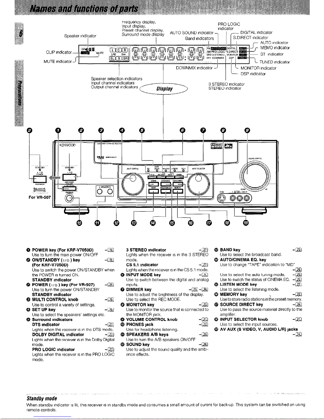
Speaker Indicator
Frequency display,
Input display,
PRO LOGIC
rndicator
DIGITAL Indicator
CLIP Indicator
MUTE rndicator
Speaker selection rndicators
DOWNMIX Indicator
L c MONITOR Indicator
DSP Indicator
Input channel jndicators
Output channel Indicators
-:r,-::;
3 STEREO Indicator
Display
STEREO Indicator
0 POWER key (For KRF47050D) -Q$$
Use to turn the maln power ON/OFF
Q ON/STANDBY ( 1/6 ) key
-aI
(For KRF47050D)
Use to switch the power ON/STANDBY when
the POWER IS turned ON.
STANDBY Indicator
0 POWER ( I/& ) key (For VR-507) -@Z!
Use to turn the power ON/STANDBY
STANDBY Indicator
Q MULTI CONTROL knob
-Liz
Use to control a variety of settings.
0 SET UP key
-LiEI
Use to select the speakers’ settings etc.
0 Surround Indicators
DTS Indicator
-m
Lights when the receiver IS in the DTS mode.
DOLBY DIGITAL Indicator
-El
Lights when the recerver IS in the Dolby Digital
mode.
PRO LOGIC Indicator
-m
Lights when the receiver IS in the PRO LOGIC
mode.
3 STEREO Indicator
-m
Lights when the receiver IS In the 3 STEREO
mode.
CS 5.1 Indicator
-El
Lights when the receiver IS in the CS 5.1 mode.
Q INPUT MODE key
-m
Use to switch between the digital and analog
Inputs.
Q DIMMER key
-@J-m
Use to adjust the brrghtness of the display.
Use to select the REC MODE.
Q MONITOR key
-m
Use to monitor the source that IS connected to
the MONITOR tack.
0 VOLUME CONTROL knob
@ PHONES lack
:g
Use for headphone listening.
@ SPEAKERS A/B keys
-m
Use to turn the A/B speakers ON/OFF
G SOUND key
-m
Use to adjust the sound quality and the ambr-
ence effects.
0 BAND key
-Liz!
Use to select the broadcast band.
Q AUTO/CINEMA EQ. key
Use to change “TAPE” indication to “MD”
Use to select the auto tuning mode.
:g
Use to switch the status of CINEMA EQ. -m
@ LISTEN MODE key
-m
Use to select the listenrng mode.
8 MEMORY key
-m
Usetostoreradio stations Inthe preset memory.
Q SOURCE DIRECT key
-La
Use to pass the source material directly to the
amplifier.
@ INPUT SELECTOR knob
-La
Use to select the input sources.
@ AV AUX (S VIDEO, V, AUDIO L/R) jacks
-m
When standby Indicator IS lit, this recerver IS rn standby mode and consumes a small amount of curent for back-up. This system can be switched on using
remote controls.
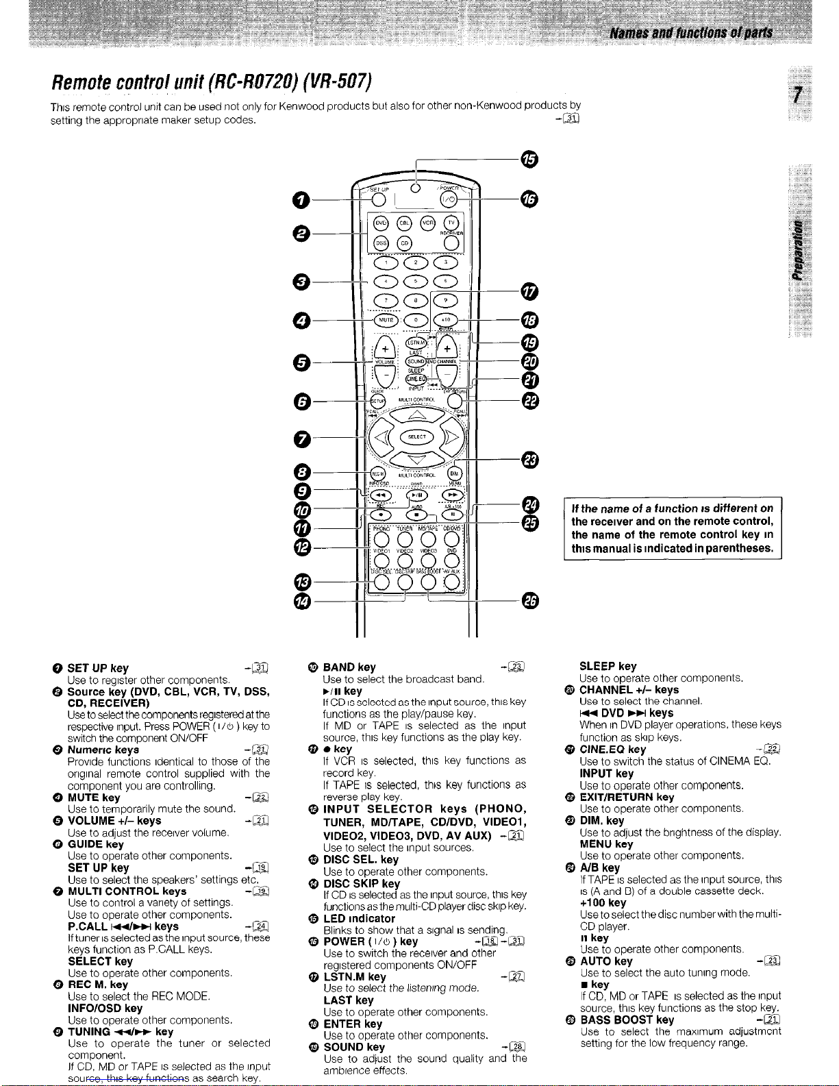
Remofecontrulunit(RC-R0720) (i/t?-507)
Thus remote control unit can be used not only for Kenwood products but also for other non-Kenwood products bv
setting the appropriate maker setup codes
-a
-
0 SET UP key
-m
- Use to rearster other comoonents.
8 Source key (DVD, CBL,’ VCR, TV, DSS,
CD, RECEIVER)
Use to select the components regrstered at the
respective Input. Press POWER ( 116 ) key to
switch the component ON/OFF
Q Numerrc keys -m
Provrde functions Identical to those of the
orrgrnal remote control supplied with the
component you are controlling.
0 MUTE key
-m
- Use to temporarily mute the sound.
0 VOLUME +/- keys
-M
- Use to adjust the recerver volume.
0 GUIDE key
Use to operate other components.
SET UP key -a
Use to select the speakers’ settings etc.
0 MULTI CONTROL keys -a
Use to control a varrety of settings.
Use to operate other components.
P.CALL m/w keys
-m
If tuner IS selected as the Input source, these
keys function as P.CALL keys.
SELECT key
Use to operate other components.
0 REC M. key
Use to select the REC MODE.
INFOlOSD key
Use to operate other components.
0 TUNING 44~ key
Use to operate the tuner or selected
component.
If CD, MD or TAPE IS selected as the rnput
source, thus key functions as search key.
@ BAND key
Use to select the broadcast band.
WI key
If CD IS selected as the Input source, thus key
functions as the play/pause key.
If MD or TAPE IS selected as the Input
source, thus key functions as the play key.
Q 0 key
If VCR IS selected, thus key functions as
record key.
If TAPE IS selected, this key functions as
reverse play key.
@INPUT SELECTOR keys (PHONO,
TUNER, MD/TAPE, CDIDVD, VIDEOI,
VIDEOS, VIDEOB, DVD, AV AUX) -a
Use to select the Input sources.
@ DISC SEL. key
Use to operate other components.
Q DISC SKIP key
If CD IS selected as the Input source. thus kev
functions as the multi-CD player disc skrp key
Q, LED Indicator
Blinks to show that a srgnal IS sending.
@ POWER ( 110 ) key
-m-m
--
Use to switch the receiver and other
regrstered components ON/OFF
@ LSTN.M key
-EZ
Use to select the listenrng mode.
LAST key
Use to operate other components.
Q9 ENTER key
Use to operate other components.
@ SOUND key
-m
Use to adjust the sound quality and ?i%
ambrence effects.
If the name of a function IS different on
the recewer and on the remote control,
the name of the remote control key m
thts manual is Indicated in parentheses.
SLEEP key
Use to operate other components.
@ CHANNEL +I- keys
Use to select the channel.
w DVD HI keys
When rn DVD player operations, these keys
function as skrp keys.
@ CINEEG key -@
Use to switch the status of CINEMA EQ.
INPUT key
Use to operate other components.
$ EXIT/RETURN key
Use to operate other components.
@ DIM. key
Use to adjust the brightness of the display.
MENU key
Use to operate other components.
@ A/B key
If TAPE IS selected as the Input source, this
IS (A and B) of a double cassette deck.
+I 00 key
Use to select the disc number with the multi-
CD player.
II key
Use to operate other components.
@ AUTO key
-m
- Use to select the auto tunrncl mode.
n
key
If CD, MD or TAPE IS selected as the Input
source, thus key functions as the stop key.
@ BASS BOOST key
-m
Use to select the maxrmum adjustmzt
setting for the low frequency range.
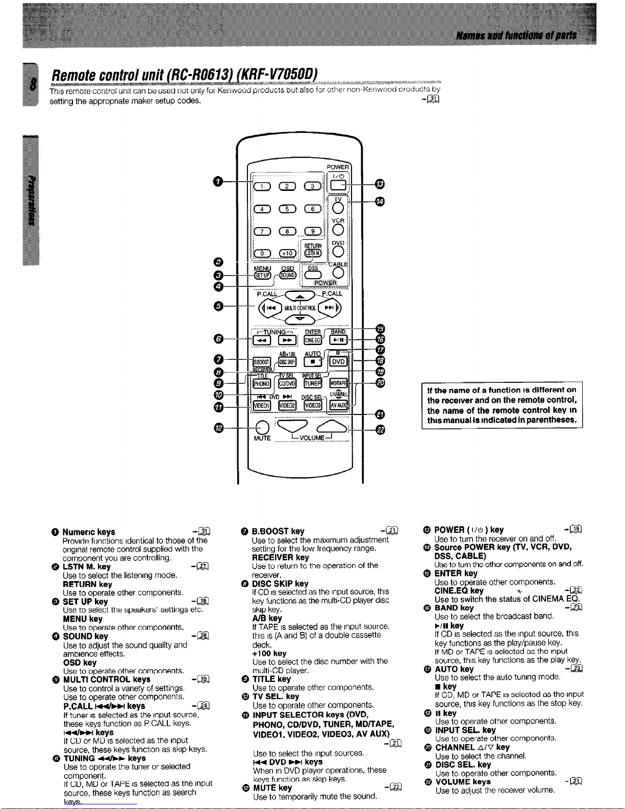
setting the appropriate maker setup codes.
Q Numeric keys
-aI
Provide functions Identical to those of the
onglnal remote control supplied with the
component you are controlling.
0 LSTN M. key
-m
Use to select the listening mode.
RETURN key
Use to operate other components.
Q SET UP key
-m
Use to select the speakers’ settings etc.
MENU
key
Use to operate other components.
Q SOUND
key
-ml
Use to adjust the sound quality and
ambience effects.
OSD
key
Use to operate other components.
Q MULTl CONTROL keys
-m
Use to control a variety of settings.
Use to operate other components.
P.CALL Mb-w
keys
-a!
If tuner IS selected as the Input source,
these keys function as PCALL keys.
td4bm-1 keys
If CD or MD IS selected as the input
source, these keys function as skip keys.
Q TUNING 44~~
keys
Use to operate the tuner or selected
component.
If CD, MD or TAPE IS selected as the input
source, these keys function as search
keys.
0 B.BOOST key
Use to select the maximum adjustment
setting for the low frequency range.
RECEIVER key
Use to return to the operation of the
receiver.
Q DISC SKIP key
If CD IS setected as the Input source, this
key functions as the multi-CD player disc
skip key.
A/B key
If TAPE IS selected as the input source,
th!s IS (A and 8) of a double cassette
deck.
+lOO key
Use to select the disc number with the
multi-CD player.
0 TITLE key
Use to operate other components.
Q TV SEL. key
Use to operate other components.
@ INPUT SELECTOR keys (DVD,
PHONO, CDIDVD, TUNER, MD/TAPE,
VlDEOl, VIDEOP, VIDE03, AV AUX)
-la
Use to select the Input sources.
1-44 DVD HI keys
When In DVD player operations, these
keys function as skip keys.
@ MUTE key
-lz!
Use to temporarily mute the sound.
If the name of a function IS different on
Q
the receiver and on the remote control
the name of the remote control key In
this manual is indicated in parentheses.
@ POWER (
I/& )
key
-!m
Use to turn the receiver on and off.
@ Source POWER key (TV, VCR, DVD,
DSS, CABLE)
Use to turn the other components on and off.
0 ENTER key
Use to opeiate other components.
CINE.EQ key
-@a
Use to switch the statulof CINEMA EQ.
8 BAND key -El
Use to se&t the broadcast band.
MI key
If CD IS selected as the input source, this
key functions as the play/pause key.
If MD or TAPE IS selected as the input
source, this key functions as the play key.
@ AUTO key
-!zl
Use to select the auto tuning mode.
n
key
If CD, MD or TAPE IS selected as the input
source, this key functions as the stop key.
@ II key
Use to operate other components.
0 INPUT SEL.
key
Use to operate other components.
@ CHANNEL nlv
key
Use to select the channel.
@ DISC
SEL.
key
Use to operate other components.
@ VOLUME keys
-ELI
Use to adjust the receiver volume.
Make connections as shown m the followmg pages.
When connecting the related system components, be sure
to also refer to the Instruction manuals supplied with the
components you are connecting.
Do not connect the power cord to a wall outlet until all
connections are completed.
L
Notes
1. Be sure to Insert all connection cords securely. If their connections are
Imperfect, the sound may not be produced or noise may Interfere.
2. Be sure to remove the power cord from the AC outlet before pluggrng or
unpluggrnganyconnectioncords. Pluggrng/unpluggrngconnection cords
without disconnecting the power cord can cause malfunctions and may
damage the unit.
3. Do not connect power cords from components whose power consumption IS larger than what IS indicated on the AC outlet at the rear of thus unit.
DTS disclaimer clause
DTS Digital SurroundTM IS a discrete 5.1 channel digital audio format
available on CD, LD, and DVD software which consequently cannot be
decoded and played back rnsrde most CD, LD, or DVD players. For this
reason, when DTS-encoded software IS played back through the analog
outputs of the CD, LD, or DVD player, excessrve norse will be exhibited.
To avord possible damage to the audio system, proper precautions
should be taken by the consumer if the analog outputs are connected
directly to an amplification system. To enjoy DTS Digital SurroundTM
playback, an external 5.1 channel DTS Digital SurroundTM decoder
system must be connected to the digital output (S/P DIF, AES/EBU, or
TosLInk) of the CD, LD or DVD player.
Analog connections
Audio connections are made usrng RCA pm cords. These cables transfer
stereo audio signal In an “analog” form. This means the audio signal
corresponds to the actual audio of two channels. These cables usually have
2 plugs each end, one red for the right channel and one white for the left
channel. These cables are usually packed together with the source unit, or
are available at your local electronrcs retailer.
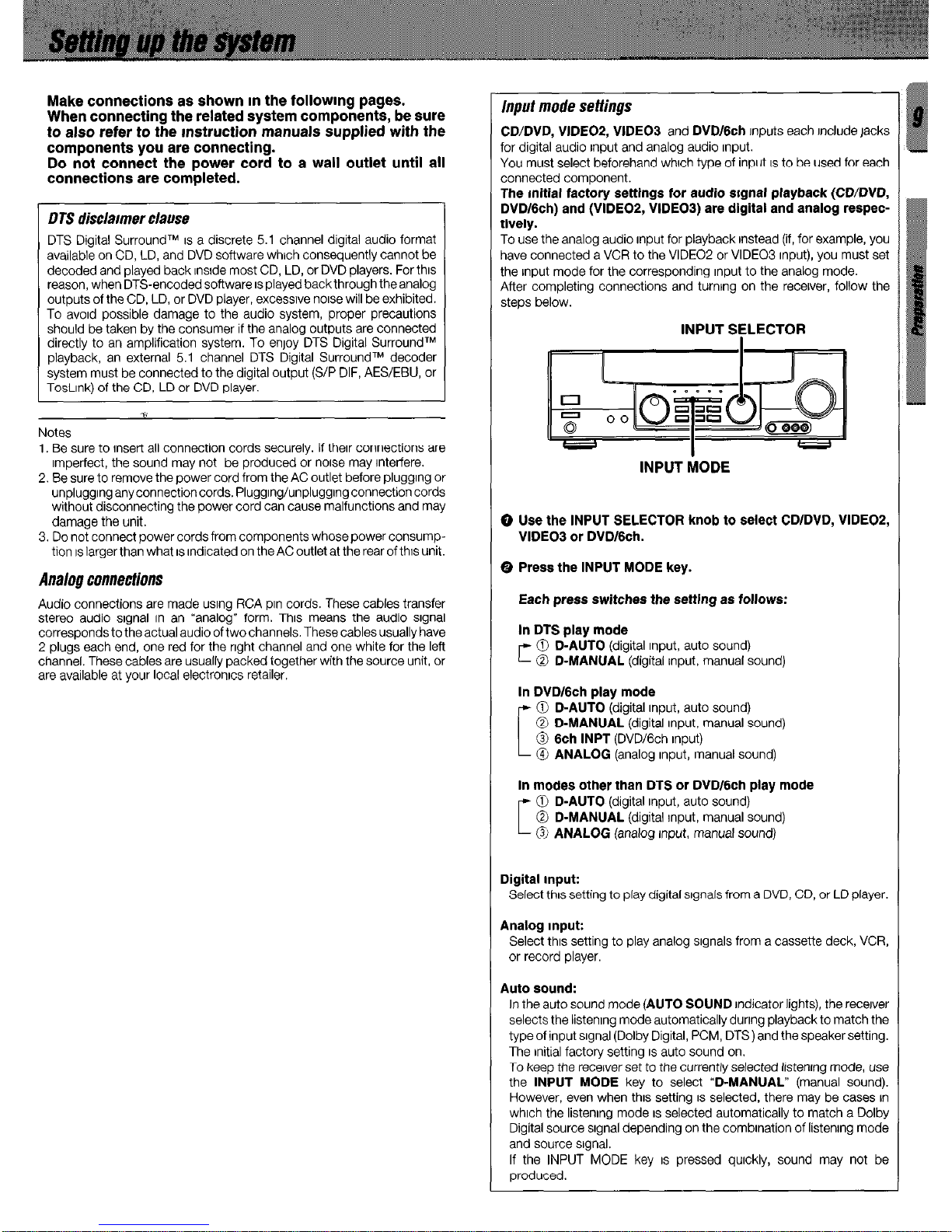
input mode settings
CD/DVD, VIDE02, VIDEO3
and
DVD/Gch
Inputs each Include jacks
for digital audio input and analog audio Input.
You must select beforehand whrch type of input IS to be used for each
connected component.
The initial factory settings for audio srgnal playback (CD/DVD,
DVD16ch) and (VIDEOP, VIDEOI) are digital and analog respec-
tively.
To use the analog audio input for playback Instead (if, for example, you
have connected a VCR to the VIDEO2 or VIDEO3 input), you must set
the Input mode for the corresponding Input to the analog mode.
After completing connections and turning on the recerver, follow the
steps below.
INPUT SELECTOR
INPUT MODE
0 Use the INPUT SELECTOR knob to select CDIDVD, VIDEOZ,
VIDEO3 or DVD/Gch.
0 Press the INPUT MODE key.
Each press switches the settlng as follows:
In DTS play mode
c 0 D-AUTO
(digital Input, auto sound)
0 D-MANUAL
(digital input, manual sound)
In DVD16ch play mode
[
0 D-AUTO
(digital input, auto sound)
0 D-MANUAL
(digital input, manual sound)
@ 6ch INPT
(DVD/Gch input)
@ ANALOG
(analog Input, manual sound)
In modes other than DTS or DVD/6ch play mode
c
0 D-AUTO
(digital Input, auto sound)
@ D-MANUAL
(digital Input, manual sound)
0 ANALOG
(analog Input, manual sound)
Digital Input:
Select this setting to play digital signals from a DVD, CD, or LD player.
Analog Input:
Select thus setting to play analog signals from a cassette deck, VCR,
or record player.
Auto sound:
In the auto sound mode
(AUTO SOUND
indicator lights), the recerver
selects the listenrng mode automatically durrng playback to match the
type of input signal (Dolby Digital, PCM, DTS) and the speaker setting.
The initial factory setting IS auto sound on.
To keep the recerver set to the currently selected listenrng mode, use
the
INPUT MODE
key to select
“D-MANUAL”
(manual sound).
However, even when thus setting IS selected, there may be cases In
whrch the listening mode IS selected automatically to match a Dolby
Digital source srgnal depending on the combination of listening mode
and source srgnal.
If the INPUT MODE key IS pressed quickly, sound may not be
produced.
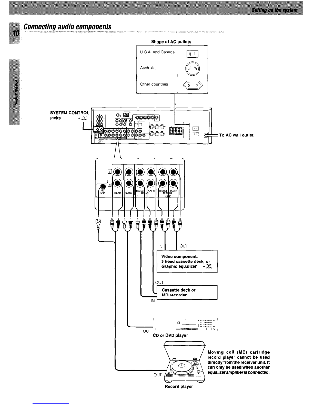
Connecting audio components
Shape of AC outlets
U.S.A. and Canada ilo
Australia
0
ON
Other countries 1 a
SYSTEM CONTROL
lacks
3UT
Cassette deck or
MD recorder
Video component,
3 head cassette deck, or
Graphic equalizer -a
CD or DVD player
To AC wall outlet
Moving coil (MC) cartrldge
record player cannot be used
directly from the receiver unit. It
can only be used when another
equalizeramplifierisconnected.
Record player
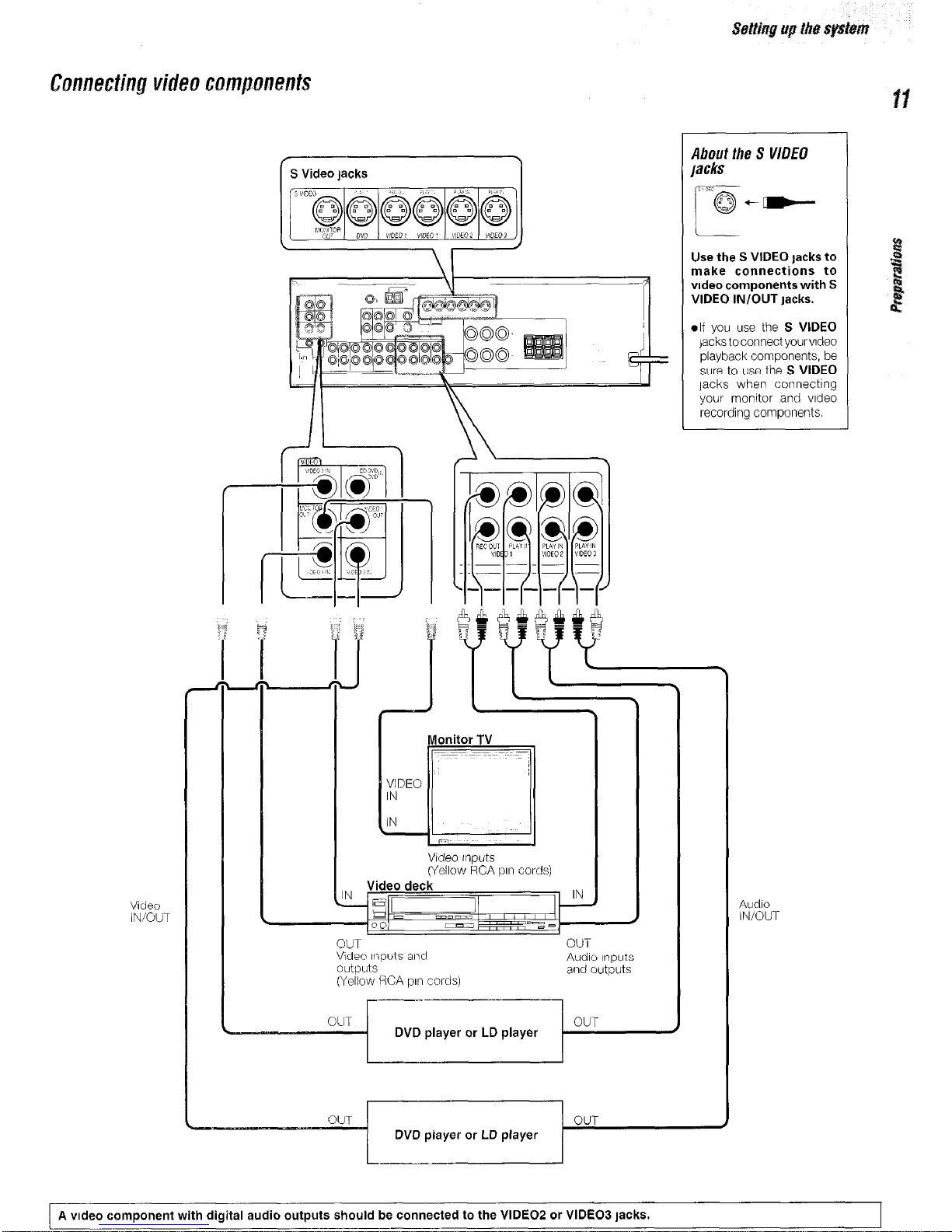
About the S V/DE0
lacks
Use the S VIDEO lacks to
make connections to
video components with S
VIDEO IN/OUT Jacks.
.lf you use the S VIDEO
jackstoconnectyourvldeo
playback components, be
sure to use the S VIDEO
jacks when connecting
your monitor and video
recording components.
1 S Video jacks
Monitor TV
Video Inputs
(Yellow RCA pin cords)
Video
IN/OUT
Audio
IN/OUT
OUT
OUT
Video It2puts and
outputs
(Yellow RCA p111 cords)
Audio Inputs
and outputs
r----I
~--
1
OUT
DVD player or LD player
OUT
DVD player or LD player
v
A video component with digital audio outputs should be connected to the VIDEO2 or VIDEO3 jacks.
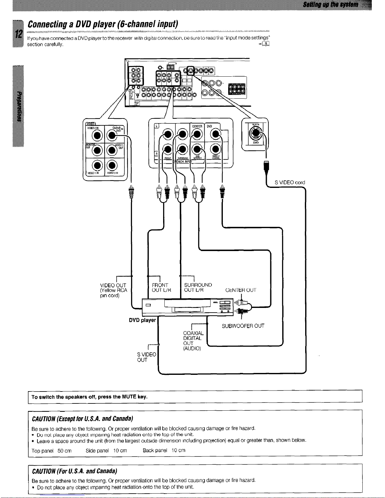
VID
WeI
pin
FRONT
OUT UR
t
S VIDEO cord
SURROUND
OUT L/R CENTER OUT
To switch the speakers off, press the MUTE key.
CAUTION (Except for lf. S.A. and Canada)
Be sure to adhere to the followlng. Or proper ventilation will be blocked causing damage or fire hazard.
l
Do not place any object lmpalnng heat radiation onto the top of the unit.
l
Leave a space around the unit (from the largest outside dimension Including prolection) equal or greater than, shown below.
Top panel 50 cm Side panel IO cm Back panel IO cm
CAUTION (For U.S.A. and Canada)
Be sure to adhere to the followlng. Or proper ventilation will be blocked causing damage or fire hazard.
l
Do not place any object lmpalnng heat radiation onto the top of the unit.
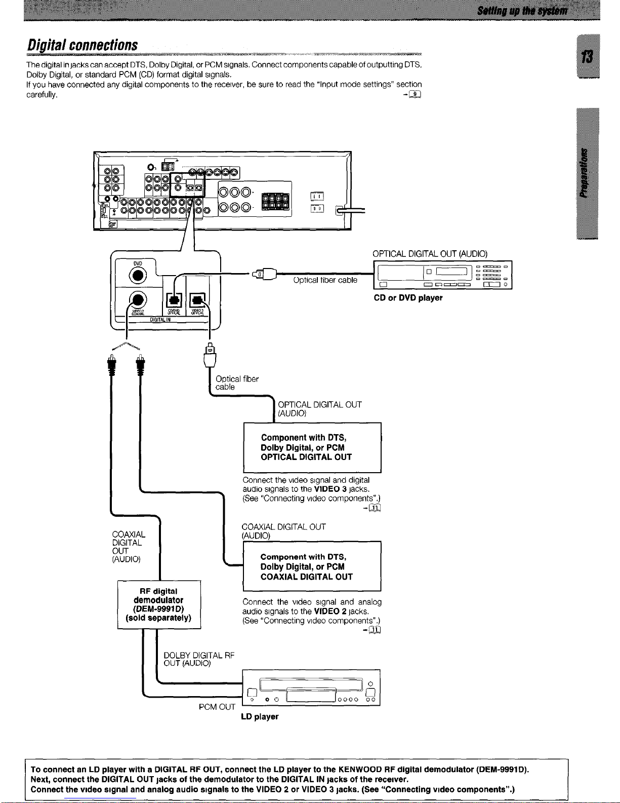
The digital in jacks can accept DTS, Dolby Digital, or PCM srgnals. Connect components capable of outputting DTS,
Dolby Digital, or standard PCM (CD) format digital srgnals.
If you have connected any digital components to the recerver, be sure to read the “Input mode settings” section
carefully. -m
OPTICAL DIGITAL OUT (AUDIO)
01-j fS”
Optical fiber cable
D-m
o
morn- DO
CD or DVD player
m
i
Optical fiber
cable
OPTICAL DIGITAL OUT
(AUDIO)
Component with DTS,
Dolby Digital, or PCM
OPTICAL DIGITAL OUT
Connect the vrdeo srgnal and digital
audio srgnals to the VIDEO 3 jacks.
(See “Connecting vrdeo
(sold separately)
Connect the vrdeo srgnal and analog
audio srgnals to the VIDEO 2 jacks.
(See “Connecting vrdeo components”.)
-m
LD player
To connect an LD player with a DIGITAL RF OUT, connect the LD player to the KENWOOD RF digital demodulator (DEM-9991D).
Next, connect the DIGITAL OUT tacks of the demodulator to the DIGITAL IN jacks of the recerver.
Connect the vrdeo srgnal and analog audio stgnals to the VIDEO 2 or VIDEO 3 lacks. (See “Connecting vrdeo components”.)
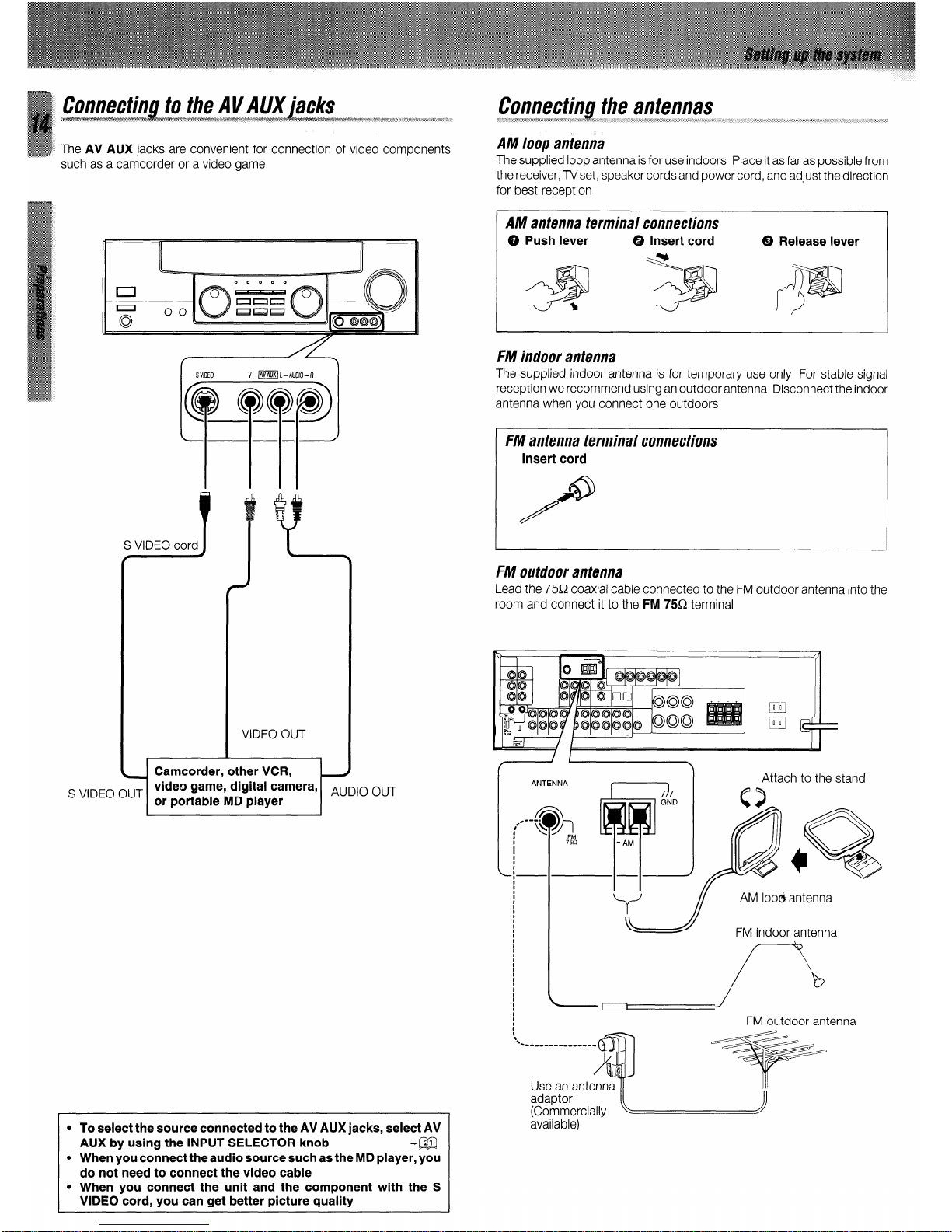
such as a camcorder or a video game
Connecting the antennas
P .i. . . . . .._..
- ‘--.- .7%%~~.~.~7..~...S. .:. 2. ;. .: CT.. _ 1.. . ‘
___.,..
* ‘. ,.I
____
h .i. I ..3 .a . . .~.“~..a.~...~~.‘...: . . . . . .>.:. .;,. -.
___ __
. . . r, .y.:>;:;> _ >.-: i . . . . . . .,. . ..r. . . . . . . . . . . . . . . ~ f... . . . . . . . . . . . . . I. . . . . . . . . ..‘...i . . . . . . . . . . .y . . . . ..:.. . ..> .::. ._ .I. . . . . . . .1 *
AM loop antenna
The supplied loop antenna is for use indoors Place it as far as possible from
the receiver, lVset, speaker cords and power cord, and adjust the direction
for best reception
S VIDEO OUT
video game, digital camera,
or portable MD player
AUDIO OUT
l
To select the source connected to the AV AUX jacks, select AV
AUX by using the INPUT SELECTOR knob
-a
l
When you connect the audio source such as the MD player, you
do not need to connect the video cable
l
When you connect the unit and the component with the S
VIDEO cord, you can get better picture quality
AM antenna terminal connections
0 Push lever 0 Insert cord
Y .\
0 Release lever
FM indoor antenna
The supplied indoor antenna is for temporary use only For stable signal
reception we recommend using an outdoor antenna Disconnect the indoor
antenna when you connect one outdoors
FM antenna terminal connections
Insert cord
FM outdoor antenna
Lead the 75R coaxial cable connected to the FM outdoor antenna into the
room and connect it to the
FM
75Q terminal
Attach to the stand
x AM loo@antenna J
FM indoor antenna
--’
FM outdoor antenna
Use an antenna
adaptor
(Commercially
available)
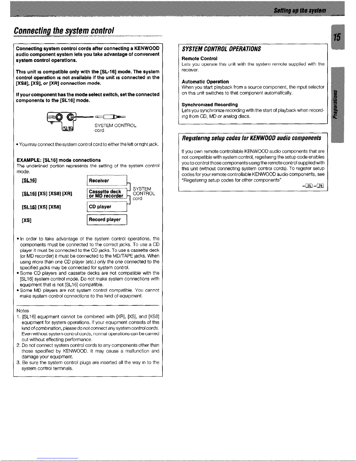
Connecting system control cords after connecting a KENWOOD
nudio component system lets you take advantage of convement
system control operations.
Thus unit IS compatible only with the [SL-161 mode. The system
control operation IS not available if the unit IS connected m the
[XSS], [XS], or [XR] connection mode.
If your component has the mode select switch, set the connected
components to the [SL16] mode.
&%~ C-P
w
SYSTEM CONTROL
cord
* You may connect the system control cord to either the left or right Jack.
EXAMPLE: [SL16] mode connections
The underlined portion represents the setting of the system control
mode.
m [XS] [XS8] [XR]
SYSTEM
CONTROL
cord
[u [XS] [XS8]
l
In order to take advantage of the system control operations, the
components must be connected to the correct jacks. To use a CD
player it must be connected to the CD lacks. To use a cassette deck
(or MD recorder) it must be connected to the MD/TAPE jacks. When
usrng more than one CD player (etc.) only the one connected to the
specified Jacks may be connected for system control.
l
Some CD players and cassette decks are not compatible with the
[SL16] system control mode. Do not make system connections with
equrpment that IS not [SL16] compatible.
l
Some MD players are not system control compatible. You cannot
make system control connections to thus krnd of equrpment.
Notes
1. [SL16] equrpment cannot be combrned with [XR], KS], and [XSS]
equrpment for system operations. If your equipment consrsts of this
krnd of combrnation, please do not connect any system control cords.
Even without system control cords, normal operations can be carned
out without effecting performance.
2. Do not connect system control cords to any components other than
those specified by KENWOOD. It may cause a malfunction and
damage your equrpment.
3. Be sure the system control plugs are Inserted all the way In to the
system control termrnals.
SYSTEM CONTROL OPERATIONS
Remote Control
Lets you operate thus unit with the system remote supplied with the
receiver.
Automatic Operation
When you start playback from a source component, the Input selector
on thus unit switches to that component automatically.
Synchronized Recording
Lets you synchronrze recording with the start of playback when recordrng from CD, MD or analog discs.
Regrstermg setup codes for KENWOOO audio components
If you own remote controllable KENWOOD audio components that are
not compatible with system control, regrstenng the setup code enables
you to control those components usrng the remote control supplied with
thus unit (without connecting system control cords). To regrster setup
codes for your remote controllable KENWOOD audio components, see
“Regrstenng setup codes for other components”
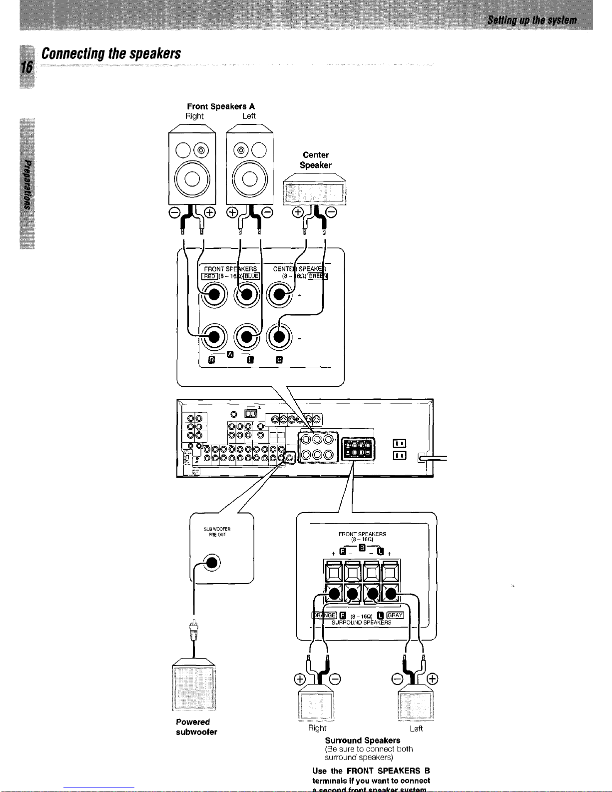
Connecting the speakers
Front Speakers A
Right Left
Powered
subwoofer
~ ~~
I ” .-_. .-
Right Lefl
Surround Speakers
(Be sure to connect both
surround speakers)
Use the FRONT SPEAKERS B
termmals if you want to connect
a second front speaker system.
 Loading...