

Kenwood VR-605, VR-615, KRF-V5060D, KRFW4060D, KRFW5560D Instruction Manual
...
KENWOOD
AUDIO VIDEO SURROUND RECEIVER
VR-605
VR-615
KRF-V5060D
KRFW4060D
KRFW5560D
INSTRUCTION MANUAL
KENWOOO CORPORATION
This instruction manual is for some models. Model availability and features
(functions) may differ depending on the country and sales area.
About the supplied remote control
Compared to standard remote controls, the remote control supplred wrth thus recerver has several
operatron modes. These modes enable the remote control to control other audio/vrdeo components. In
order to effectrvely use the remote control it IS Important to read the operatrng instructions and obtain a
proper understandrng of the remote control and how to swatch Its operatron modes (etc.).
Usrng the remote control wrthout completely understanding Its design and how to switch the operation
modes may result rn Incorrect operatrons
1
660-5197-20 02 B;
(K, P, T, M, Y, X, E2) $b:v:: 0109
Before applying the power
A Caution : Read this page carefully to ensure safe
operation.
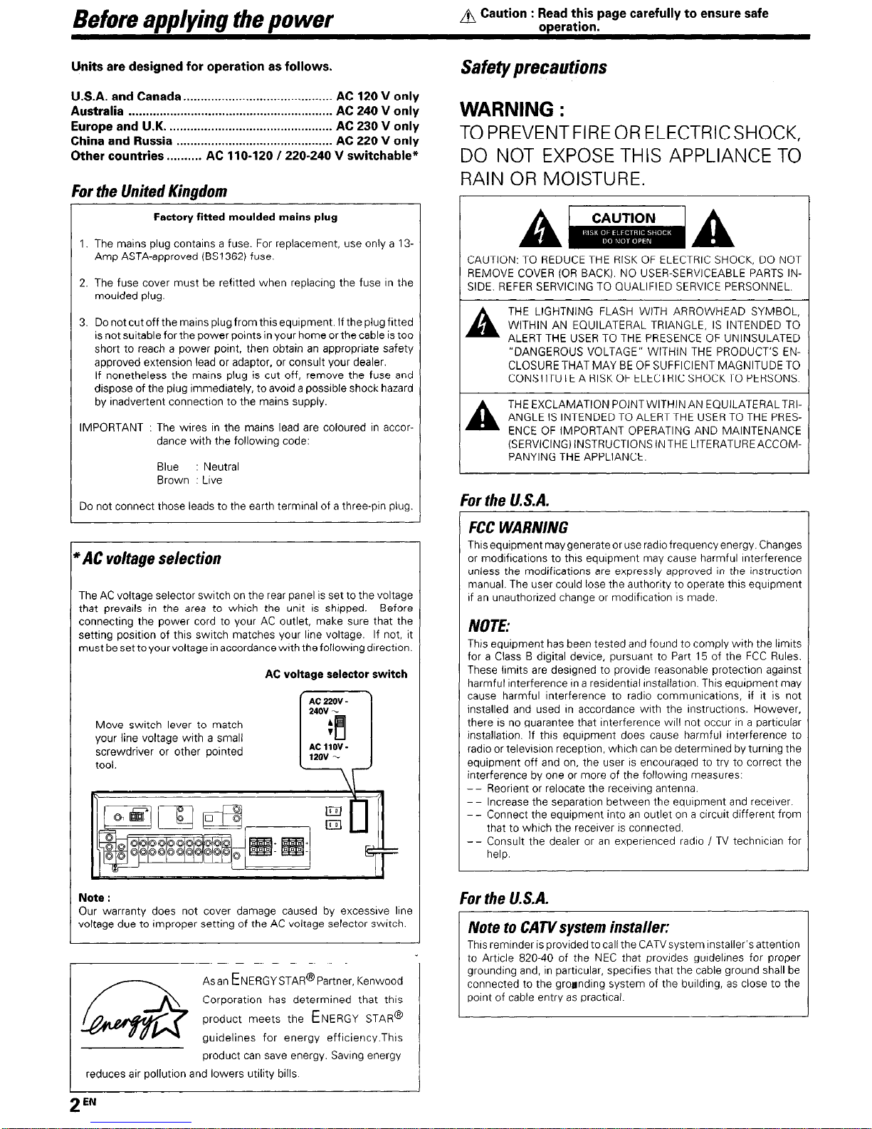
Units are designed for operation as follows.
U.S.A. and Canada.. ......................................... AC 120 V only
Australia
........................................................... AC 240
V only
Europe and U.K.
...............................................
AC 230 V only
China and Russia ............................................. AC 220 V only
Other countries.. ........
AC 110-120 1220-240 V switchable*
For the United Kingdom
Factory fitted moulded mains
plug
1. The mains plug contains a fuse. For replacement, use only a 13Amp ASTA-approved (BS1362) fuse.
2. The fuse cover must be refitted when replacrng the fuse rn the
moulded plug.
3. Do not cut off the mains plug from this equrpment. If the plug frtted
is not surtable for the power points in your home or the cable is too
short to reach a power point, then obtain an appropriate safety
approved extension lead or adaptor, or consult your dealer.
If nonetheless the marns plug is cut off, remove the fuse and
dispose of the plug immedrately, to avord a possible shock hazard
by inadvertent connectron to the mains supply.
IMPORTANT : The wires in the mains lead are coloured in accor-
dance wrth the followrng code:
Blue : Neutral
Brown : Love
Do not connect those leads to the earth terminal of a three-pm plug.
AC voltage selection
The AC voltage selector switch on the rear panel IS set to the voltage
that prevails in the area to which the unit is shipped. Before
connectrng the power cord to your AC outlet, make sure that the
setting position of this swatch matches your line voltage. If not, it
must besettoyourvoltage inaccordance wrth thefollowrngdrrectron.
AC voltage selector switch
Move swatch lever to match
your line voltage wrth a small
screwdriver or other pornted
tool.
El
m
II
4-
Note :
Our warranty does not cover damage caused by excessrve lrne
voltage due to rmproper setting of the AC voltage selector swatch.
Asan ENERGYSTAR@P~~~~~~, Kenwood
Corporation has determined that this
product meets the ENERGY STAR@
guidelines for energy effrciency.Thrs
product can save energy. Savrng energy
reduces air pollutron and lowers utility bills
Safety
precautions
WARNING :
TOPREVENTFIREORELECTRICSHOCK,
DO NOT EXPOSE THIS APPLIANCE TO
RAIN OR MOISTURE.
CAUTION: TO REDUCE THE RISK OF ELECTRIC SHOCK, DO NOT
REMOVE COVER (OR BACK). NO USER-SERVICEABLE PARTS INSIDE. REFER SERVICING TO QUALIFIED SERVICE PERSONNEL.
A
THE LIGHTNING FLASH WITH ARROWHEAD SYMBOL,
WITHIN AN EQUILATERAL TRIANGLE, IS INTENDED TO
ALERT THE USER TO THE PRESENCE OF UNINSULATED
“DANGEROUS VOLTAGE” WITHIN THE PRODUCT’S ENCLOSURE THAT MAY BE OF SUFFICIENT MAGNITUDE TO
CONSTITUTE A RISK OF ELECTRIC SHOCKTO PERSONS.
A
THE EXCLAMATION POINTWITHINAN EQUILATERALTRC
ANGLE IS INTENDED TO ALERT THE USER TO THE PRESENCE OF IMPORTANT OPERATING AND MAINTENANCE
(SERVICINGjINSTRUCTIONSlNTHE LITERATUREACCOMPANYING THE APPLIANCE.
:or the U.S.A.
FCC WARNING
Thus equipment may generate or use radio frequency energy. Changes
or modrfications to thus equrpment may cause harmful Interference
unless the modifications are expressly approved rn the Instruction
manual. The user could lose the authorrty to operate this equipment
If an unauthorized change or modification IS made.
NOTE:
Thus equipment has been tested and found to comply with the lrmrts
for a Class B digital devrce, pursuant to Part 15 of the FCC Rules.
These lrmrts are designed to provide reasonable protection against
harmful Interference rn a residentral rnstallatron. This equipment may
cause harmful Interference to radio communrcations, if it IS not
installed and used rn accordance with the rnstructrons. However,
there is no guarantee that interference wrll not occur rn a particular
installatron. If this equrpment does cause harmful interference to
radio or televisron reception, whrch can be determined by turnrng the
equipment off and on, the user IS encouraged to try to correct the
interference by one or more of the followrng measures:
- - Reorient or relocate the recervrng antenna.
- - Increase the separatron between the equipment and recerver.
- - Connect the equipment Into an outlet on a crrcurt different from
that to whtch the recerver IS connected.
- - Consult the dealer or an experienced radio I TV technician for
help.
:or the U.S.A.
Note to CATVsystem installer:
Thus remrnder is provided to call the CATVsystem Installer’s attention
to Artrcle 820-40 of the NEC that provrdes gurdelrnes for proper
groundrng and, rn particular, specrfres that the cable ground shall be
connected to the groandrng system of the burlding, as close to the
pornt of cable entry as practrcal
2 lzN

Before applying the power
CoJrtents
Caution : Read the pages marked A carefully to ensure
safe operation.
r^
A Before applying the power . . . . . . . . . . . . . . . . . . . . . ..-.... 2
A Safety precautions
2
Unpackrng
3
How to use this manual 4
Specral features
Names and functions of parts . . . . . . . . . . . . . . . . . . . . . . . . . ::
Marn Unit 5
Remote control unrt (FiC-R0621) fVR-605/KRFV4060DiV5560D) and (RC-R0620) (VR-615/KRFV5060D) 6
Remote control unrt (RC-R0623) IKRF-V4060D/
V5560D) and (RC-R0622) (KRF-V5060D) (For the
r~~~#~
U K. and Europe only).
Setting up the system ..,..,..,....,.......................... ii
Connecting audrocomponents 9
Connectrng vrdeo components 10
Digital connectrons
11
Connectrng a DVD player (6.channel Input) (For
VR-615/KRF-V5060D only). 12
Connectrng the speakers 13
Connecting the terminals 14
Connectrng the antennas
.I4
Connectrng the system control 15
Preparing the remote control
16
Preparing for surround sound . . . . . . . . . . . . . . . . . . . . . . . 17
Speaker settrngs 17
Norma/playback . . . . . . . . . . . . . . . . . . . . . . . . . . . . . . . . . . . . . . . . . . . . . . 19
Preparing for playback 19
Lrstenrng to a source component 19
Adfustrng the sound
Recording . . . . . . . . . . . . . . . . . . . . . . . . . . . . . . . . . . . . . . . . . . . . . . . . . . . . . . . . . .
z
Recording audro (analog sources) 21
Recordrng vrdeo 21
Recording audro (drgrtal sources)
Listening to radio broadcasts . . . . . . . . . I..: .,..,..... ;;
Tuning (non-RDS) radio stations 22
Using RDS iRadIo Data System) (For the U K
and Europe only) 22
Presettrng radio statrons manually 23
Recervrng preset statrons 23
Recelvrng preset stations rn order fP.CALLI 23
Usrng the RDS DISPLAY key (For the U K and
Europe only) 24
Presettrng RDS statrons (RDS AUTO MEMORY1
(For the UK and Europe only) 24
Tuning by Program TYpe (PTY search) (For the
U K and Europe only)
Ambience effects . . . . . . . . . . . . . . . . . . . . . . . . . . . . . . ~..........,...
ii
Surround modes 26
Surround play
28
DVD 6-channel playback (For VR-615/KRFV5060D only). 29
Convenrent functions
29
Basicremotecontroloperationsforothercom-
ponents .,,.,,,.,,,,,,,,..........................,...,..,.....,...... 32
DVD player operation keys
32
CASSETTE deck, CD player & MD recorder
operatrons 33
tional
In case of difficulty.. ........................................ 34
Information
A Specifications .................................................. 36
Unpacking
Unpack the unit carefully and make sure that all accessories are present.
FM Indoor antenna (Ii AM loop antenna (I 1
For W-605, KRF-V4060D and KRF-V5660D
Remote control unrt (I) Batteries fRG/AA) (2)
RC-R0621
(m) 6j@
----- ---
For VR-615 and KRF-V5060D
Remote control unit (I) Batterres tRG/AA) (2)
RC-R0620
For KRF-V5060D (For the U.K. and Europe only)
Remote control unit (1) Batteries tRG/AA) (‘2)
RC-R0622
For KRF-V4060D and KRF-V5560D (For the U.K. and Europe onl
Remote control unit (1)
Batteries fRG/AA) (2)
RC-R0623
*AC plug adapter (11
“Usetoadapttheplugonthepow
cord to the shape of the wall outle
(Accessory only for regions wher
use IS necessary.)
If any accessorres are mrssrng, or if the unrt IS damaged or fails to operate,
notrfy your dealer rmmedrately If your unrt was shopped to you drrectly,
notrfy your shrpper rmmedrately Kenwood recommend that you retarn
the orrgrnal carton and packrng materials in case you need to move or shop
the unrt rn the future.
Keep this manual handy for future reference.
3
EN
Before em/vim the Dower
How to use this manual
Dolby Digital
This manual is drvided Into four sections, Preparations, Operations,
Remote Control, and Additional Informatron.
The DOLBY DIGITAL mode lets you enjoy full drgrtal surround from
software processed in the Dolby Drgrtal format Dolby Drgrtal provrdes up
to 5 1 channels of independent digital audro for better sound quality and
more powerful presence than conventronal Dolby Surround.
Preparations
Shows you how to connect your audro and video components to the
receiver and prepare the surround processor.
Since this receiver works with all of your audio and video components,
we will guide you rn setting up your system to be as easy as possrble
Operations
Dolby PRO LOGICII
Shows you how to operate the varrous functions available on the
receiver.
Remote Control
DOLBY PRO LOGIC II, whrlst totally compatible with Its predecessor
PRO LOGIC, provrdes greater advantages rn surround sound. It allows
user to enjoy the conventional stereo or Dolby Surround w&h a convrncing “5.1 like” presentation. PRO LOGIC
II
offers specral features for
controllrng the overall spatral, dimensronalrty and frontal sound field
rmagrng. PRO LOGIC
II
produces an impressive surround sound from
video software marked ml---f and three-dimensronal space
from musrc CD. When listening to musrc, you wrll be able to enjoy the
experrence of sheer STEREO surround sound
Shows you how to operate other components using the remote control,
as well as a detailed explanatron of all remote control operatrons. Once
you have registered your components with the proper setup codes, you’ll
be able to operate both this receiver and your other AV components (TV,
VCR, DVD player, CD player, etc.) usrng the remote control supplred wrth
this receiver.
Additional Information
DTS
Shows you additional information such as “In case of drffrculty”
(troubleshooting) and “Specificatrons”.
DTS (DIgItal Theater System) is a 5.1 channel digital audio format that
provides five full-spectrum channels and one low-frequency (subwoofer)
channel for unprecedented clarity, optrmum channel separation and a
(wade) dynamic range
In the DTS mode, the 5.1 channel drgrtal Input from a DTS CD, LD or DVD
disc (carrying the “DTS” marking) can be played in Drgrtal Surround.
Important
When a DTS disc is played on a CD, LD or DVD player, norse may be
output from the analog output. It IS recommended that you connect the
drgrtal output of the player to the drgrtal Input of thus unrt.
LISP surround modes
The DSP (Drgital Signal Processor) used for thus receiver rncorporates a
varrety of hrgh quality adjustable sound fields. lrke “ARENA”, “JAZZ
CLUB”, THEATER”, STADIUM” and “DISCO”. It IS compatible with
almost any krnd of program source.
Do not use contact cleaners because it could cause a malfunction. Be
may deform the plastic component.
DVD Bchannel input (For VR-615/KRF-V506OD only)
If you own a DVD player equipped with 6-channei output, thus recerver
allows you to obtarn the full surround sound Impact of DVD source
matenal featuring mulb-channel encodrng. Since the source srgnals are
drgrtal and each channel IS Input Independently, the resultrng ambience
1s far superior to what can be achieved wrth conventronal surround sound
systems.
Memory back up function
Please note that the following items wall be deleted from the unit’s
memory if the power cord is disconnected from the AC outlet for
approximately 1 day.
l
Power mode.
l
Input selector settings.
l
Prcture output.
l
Speaker ON/OFF.
l
Volume level.
l
BASS, TREBLE, INPUT level.
l
Dimmer level.
l
MD/TAPE settings.
l
Listen mode setting.
l
Speaker settings.
l
SW RE-MIX ON/OFF.
l
Distance settrng.
l
Input mode settrng.
l
Midnight mode setting.
l
PRO LOGIC II mode setting.
l
Broadcast band.
l
Frequency setting.
l
Preset stations.
l
Tunrng mode.
l
CINEMA EQ ON/OFF.
l
LOUDNESS ON/OFF
~p~ial features
True home theater sound
This receiver incorporates a wide varrety of surround modes to bring you
maximum enjoyment from your vrdeo software. Select a surround mode
according to your equipment or the software you are going to play and
enjoy!
-m
-
CINEMA EQ
Cinema EQ mode wrll produce a more dynamrc sound qualrty rn any
condibons. You can enjoy a more Impressive sound effect when you
swatch CINEMA ECI ON durrng Dolby Drgrtal and DTS playback.
Universal IR (InfraRed) remote control
In addrtron to the basrc receiver, the remote control supplred wrth thus
recerver can also operate almost all of your remote controllable audio and
video components. Just follow the simple setup procedure to regrster
the components you have connected
RDS (Radio Data System) tuner (For the U.K. and
Europe only)
The receiver is equipped with an RDS tuner that provides several
convenient tunrng functrons. RDS Auto Memory, to automatrcally preset
up to 40 RDS statrons broadcasting drfferent programs; statron name
display, to show you the name of the current broadcast station; and PTY
search to let you tune stations by program type.
PTY (Program Type) search (For the U.K. and Europe
onlv)
Tune the stations by specrfyrng the type of program you want to hear
.I
4
EN
Names and functions of Darts
Main Unit
Speak
er lndlcator MUTE rndrcator
CINEMA EQ rndrcator
I
Frequency drsplay,
Input drsplay,
Preset channel drsplay,
Surround mode drsplay
AUTO DETECT
rndrcator
DTS rndrcator 1 6CH INPUT rndrcator
I
Band rndrcators 7 1 1 / rDIGITAL indicator
TONE tndtcatot
J
LOUDNESS indrcatot
Speaker selectron rndrcators
J j ;;;;:,,:1,~f;~;~ 1 :‘;;;A
YGkHzfs rndrcator
n:_-I-..
t
c
DSP indicator
STEREO rndrcator
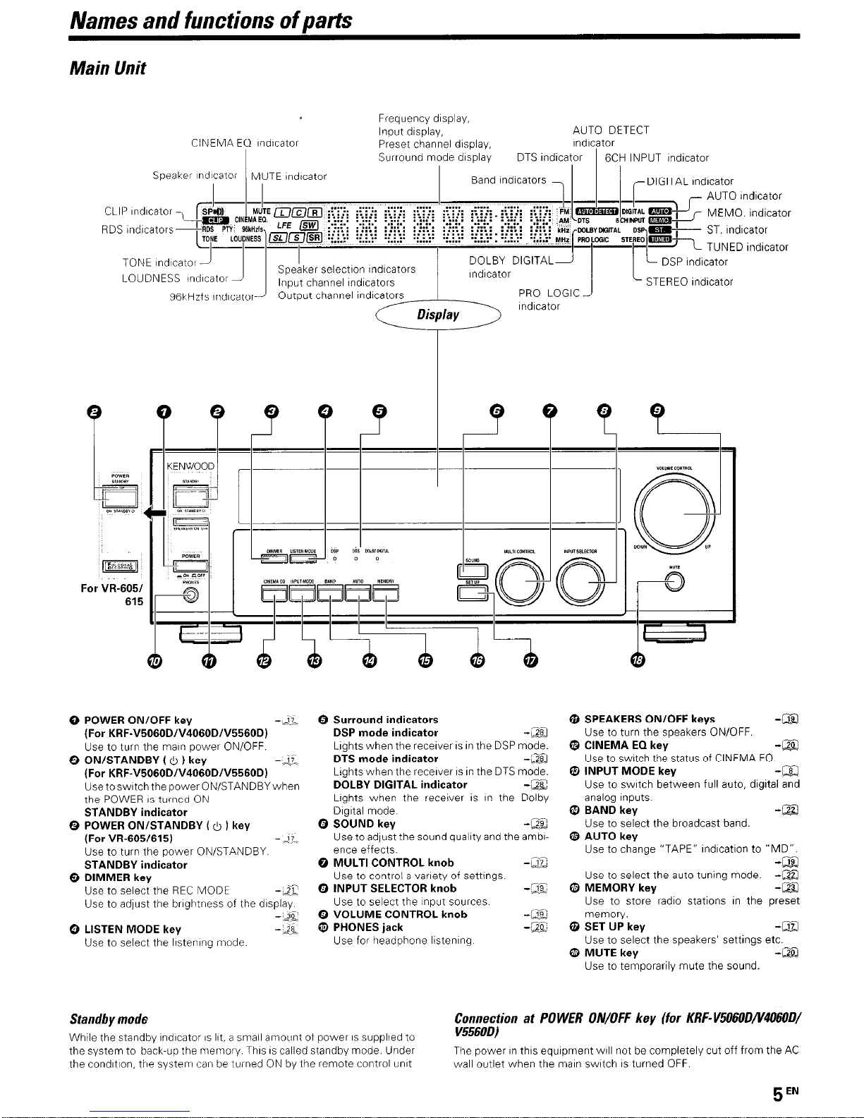
0 POWER ON/OFF key
-.2.
(For KRF-V5060DIV4060DIV5560D)
Use to turn the marn power ON/OFF.
@ ON/STANDBY ( 0 ) key
-.&
(For KRF-V5060DIV4060DIV5560D)
UsetoswrtchthepowerON/STANDBYwhen
the POWER IS turned ON
STANDBY indicator
0 POWER ON/STANDBY (0 ) key
(For VR-605/615) - 17
Use to turn the power ON/STANDBY
STANDBY indicator
Q DIMMER key
Use to select the REC MODE
-LX
Use to adjust the brrghtness of the drsplay
-*Jo’
0 LISTEN MODE key
Use to select the Irstenrng mode.
Standby mode
Whrle the standby rndrcator IS Irt, a small amotrnt of power IS supplied to
0 Surround indicators
DSP mode indicator
-ZQ
Lights when the recerver IS rn the DSP mode.
DTS mode indicator
-m
Ltghts when the receiver IS rn the DTS mode.
DOLBY DIGITAL indicator
-gC
Lights when the recefver IS rn the Dolby
Drgrtal mode
0 SOUND key -@Z
Use to adjust the sound qualrty and the ambrence effects.
0 MULTI CONTROL knob
-EZ
Use to control a variety of settings
0 INPUT SELECTOR knob -Z
Use to select the Input sources.
0 VOLUME CONTROL knob
-1%
“F--
0 PHONES jack -a
Use for headphone lrstenrng
@ SPEAKERS ON/OFF keys
-Qg
Use to turn the speakers ON/OFF.
a CINEMA EQ key
-m
Use to swatch the status of CINEMA EQ.
0 INPUT MODE key
-a
Use to switch between full auto, digital and
analog Inputs
@ BAND key
-La
Use to select the broadcast band.
@ AUTO key
Use to change “TAPE” r&cation to “MD”.
Use to select the auto tunrng mode.
@ MEMORY key
ZiiJ
Use to store radio stations rn the preset
memory.
@ SET UP key
-a
Use to select the speakers’ settings etc.
a MUTE key
-m
Use to temporarily mute the sound.
Connection at POWER ON/OFF key (for KRF-V606OD/V406OD/
V556OD)
the system to back-up the memory This IS called standby mode Under
The power rn this equrpment will not be completely cut off from the AC
the condrtron, the system can be turned ON by the remote control unrt
wall outlet when the marn switch IS turned OFF.
5
EN
Names and functions of parts
Remote control unit (RER0621) (l/t?-605/KRF- V406OWV556OD) and (RC-RO620) (VR-615/KRF-
l&MOD)
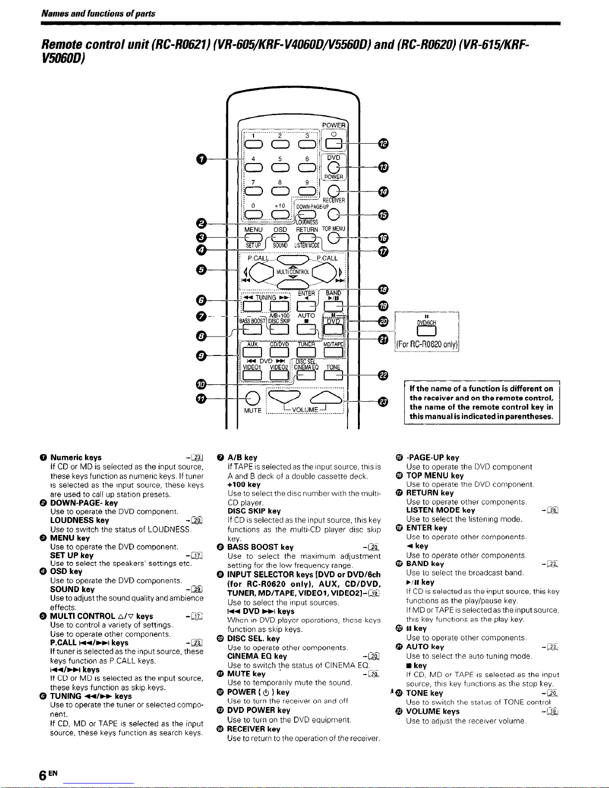
0 Numeric keys -a
If CD or MD is selected as the input source,
these keys functron as numerrc keys. If tuner
is selected as the input source, these keys
are used to call up statron presets.
0 DOWN-PAGE- key
Use to operate the DVD component.
LOUDNESS key
-m
Use to switch the status of LOUDNESS.
Q MENU key
Use to operate the DVD component.
SET UP key
-m
-
use to select tne speakers settrngs etc.
0 OSD kev
Use to operate the DVD components.
SOUND key
-Es
Use to adjust the sound quality and ambience
effects.
Q MULTI CONTROL A/V keys
-m
Use to control a variety of settings.
Use to operate other components.
P.CALL w/m keys
-m
If tuner is selected as the Input source, these
keys functron as P.CALL keys.
m/m keys
If CD or MD is selected as the input source,
these keys function as skip keys.
Q TUNING *I- keys
Use to operate the tuner or selected component.
If CD, MD or TAPE is selected as the input
source, these keys functron as search keys.
0 AIB key
If TAPE is selected as the Input source, thus IS
A and B deck of a double cassette deck.
+lOO key
Use to select the disc number with the multrCD player.
DISC SKIP key
If CD IS selected as the input source, thus key
functrons as the multr-CD player disc skrp
key.
Q BASS BOOST key
-m
Use to select the maxrmum adjustment
settrng for the low frequency range.
0 INPUT SELECTOR keys [DVD or DVD16ch
(for RCR0620 only), AUX, CD/DVD,
TUNER, MD/TAPE, VIDEOl, VIDEOZI-m
Use to select the Input sources.
I* DVD w kevs
When rn DVD pfaier operatrons. these keys
function as skip keys.
@ DISC SEL. key
Use to operate other components.
CINEMA EQ key
-a
Use to switch the status of CINEMA EQ.
@ MUTE key
-kQf
Use to temporarrly mute the sound.
@ POWER ( 0 ) key
Use to turn the receiver on and off
@ DVD POWER key
Use to turn on the DVD equtpment.
@ RECEIVER key
Use to return to the operation of the recerver.
If the name of a function is different on
the receiver and on the remote control,
the name of the remote control key in
this manual is indicated in parentheses.
I
63 -PAGE-UP key
Use to operate the DVD component
@ TOP MENU key
Use to operate the DVD component
@ RETURN key
Use to operate other components.
LISTEN MODE key
-LZZ
Use to select the listenrng mode.
0 ENTER key
Use to operate other components.
4 key
Use to operate other components
@ BAND key
Use to select the broadcast band.
~/II key
If CD IS selected as the input source, thus key
functrons as the play/pause key.
If MD or TAPE IS selected as the Input source,
thus key functrons as the play key.
@ II key
Use to operate other components.
@ AUTO key
-DE
-
Use to select the auto tunrng mode.
n
key
If CD, MD or TAPE IS selected as the Input
source, thus key functrons as the stop key
‘@ TONE key
-@L
Use to switch the status of TONE control
@ VOLUME keys
-Qg
Use to adjust the receiver volume
6
EN

Names and functions of Darts
Remote control unit (RC-R0623) (KRF- V406ODiV556OD) and (RC-RO622) (KRF- V50600)
(For the U.K. and Europe only)
0 Numeric keys
-&
If CD or MD IS selected as the Input source,
these keys functton as numer~c keys If tuner
IS selected as the Input source, these keys
are used to call up station presets
0 DOWN-PAGE- key
Use to operate the DVD component
LOUDNESS key
- I.20
Use to swatch the status of LOUDNESS
0 MENU key
Use to operate the DVD component
SET UP key - 22
Use to select the speakers’ settrngs etc.
0 OSD key
Use to operate the DVD components.
SOUND key -,a
Use to adjust the sound quality and ambience
effects.
0 MULTI CONTROL
A/V
keys
--A
Use to control a varrety of settings
Use to operate other components
P.CALL 1w4wwi keys
--ZJ
If tuner IS selected as the Input source, these
keys functron as P CALL keys
14rl~~t keys
If CD or MD IS selected as the Input source,
these keys function as skip keys
0 TUNING 44)) keys
Use to operate the tuner or selected component
If CD, MD or TAPE IS selected as tlhe Input
source, these keys functron as search keys
0 AIB key
If TAPE IS selected as the Input source, this IS
A and B deck of a double cassette deck
+lOO key
Use to select the drsc number wrth the multrCD player
DISC SKIP key
If CD IS selected as the Input source, thus key
functions as the multr-CD player disc skrp
key.
0 BASS BOOST key
-2%
Use to select the maximum adjustment
settrng for the low frequency range.
0 INPUT SELECTOR keys [DVD or DVD/Gch
(for RC-R0622onlY), AUX or PHONO (for
RC-R0622 only), CDIDVD, TUNER, MD/
TAPE, VIDEOI, VIDEO21
-Qli
Use to select the Input sources
I* DVD w keys
When In DVD player operatrons, these keys
functron as skrp keys
0 DISC SEL. key
Use to operate other components
CINEMA EQ key -IJE
Use to swatch the status of CINEMA EQ-
@ MUTE key -,2-
Use to temporarrly mute the sound
@ POWER ( 0 ) key
Use to turn the receiver on and off
0 DVD POWER key
Use to turn on the DVD equrpment
0 RECEIVER key
Use to return to the operatron of the recerver
0 -PAGE-UP key
Use to operate the DVD component
If the name of a function is different on
the name of the remote control key in
this manual is indicated in parentheses.
I I
PTY key
-m
Use for PTY search.
@ TOP MENU key
Use to operate the DVD component.
RDS DISPLAY key
-a
Use for RDS functron.
@ RETURN key
Use to operate other components.
LISTEN MODE key
-a
Use to select the lrstening mode
0 ENTER key
Use to operate other components.
4
key
Use to operate other components.
@ BAND key
-m
Use to select the broadcast band.
bin key
If CD IS selected as the Input source, this key
functions as the play/pause key.
If MD or TAPE IS selected as the Input source,
this key functions as the play key
@ II key
Use to operate other components
@ AUTO key
-a
Use to select the auto tunrng mode.
n
key
if CD, MD or TAPE is selected as the Input
source, thus key functions as the stop key.
@ TONE key
-m
Use to swatch the status of TONE control
@ VOLUME keys
-m
Use to adfust the recerver volume.
7
EN
Setting up the system
Make connections as shown in the following pages.
When connecting the related system components, be
sure to refer to the instruction manuals supplied with
the components you are connecting.
Do not connect the power cord to a wall outlet until all
connections are completed.
Notes
1. Be sure to Insert all connection cords securely. If their connectrons are
imperfect, the sound may not be produced or there wrll be noise
interference.
2. Be sure to remove the power cord from the AC outlet before plugging
or unplugging any connectron cords Pluggrng/unplugging connection
cords without disconnectrng the power cord can cause malfunctrons
and may damage the unrt.
3.Do not connect power cords from components whose power
consumption is larger than what IS indrcated on the AC outlet at the
rear of this unit.
Audio connections are made usrng RCA pin cords. These cables transfer
stereo audro srgnal in an “analog” form. This means the audio signal
corresponds to the actual audro of two channels. These cables usually
have 2 plugs each end, one red for the right channel and one white for
the left channel. These cables are usually packed together wrth the
source unit, or are available at your local electronics retarler.
though all connectrons have been made properly, reset the
microcomputer referring to “In case of difficulty”.
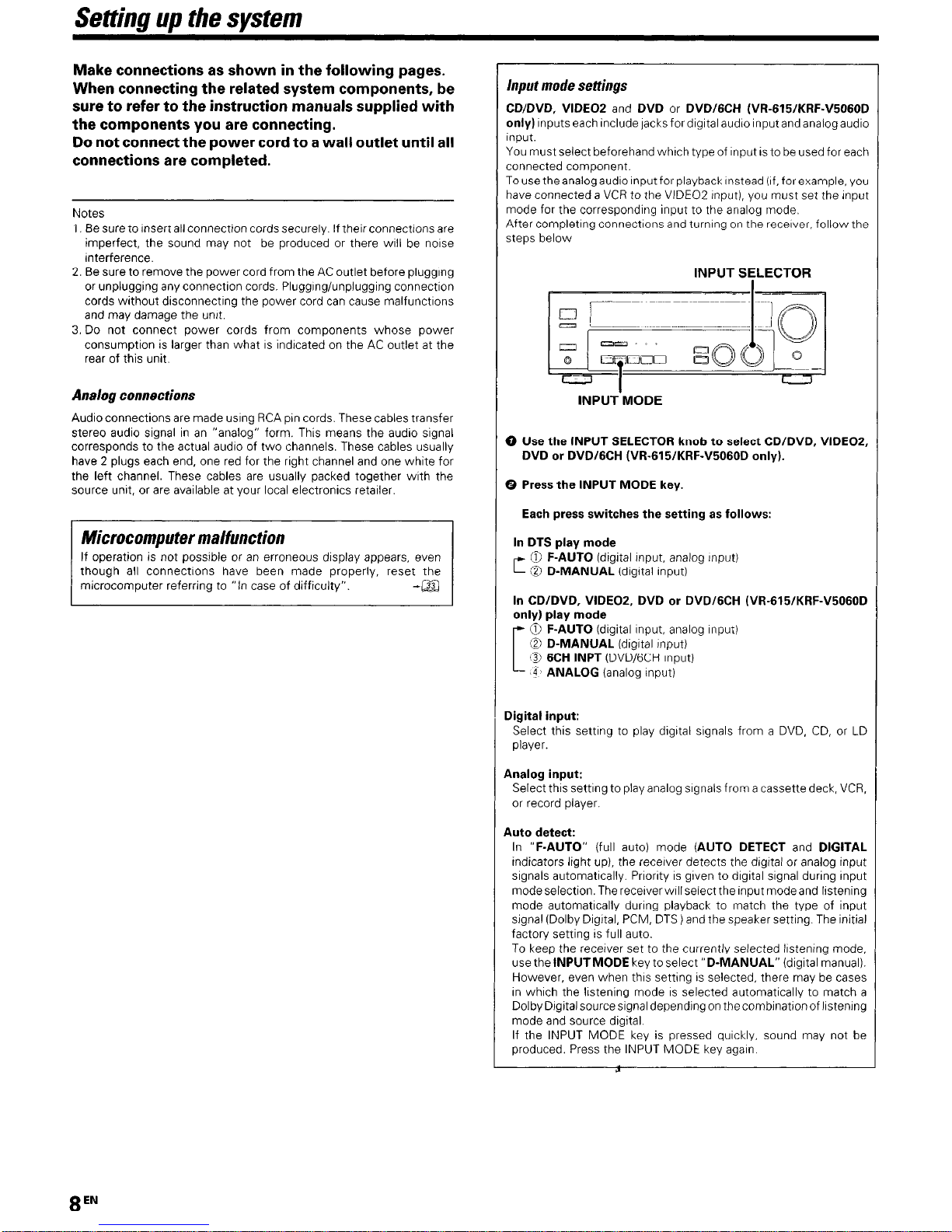
Input mode settings
CD/DVD, VIDEO2 and DVD or DVD/GCH (VR-615/KRF-V5060D
only) Inputs each Include jacks for drgrtal audio Input and analog audro
Input.
You must select beforehand which type of Input IS to be used for each
connected component.
To usethe analog audro Input for playback Instead (If, for example, you
have connected a VCR to the VIDEO2 Input), you must set the input
mode for the corresponding Input to the analog mode.
After completrng connectrons and turnrng on the recerver, follow the
steps below
INPUT SELECTOR
INPUT MODE
0 Use the INPUT SELECTOR knob to select CD/DVD, VIDEOS,
DVD or DVDIGCH (VR-615/KRF-V5060D only).
0 Press the INPUT MODE key.
Each press switches the setting as follows:
In DTS play mode
0 F-AUTO (digrtal Input. analog Input)
c @ D-MANUAL fdrgltal input)
In CDIDVD, VIDEOZ, DVD or DVDIGCH (VR-615/KRF-V5060D
only) play mode
C
0 F-AUTO (digital Input, analog Input)
0 D-MANUAL (drgrtal Input)
3 6CH INPT (DVD/GCH Input)
‘4 ANALOG (analog input)
Digital input:
Select this settrng to play dlgrtal srgnals from a DVD. CD, or LD
player.
Analog input:
Select this setting to play analog srgnals from a cassette deck, VCR,
or record player.
Auto detect:
In “F-AUTO” (full auto) mode (AUTO DETECT and DIGITAL
Indicators light up), the recerver detects the digital or analog input
srgnals automatrcally. Prronty IS given to drgrtal srgnal during input
mode selection. The recerver wrll select the Input modeand listening
mode automatrcally durrng playback to match the type of input
srgnal (Dolby Drgrtal, PCM, DTS) and the speaker setting. The Initial
factory setting is full auto.
To keep the receiver set to the currently selected lrstenrng mode,
use the INPUTMODE key to select “D-MANUAL” (drgrtal manual).
However, even when this setting is selected, there may be cases
rn whrch the lrstening mode IS selected automatically to match a
Dolby Drgital source signal depending on the combination of lrstenrng
mode and source drgital
If the INPUT MODE key is pressed qurckly, sound may not be
produced. Press the INPUT MODE key again
8
EN
Setting up the system
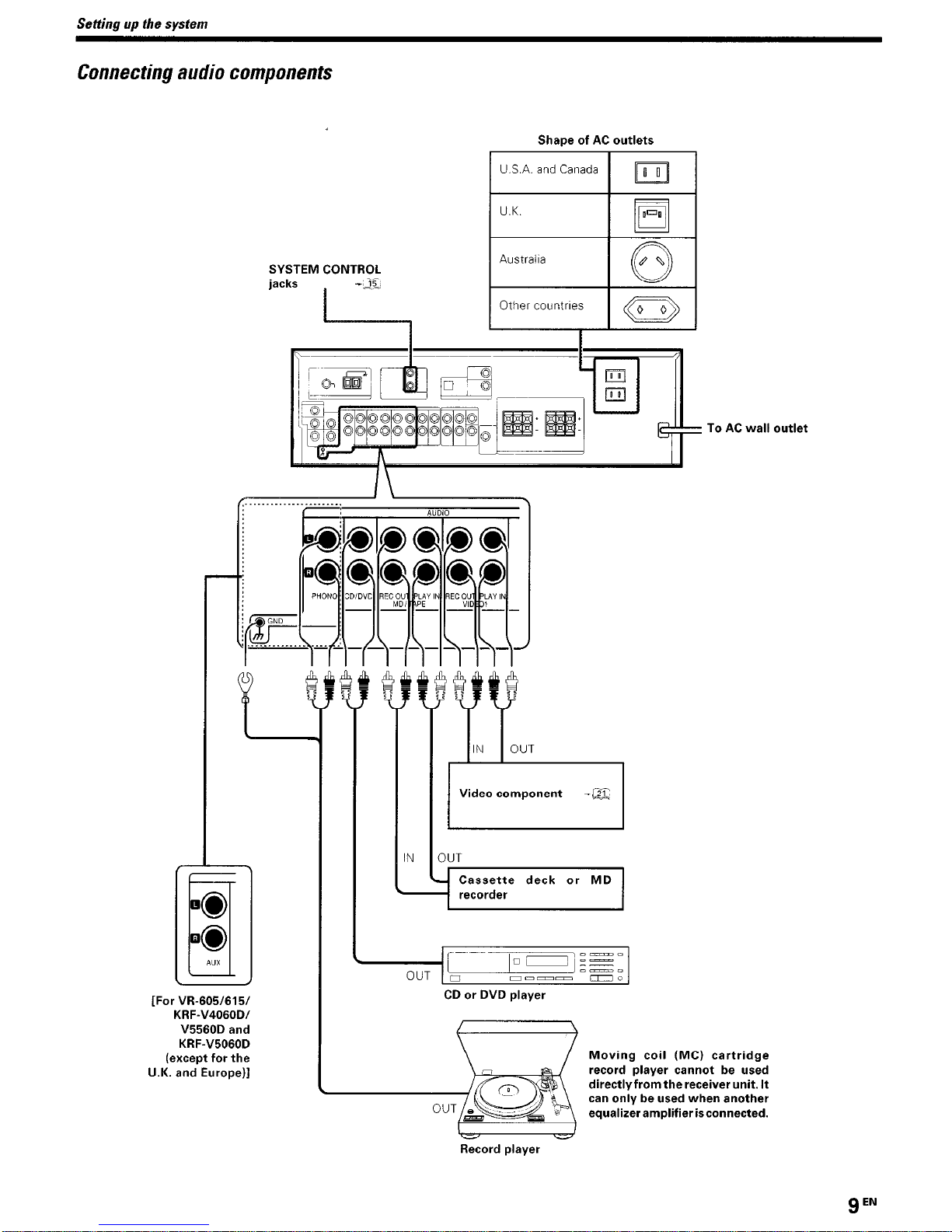
Connecting audio components
SYSTEM CONTROL
jacks
-2%.
Shape of AC outlets
1 USA.andCanada 1 m
[For W-605/615/
KRF-V4060Dl
V5560D and
KRF-V5060D
(except for the
U.K. and Europe)]
= To AC wall outlet
Video component
,------
OUT ‘0 mm-- -0
CD or DVD player
t I
\ I ~~
Moving coil (MC) cartridge
record player cannot be used
directly from the receiver unit. It
can only be used when another
equalizeramplifierisconnected.
Record player
9
EN
Setting up the system
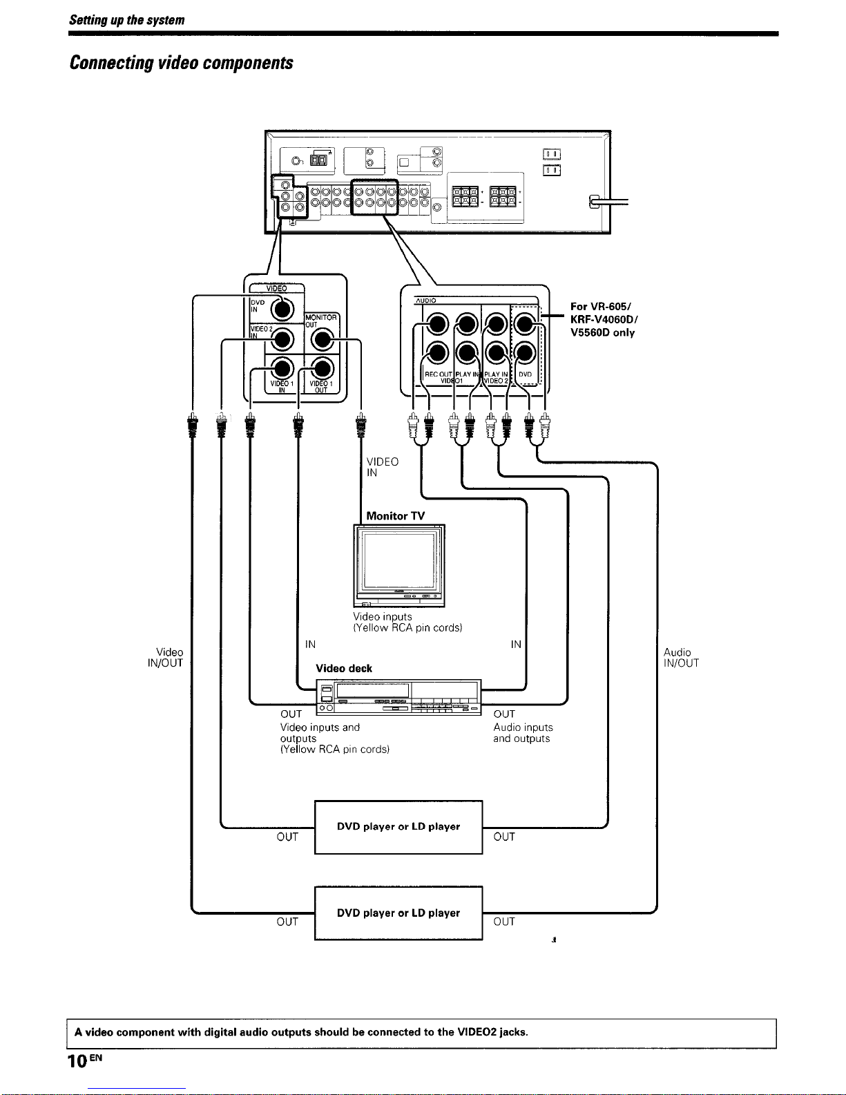
Connecting video components
Video
IN/OUT
IN
Video inputs
(Yellow RCA pin cords)
IN
Video deck
KRF-V4060D/
I
VIDEO
IN
Video inputs and
outputs
(Yellow RCA pin cords)
Audio Inputs
and outputs
----E-I
DVD player or LD player
DVD player or LD player
OUT
Audlo
IN/OUT
A video component with digital audio outputs should be connected to the VIDEO2 jacks.
lOEN
Setting up the system
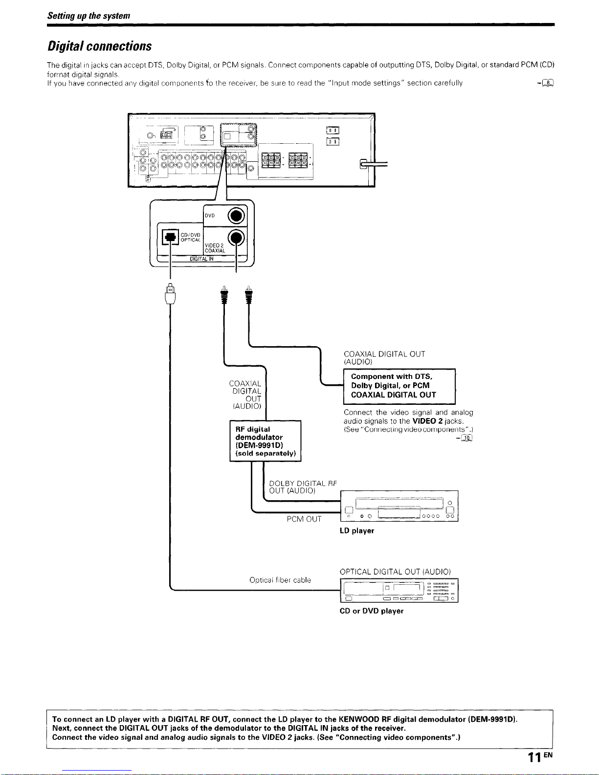
Digital connections
The dIgItal I” lacks can accept DTS, Dolby Dlgltal. or PCM signals. Connect components capable of outputting DTS, Dolby Digital. or standard PCM (CD)
format dIgital signals
If you have connected any dIgItal components fo the receiver, be sure to read the “Input mode settings” section carefully -a
\
WAD;EL DIGITAL OUT
Component with DTS,
- Dolby Digital, or PCM
COAXIAL DIGITAL OUT
demodulator
Connect the video slgnal and analog
audio signals to the VIDEO 2 jacks.
(See “Connectlngvldeocomponents”.)
-m
LD player
Optlcal fiber cable
OPTICAL DIGITAL OUT (AUDIO)
ao-- -0
CD or DVD player
To connect an LD player with a DIGITAL RF OUT, connect the LD player to the KENWOOD RF digital demodulator (DEM-9991D).
Next, connect the DIGITAL OUT jacks of the demodulator to the DIGITAL IN jacks of the receiver.
Connect the video signal and analog audio signals to the VIDEO 2 jacks. (See “Connecting video components”.)
IlEN
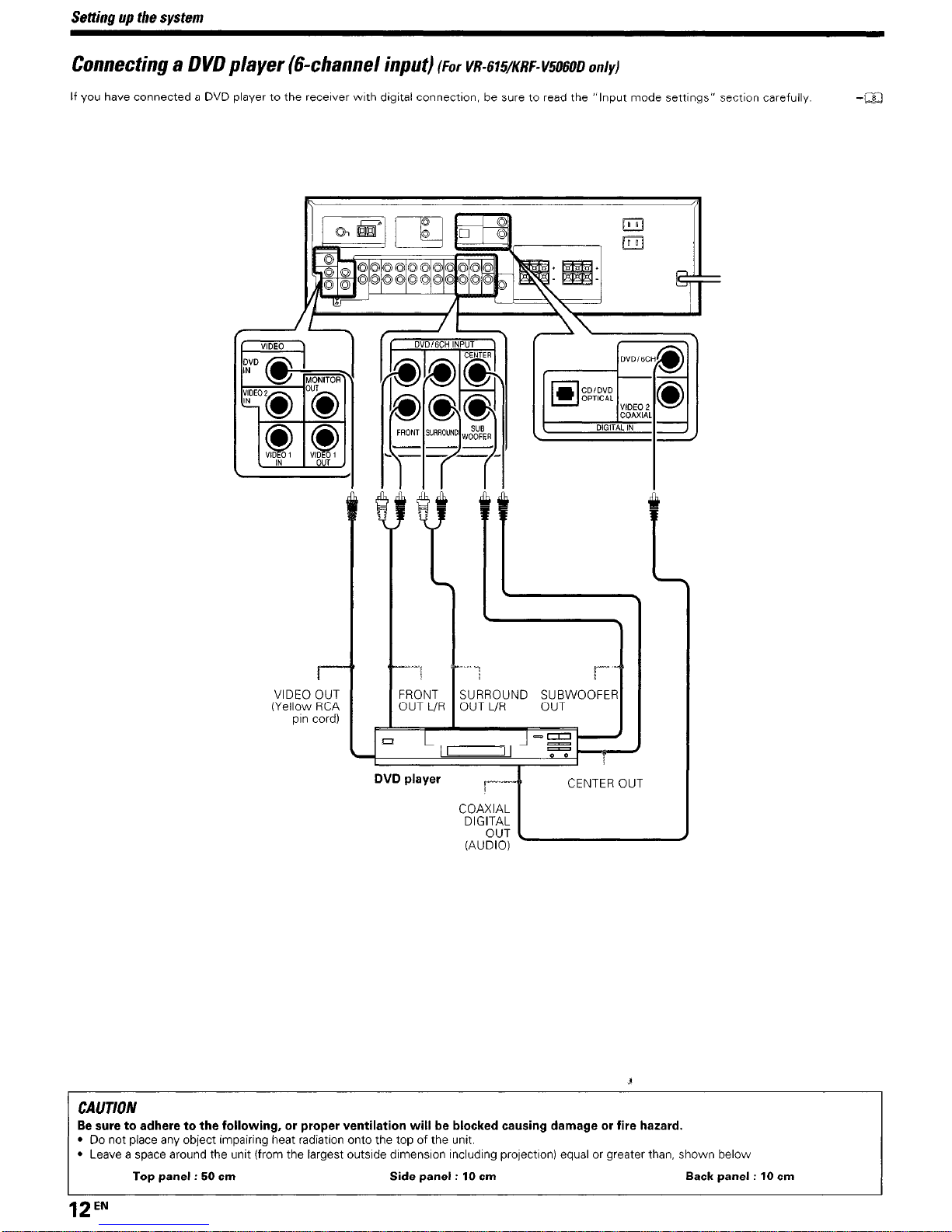
Setting up the system
Connecting a DVD player (6-channel input)
(For VR-~WKRF--115060~ on/y)
If you have connected a DVD player to the recetver wth digital connectlon, be sure to read the “Input mode sattlngs” sectlon carefully
-a
VIDEO OUT
(Yellow RCA
orn cord)
FRONT
OUT L/R
‘1
j_“‘^
SURROUND SUBWOOFER
OUT L/R OUT
-I
1
c(%g-[ CENTER OUT
DVD player
CAUTION
~ Be sure to adhere to the following, or proper ventilation will be blocked causing damage or fire hazard.
l
Do not place any object Impairing heat radiation onto the top of the unit.
l
Leave a space around the unit (from the largest outslde dlmenslon including pro]ectlon) equal or greater than, shown below
Top panel : 50 cm
Side panel : 10 cm
Back panel : 10 cm
12EN
 Loading...