

Kenwood KRF-V5030D, KRF-V6030DE, KRF-V6030D, KRF-V5030DE, KRF-V6030D-S Service Manual
...
AUDIO VIDEO SURROUND RECEIVER
KRF-V4530D
KRF-V5030D/V5030DE/V5030D-S
KRF-V6030D/V6030DE/V6030D-S
VR-405/406/414
SERVICE MANUAL
© 2000-1/B51-5597-00 (K/K) 3493
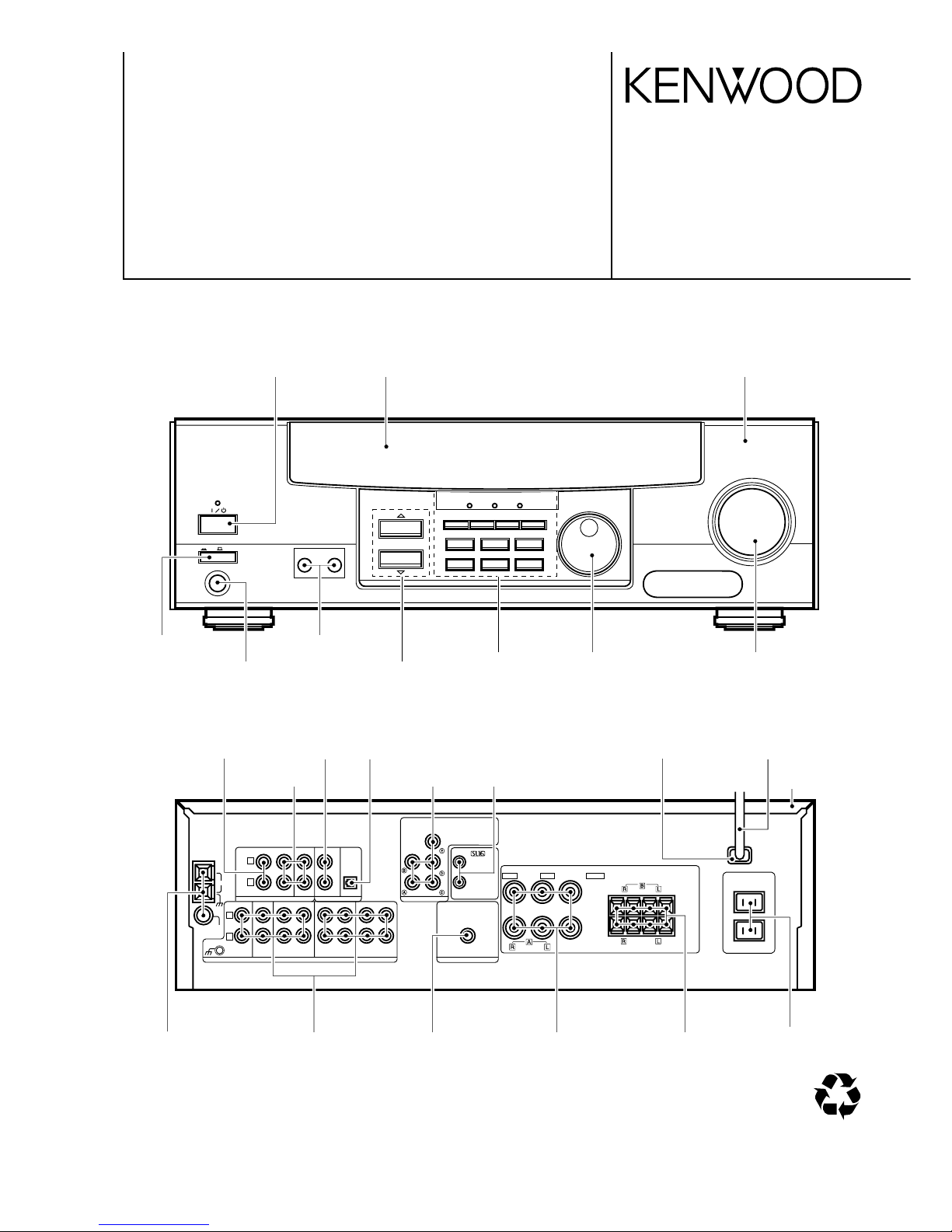
A SPEAKERS B
STANDBY
POWER
LISTEN MODE
SOUND
SOURCE DIRECT
AUTOBAND MEMORY
INPUT SELECTOR
VOLUME CONTROL
UPDOWN
PROLOGIC 3 STEREO
DOLBY
DIGITAL
INPUT MODESET UP DIMMER MONITOR
PHONES
ON/STANDBY
ON OFF
6CHINPUT
FOR EXTRA DIGITAL AUDIO FORMAT
MULTI CONTROL
OPTICAL
DVD
CD/DVD
VIDEO
VIDEO 2
COAXIAL
DIGITAL IN
VIDEO 1
PLAY INREC OUT
SYSTEM CONTROL
—
+
FRONT SPEAKERS
(8 — 16‰)
CENTER SPEAKERS
(8 — 16‰)
SUB WOOFER PRE OUT
—++
—
FRONT SPEAKERS
SURROUND SPEAKERS
AC OUTLET
(8 — 16‰)
(8 — 16‰)
RED
BLUE GREEN
FM
75‰
GND
AM
MONITOR
PLAY IN
PLAY IN
REC OUT
AUDIO
L
R
MD/TAPE1
CD/DVD
PHONO
GND
REC OUT
FRONT
L
CENTER
SURROUND
SUB WOOFER
DVD/6ch INPUT
R
Knob
(K29-7688-03)
Front glass
(B10-3550-02)
Panel
(A60-1757-11)
Knob
(K29-7679-04)
Knob
(K29-7682-14)
Knob
(K29-7676-12)
Knob
(K29-7688-03)
Knob
(K27-2385-04)
Pin jack
(E63-1139-05)
Pin jack
(E63-1080-05)
Miniature phone jack
(E11-0293-05)
Metallic cabinet
(A01-3734-01)
Power cord bushing
(J42-0083-05)
AC power cord
(E30-2942-05)
Lock terminal board
(E20-0321-05)
Pin jack
(E63-1143-05)
Pin jack
(E63-1146-05)
Screw terminal board
(E70-0049-05)
Lock terminal board
(E70-0057-05)
AC outlet
(E03-0149-05)
Illust. is KRF-V6030D-S(M).
70%
Pin jack
(E63-1141-05)
Pin jack
(E63-1138-05)
Optical receiving module
(W02-2716-05)
Knob
(K29-7685-03)
Phone jack
(E11-0272-05)
This manual is divided into four sections, Preparations, Operations,
Other, and Remote Control.
Remote Control (Separate booklet) (VR-407/VR-406/KRFV7030D/KRF-V6030D only)
Includes the “Quick Start Guide,” which shows you how to operate other
components using the remote control, as well as a detailed explanation
of all remote control operations. Once you have registered your components with the proper setup codes, you’ll be able to operate both this
receiver and your other AV components (TV, VCR, DVD player, LD player, CD player, etc.) using the remote control supplied with this receiver.
The manual covers the VR-407, VR-406, VR-405, VR-414, KRFV7030D, KRF-V6030D, KRF-V5030D, and KRF-V4530D. Items such
as functions, number of jacks, and remote control details differ somewhat between these models. To confirm the functions available on the
model you have purchased, refer to the table below.
Model name
Remote
Terminal
Control
Speaker out
VIDEO 3 jacks
Front input
VR-407 RC-R0609 2 systems Equipped Equipped
KRF-V7030D (A, B)
VR-406 RC-R0609 2 systems Not equipped Not equipped
KRF-V6030D (A, B)
VR-405/414 RC-R0509 1 system Not equipped Not equipped
KRF-V5030D/
V4530D
Memory back up function
Please note that the following items will be deleted from the unit's
memory if the power cord is disconnected from the AC outlet for
approximately 3 days.
• Power mode.
• Input selector settings.
• Device preset.
• Picture output.
• Speaker ON/OFF
• Volume level.
• BASS, TREBLE, INPUT level.
• Subwoofer ON/OFF.
• Dimmer level.
• Monitor ON/OFF.
• MD/TAPE settings.
• 6CH/2CH input setting.
• Listen mode setting.
• Speaker settings.
• Input mode setting.
• Midnight mode setting.
• Broadcast band.
• Frequency setting.
• Preset stations.
• Tuning mode.
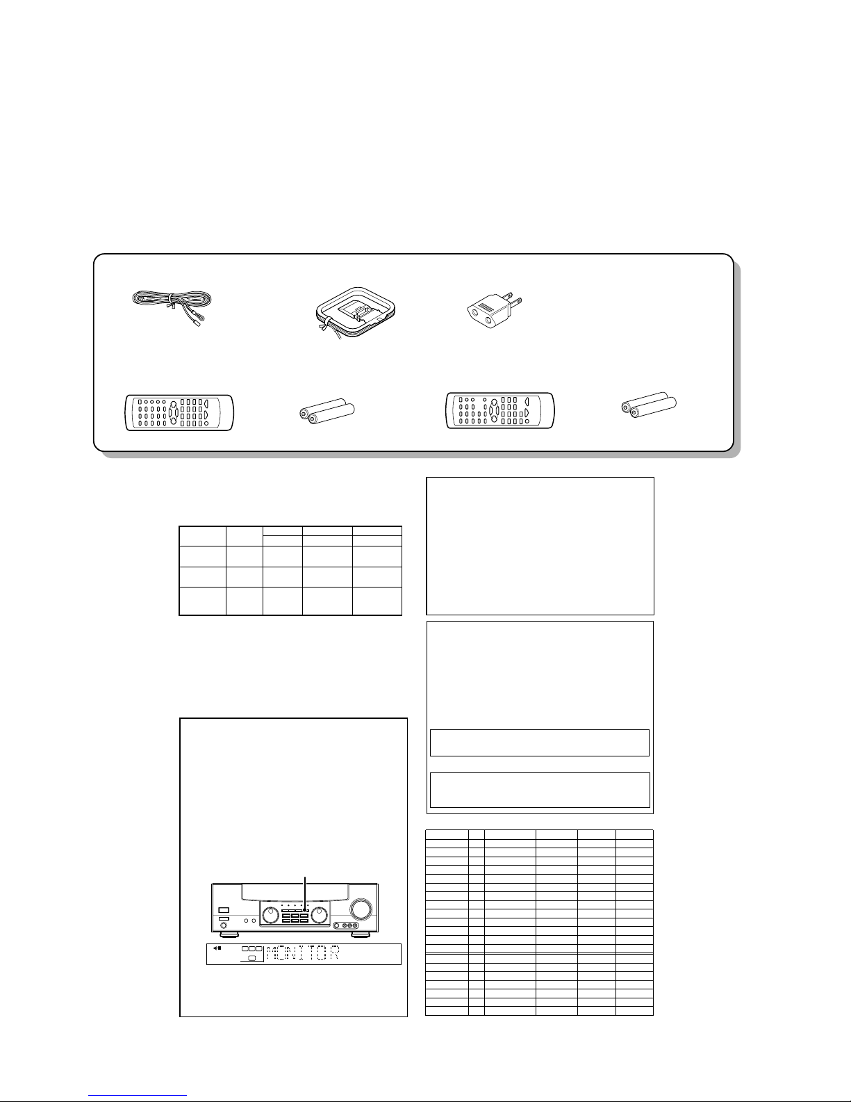
VIDEO 2/MONITOR jacks (for VR-406/405/414/KRFV6030D/V5030D/V4530D)
The receiver’s VIDEO 2/MONITOR jacks can be used in two different
ways. Make the appropriate setting for the component connected to
the jack when the receiver is turned on.
Use as a VIDEO 2 jack
You can connect a video deck or the like to these jacks and perform
video playback and recording. The initial factory setting is “VIDEO 2”.
Use as a MONITOR jack
You can connect a cassette deck or the like to these jacks and make
use of the deck’s monitoring function during recording. Alternately,
you can connect a graphic equalizer to these jacks to apply compensation to the music signal.
To use the VIDEO 2/MONITOR jacks as MONITOR jacks, hold down
the MONITOR key of the main unit for more two seconds so that the
indication shown below appears.
• At the same time the setting is switched to “MONITOR,” the audio
input source switches to tuner and the video input source switches
to VIDEO 1.
• To switch the setting back to “VIDEO 2,” once again hold down the
MONITOR key for two seconds or more.
TUNED
AUTO
FM
MHz
AM
kHz
PRO LOGIC
3
DOWN MIX
DIGITAL
S.DIRECT
DSP
AUTO SOUND
LFE
C
SRSLS
TI.VOLB
CLIP MUTE
RDS EON PTY
TP TA NEWS
STEREO
ST.
MEMO
SW
RL
SP A
MONITOR
MONITOR
Resetting the Microcomputer
If the microcomputer may malfunction (unit cannot be operated,
or shows an erroneous display) if the power cord is unplugged
while the power is ON, or due to some other external factor. If this
happens, execute the following procedure to reset the microcomputer and return the unit to its normal operating condition.
Unplug the power cord from the wall outlet, then plug it
back in while holding down the POWER key.
• Please note that resetting the microcomputer will clear the contents
of the memory and returns the unit to the state it was in when it left
the factory.
With the power cord plugged in, turn the POWER key
OFF. Then, while holding down the ON/STANDBY key,
press POWER.
For U.S.A. and Canada
For other countries
MODEL ABB POWER SUPPLY POWER AMP PREAMP DISPLAY
KRF-V4530D
E4
- X07-3142-71 X08-3010-11 X14-7122-72
KRF-V5030D
E1
-
X07-3142-71 X08-3010-11 X14-7122-72
KRF-V5030D
T5
- X07-3140-51 X08-3010-11 X14-7122-72
KRF-V5030D
Y5
X00-3000-20 X07-3142-91 X08-3010-11 X14-7120-22
KRF-V5030D-S
E3
- X07-3142-71 X08-3010-11 X14-7122-72
KRF-V5030D-S
I5
X00-3000-20 X07-3140-21 X08-3010-11 X14-7120-22
KRF-V5030D-S
M5
X00-3000-20 X07-3140-21 X08-3010-21 X14-7120-22
KRF-V5030D-S
X5
- X07-3140-71 X08-3010-11 X14-7120-72
KRF-V5030DE
E2
- X07-3142-71 X08-3010-11 X14-7122-72
VR-405
K5
- X07-3140-10 X08-3010-10 X14-7120-11
VR-405
P5
- X07-3140-10 X08-3010-10 X14-7120-11
VR-414
K4
- X07-3140-11 X08-3010-10 X14-7120-11
VR-414
P4
-
X07-3140-11 X08-3010-10 X14-7120-11
KRF-V6030D
E6
- X07-3132-72 X08-3010-10 X14-7122-71
KRF-V6030D-S
I6
X00-3000-20 X07-3130-22 X08-3010-10 X14-7120-21
KRF-V6030D-S
M6
X00-3000-20 X07-3130-22 X08-3010-21 X14-7120-21
KRF-V6030D-S
X6
- X07-3130-72 X08-3010-10 X14-7120-71
KRF-V6030DE
E7
- X07-3132-72 X08-3010-10 X14-7122-71
VR-406
K6
- X07-3130-11 X08-3010-10 X14-7120-10
VR-406
P6
- X07-3130-11 X08-3010-10 X14-7120-10
Model vs PCB
KRF-V4530D/V5030D/V6030D/VR-405/406/414
2
CONTENTS / ACCESSORIES /CAUTIONS
CONTENTS / ACCESSORIES / CAUTIONS............. 2
CONTORLS................................................................3
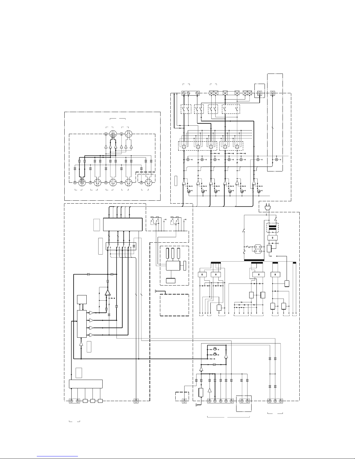
BLOCK DIAGRAM......................................................5
CIRCUIT DESCRIPTION............................................6
ADJUSTMENT............................................................8
SCHEMATIC DIAGRAM.......................................... 17
EXPLODED VIEW ....................................................33
PARTS LIST..............................................................34
SPECIFICATIONS....................................................46
Contents
Cautions
FM indoor antenna (1)
(T90-0836-05)
For VR-406 and KRF-V6030D
For VR-405, VR-414, KRF-V5030D, and KRF-V4530D
Remote control unit (1)
(A70-1330-05): RC-R0609
(A70-1331-05): RC-R0610(E type)
Batteries (R6/AA) (2)
Remote control unit (1)
(A70-1328-05): RC-R0509
(A70-1329-05): RC-R0510(E,T type)
*AC plug adaptor (1)
(E03-0115-05)
*Use to adapt the plug on the power
cord to the shape of the wall outlet.
(Accessory only for regions where
use is necessary.)
Batteries (R6/AA) (2)
AM loop antenna (1)
(T90-0852-05)
Battery cover (A09-1178-08) Battery cover (A09-1178-08)
Accessories
Copy from
instruction
manual.
KRF-V4530D/V5030D/V6030D/VR-405/406/414
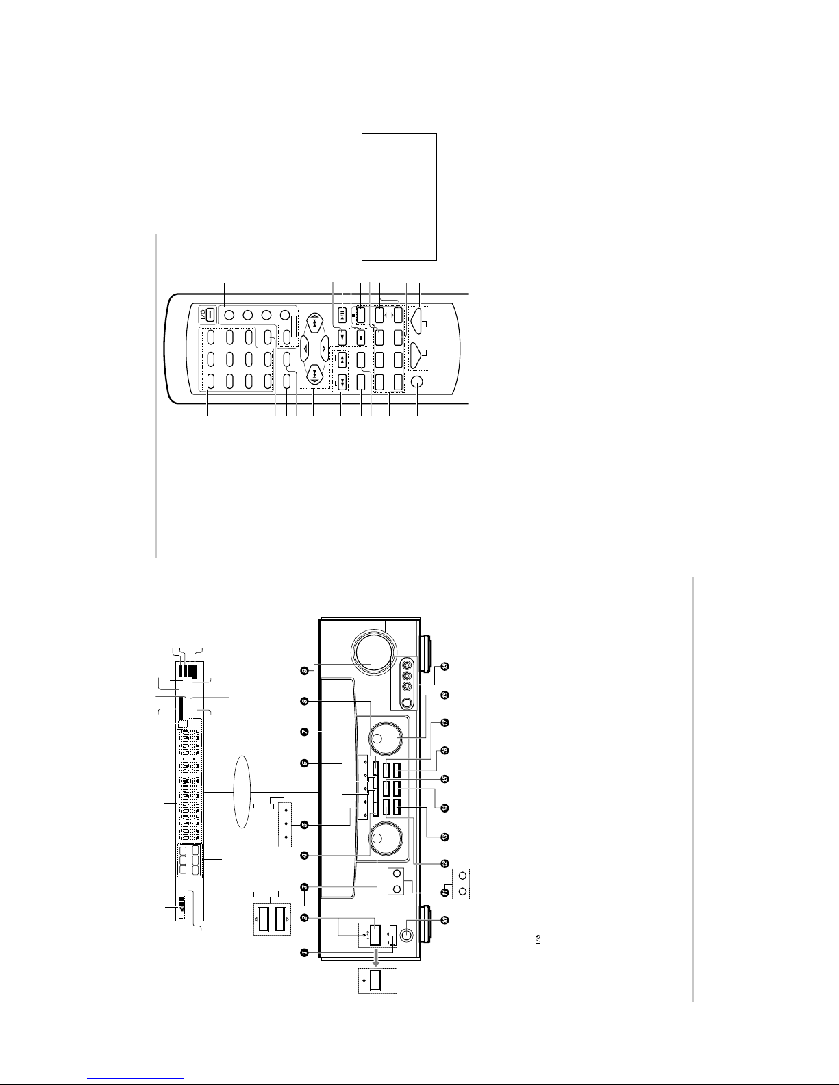
3
CONTROLS
7 B. BOOST key
Use to select the maximum adjustment
setting for the low frequency range.
RECEIVER key
Use to return to the operation of the re-
ceiver.
8 DISC SKIP key
If CD is selected as the input source, this key
functions as the multi-CD player disc skip
key.
A/B key
If TAPE is selected as the input source, this
(A and B) of a double cassette deck.
+100 key
Use to select the disc number with the
multi-CD player.
TITLE key
Use to operate other components.
9 INPUT SELECTOR keys (DVD, PHONO,
CD/DVD, TUNER, MD/TAPE, VIDEO1,
VIDEO2, VIDEO3, AV AUX)
Selects the inputs and sets the remote
control to operate the component regis-
tered at the respective input.
0 MUTE key
Use to temporarily mute the sound.
! POWER key
Use to turn the receiver on and off.
@ POWER key (TV, VCR, DVD, DSS/CDR,
CABLE)
Use to turn the other components on and
off.
# ENTER key
Use to operate other components.
2 key
If tape is selected as the input source, this
key functions as the play key for side B of
the cassette (the side facing away from the
front of the deck).
$ BAND key
Use to select the broadcast band.
6 key
If CD is selected as the input source, this
key functions as the play/pause key.
If MD is selected as the input source, this
key functions as the play key.
% AUTO key
Use to select the auto tuning mode.
7 key
If CD or MD is selected as the input source,
this key functions as the stop key.
^ 8 key
Use to operate other components.
& INPUT SEL. key
Use to operate other components.
* CHANNEL %/fi keys
Use to select the channel.
( TV SEL. key
Use to operate other components.
) VOLUME keys
Use to adjust the receiver volume.
1 Numeric keys
Provide functions identical to those of the
original remote control supplied with the
component you are controlling.
2 LSTN.M key
Use to select the listening mode.
RETURN key
Use to operate other components.
3 SET UP key
Use to select the surround sound settings.
MENU key
Use to operate other components.
4 SOUND key
Use to adjust the sound quality and ambi-
ence effects.
OSD key
Use to operate other components.
5 MULTI CONTROL keys
Used to make a variety of settings.
Use to operate other components.
P.CALL @/# keys
If tuner is selected as the input source,
these keys function as P.CALL keys.
4/¢ keys
If CD or MD is selected as the input source,
these keys function as search keys.
6 TUNING 1/¡ keys
Use to operate the tuner or selected com-
ponent.
There are some cases in which keys (or
knobs) that have the same function on the
receiver and on the remote control have
different names. In the instructions of this
manual, if the names of corresponding
keys (or knobs) on the receiver and remote
control are different, the name of the re-
mote control key is indicated in parenthe-
ses.
Remote control unit (RC-R0609) (VR-407/406/KRF-V7030D/V6030D)
1
B.BOOST
DISC SKIP
DVD
PHONO
CD/DVD
TUNER
MD/TAPE
VIDEO1 VIDEO2 VIDEO3 AV AUX
23
POWER
POWER
TV
VCR
DVD
CABLE
DSS/CDR
RETURN
OSDMENU
P.CALL
TUNING
MUTE VOLUME
A/B+100
TITLE
RECEIVER
AUTO
INPUT SEL.
TV SEL.
CHANNEL
ENTER
BAND
P.CALL
MULTI CONTROL
456
789
0 +10
LSTN.M
SET UP SOUND
1
798
0
243
5
6
!
@
^
*
)
$#%
&
(
CDR
CD
CLIP
DSP
TI.VOL
TP
RDS EON PTY
TA NEWS
FMAMMHz
kHz
PRO LOGIC
3 STEREO
DOWN MIX
DIGITAL
S.DIRECT
MONITOR
MEMO
ST.
TUNED
AUTO SOUND
AUTO
SP
LFE SW
C
AB
MUTE
S RSLS
RL
A SPEAKERS B
STANDBY
POWER
MULTI CONTROL
MULTI CONTROL
LISTEN MODE
SOUND
SOURCE DIRECT
AUTOBAND MEMORY
INPUT SELECTOR
VOLUME CONTROL
UPDOWN
PROLOGIC 3 STEREO DOWN MIX
DOLBY
DIGITAL
DTS
INPUT MODESET UP
S-VIDEO V L – AUDIO – R
AV AUX
DIMMER MONITOR
PHONES
ON/STANDBY
ON OFF
STANDBY
POWER
ON/STANDBY
PROLOGIC 3 STEREO
DOLBY
DIGITAL
SPEAKER MUTE
Display
Speaker selection indicators
Input channel indicators
Output channel indicators
Band indicators
AUTO indicator
MEMO. indicator
ST. indicator
TUNED indicator
3 STEREO indicator
STEREO indicator
Frequency display,
Input display,
Preset channel display,
Surround mode display
Speaker indicator
PRO LOGIC
indicator
S.DIRECT indicator
MONITOR indicator
DOWN MIX indicator
For U.S.A.
and Canada
MUTE indicator
AUTO SOUND indicator
DIGITAL indicator
For VR-407, KRF-V7030D
1 POWER key
(Except for U.S.A. and Canada)
Use to turn the main power ON/OFF.
2 POWER key
(For U.S.A. and Canada)
Use to turn the power ON/OFF.
STANDBY indicator
2 ON/STANDBY (
) key
(Except for U.S.A. and Canada)
Use to switch the power ON/STANDBY when
the POWER is turned ON.
STANDBY indicator
3 MULTI CONTROL knob
(For VR-407/KRF-V7030D)
Used to make a variety of settings.
3 MULTI CONTROL keys
(For VR-406/405/414/KRF-V6030D/V5030D/
V4530D)
Used to make a variety of settings.
4 SET UP key
Use to select the surround sound settings.
5 Surround indicators
÷ DTS indicator
(For VR-407/KRF-V7030D)
Lights when the receiver is in the DTS mode.
÷ DOLBY DIGITAL indicator
Lights when the receiver is in the Dolby
Digital mode.
÷ PROLOGIC indicator
Lights when the receiver is in the
PROLOGIC mode.
÷ 3 STEREO indicator
Lights when the receiver is in the 3 STE-
REO mode.
÷ DOWN MIX indicator
(For VR-407/KRF-V7030D)
Lights when the receiver is in the DOWN
MIX mode.
6 INPUT MODE key
Use to switch between the digital and analog
inputs.
7 DIMMER key
Use to adjust the brightness of the display.
Use to select the REC MODE.
8 MONITOR key
Use to monitor the source that is connected to
the MONITOR jack.
9 VOLUME CONTROL knob
0 PHONES jack
Use for headphone listening.
! SPEAKERS A/B keys
(For VR-407/406/KRF-V7030D/V6030D)
Use to turn the A/B speakers ON/OFF.
! SPEAKER key
(For VR-405/414/KRF-V5030D/V4530D)
Use to turn the speaker ON/OFF.
MUTE key
(For VR-405/414/KRF-V5030D/V4530D)
Use to temporarily mute the sound.
@ SOUND key
Use to adjust the sound quality and ambience
effects.
# BAND key
Use to select the broadcast band.
$ AUTO key
Use to select the auto tuning mode.
% LISTEN MODE key
Use to select the listening mode.
^ MEMORY key
Use to store radio stations in the preset
memory.
& SOURCE DIRECT key
Use to pass the source material direct to the
amplifier.
* INPUT SELECTOR knob
Use to select the input sources.
( AUX IN S VIDEO/VIDEO/AUDIO L/R
jacks
(For VR-407/KRF-V7030D)
Standby mode
While the standby indicator of the unit is lit, a small amount of current is flowing into the unit’s internal circuitry to back up the memory. This condition is referred
to as the standby mode of the unit. While the unit is in the standby mode, it can be turned ON from the remote control unit.
For VR-405, VR-414,
KRF-V5030D,
KRF-V4530D
For VR-406, VR-405, VR-414
KRF-V6030D, KRF-V5030D,
KRF-V4530D
KRF-V4530D/V5030D/V6030D/VR-405/406/414
4
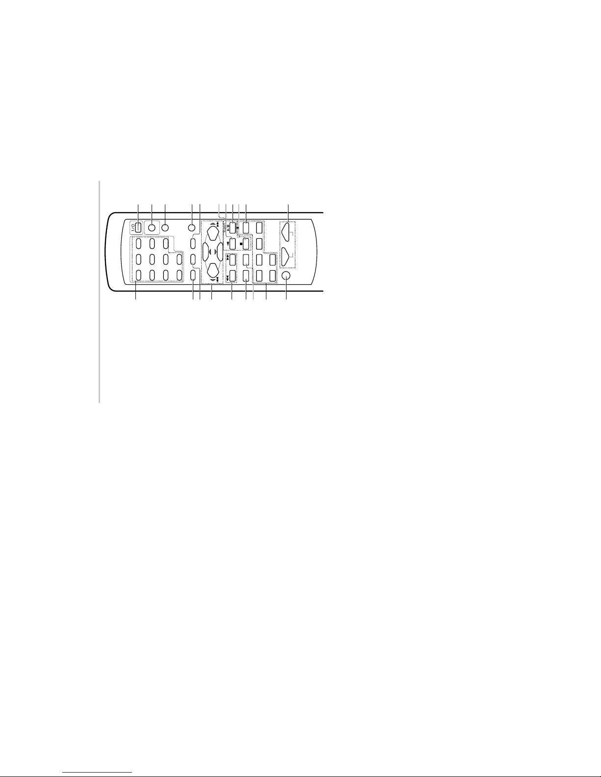
CONTROLS
Remote control unit (RC-R0509) (VR-405/414/KRF-V5030D/V4530D)
7 DISC SKIP key
If CD is selected as the input source, this key
functions as the multi-CD player disc skip
key.
A/B key
If TAPE is selected as the input source, this
(A and B) of a double cassette deck.
+100 key
Use to select the disc number with the
multi-CD player.
8 INPUT SELECTOR keys (DVD, PHONO/
AUX, CD/DVD, TUNER, MD/TAPE,
VIDEO1, VIDEO2)
Selects the inputs and sets the remote
control to operate the component regis-
tered at the respective input.
9 MUTE key
Use to temporarily mute the sound.
0 POWER key
Use to turn the receiver on and off.
! DVD key
Used to operate DVD player.
For details, refer to the instruction manual
of your DVD player.
@ RECEIVER key
Use to return to the operation of the re-
ceiver.
# TITLE key
Use to operate other components.
$ LISTEN MODE key
Use to select the listening mode.
1 Numeric keys
If CD or MD is selected as the input source,
these keys function as numeric keys. If
tuner is selected as the input source, these
keys are used to call up station presets.
2 SET UP key
Use to select the surround sound settings.
MENU key
Use to operate other components.
3 SOUND key
Use to adjust the sound quality and ambi-
ence effects.
OSD key
Use to operate other components.
4 MULTI CONTROL keys
Used to make a variety of settings.
P.CALL @/# keys
If tuner is selected as the input source,
these keys function as P.CALL keys.
4/¢ keys
If CD or MD is selected as the input source,
these keys function as search keys.
5 TUNING 1/¡ keys
If tuner is selected as the input source,
these keys function as tuning keys.
6 BASS BOOST key
Use to select the maximum adjustment
setting for the low frequency range.
RETURN key
Use to operate other components.
% Component operation keys
Use these keys to operate other components
with system control connections to the re-
ceiver.
2 key
If tape is selected as the input source, this
key functions as the play key for side B of the
cassette (the side facing away from the front
of the deck).
6 key
If CD is selected as the input source, this key
functions as the play/pause key.
If MD is selected as the input source, this key
functions as the play key.
7 key
If CD or MD is selected as the input source,
this key functions as the stop key.
^ ENTER key
Use to operate other components.
& BAND key
If tuner is selected as the input source, this
key functions as the band selector key.
* AUTO key
If tuner is selected as the input source, this
key functions as the AUTO key.
( 8 key
Use to operate other components.
) VOLUME keys
Use to adjust the receiver volume.
1
DISC SKIP
BASS BOOST
AUTO
PHONO/AUX
CD/DVD
TUNER
MD/TAPE
VIDEO1 VIDEO2
23
POWER
DVD
POWER
RECEIVER
MENU
P.CALL
TUNING
MUTE
VOLUME
A/B+100
DVD
ENTER
BAND
P.CALL
MULTI CONTROL
456
789
0 +10
SET UP
OSD
SOUND
RETURN
TITLE
LISTEN MODE
1
687
9
324
5
0
!
@
#
$
()&
^%*
KRF-V4530D/V5030D/V6030D/VR-405/406/414
5
BLOCK DIAGRAM
LINE BUF
PHONO EQ
TUNER
AK4527
LPFLPF LPF LPF
x2x2 x2 x1
M62446SP
6ch E. VOL
with 2ch
TONE CONT.
x0.5
BUF
IC113
+20/0dB
+B HITAP
-B HITAP
+B LOWTAP
-B LOWTAP
VIDEO2
(VIDEO2/MONI.)
OPTICAL
VIDEO3
VIDEO3
VIDEO2
VIDEO1
CD
PHONO
MD
/TAPE
MONI
PLAY
REC
OUT
Lch
H, P, Rch
H, P, Lch
Rch
Cch
Lch
Rch
LSch
RSch
SWch
SP-B
SP-A
AC IN
+5V
A.V.R
for
u-COM
+15V
A.V.R
A.V.R
-15V
+5V
+7V
-7V
A.V.R
5V
for E. VOL
u-COM
for FIL AC
(AUDIO & VISUAL)
TUNER etc.
for AMP (HI TAP)
for AMP (LOW TAP)
for RELAY SW
A2
J2
IC601,602
SWITCHED
D101
D103
D41
IC103
IC104
-30V
Q54
IC51IC2
IC15
Q7
Q8
Q13
Q1
Q2
Q14
Q11
Q12
Q17
Q5
Q6
IC114
for INPUT SEL.
CIRCUIT
(1/2)
(2/2)
(1/2)
(1/2)
(2/2)
(2/2)
IC111
IC111
IC112
IC110
IC110
IC112
6ch INPUT
DVD
SUB
#S5
#S2
DIG
#S4
R,L
MIX
#S3
LS,RS
#S7
NOSUB
ANA
#S1
REC OUT BUF.
IC107
ANALOG REC
DIGITAL REC
D102
A.V.R
for
DIR etc.
A.V.R
3.3V
IC46
MUTE
J75
DSP
Lch
Rch
Cch
LSch
RSch
SWch
IC45
for DSP
A.V.R
5V
J1
J1
K1
K2
K3
K4
J2
PRE OUT
(L,R,C,LS,RS,1SW)
LSch
RSch
J2
J6
J7
IC101 or
IC102 or
10,15,16
Q3,4,9
CODEC
(ADC&DAC)
AK4110
IC5
A1
A3
OPTICAL
CD/DVD
MONI.
OPTICAL
COXIAL
COXIAL
OUT
DIGITAL
IN
AUDIO
DIGITAL
RECEIVER
6ch INPUT
DVD
AUDIO IN/OUT
20dB AMP
IC105
(VIDEO2/
MONI.)
VIDEO1
/MD
TAPE
(VIDEO2
/MONI.)
MONI.
FRONT AUX
J2
/12dB ATT
6dB/9dB
IC14
(NOT for K,P TYPE)
VIDEO1
VIDEO2
VIDEO3
6ch INPUT
VIDEO1
MONITOR
DVD
INPUT
FRONT
J66
J65
REC OUT
J71
TACT KEY
MAIN
u-COM
IC1
RDS
IC4
LED
ENCODER
FL
BU1923F
11-MT-120GK
ED1
IR REPEATER
SYNC
RF REMOCON
RECEIVER UNIT
DIR
J5
for DSP. AD/DA.
ANALOG 6ch
INPUT SELECTOR
VISUAL IN/OUT
LFE
DA
AD
2
BYPASS
SW
C
LS,RS
L, R
L, R
L
R
C
LS
RS
SW
C LS/RS L/R
+
+
+
+
+
+
+
4700uF
4700uF
3300uF
470uF
2200uF
3300uF
2200uF
+
2
5
IC2
6
2
(X07)
(X08)
VR-405/414/406/407/407-S/409
KRF-V3030D
EXCEPT for
USED
EXCEPT for
VR-405/406/414
KRF-V4530D/V5030D/V5030D-S/V5030DE
(X14)
USED VR-407/407-S/409/KRF-V7030D/V7030D-S/V8030D/V8030D-S/V3030D
(X14)
KRF-V6030D/V6030D-S/V6030DE
KRF-V3030D/V4530D/V5030D/V5030D-S/V5030DE
KRF-V6030D/V6030D-S/V6030DE
KRF-V7030D/V7030D-S/V8030D/V8030D-S
KRF-V8030D
KRF-V8030D-S
KRF-V8030D-S
KRF-V8030D
KRF-V3030D
(X08)

KRF-V4530D/V5030D/V6030D/VR-405/406/414
6
CIRCUIT DESCRIPTION
Pin No. Pin Name I/O Description
1 S. DATA I/O Serial data signal.
2 S.BUS I/O Serial busy signal.
3 SEL. ST1 O Strobe output to input selector ( IC106).
4 SEL/VOL/PLL DT O Data output to selector,volume and PLL IC.
5 SEL/VOL/PLL CLK O Clock output to selector,volume and PLL IC.
6 SEL. ST2 O Strobe 2 output to input selector ( IC109).
7 PLL. CE O PLL chip enable.
8 Vdd (+5v) - Power supply.
9 OSC OUT O 8MHz clock output.
10 OSC IN I 8MHz clock input.
11 Vss - Connected to ground.
12 X IN - Connected to ground.
13 X OUT - No used.
14 MMCD - Connected to ground.
15 Vref- - Connected to ground.
16,17 KEY2,KEY1 I Input terminal of key1 and key2.
18 MODEL TYPE I Discrimination port of models.
19 TH. SENS I No used.
20 PROTECT I Detection port of protection signal 1.
21 PROTECT2 I Detection port of protection signal 2.
22 S.LEVEL/CH SPACE I RDS S level and channel space changeover.
23 PLL DO I RDS PLL data signal input.
24 Vref+ - Reference voltage of AD converter..
25 CE I Chip enable.
26 RESET I Reset signal input.
27 T. MUTE O Muting signal output to tuner.
28 RF ST O CE signal output of RF receiver IC.
29 RF DT O Data signal output of RF receiver IC.
30 RF CLK O Clock signal output of RF receiver IC.
31 VOL.ST O Latch output of electric volume.
32 DSP INTREQ I/O Detection port of DSP INTREQ.
33 DTS DET I Detection port of DTS data.
34 REMOCON I Remote control signal input.
35 DIR ERR I Detection port of DIR error signal.
36 DZF I Detection port of CODEC zero input.
37 RDS.CLK I RDS clock input.
38 RDS.DAT/CE2 I RDS data input./u-COM chip enable 2.
39 DSP/DIR/CORDEC CDIN O Serial data output.
40 DSP/DIR/CDOUT I Serial data input.
41 DSP/DIR/CORDEC CCLK O Clock output to IC2, IC5 and IC51on X08.
42 DSP CS O DSP chip select.
43 DSP PD O DSP power down.
44 DIR CODEC CS O CODEC chip select.
45 DIR CODEC PD O DIR CODEC power down.
46 NO USE - No used.
47-57 1G-11G O FL grid control(1G-11G).
58-74 P1-P17 O FL segment control(P1-P17).
75 PACK CONT. O Power pack control.
76 LIMMITER O Control port of A class power supply.
77 REAR RE O Relay control terminal of surround speaker.
78 CENTER RE O Relay control terminal of center speaker.
79 FB RE O Relay control terminal of front B speaker.
80 FA RE O Relay control terminal of front A speaker.
Pin description of microprocessor : X14,IC1(MN101C35DRA)

KRF-V4530D/V5030D/V6030D/VR-405/406/414
7
CIRCUIT DESCRIPTION
Pin No. Pin Name I/O Description
81 POWER RE O Power relay control.
82 CS5. 1(DOWN MIX)LED O Control terminal of CS5.1(DOWN MIX) LED.
83 3 STEREO LED O Control terminal of 3 STEREO LED.
84 DTS LED O Control terminal of DTS LED.
85 DOLBY DIGITAL LED O Control terminal of DOLBY DIGITAL LED.
86 PROLOGIC LED O Control terminal of PROLOGIC LED.
87 STANDBY LED O Control terminal of STANDBY LED.
88 PRE OUT MUTE O Muting control terminal of pre out.
89 20dB ATT O 20dB attenuation(volume) control terminal.
90 A.MUTE O Audio muting signal output.
91 ABOOT O EPROM CS.
92 MULTI. ENC CW I Multi cont. encoder signal input(clockwise).
93 MULTI. ENC CCW I Multi cont. encoder signal input(counterclockwise).
94 SEL. ENC CW I Selector encoder signal input(clockwise).
95 SEL. ENC CCW I Selector encoder signal input(counterclockwise).
96 VOL. ENC CW I Volume encoder signal input(clockwise).
97 VOL. ENC CCW I Volume encoder signal input(counterclockwise).
98 STEREO I Stereo (tuner) signal input.
99 SD I Tuner (SD)detector input.
100 Vpp(-30V) - FL power supply(-35V).
KRF-V4530D/V5030D/V6030D/VR-405/406/414
8
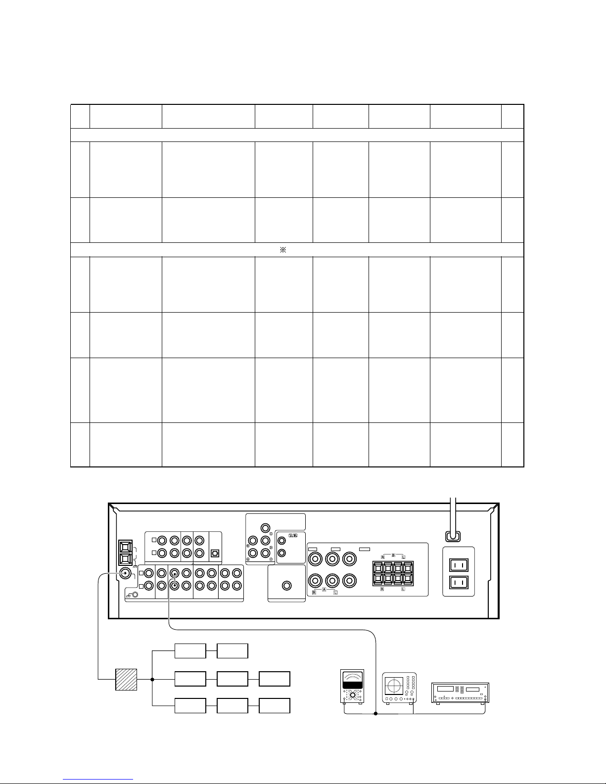
ADJUSTMENT
No. ITEM INPUT SETTINGS
OUTPUT
SETTINGS
RECEIVER
SETTINGS
ALIGNMENT
POINTS
ALIGN FOR
FIG.
1
(A)
98.0MHz 1kHz,
±75kHz dev.
70dBf (ANT. input)
98.0MHz
2 TUNING LEVEL
(A)
98.0MHz MONO 1kHz,
±75kHz dev.
29.2dBf (ANT. input)
(B)
MONO
98.0MHz
VR1
(X07)
Adjust VR1 and
stop at the point
where ED1
(TUNED) goes on.
1 DISCRIMINATOR
DISCRIMINATOR
(A)
98.0MHz 1kHz,
±40kHz dev.
Connect a DC
voltmeter
between CN4
1 and CN4 2
(X07)
Connect a DC
voltmeter
between CN4
1 and CN4 2
(X07)
MONO
98.0MHz
L4
(X07)
L4
(X07)
0V
0V
3
DISTORTION
(STEREO)
98.0MHz
(C)
1kHz, ±40kHz dev.
Selector : L or R
Pilot : ±6kHz dev.
70dBf (ANT. input)
(B)
AUTO
98.0MHz
IFT
(FRONT END
: A1)
Minimum distortion
(L or R)
2
DISTORTION
(MONO)
(A)
98.0MHz 1kHz,
±40kHz dev. MONO
70dBf (ANT. input)
(B)
MONO
98.0MHz
L5
(X07)
Minimum distortion
4 TUNING LEVEL
(A)
98.0MHz MONO 1kHz,
±40kHz dev.
29.2dBf (ANT. input)
(B)
MONO
98.0MHz
VR1
(X07)
Adjust VR1 and
stop at the point
where ED1
(TUNED) goes on.
FM SECTION : EXCEPT E,T type SELECTOR : FM
FM SECTION : E,T type only SELECTOR : FM Adjust NO.1 and NO.2 repeat.
70dBf (ANT. input)
(K,P only)
OPTICAL
DVD
CD/DVD
VIDEO
VIDEO 2
COAXIAL
DIGITAL IN
VIDEO 1
PLAY INREC OUT
SYSTEM CONTROL
—
+
FRONT SPEAKERS
(8 — 16‰)
CENTER SPEAKERS
(8 — 16‰)
SUB WOOFER PRE OUT
—++
—
FRONT SPEAKERS
SURROUND SPEAKERS
AC OUTLET
(8 — 16‰)
(8 — 16‰)
RED
BLUE GREEN
FM
75‰
GND
AM
MONITOR
PLAY IN
PLAY IN
REC OUT
AUDIO
L
R
MD/TAPE1
CD/DVD
PHONO
GND
REC OUT
FRONT
L
CENTER
SURROUND
SUB WOOFER
DVD/6ch INPUT
R
(A)
(B)
(C)
FM SG
FM SG
TV SG
AG
MPX
HTB
TV MPX
AG
AG
AC voltmeter
Oscilloscope
Distortion meter
Dummy antenna
(D)
SYSTEM CONNECTIONS
KRF-V4530D/V5030D/V6030D/VR-405/406/414
9
PARTS DESCRIPTIONS
A BDFHJCEGI
2
1
3
5
7
4
6
Y05-4050-10
KRF-V4530D/V5030D/V6030D/VR-405/406/414
GND
GND
ANT2
ANT1
4
3
2
1
100
100
R12
680K
R11
100K-
680-2.2K
R6
8P
0-8P
2-6P
C20
150P
R9
L6
C12
R10
10K
C15
27P
27P
C14
C16
3.9K
C13
R8
10K
R7
C17
100P
8OUT
IF-OUT 7
C10
33K
L3
0-100
100K
C1 0-8P
C18
180P
L1
L2
10P
R1
C2
C6 4P
C3 0-8P
1.2M
470K-
1000P
180P
0.1
C9
68
R14
C19
C5
R5
L5
L4
3P
R13
680
C7
27P
R3
R2 C4
R4
33K
0.1
+B 6
VT
IFT
C8
0.1
5
OSC
100
R4
R2
33K
0-5P
GND4
ANT1
GND
GND3
2
1
C3
27P
L1
C1
27P
C2
15P
C14
0.1
C5
3-7P
R1
100K
R3
100K
L2
C4
10P
C6
R6 33K
C7 5-10P
L3
L4
0-100
R15
10K
1.5K
C21
10P
R17
470-
C16
47P
7C9
C15
3.9K
2-6P
C17
L7
R12
C19
C20
8P
27P
R14
10K
R16
220
R18
C8 0-6P
R7 33K
R5
1000P
L5
C10
L6
5P
C12 2P
680K-1.5M
R8
680
R9
C11
27P
0.1
C22
1-3P
100
R19
150K-
560K
C23
OSC
100P
0-100
VCC
8
6
R11
IF-OUT
IFT
VT
0.1
C13
5
270
R44
100
0.01C3R8
R2
220
C2
0.01
3.3K
R7
820
680
R4
CF1
CF2
R12
100
1/4W
3P
C75
R41 100K
L1
R42 10K
1uH
L2
S-METER
DRIVE
TUNING
FM
AM/FM
S-CURVE
1
2
FM IF
S-METER
FM
DET
IF-BUFF
3
4
GND
5
AM
OSC
BUFF
ALC
30
29
SD
COMP
AM
AM IF
RF.AMP
AM
MIX
REG
28
AM
AGC
27
26
VCC
8
6
7
DRIVE
STEREO
9
12
10
11
13
15
14
MUTE
DET
25
24
23
22
38K
304KHz
VCO
FF
2
19K
FF
DECODER
ANTI-BIRDIE
P-DET
21
SW
STEREO
20
19
PILOT
DET
FF
19K 8
18
17
16
47P
0.047
C20
10u10
C19
+
0.047
C22
3.3u35
C21
+
R25 C26330P
10u16
C23
+
4.7u25
C27
C25
VR1
10K
R27
R28
2.2u50
C29
+
2.2u50
C28
+
C31
C79
C30
C80
10u16
C38
+
10u16
C37
+
0.01
C34
C33
0.01
560
R30
47K
R31
0.047
C1222R16
R14
CF3
10u16
C14
+
R17 3.6K
C45 22P
+
C15
1u50
3.9K
3K
R18
0.47u50
C16
+
R19
C17
1u50
+
8.2K
L4
1
C81
L3
0.047
C11
47u16
C10
+
21
R23
R83 1K
47P
C76
C41
47P
21
C B I/F
DIVIDER
REFERENCE
3
2
1
4
5
2
22
14
SWALLOW COUNTER
1/16,1/17 4bits
ON
DETECTOR
RESET
DATA SHIFT REGISTER LATCH
6
7
8
10
9
11
POWER
CHARGE PUMP
PHASE DETECTOR
UNLOCK
20
19
18
17
16
UNIVERSAL COUNTER
12bits PROGRAMABLE
DIVIDER
1/2
15
13
12
7.2MHz
X1
C42
10P
1.2K
R59
R58 12K
10K
R48 1K
R47 1K
R46 1K
R45 1K470P
C44
47u16
C48
+
10u16
C46
+
1000P
2.2u50
+
0.022
R531K
R54
R51
5.6K
100
R52
470
R50
C47
1/4W
1K
R56
100P
C521KR57
470P
C51
100P
C50
33K
R55
R43
220
VCC
2
1
4
3
E1
C1
0.022
C18
L5
15
14
13
12
11
10
9
8
7
654
3
2
1
DET
S-LEVEL
SD
STEREORGNDL+12V
-12V
T. MUTE
PLL DT
PLL CLK
PLL CE
PLL DO
CH.SPACE
R82 2.7K
1u50
C72
+
47u16
C73
+
R1
R5
R6 220
0.01
C5
R11
C6
0.01
390
R9
1K
R10
0.01
R81
0.01
82 1W
R80 22K
4.7u35
C32
+
R40
10K
1K
R38
R39
1K
L6
W682
6800P
C70
L7
C71
6800P
W683
820
8.2K
R75
1K
1.8K
R76
R78
R77
47K
R74
C83
100P
W656
6
3
5
4
3
5
4
6
R84
1K
1K
R72R73
C78
C49
2.2K
4700P
4700P
C24
R85
1M
1M
R86
R87
1M
0.022
C85
0.022
C84
R88 56K
470P
C86
3300P
C88
33K
R89
R20
4700P
C89
4700P
C90
1
C91
100P
C77
100
R29
R79 1K
R33
R34
3300P
C35
2.7K
R32
VREF
T.METER
B
+B
1000P
C74
680
R3
12P
C43
L4
0-10 or 0-11
CANADA
U.S.A.
P
K
NO 10033 NO YES16K9.1K 6.8K 15K
UNIT No.
COUNTRY
DESTINATION
ABB.
ABC
R14
11
R8,
F
R32R25R23
28
R27,
73
R72,
4.7K
R15 R29
E
YES
UNIT No.
2-91
2-71 or 2-72
COUNTRY
EUROPE
PX
U.K.
T
E
ABB.
Y
DESTINATION
R11R8 R25R23R14
FAC
YES
NO
10 10022
33 33 270
4.3K
28
7.5K
15K 27K
3.3K 18K
NO 3.9K
YES 8.2K
73
R27, R72,
0-51
NO
33K
R15
E
NO
B
YES
NO
NO
DESTINATION
COUNTRY
GENENAL MARKET
AUSTRALIA
MALAYSIA
UNIT No.
ABB.
M
0-22
0-72
X
I
NO
AEC
B
YES
NO
R23
3.3K
33
R14 R15
NO270
R27, R72,
R25
YES
28
R29
7.5K18K
R32
73
8.2KYES
G
32
R29,
G
F
+12V
+B
+B
+B
+12V
+B
+B
+B
+B
+B
+B
+B
+B
+B
+B
+12V
+12V
12V
+12V
+12V
+B
+B
+12V +12V
330P
W660
C82
C8
47u16
C7
+
1K
R49
G
11
R8,
R15
C4
P
CANADA
ABB.
U.S.A.
COUNTRY
DESTINATION
K
77,79,80
C8,9,70,71
0.022
C25 C26
470PNO
31
0.033YES
82,89,90
C30,C4,35,74,
YES
CN4
NO
CF3
CF1,2
L72-0596 (MS2)
L6,7
IC201
LA1837 NO
660
NO
683
YES
W656, W682,
E1S1
F10-1129NO
DESTINATION
ABB.
EUROPE
U.K.
COUNTRY
PX
E
T
Y
C8,9,35,
NO
77,89,90
YES
C4,70,71, C30,
C26
0.022
0.018180P
NO
470P
C74C25
0.022
YES
31
79,80,82
NO
CN4
YES
NO
CF3
NO
YES
L72-0531 (MA5)
L72-0536 (MS3)
CF1,2
LA1837
YES
LA1838
IC201
L6,7
NO
W656,
W660
NO
YES
YES
682,683
NO
F10-1167NO
F10-1129
S1
YES
E1
ABB.
AUSTRALIA
MALAYSIA
GENENAL MARKET
COUNTRY
X
I
M
DESTINATION
L72-0531 (MA5)
C26C25
NO
89,90
YES
0.022NO 470P
74,79,80,82
0.022
31
C8,35,77,C4,70,71, C30,
E1S1W660
L6,7
IC201
CF1,2
CF3 CN4
YES
LA1838
NONO YES NO
683
F10-1129
NO
YES
W656,682,
C36 0.01
+B+B
+B
3.9K
1K
R36
100
R35
R37
C9
1000P
C9
YES
TR3
1T362
: HVU202 or
: 2SC2413
D1-3
TR2,3
: 2SK302
: 2SC2714TR1
FET
D3
TR2
OSC
BUFFER
OSC
DISTORTION(ST)
D1
FET
D2
RF AMP
TR1
MIX
KV1440
RF AMP
: 2SC2714
: SVC220 or
: 2SC2413
FET1 : 2SK302
TR2,3
D1-4
TR1
D1
D2
FET1
OSC
D4
TR2
D3
BUFFER
OSC
TR3
DISTORTION(ST)
FM FRONT-END
TR1
MIX
GND
75
J8
FM FRONT-END
Q201
D211
A
D201
ADJ
FM TUNED
Q203
Q204
DE-EMPHASIS
75uS: ON
50uS: OFF
B
PLL
D204
FM +B
Q214
FM DET/MPX
AM DET
CN4
MUTING
CN5
DISTORTION
Q202
FM IF AMP
D203
(S METER)
Q206
F
D209
Q210
Q211
Q212
CONT.
MUTING
D213
AM
S1
CH.SPACE
DE-EMPHASIS
FM :100kHz 75uS
AM :10kHz
AM :9kHz
FM :50kHz 50uS
-CN6
X07-A/3
2/4
DIGITAL LINE
GND LINE
SIGNAL LINE
B LINE
B LINE
AM RF
BUFFER
ATT
G
E
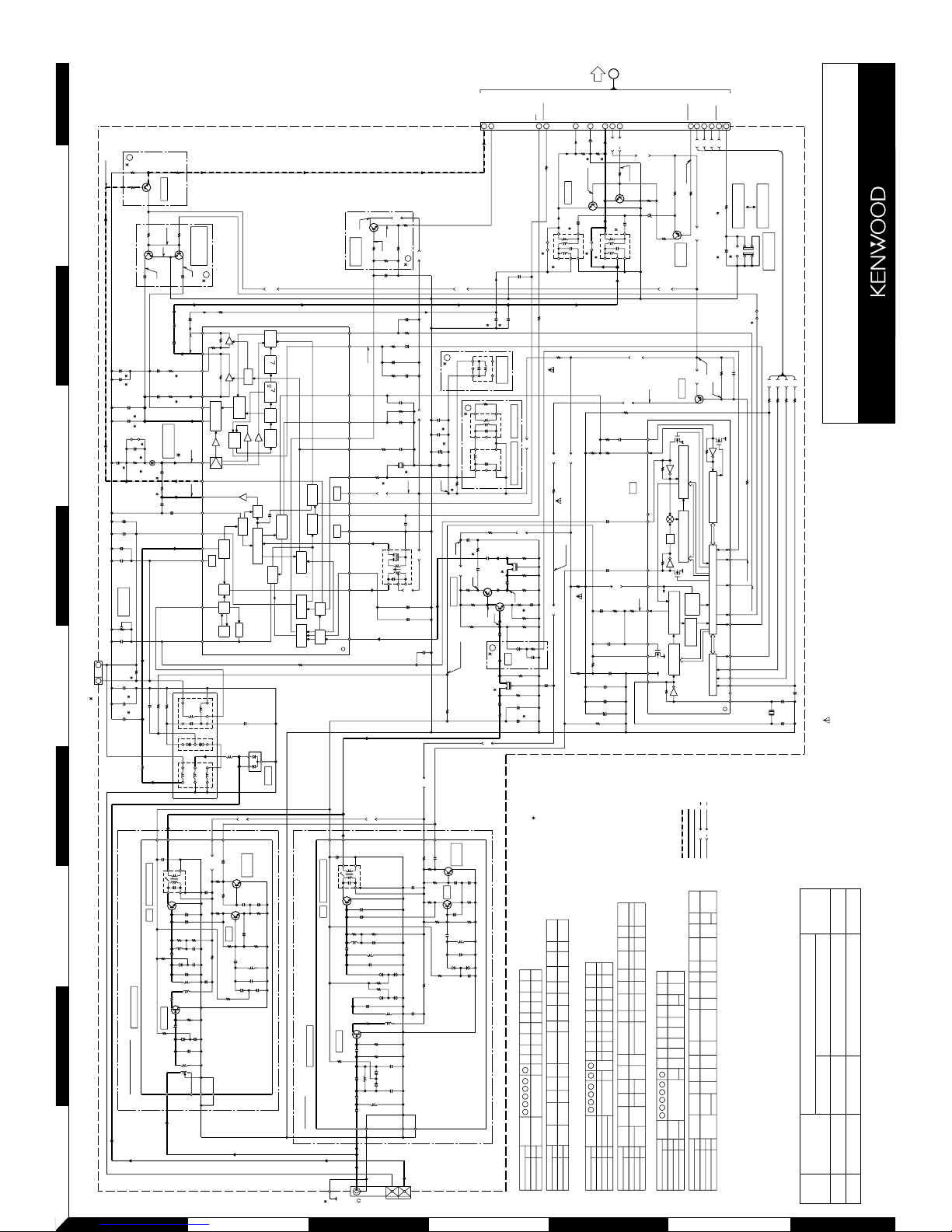
VR-405 (X07-3140-10)/VR-406 (X07-3130-11)/VR-414 (X07-3140-11)
KRF-V4530D (X07-3142-71)/KRF-V6030D (X07-3132-72)/KRF-V6030DE (X07-3132-72)
KRF-V5030D-S (X07-3142-71)/KRF-V6030D-S (X07-313X-XX)
IC201 :
IC202 : LC72131
Q201,203,204,206-209
: 2SD1819A(Q,R) or
2SC4081(R,S)
Q202,212,214
: 2SB1218A(Q,R) or
2SA1576A(R,S)
Q210,211 : 2SD1757K
D201 : DA204U or
1SS302 or
MA143A
D203 : MTZJ8.2(B) or
HZS8.2N(B2)
D204 : MTZJ5.1(B) or
HZS5.1N(B2)
D211,213
: MA 111
D209 : MTZJ3.3(B) or
HZS3.3N(B2)
NATOR
DISCRIMINATOR
DISCRIMI-
KRF-V5030D (X07-314X-XX)/KRF-V5030D-S (X07-3142-71)/KRF-V5030DE (X07-3142-71)
BUFFER
Q207
C
FM
A1 (W02-2622-05)
A1 (W02-2584-05)
(E,T) TYPE
(K,P,M,I,X,Y) TYPE
IC202
IC201
TUNER UNIT (X07-31XX-XX) (B/3)
A
KRF-V6030D/V6030D-S/V6030DE (1/4)
KRF-V5030D/V5030D-S/V5030DE (1/4)
VR-405/406/414 (1/4)
KRF-V4530D (1/4)
3.6V
8.2V
0V
(2.7V)
2.3V
1.3V
(2.3V)
0V
7.1V
(9.2V)
8.8V
(3.9V)
7.0V
1.7V
(1.3V)
0V
4.3V
4.3V
4.3V
3.3V
2.8V
3.6V
3.6V
2.5V
(FM98MHz)
1.0V
(2.6V)
0V
0V
2.6V
4.7V
(0V)
[0.6V]
0V
0V
0V
1.8V
(0V)
11.8V
[75uS]
50uS
0V
1.0V
(5.1V)
8.2V
3.6V
6.3V
1.2V
6.6V
1.2V
3.5V
4.1V
8.2V
OFF: -1.8V
OFF: 4.8V
4.3V
11.7V
2.7V
(0V)
0V
6.8V
0V
(0V)
4.4V
ON: 0.7V
ON: 0.2V
3.8V
0V
(1.3V)
2.8V
7.3V
7.3V
3.6V
3.6V
0V
0.2V
8.2V
(12.0V)
0V
MONO: 0V
11.1V
3.5V (3.0V)
-11.8V
ST: 7.1V
0.5V
10.6V
AM: 0V
FM: 7.3V
(@FM98MHz)
3.8V
5.2V
CAUTION: For continued safety, replace safety critical components only with manufacturer's recommend-
ed parts (refer to parts list). indicates safety critical components. For continued protection against risk
of fire, replace only with same type and rating fuse(s). To reduce the risk of electric shock, leakage-current
or resistance measurements shall be carried out (exposed parts are acceptably insulated from the supply
circuit) before the appliance is returned to the customer.
MODE CARRIER
MODULATION
ANT INPUT
FREQUENCY DEVIATION
FM 98MHz 1kHz STEREO 67.5kHz 7.5kHz(Pilot) 60dB
AM 1000(999)kHz 400Hz MONO 30% MOD 60dB
The DC voltage is an actual reading measured with a high impedance type volt-
meter as the AM/FM signal generator is specified to the conditions as shown in the
list below. The measurement value may vary depending on the measuring instru-
ments used or on the product. The value shown in ( ) is actual reading measured in
the AM mode.
 Loading...