

Kenwood KRF-V8030D, VR-409 User Manual

AUDIO VIDEO SURROUND RECEIVER
KRF-V8030D
VR-409
INSTR UCTION MANUAL
KENWOOD CORPORATION
This instruction manual is used to describe multiple models listed above.
Model availability and features (functions) may differ depending on the country and
sales area.
About the supplied remote control (RC-R0809)...
Compared to standard remote controls, the remote control supplied with this receiver has several operation
modes. These modes enable the remote control to control other audio/video components. In order to
effectively use the remote control it is important to read the operating instructions and obtain a proper
understanding of the remote control and how to switch its operation modes (etc.).
Using the remote control without completely understanding its design and how to switch the operation modes
may result in incorrect operations.
PreparationRemote Control Other
Operations
B60-4593-00 (EN)
Before applying the power
Caution : Read this page carefully to ensure safe
operation.
Units are designed for operation as follows.
2
U.S.A. and Canada........................................... AC 120 V only
Australia ........................................................... AC 240 V only
China and Russia ............................................ AC 220 V only
*Other countries ........... AC 110-120 / 220-240 V switchable
Preparations
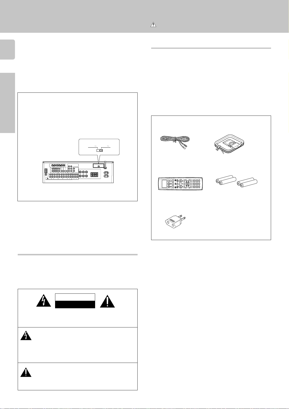
* AC voltage selection
The AC voltage selector switch on the rear panel is set to the voltage that
prevails in the area to which the unit is shipped. Before connecting the
power cord to your AC outlet, make sure that the setting position of this
switch matches your line voltage. If not, it must be set to your voltage
in accordance with the following direction.
AC voltage selector switch
Move switch lever to
match your line voltage
with a small screwdriver or other pointed
tool.
AC 110 120V
AC 110 – 120V ~ AC 220 – 240V ~
AC 220 240V
Unpacking
Unpack the unit carefully and make sure that all accessories are put
aside so they will not be lost.
Examine the unit for any possibility of shipping damage. If your unit is
damaged or fails to operate, notify your dealer immediately. If your unit
was shipped to you directly, notify the shipping company without delay.
Only the consignee (the person or company receiving the unit) can file
a claim against the carrier for shipping damage.
We recommend that you retain the original carton and packing materials for use should you transport or ship the unit in the future.
Keep this manual handy for future reference.
Accessories
FM indoor antenna (1)
Remote control unit (1)
AM loop antenna (1)
Batteries (R6/AA) (4)
Note:
Our warranty does not cover damage caused by excessive line voltage
due to improper setting of the AC voltage selector switch.
Safety precautions
WARNING :
TO PREVENT FIRE OR ELECTRIC SHOCK, DO NOT
EXPOSE THIS APPLIANCE TO RAIN OR MOISTURE.
CAUTION
RISK OF ELECTRIC SHOCK
DO NOT OPEN
CAUTION: TO REDUCE THE RISK OF ELECTRIC SHOCK, DO NOT
REMOVE COVER (OR BACK). NO USER-SERVICEABLE PARTS INSIDE, REFER SERVICING TO QUALIFIED SERVICE PERSONNEL.
*AC plug adaptor (1)
*Use to adapt the plug on the power
cord to the shape of the wall outlet.
(Accessory only for regions where use
is necessary.)
THE LIGHTNING FLASH WITH ARROWHEAD SYMBOL,
WITHIN AN EQUILATERAL TRIANGLE, IS INTENDED TO ALERT
THE USER TO THE PRESENCE OF UNINSULATED “DANGEROUS VOLTAGE” WITHIN THE PRODUCT’S ENCLOSURE
THAT MAY BE OF SUFFICIENT MAGNITUDE TO CONSTITUTE A RISK OF ELECTRIC SHOCK TO PERSONS.
THE EXCLAMATION POINT WITHIN AN EQUILATERAL TRIANGLE IS INTENDED TO ALERT THE USER TO THE PRESENCE OF IMPORTANT OPERATING AND MAINTENANCE
(SERVICING) INSTRUCTIONS IN THE LITERATURE ACCOMPANYING THE APPLIANCE.
Before applying the power
Contents
Caution : Read the pages marked carefully to ensure
safe operation.
Before applying the power ................... 2
Safety precautions .............................................. 2
Unpacking .......................................................... 2
How to use this manual ...................................... 4
Special features .................................................. 4
Names and functions of parts ................ 5
Setting up the system ......................... 7
Connecting audio components ........................... 7
Preparations
Connecting video components ........................... 8
Connecting a DVD player.................................... 8
Digital connections ............................................. 9
Connecting to the AUX IN jacks........................ 10
Connecting the antennas .................................. 10
Connecting the system control ......................... 11
Connecting the speakers ..................................12
PRE OUT connections ......................................12
Channel space switching ..................................13
Preparing the remote control ............................ 13
Preparing for surround sound ............... 14
Speaker settings ...............................................14
3
PreparationsOther
As an ENERGY STAR
tion has determined that this products meets the
ENERGY STAR
This product can save energy. Saving energy reduces air pollution and
lowers utility bills.
®
Partner, Kenwood Corpora-
®
guidelines for energy efficiency.
Maintenance of the unit
When the front panel or case becomes dirty, wipe with a soft, dry
cloth. Do not use thinner, benzine, alcohol, etc. for these agents may
cause discoloration.
In regard to contact cleaner
Do not use contact cleaners because it could cause a malfunction.
Be specially careful not to use contact cleaners containing oil, for
they may deform the plastic component.
Operations
Other
Remote
Control
Normal playback .............................. 16
Preparing for playback ...................................... 16
Listening to a source component ..................... 16
Adjusting the sound ..........................................17
Recording ...................................... 18
Recording audio (analog sources) .................... 18
Recording video ................................................ 18
Recording audio (digital sources) ...................... 18
Listening to radio broadcasts ............... 19
Tuning radio stations ........................................ 19
Presetting radio stations manually .................... 20
Receiving preset stations .................................. 20
Receiving preset stations in order (P.CALL) ...... 20
Ambience effects.............................. 21
Surround modes ...............................................21
Surround play ................................................... 23
DVD 6-channel playback .................................. 24
Convenient functions ........................................ 24
In case of difficulty ........................... 26
Specifications ................................. 27
Quick start guide .............................. 29
Getting the most
from your remote control .................... 31
Remote operation of other components... 39
In case of difficulty ........................... 42
Operations
Remote Control
Before applying the power
How to use this manual
4
This manual is divided in to four sections, Preparations, Operations,
Other, and Remote Control.
Preparations
Shows you how to connect your audio and video components to the
receiver and prepare the surround processor.
We've tried to make setting up your system as easy as possible. However,
since this receiver works with all of your audio and video components,
Preparations
connecting the system can be fairly complex.
Operations
Shows you how to operate the various functions available from the
receiver.
Other
Shows you additional information such as “In case of difficulty” (troubleshooting) and “Specifications”.
Remote Control (Separate booklet)
Includes the “Quick Start Guide,” which shows you how to operate other
components using the remote control, as well as a detailed explanation
of all remote control operations. Once you have registered your components with the proper setup codes, you’ll be able to operate both this
receiver and your other AV components (TV, VCR, DVD player, LD player,
CD player, etc.) using the remote control supplied with this receiver.
Special features
True home theater sound
This receiver incorporates a wide variety of surround modes to bring you
maximum enjoyment from your video software. Select a surround mode
according to your equipment or the software you are going to play and
enjoy! ¡
Dolby Pro Logic & Dolby 3 Stereo
This surround system reproduces theater-like surround sound from
video software marked
The PRO LOGIC mode uses the built-in adaptive matrix circuit to steer
the Left, Center, Right and Surround channel audio signals.
The 3 STEREO mode will redirect the Surround signal to the front left
and right speakers when only the front and center speakers are used.
Dolby Digital (AC-3)
The DOLBY DIGITAL (AC-3) mode lets you enjoy full digital surround
from software processed in the Dolby Digital (AC-3) format. Dolby
Digital (AC-3) provides up to 5.1 channels of independent digital audio
for better sound quality and more powerful presence than conventional
Dolby Surround.
DTS
DTS (Digital Theater System) is a 5.1 channel digital audio format that
provides five full-spectrum channels and one low-frequency (subwoofer)
channel for unprecedented clarity, optimum channel separation and a
(wide) dynamic range.
In the DTS mode, the 5.1 channel digital input from a DTS CD, LD or
DVD disc (carrying the “DTS” marking) can be played in Digital Surround.
Important:
When a DTS disc is played on a CD, LD or DVD player, noise may be
output from the analog output. It is recommended that you connect the
digital output of the player to the digital input of this unit.
.
Memory back up function
Please note that the following items will be deleted from the unit's
memory if the power cord is disconnected from the AC outlet for
approximately 3 days.
• Power mode.
• Input selector settings.
• Device preset.
• Picture output.
• Speaker ON/OFF
• Volume level.
• BASS, TREBLE, INPUT level.
• Subwoofer ON/OFF.
• Dimmer level.
• Monitor ON/OFF.
• MD/TAPE settings.
• 6CH/2CH input setting.
• Listen mode setting.
• Speaker settings.
• Input mode setting.
• Midnight mode setting.
• Broadcast band.
• Frequency setting.
• Preset stations.
• Tuning mode.
Multi channel music (SRS Circle Surround )
SRS Circle surround enables you to listen to multi channel sound from
the stereo source. We assume you have already enjoyed listening to
Dolby digital sound/DTS multi channel sound with your multi speakers.
Now, this time try listening to the stereo source (ex. Audio CD) using
your multi speakers. You may discover a new type of “stereo” sound
through SRS Circle Surround.
New DSP surround modes
The DSP (Digital Signal Processor) used for this receiver incorporates
a variety of high quality adjustable sound fields, like "ARENA" and
"THEATER". It is compatible with almost any kind of program source.
DVD 6-channel input
If you own a DVD player equipped with 6-channel output, this receiver
allows you to obtain the full surround sound impact of DVD source
material featuring multi-channel encoding. Since the source signals are
digital and each channel is input independently, the resulting ambience
is far superior to what can be achieved with conventional surround
sound systems.
Universal IR (InfraRed) remote control
In addition to the basic receiver, the remote control supplied with this
receiver can also operate almost all of your remote controllable audio and
video components. Just follow the simple setup procedure to register the
components you have connected.
MACRO play
The MACRO function lets you perform a series of operations automatically, like turning ON the power of the receiver and connected components, switching the input selectors, and starting playback. (Be sure to
register your components before starting the macro set up procedure.
Names and functions of parts
MUTE indicator
STANDBY
POWER
ON/STANDBY
For U.S.A.
and Canada
Speaker indicator
SP
AB
CLIP
RDS EON PTY
TP
TA NEWS
Speaker selection indicators
Input channel indicators
Output channel indicators
STANDBY
ON/STANDBY
POWER
ON OFF
PHONES
TI.VOL
MUTE
A SPEAKERS B
Frequency display,
Input display,
Preset channel display,
Surround mode display
C
RL
LFE SW
S RSLS
MULTI CONTROL
DTS
SOUND
AUTO SOUND indicator
Display
DOLBY
PROLOGIC 3 STEREO CS 5.1
DIGITAL
INPUT MODESET UP
DIMMER MONITOR
LISTEN MODE
SOURCE DIRECT
AUTOBAND MEMORY
Band indicators
FM
AM
MHz
kHz
INPUT SELECTOR
PRO LOGIC
indicator
S.DIRECT indicator
AUTO SOUND
PRO LOGIC
3 STEREO
DOWN MIX
DIGITAL
S.DIRECT
MONITOR
DSP
AUTO
MEMO
TUNED
MONITOR indicatorDOWN MIX indicator
DSP indicator
3 STEREO indicator
STEREO indicator
AV AUX
S-VIDEO V L – AUDIO – R
DIGITAL indicator
AUTO indicator
ST.
ST. indicator
MEMO. indicator
.
TUNED indicator
VOLUME CONTROL
UPDOWN
5
Preparation
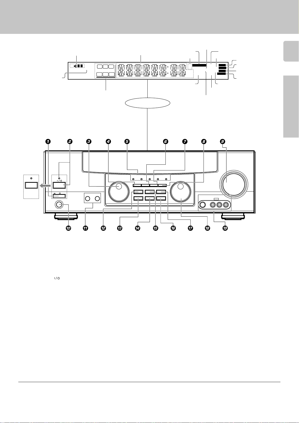
1 POWER key $
(Except for U.S.A. and Canada)
Use to turn the main power ON/OFF.
2 POWER key $
(For U.S.A. and Canada)
Use to turn the power ON/OFF.
STANDBY indicator
2 ON/STANDBY (
) key $
(Except for U.S.A. and Canada)
Use to switch the power ON/STANDBY
when the POWER is turned ON.
STANDBY indicator
3 MULTI CONTROL knob $
Used to make a variety of settings.
4 SET UP key $
Use to select the surround sound settings.
5 Surround indicators
DTS indicator £
Lights when the receiver is in the DTS mode.
DOLBY DIGITAL indicator £
Lights when the receiver is in the Dolby
PROLOGIC indicator £
Lights when the receiver is in the PROLOGIC
mode.
3 STEREO indicator £
Lights when the receiver is in the 3 STEREO
mode.
CS 5.1 indicator £
Lights when the receiver is in the CS 5.1
mode.
6 INPUT MODE key 9
Use to switch between the digital and analog
inputs.
7 DIMMER key *∞
Use to adjust the brightness of the display.
Use to select the REC MODE.
8 MONITOR key *
Use to monitor the source that is connected
to the MONITOR jack.
9 VOLUME CONTROL knob &
0 PHONES jack &
Use for headphone listening.
! SPEAKERS A/B keys &
Use to turn the A/B speakers ON/OFF.
@ SOUND key &
Use to adjust the sound quality and ambience effects.
# BAND key (
Use to select the broadcast band.
$ AUTO key (
Use to select the auto tuning mode.
% LISTEN MODE key £
Use to select the listening mode.
^ MEMORY key )
Use to store radio stations in the preset
memory.
& SOURCE DIRECT key &
Use to pass the source material direct to the
amplifier.
* INPUT SELECTOR knob ^
Use to select the input sources.
( AV AUX (S VIDEO/VIDEO/AUDIO L/R)
jacks 0
Digital mode.
Standby mode
While the standby indicator of the unit is lit, a small amount of current is flowing into the unit’s internal circuitry to back up the memory. This condition is
referred to as the standby mode of the unit. While the unit is in the standby mode, it can be turned ON from the remote control unit.
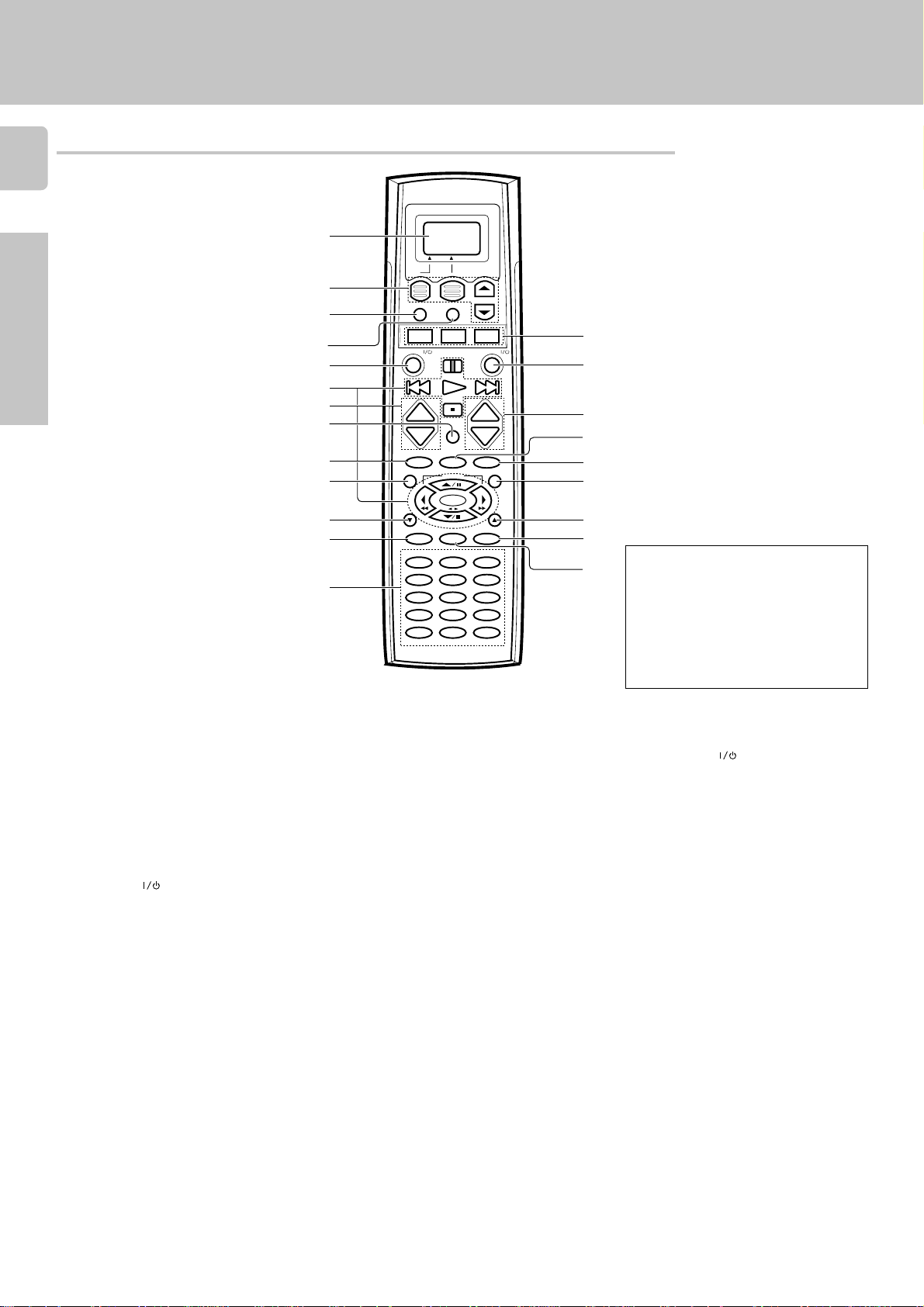
Remote control unit
6
Names and functions of parts
1
Preparations
Page references such as “RC!” indicate pages in the remote control operation
manual (Separate booklet).
1 Display RC1
2 Display operation keys RC1
Used for operation on the display.
3 SHIFT key RC5
Use in combination with the MUSIC and
MOVIE keys to change the remote control
mode without changing the input selector.
4 MACRO key RC6
Use in combination with the MUSIC,
MOVIE, or TV keys to execute a series of
commands automatically (MACRO PLAY).
5 AV.POWER
Use to turn various components on and
off.
6 Multi control keys RC!
Used to make a variety of settings.
Use to operate other components.
7 CH +/– keys RC!
Use to select the channel.
8 MUTE key &
Use to temporarily mute the sound.
9 LISTEN M. key £
Use to select the listening mode.
DIMMER key (with F.SHIFT key)
Use to adjust the brightness of the
display.
Use to select the REC MODE.
0 TITLE/GUIDE key RC@
Use to operate other components.
key
*∞
2
SHIFT MACRO
3
MOVIE TV
4
MUSIC
AV. POWER SYS. POWER
5
6
7
8
9
0
!
@
#
! RETURN/PAGE key RC@
Use to operate other components.
@ REC key RC!
Use to operate the selected component.
# Numeric keys/Source operation keys
Provide functions identical to those of the
original remote control supplied with the
component you are controlling.
To access the functions printed above the
keys, press the numeric key after pressing
the F. SHIFT key. Function availability
varies for each component.
$ MUSIC key ^
Selects the video inputs and sets the
remote control to operate the component
registered at the respective input.
If you connect audio components from
KENWOOD and other makers to the MD/
TAPE or CD jacks, you can set the remote
control to operate these components by
registering the appropriate setup code at
the respective input.
MOVIE key ^
Selects the video inputs and sets the
remote control to operate the component
registered at the respective input.
TV key
Sets the remote control to operate a TV or
+
CH.
CH.
–
DIMMER
LISTEN M. SUB.W.
TITLE/GUIDE MENU
RETURN
/PAGE
INFO. LAST CHANNEL
REMOTE CONTROL UNIT
+
VOL.
VOL.
–
MUTE
BASS BOOST
SOUND
TUNING
BAND
ENTER
AUTO/MONO
F.SHIFTREC LEARN
RANDOMREPEAT INPUT SEL.
213
DISPLAYTV SELECT SELECT
546
THEMEAUDIO FAVORITE
879
EXIT
0+10 +100
1110 12
RC-R0809
/PAGE
OSD
RC!
$
%
^
&
*
(
)
¡
™
There are some cases in which keys (or
knobs) that have the same function on
the receiver and on the remote control
have different names. In the instructions of this manual, if the names of
corresponding keys (or knobs) on the
receiver and remote control are different, the name of the remote control key
is indicated in parentheses.
cable box. This key does not change the
input selector on the receiver.
% SYS.POWER
key ^
Use to turn the receiver on and off.
^ VOLUME +/– keys ^
Use to adjust the receiver volume.
& SOUND key ¢
Use to adjust the sound quality and
ambience effects.
BASS BOOST key (with F.SHIFT key)
Use to select the maximum adjustment
setting for the low frequency range.
* SUB W. key ∞
Use in combination with the VOLUME +/–
keys to adjust the volume of the
subwoofer.
( MENU key RC@
Use to operate other components.
) OSD/PAGE key RC@
Use to operate other components.
¡ LEARN key RC8
Use to memorize the operation of the
other remote control units.
™ F. SHIFT key RC!
Use in combination with the numeric keys
to execute alternate commands.
Turn the light of the display on and off by
pressing and holding this key for more
than 2 seconds.
&
MONITOR
PLAY INPLAY IN
REC OUT
AUDIO
L
R
MD/TAPE1
CD/DVDPHONO
GND
REC OUT
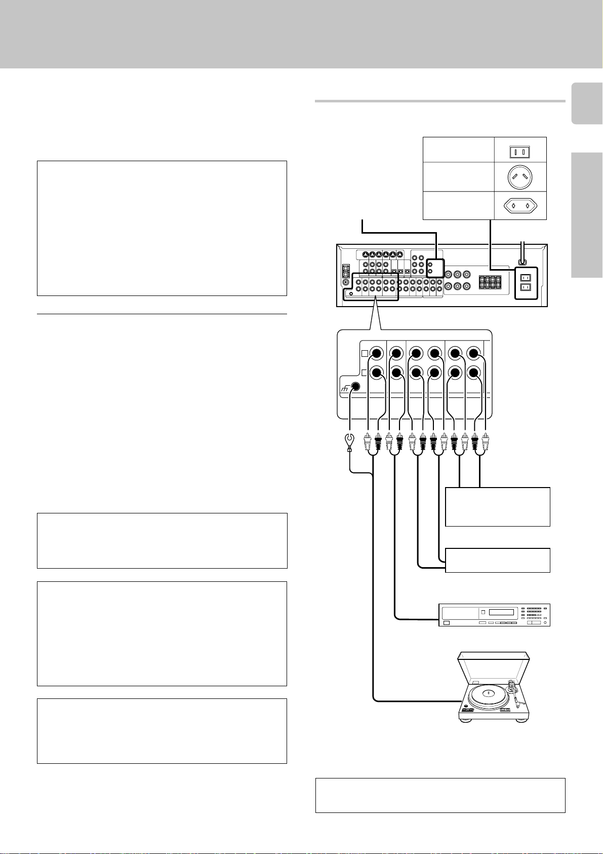
Setting up the system
Make connections as shown below.
When connecting the related system components, be sure
to also refer to the instruction manuals supplied with the
components you are connecting.
Do not connect the power cord to a wall outlet until all
connections are completed.
DTS disclaimer clause
DTS Digital Surround™ is a discrete 5.1 channel digital audio format
available on CD, LD, and DVD software which consequently cannot be
decoded and played back inside most CD, LD, or DVD players. For this
reason, when DTS-encoded software is played back through the analog
outputs of the CD, LD, or DVD player, excessive noise will be exhibited.
To avoid possible damage to the audio system, proper precautions
should taken by the consumer if the analog outputs are connected
directly to an amplification system. To enjoy DTS Digital Surround™
playback, an external 5.1 channel DTS Digital Surround™ decoder
system must be connected to the digital output (S/P DIF, AES/EBU, or
TosLink) of the CD, LD or DVD player.
This unit is equipped with DTS Digital Surround™ decoder.
Notes
1. Be sure to insert all connection cords securely. If their connections are
imperfect, the sound may not be produced or noise may interfere.
2. Be sure to remove the power cord from the AC outlet before plugging or
unplugging any connection cords. Plugging/unplugging connection cords
without disconnecting the power cord can cause malfunctions and may
damage the unit.
3. Do not connect power cords from components whose power consumption is larger than what is indicated on the AC outlet at the rear of this unit.
Connecting audio components
Shape of AC outlets
U.S.A. and Canada
Australia
SYSTEM CONTROL
jacks !
Other countries
To AC wall outlet
7
Preparations
Analog connections
Audio connections are made using RCA pin cords. These cables transfer
stereo audio signal in an “analog” form. This means the audio signal
corresponds to the actual audio of two channels. These cables usually have
2 plugs each end, one red for the right channel and one white for the left
channel. These cables are usually packaged with the source unit, or are
available at your local electronics retailer.
Microcomputer malfunction
If operation is not possible or an erroneous display appears, even though
all connections have been made properly, reset the microcomputer
referring to “In case of difficulty”. §
CAUTION (Except for U.S.A. and Canada)
Be sure to adhere followings. Or proper ventilation will be blocked
causing damage or fire hazard.
• Install the KRF-V8030D on the top of the system.
• Do not place any objects impairing heat radiation onto the top of unit.
• Leave a space around the unit (from the largest outside dimension
including projection) equal or greater than, shown below.
Top panel : 50 cm Side panel : 10 cm Back panel : 10 cm
CAUTION (For U.S.A. and Canada)
Be sure to adhere followings. Or proper ventilation will be blocked
causing damage or fire hazard.
• Install the VR-409 on the top of the system.
• Do not place any objects impairing heat radiation onto the top of unit.
IN OUT
3 head cassette deck or
graphic equalizer *
OUT
MD recorder or
Cassette deck
IN
OUT
CD player
OUT
Record player
When you connect the unit and the CD or MD player with the
digital connection, you can enjoy the higher sound quality.
9
VIDEO
S VIDEO
DVD
PLAY IN
FRONT
L
CENTER DVD
SURROUND
SUB WOOFER
VIDEO 2
COAXIAL
DVD/6ch INPUT
R
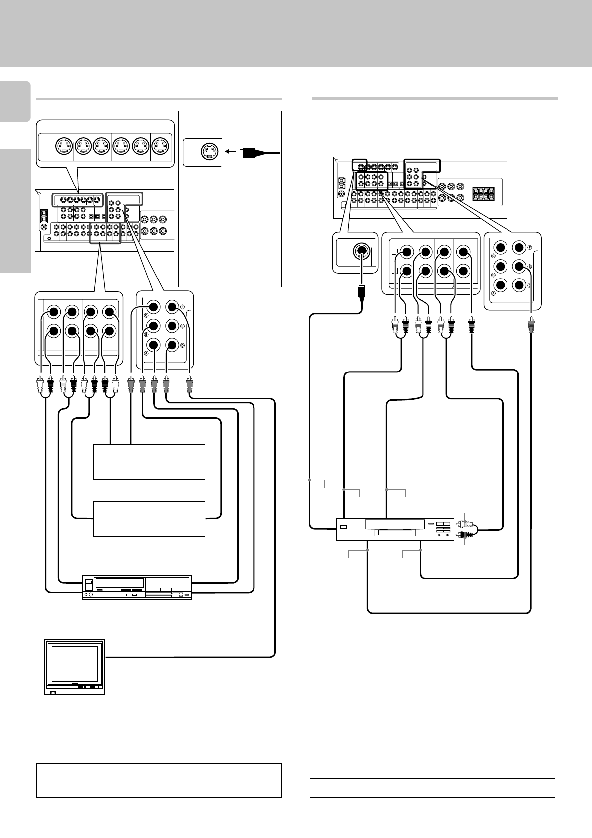
Setting up the system
Connecting video components
8
S Video jacks
PLAY IN REC OUT PLAY IN PLAY IN PLAY IN
S VIDEO
Preparations
VIDEO 1 VIDEO 2 VIDEO 3
DVD VIDEO 1 VIDEO 1 VIDEO 2 VIDEO 3
PLAY IN PLAY INREC OUT
PLAY IN
MONITOR OUT
VIDEO
About the S VIDEO
jacks
S VIDEO
Use the S VIDEO jacks to
make connections to video
components with S VIDEO
IN/OUT jacks.
÷If you use the S VIDEO
jacks to connect your video
playback components, be
sure to use the S VIDEO
jacks when connecting your
monitor and video recording components.
Connecting a DVD player (6-channel input)
If you have connected a DVD player to the receiver with digital connection,
be sure to read the “Input mode settings” section on the following page
carefully.
S VIDEO
cord
OUT
OUT
OUT
Video player
IN
Audio inputs and outputs
Monitor TV
OUT
DVD player or LD player
DVD player or LD player
Video inputs
and outputs
(Yellow RCA pin
cords)
VIDEO IN
Video Inputs
(Yellow RCA pin cord)
OUT
IN
OUT
S VIDEO
OUT
VIDEO OUT
(Yellow RCA
pin cord)
FRONT
OUT L/R
DVD player
SURROUND
OUT L/R
COAXIAL
DIGITAL
OUT
(AUDIO)
CENTER
OUT
SUBWOOFER OUT
A video component with digital audio outputs should be connected to the VIDEO2 or VIDEO3 jacks.
To switch the speakers off , press the MUTE key.
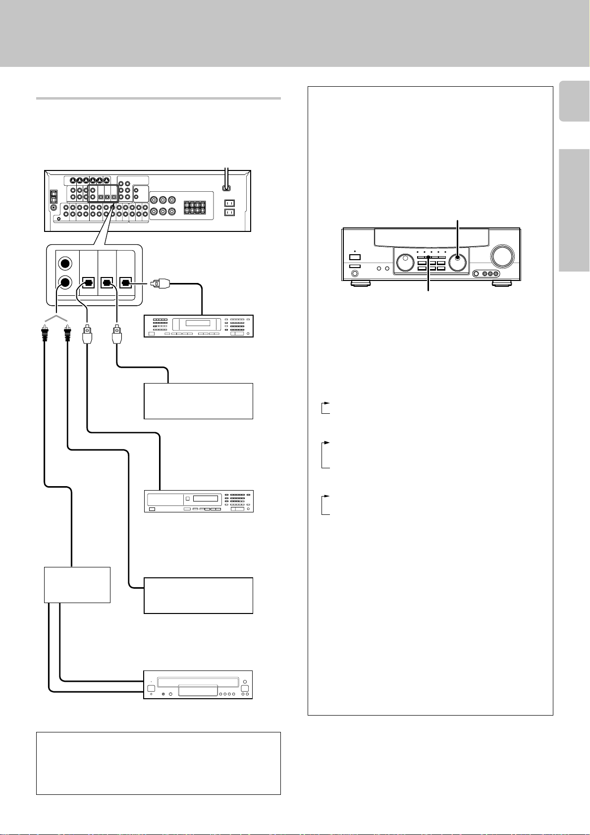
Setting up the system
Digital connections
The digital in jacks can accept DTS, Dolby Digital (AC-3), or PCM signals.
Connect components capable of outputting DTS, Dolby Digital (AC-3), or
standard PCM (CD) format digital signals.
If you have connected any digital components to the receiver, be sure to
read the “Input mode settings” section on this page carefully.
DVD
CD/DVD VIDEO 3 MONITOR
OPTICAL
OPTICAL
OPTICAL
VIDEO 2
COAXIAL
COAXIAL
DIGITAL
OUT
(AUDIO)
DIGITAL IN
DIGITAL OUT
Optical
fiber
cable
OPTICAL DIGITAL IN
(AUDIO)
MD player
OPTICAL DIGITAL OUT
(AUDIO)
Component with an DTS, Dolby
Digital, or PCM OPTICAL
DIGITAL OUT
Connect the video signal and analog audio signals to the VIDEO 3
jacks. (See "Connecting video
components".)
OPTICAL DIGITAL OUT
(AUDIO)
CD player
Input mode settings
CD, DVD, VIDEO2, and VIDEO3 inputs each include jacks for digital
audio input and analog audio input.
You must select beforehand which type of input is to be used for each
connected component.
The initial factory setting is to use the digital audio signal for
playback (CD, DVD, VIDEO2, VIDEO3).
To use the analog audio input for playback instead (if, for example, you
have connected a VCR to the VIDEO2 or VIDEO3 input), you must set
the input mode for the corresponding input to the analog mode.
After completing connections and turning on the receiver, follow the
steps below.
INPUT SELECTOR
INPUT MODE
1 Use the INPUT SELECTOR knob to select CD, DVD, VIDEO2, or
VIDEO3.
2 Press the INPUT MODE key.
Each press switches the setting as follows:
In DTS play mode
1 D-AUTO (digital input, auto sound)
2 D-MANUAL (digital input, manual sound)
In DVD play mode
1 D-AUTO (digital input, auto sound)
2 D-MANUAL (digital input, manual sound)
3 6CH INPT (DVD 6CH input)
4 ANALOG (analog input, manual sound)
In other mode than DTS or DVD play mode
1 D-AUTO (digital input, auto sound)
2 D-MANUAL (digital input, manual sound)
3 ANALOG (analog input, manual sound)
9
Preparations
COAXIAL DIGITAL OUT
RF digital
demodulator
(DEM-9991D)
(sold separately)
(AUDIO)
Component with an DTS, Dolby
Digital, or PCM COAXIAL
DIGITAL OUT
Connect the video signal and analog
audio signals to the VIDEO 2 jacks.
(See "Connecting video components".)
DOLBY DIGITAL RF
OUT (AUDIO)
LD player
PCM OUT
To connect an LD player with a DIGITAL RF OUT, connect the LD
player to the KENWOOD RF digital demodulator (DEM-9991D).
Next, connect the DIGITAL OUT jacks of the demodulator to the
DIGITAL IN jacks of the receiver.
Connect the video signal and analog audio signals to the VIDEO
2 or VIDEO 3 jacks. (See "Connecting video components".)
Digital input:
Select this setting to play digital signals from a DVD, CD, or LD player.
Analog input:
Select this setting to play analog signals from a cassette deck, VCR,
or turntable.
Auto sound:
In the auto sound mode (AUTO SOUND indicator lights), the receiver
selects the listening mode automatically during playback to match the
type of input signal (Dolby Digital, PCM, DTS ) and the speaker setting.
The initial factory setting is auto sound on.
To keep the receiver set to the currently selected listening mode, use
the INPUT MODE key to select “D-MANUAL” (manual sound).
However, even when this setting is selected, there may be cases in
which the listening mode is selected automatically to match a Dolby
Digital source signal depending on the combination of listening mode
and source signal.
FM
75Ω
GND
AM
Setting up the system
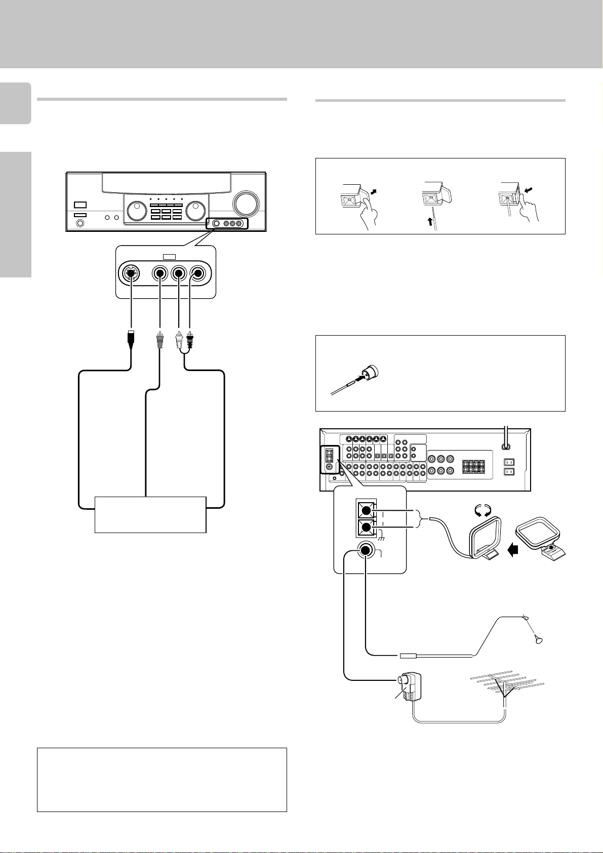
Connecting to the AUX IN jacks
10
The AUX IN jacks are convenient for connection of video components
such as a camcorders and video games.
Preparations
S VIDEO V L – AUDIO – R
S VIDEO cord
AV AUX
Connecting the antennas
AM loop antenna
The supplied loop antenna is for use indoors. Place it as far as possible from
the receiver, TV set, speaker cords and power cord, and adjust the direction
for best reception.
AM antenna terminal connections
1 Push lever. 2 Insert cord.
FM indoor antenna
The supplied indoor antenna is for temporary use only. For stable signal
reception we recommend using an outdoor antenna. Disconnect the indoor
antenna when you connect one outdoors.
FM outdoor antenna
Lead the 75Ω coaxial cable connected to the FM outdoor antenna into the
room and connect it to the FM 75Ω terminal.
FM antenna terminal connections
Insert cord.
3 Return lever.
VIDEO OUT
Camcorder, other VCR,
S VIDEO OUT
• To select the source connected to the AUX IN jacks, select AV
AUX by using the INPUT SELECTOR knob. ^
• When you connect the audio source such as the MD player, you
do not need to connect the video cable.
• When you connect the unit and the component with the S
VIDEO cord, you can get better picture quality.
video game, digital camera,
or portable MD player
AUDIO OUT
Use an antenna
adaptor
(Commercially
available)
Attatch to the stand.
AM loop antenna
FM indoor antenna
FM outdoor antenna
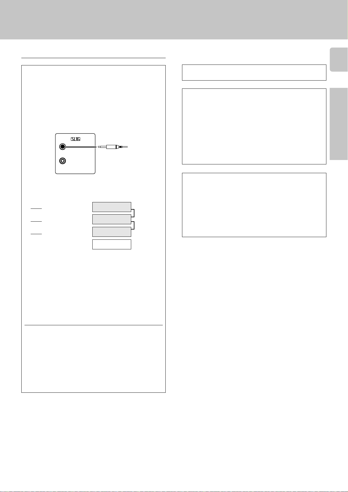
Connecting the system control
Connecting system control cords after connecting a KENWOOD
audio component system lets you take advantage of convenient
system control operations.
Setting up the system
11
Do not connect a system control cord to a cassette deck connected to the MONITOR jacks.
This unit is compatible only with the [SL-16] mode. The system
control operation is not available if the unit is connected in the
[XS-8], [XS] or [XR] connection mode.
If your component has the mode select switch, set the connected
components to the [SL-16] mode.
SYSTEM CONTROL
cord
SYSTEM CONTROL
EXAMPLE: [SL16] mode connections
The underlined portion represents the setting of the system control
mode.
SL16]
[
SL16] [XS 8] [XS] [XR]
[
SL16] [XS 8] [XS]
[
[XS]
• In order to take advantage of the system control operations, the
components must be connected to the correct jacks. To use a CD
player it must be connected to the CD jacks. To use a cassette deck
(or MD recorder) it must be connected to the MD/TAPE jacks. When
using more than one CD player (etc.) only the one connected to the
specified jacks may be connected for system control.
• Some CD players and cassette decks are not compatible with the
[SL16] system control mode. Do not make system connections with
equipment that is not [SL16] compatible.
• Some MD players are not system control compatible. You cannot
make system control connections to this kind of equipment.
Receiver
Cassette deck
or MD recorder
CD player
Record player
SYSTEM
CONTROL
cord
SYSTEM CONTROL OPERATIONS
Remote Control
Lets you operate this unit with the system remote supplied with the
receiver.
Automatic Operation
When you start playback from a source component, the input selector
on this unit switches to that component automatically.
Synchronized Recording
Lets you synchronize recording with the start of playback when recording from CD, MD or analog discs.
Registering setup codes for KENWOOD audio components
• Once you finish making the system connections, be sure to register the
appropriate setup code for each component. RC3
• If you own remote controllable KENWOOD audio components that are
not compatible with system control, registering the setup code enables you to control those components using the remote control
supplied with this unit (without connecting system control cords). To
register setup codes for your remote controllable KENWOOD audio
components, see "Registering setup codes for other components".
RC3
Preparations
Notes
1. [SL16] equipment cannot be combined with [XR], [XS], and [XS8]
equipment for system operations. If your equipment consists of this
kind of combination, please do not connect any system control cords.
Even without system control cords, normal operations can be carried
out without effecting performance.
2. Do not connect system control cords to any components other than
those specified by KENWOOD. It may cause a malfunction and
damage your equipment.
3. Be sure the system control plugs are inserted all the way in to the
system control terminals.
SUB WOOFER PRE OUT
FRONT
SUB
WOOFER
CENTER
SURROUND
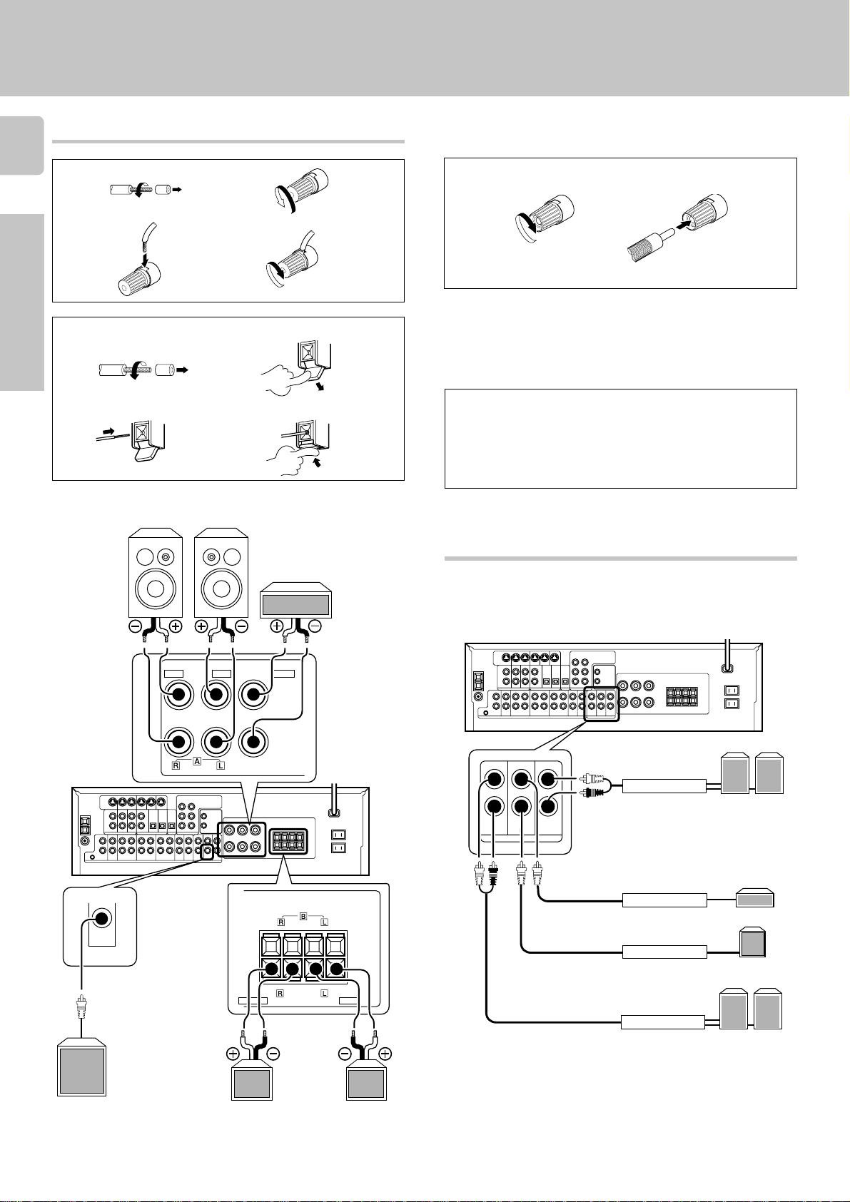
Connecting the speakers
12
1 Strip coating.
3 Insert. 4 Secure.
2 Loosen.
Setting up the system
Connection of banana plugs (For U.S.A. and Canada)
1 Secure.
2 Insert.
Preparations
1 Strip coating.
3 Insert the cord. 4 Return the lever.
Front Speakers A
Right
FRONT SPEAKERS
RED BLUE
(8 – 16Ω)
2 Push the lever.
Left
CENTER SPEAKER
(8 – 16Ω)
Center
Speaker
GREEN
+
• Sound will not be heard if the speaker terminal is not fully secured.
• Never short circuit the + and – speaker cords.
• If the left and right speakers are connected inversely or the speaker
cords are connected with reversed polarity, the sound will be unnatural with ambiguous acoustic imaging. Be sure to connect the speakers correctly.
Speaker impedance
After confirming the speaker impedance indications printed on the rear
panel of the receiver, connect speakers with matching impedance
ratings. Using speakers with a rated impedance other than that indicated on the rear panel of the receiver could result in malfunctions or
damage to the speakers or receiver.
PRE OUT connections
This receiver has additional preout jacks. These can be used for various
purposes, but will need to be connected to an external power amplifier as
shown in the example below.
Powered
subwoofer
SUB
WOOFER
Use the FRONT
SPEAKERS B
terminals if you
want to connect a
second front
speaker system.
–
FRONT SPEAKERS
(8 – 16Ω)
+
SURROUND SPEAKERS
–
(8 – 16Ω)
–
+
GRAYORANGE
Surround
Speakers
LeftRight
(Be sure to connect both
surround speakers)
Power amplifier
Surround
Speakers
Power amplifier
Center Speaker
Subwoofer
Power amplifier
Front
Speakers
Power amplifier
• Connecting a speaker cord directly to a PRE OUT jack will not
produce any sound from the speaker.
• To use the PRE OUT jacks, press only the SPEAKERS A key to the
on position.
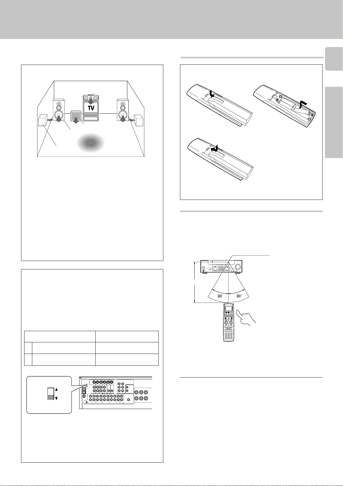
Speaker placement
Center speaker
Setting up the system
Preparing the remote control
Loading the batteries
1 Remove the cover.
2 Insert the batteries.
13
Front
speaker
Surround
speaker
Listening
position
Front speakers : Place to the front left and right of the listening position.
Front speakers are required for all surround modes.
Center speaker : Place front and center. This speaker stabilizes the
sound image and helps recreate sound motion. Be sure to connect a
center speaker when using the Dolby 3 Stereo mode.
Surround speakers : Place to the direct left and right, or slightly
behind, the listening position at even heights, approximately 1 meter
above the ears of the listeners. These speakers recreate sound motion
and atmosphere. Required for surround playback.
Subwoofer : Reproduces powerful deep bass sounds.
• Although the ideal surround system consists of all the speakers listed
above, if you don't have a center speaker or a subwoofer, you can
divide those signals between the available speakers in the speaker
settings steps to obtain the best possible surround reproduction from
the speakers you have available. $
Channel space switching
(Except for the USA, Canada, UK, Europe, and Australia)
The space between radio channels has been set to the one that prevails
in the area to which the system is shipped. However, if the current
channel space setting does not match the setting in the area where the
system is to be used, for instance when you move from area 1 or area
2 shown in the following table or vice versa, proper reception of AM/FM
broadcasts cannot be expected. In this case, change the channel space
setting in accordance with your area by referring to the following table.
Subwoofer
3 Close the cover.
• Insert four R6/AA-size alkaline batteries as indicated by the polarity
markings.
Operation
When the STANDBY indicator is lit, the power turns ON when you press
the SYS.POWER key on the remote control. When the power comes ON,
press the key you want to operate.
Operating range
(Approx.)
6 m
Remote sensor
Preparations
Area
USA, Canada and South
1
2
Move switch lever to match your area with a small screwdriver or
other pointed tool.
American countries
Other countries
DEEMPHASIS
CHANNEL
SPACE
75µs
AM 10kHz
FM 100kHz
50µs
AM 9kHz
FM 50kHz
CHANNEL
Space Frequency
FM: 100 kHz
AM: 10 kHz
FM: 50 kHz
AM: 9 kHz
Infrared ray system
• When pressing more than one remote control key successively, press
the keys securely by leaving an interval of 1 second or more between
keys.
Notes
1. The supplied batteries may have shorter lives than ordinary batteries due
to use during operation checks.
2. When the remote-controllable distance gets shorter than before, replace
all batteries with new ones.
3. Placing the remote sensor in direct sunlight, or in direct light from a high
frequency fluorescent lamp may cause a malfunction.
In such a case, change the location of the system installation to prevent
malfunction.
 Loading...