

KENWOOD KRC-708, KRC-888, KRC-X858, KRC-PS988R Service Manual
KRC-708/ 888/ X858/
PS988R
CASSETTE RECEIVER
SERVICE MANUAL
C
2000-2 PRINTED IN KOREA
B51-7588-00 ( K ) 1790
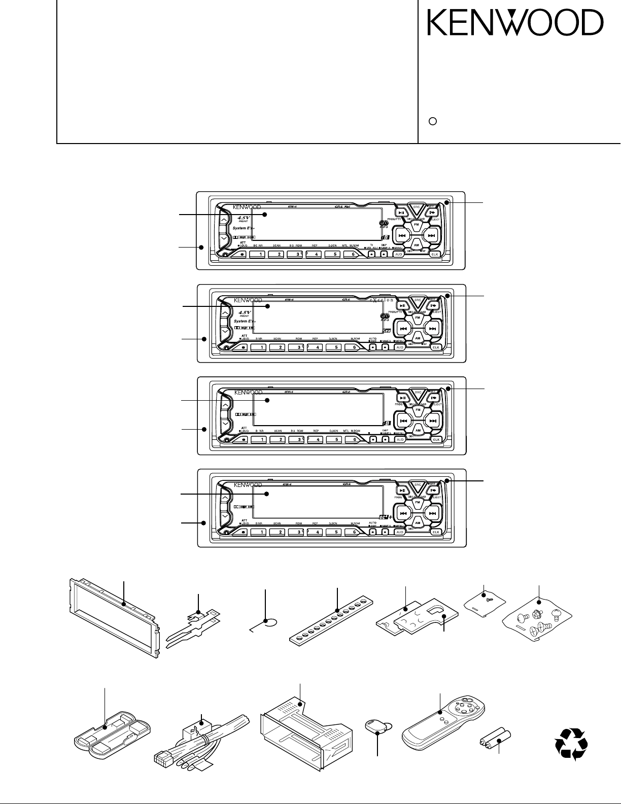
KRC-PS988R
KRC-X858
KRC-888
Front glass
(B10-3101-01)
Escutcheon assy
(B07-2139-03)
Panel assy
(A64-1860-02)
Front glass
(B10-3099-01)
Escutcheon assy
(B07-2146-03)
Escutcheon assy
(B07-2139-03)
Panel assy
(A64-1858-02)
Torsion coil spring
(G01-2924-04)
Lever
(D10-4301-14)
(D10-4302-14)
Remote controller assy
(A70-0886-15)
Remote controller assy
KRC-PS988R/888/708 :(A70-0883-05)
KRC-X858 :(A70-0894-05)
Mounting hardware assy
(J21-9491-03)
DC cord
KRC-X858/888/708 :
(E30-4779-05)
KRC-PS988R :
(E30-4781-05)
Plastic cabinet assy
(A02-1489-03)
The CASSETTE MECHANISM OPERATION DESCRIPTION is the same model D40-1122-05.
Please refer to the service manual for model D40-1122-05(B51-7452-00).
KRC-PS988R
//
.
KRC-X858
B.S/
MTL/
DISP
KRC-708
B.S/
MTL/
DISP
KRC-888
//
.
AUTO
AME
Panel assy
(A64-1861-02)
Panel assy
(A64-1859-02)
Front glass
(B10-3102-01)
KRC-708
Escutcheon assy
(B07-2139-03)
Front glass
(B10-3100-01)
Size AAA battary
(Not supplied)
Stay
(J54-0606-04)
Bracket(L)
(J19-4876-04)
Bracket(R)
(J19-4875-04)
Escutcheon
(B07-2183-02)
Screw set
(N99-1683-05)
Screw set
(N99-1652-05)
40%
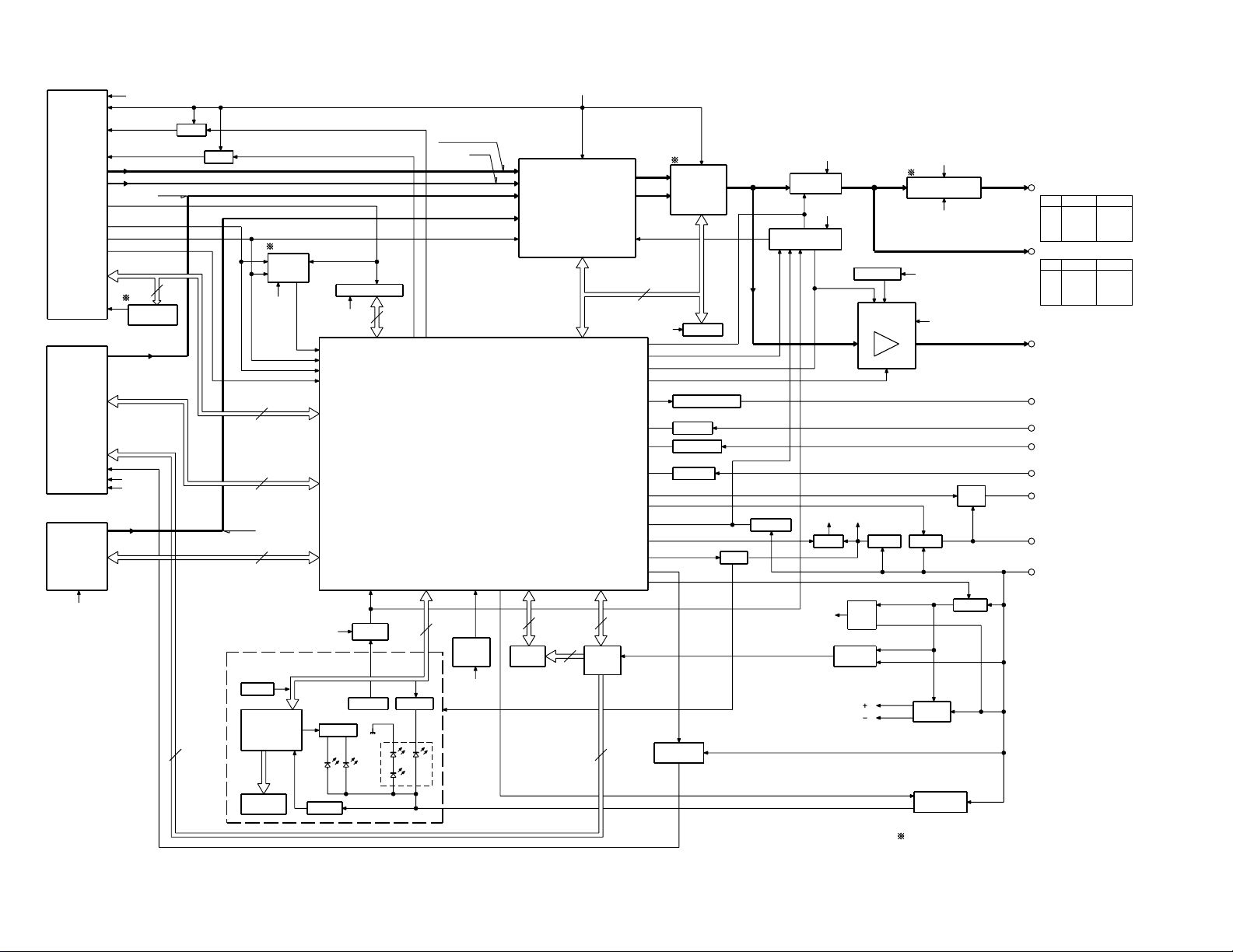
2
FM+B
AM+B
E2PROM
DIMMER
TEL-MUTE
ACC DET.
SRMMECHA
BU DET.
DRIVER
LCD
SUB
DRIVER
A 8V
SUB MOT
SW14V
ILL AVR
SW5V B.U.5V P CON
DRIVER
SYSTEM
E'S
POWER IC
IC4
IC14
Q32
Q23 Q21,22 Q28,29,31
Q25
Q24
SYSTEM u-COM
IC1
Q18-20
Q37,38
MECH
CHANGER
IC10
IC1,2
Q35,36
Q33,40,44
Q1-6
IC5
IC2
F/E
MECHADET.
IC13
E-VOL
Q87,89
Q86,88
SP-OUT
ILL
TEL-MUTE
ACC
P CON
BACK UP
RDS DECODER
IC11
AMP
IC12
NOISE
REMO
IC3
G/A SW
VLCD
4.5V PRE OUT
EXT. AMP CONT
Q39
EXT. AMP CONT
AVR
RST SW
RESET
IC15
POSISTOR
BACK LIGHT
Q8
LCD
MAIN MOT
AVR
Q41,42
DC/DC
IC6
(FOR 4.5V PRE)
4.5V PRE AMP
Q26,27
CON
ANT
ANT CON
IC6
1.8V PRE OUT
WIDE/
NARROW
Q82
N.C.
MPX
MUTE
MUTE LOGIC
P-5V
Q57-62
MOT
SRM
DIMMER
MD-
CD-
CASSETTE
Depeds on the model.
Refer to the parts list.
PLL CLK
CHANGER
F/R
TAPE IN
MODE 3
MODE 1
R REEL
MTL ON/OFF
DOLBY ON/OFF
MODE 2
F REEL
MS MODE
MUTE
DOLBY B/C
CH CLK
CH CON
DATAC
REQ H
CH RST
REQ C
DATAH
TAPE
AM
FM
MUTE
RESET
SRM SW1
SRM DET
SRM SW2
SUB MOT1
RCLK
QUAL
RDATA
FM+B
SDA
SCK
A8V
SW5V
PLL DATA
PLL CE
FM SD
FSD OUT
REQUEST
RDS OUT
SW5V
FM+B
AM+B
S METER
FM SD
NARROW
IF MODE
PLL CE
NOISE
CH MUTE
BACK UP
6
13
8
SW5V
S METER
P MUTE
EXT. AMP CONT
AC GND
DIMMER
PHONE
ACC DET
P CON
BU DET
BEEP
SW5
P-ON
L CLK
L DATAS
L CE
L DATAL
LOCK SW
DIMMER
REMO
BU5V
160mV
1200mV
388mV
2
ILL ON
213mV
MS OUT
MODE 1
MODE 3
TAPE IN
MODE 2
DOLBY ON/OFF
DOLBY B/C
MTL ON/OFF
MS MODE
R REEL
F REEL
F/R
MUTE
MS OUT
400mV: (K) TYPE
: (E) TYPE
3
24
CASS/SRM
SUB MOT2
SUB MOT3
MOTOR
B
B
7
ANT CON
MUTE
+B
-B
CH
(K) TYPE(E) TYPE
AM
3600mV 3600mV
FM
855mV 600mV
TAPE
1372mV 1800mV
1800mV 1800mV
(K) TYPE(E) TYPE
1715mV
2250mV
4500mV
1069mV
CH
FM
AM
TAPE
4500mV
2250mV
2250mV
750mV
SUB+
SUB-
MOT+B
FM
AM
IF SELECT
2
SW5V
AFC
B.U.5V
B.U.5V
BACK UP
SW5V
PRE MUTE
S MUTE
P-5V
SW5V B.U.5V
A 8V
2
22
ILL
REQ H
CH MUTE
CH RST
CH CON
REQ C
DATAH
DATAC
CH CLK
IF MODE
WIDE
PLL DATA
PLL CLK
SW5V
SUB-
SUB+
MOT+B
SW 5V
A 8V
SCK
SDA
SDA
SCK
(X13- )
KRC-X858
KRC-778R/RY
KRC-PS988R
KRC-708
KRC-PS978R
KRC-888
KRC-778RV/RYV
KRC-878R
KRC-708/888/X858/PS988R
BLOCK DIAGRAM
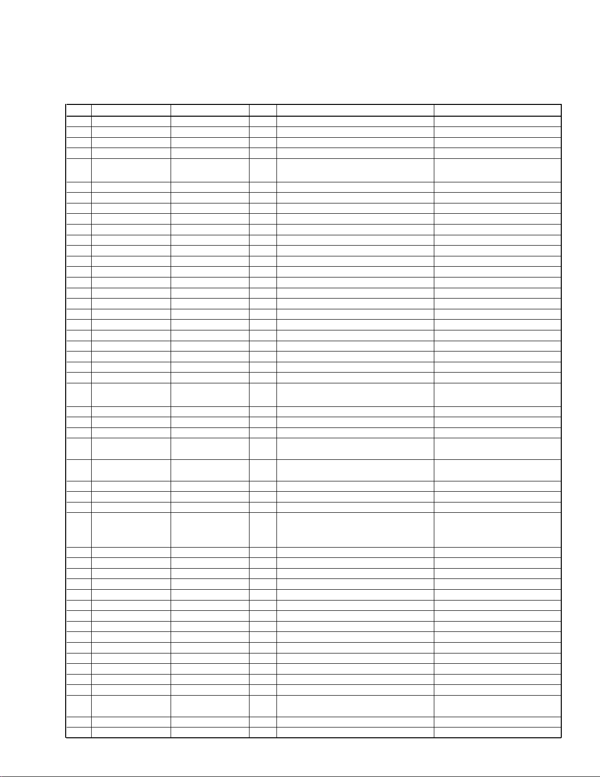
UPD784217GC103(105) (IC1: X14-618X-XX)
System MicroComputer
Pin Pin Name Signal Name I/O Purpose Operation Description
1 P120/RTP0 CHCON O Changer control terminal. ON:Hi, OFF:Lo
2 P121/RTP1 CH_MUTE I Muting input to changer. ON:Hi, OFF:Lo
3 P122/RTP2 REQH O Handshake request to changer.
4 P123/RTP3 DIMMER I Small detection. DIMMER ON:Lo, OFF:Hi
5 P124/RTP4 MOTER O
Cassette mechanism main motor
output.
Active; Hi.
6 P125/RTP5 NC O
7 P126/RTP6 NC O
8 P127/RTP7 NC O
9 Vdd Vdd - Positive power supply.
10 X2 X2 - Main clock connection.
11 X1 X1 - Main clock connection.
12 Vss Vss - GND terminal.
13 XT2 XT2 - Sub-clock connection.
14 XT1 XT1 - Sub-clock connection.
15 RESET RESET I Reset input. Active: Lo.
16 P00/INTP0 CH_RST O Reset output to changer. Active: Hi.
17 P01/INTP1 R_CLK I RDS clock input.
18 P02/INTP2/NMI REQC I Handshake request from changer.
19 P03/INTP3 KEY REQ I
20 P04/INTP4 SUB_MOTOR3 O Sub-motor output. 3
21 P05/INTP5 SUB_MOTOR2 O Sub-motor output. 2
22 P06/INTP6 SUB_MOTOR1 O Sub-motor output. 1
23 AVdd Avdd - A/D analog power supply.
24 AVref0 AVref0 - A/D reference voltage input.
25 P10/ANI0 PHONE I Phone detection.
1 V or less: TEL MUTE
/2.5 V or more: NAVI MUTE.
26 P11/ANI1 SRM_SW1 I SRM position detection. Open: Hi.
27 P12/ANI2 NOISE I FM noise detection.
28 P13/ANI3 SMETER I FM S meter detection.
29 P14/ANI4 F_REEL I
Cassette mechanism reel pulse input
(FWD).
30 P15/ANI5 R_REEL I
Cassette mechanism reel pulse input
(REV).
31 P16/ANI6 N.C. I
32 P17/ANI7 N.C. I
33 AVss AVss - A/D GND terminal.
34 P130/ANO0 EXT_AMP O External amp control.
L 40mS:Bass boost OFF
L 70mS:Bass boost LOW
L 100mS:Bass boost Hi
35 P131/ANO1 IF_MODE I IF status detection for K2I. Hi = WIDE, Lo = NARROW
36 AVref1 AVref1 - D/A reference voltage input.
37 P70/RxD2/SI2 DATAC I Data line from changer.
38 P71/TxD2/SO2 DATAH O Data line to changer.
39 P72/ASCK2/SCK2 CH_CLK I/O Clock line with changer.
40 P20/RxD1/SI1 L_DATAL I Data line from LCD driver.
41 P21/TxD1/SO1 L_DATAS O Data line to LCD driver.
42 P22/ASCK1/SCK1 L_CLK O Clock line to LCD driver.
43 P23/PCL DIMMER O Dimmer control output.
44 P24/BUZ BEEP O Beep output. Active: Hi.
45 P25/SI0 PLL_CE O CE to PLL.
46 P26/SO0 PLL_DATA I/O Data input/output with PLL.
47 P27/SCK0 PLL_CLK O Clock output to PLL.
48 P80/A0 ILL_ON O ILL ON ILL ON : Hi
49 P81/A1 PANEL_5V O
5V power supply control for LCD
driver.
Active: Lo.
50 P82/A2 L_CE O CE terminal to LCD driver
51 P83/A3 LOCK_SW I Panel lock SW detection terminal. Lock SW ON : Lo
KRC-708/888/X858/PS988R
MICROCOMPUTER TERMINAL DESCRIPTION
3
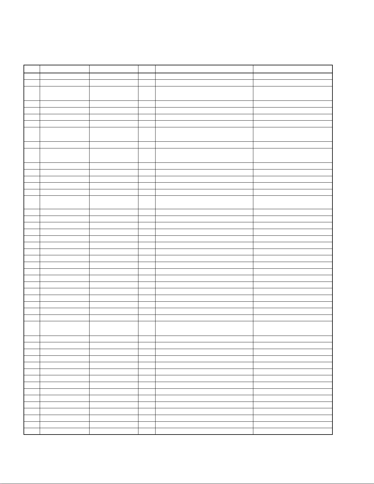
UPD784217GC103(105) (IC1: X14-618X-XX)
System MicroComputer
Pin Pin Name Signal Name I/O Purpose Operation Description
52 P84/A4 WIDE O K2I Forced Wide output. H:Forced Wide
53 P85/A5 NARROW I/O K2I Forced Narrow output. H:Forced Narrow
54 P86/A6 AFC I Noise detection time constant SW
55 P87/A7 SRM_SW2 I SRM eject position detection. EJECT:Hi
56 P40/AD0 QUAL I RDS reception quality.
57 P41/AD1 R_DATA I RDS data input.
58 P42/AD2 SRM_DET I SRM mechanism detection. Detected: Lo /Not detected: Hi.
59 P43/AD3 FM_SD I FM SD input.
Station detected: Hi
/Not detected: Lo.
60 P44/AD4 N.C. O
61 P45/AD5 MUSIC I Blank detection input.
Music detected: Lo
/Music not detected: Hi.
62 P46/AD6 B/C O Dolby B/C switching. B = Lo, C = Hi
63 P47/AD7 Dolby O Dolby output. ON : Hi, OFF : Lo
64 P50/A8 EQ_MUTE O EQ muting output. During play: Lo /FF or REW:
65 P51/A9 MTL O Metal output. NOMAL : Hi, METAL : Lo
66 P52/A10 F/R O Tape EQ input switching. FWD:Lo, REW:Hi
67 P53/A11 MSC O
Blank detection time constant
switching.
During play: Hi /FF or REW:
Lo.
68 P54/A12 MODE3 I Cassette mechanism mode detection.
69 P55/A13 MODE1 I Cassette mechanism mode detection.
70 P56/A14 MODE2 I Cassette mechanism mode detection.
71 P57/A15 PACK_DET I Cassette mechanism pack detection. Pack detected: Lo.
72 Vss GND - GND terminal.
73 P60/A16 TYPE0 I Destination type terminal 0.
74 P61/A17 TYPE1 I Destination type terminal 1.
75 P62/A18 TYPE2 I Destination type terminal 2.
76 P63/A19 ST_TYPE0 I IC2 Ver.3 destination type terminal 0.
77 P64/RD ST_TYPE1 I IC2 Ver.3 destination type terminal 1.
78 P65/WR N.C. O Not used.
79 P66/WAIT N.C. O Not used.
80 P67/ASTB N.C. O Not used.
81 Vdd Vdd - B.U.5V
82 P100/TI5/TO5 SVR O SVR discharge control. POWER OFF:Hi
83 P101/TI6/TO6 PREMUTE O PRE mute. Active: Lo.
84 P102/TI7/TO7 PMUTE O Power IC muting. P IC ON : Hi
85 P103/TI8/TO8 CASS/SRM O
Cassette mechanism / SRM
mechanism voltage SW terminal.
C mech.:Hi, SRM mech.:Lo
86 P30/TO0 ANT_CON O Antenna control. Active: Hi.
87 P31/TO1 AM+B O AM power supply. Active: Hi.
88 P32/TO2 FM+B O FM power supply. Active: Hi.
89 P33/TI1 P_CON O Power control. Active: Hi.
90 P34/TI2 ACC_DET I Acc detection. Acc OFF:Hi.
91 P35/TI00 REMO I Remote control input.
92 P36/TI01 P_ON O Power supply control. POWER ON:Hi
93 P37 BU_DET I Momentary power down detection. Power down: Hi.
94 TEST TEST - Test terminal.
95 P90 IC2_SDA I/O IC2, IC5 and EEPROM data line.
96 P91 IC2_SCK O IC2, IC5 and EEPROM clock line.
97 P92 MUTE O Muting terminal. OPEN:MUTE ON
98 P93 SW5V O 5 V power supply. Lo=SW5 ON
99 P94 N.C. O Not used.
100 P95 N.C. O Not used.
KRC-708/888/X858/PS988R
MICROCOMPUTER TERMINAL DESCRIPTION
During reception: Hi
/During search: Lo.
4

KRC-708/888/X858/PS988R
TEST MODE
2000 MODEL
(1) How to enter the test mode
Reset the set while holding the FM and preset 6 keys
depressed.
All indications light up at the moment the test mode
starts.
(2) How to exit from the test mode
Reset the set while holding the preset 6 key.
(Note) The test mode is not canceled by turning Acc OFF,
turning power OFF or causing momentary power down.
(3) FM S meter voltage adjustment
1. Enter the test mode.
2. While holding the preset 1 key depressed, press and
hold the preset 6 key.
3. "ADJ OK" is displayed when the result is OK or "ADJ
NG" is displayed when it is No Good.
(4) AM SD voltage write
1. Enter the test mode.
2. While holding the preset 1 key depressed, press and
hold the preset 6 key to write the SD voltage data.
(5) Forced Auto/Manual switching of K2I
Press and hold the TI key in the TUNER mode to switch
between AUTO and MANUAL.
The initial status is MANUAL, which is indicated by the
lighting of the TI dots.
(6) Forced Narrow/Wide switching of K2I
Press the preset 6 key in the TUNER mode to switch
between Forced Narrow and Wide.
The initial status is Wide, which is indicated by the lighting of the NEWS dot.
(7) TAPE test mode specification
o The blank skip function is initially turned off.
(8) Audio adjustments
o The volume should be set to -10 dB (displayed as "30").
o The bass/treble and balance/fader controls are set to
full boost/full cut and full front/full rear respectively by
single press of the UP/DOWN key.
o The high-pass filter is set to Through/100 Hz/200 Hz by
each press of the UP key, or to 200 Hz/100
Hz/Through by each press of the DOWN key.
(9) Back-up current measurement
When the set is reset while Acc is off (i.e. when the backup power is on) or when Acc is turned off in the middle of
test mode, the MUTE pin turns ON in 2 seconds instead
of 15 seconds. (The panel/CD/C/MD mechanism is not
activated at this time.)
(10) Procedure for security code registration after
the E2PROM replacement during servicing
(KRC-888 only)
1. Enter the test mode (see "(1) How to enter the test
mode").
2. Press the SRC key to select ALL OFF.
3. Press and hold the AUDIO key for 1 second to enter the
menu mode.
4. Press the FM/AM key to select "SECURITY".
5. Press and hold the Track UP/DOWN key for 2 seconds.
6. Enter the security code by pressing the preset 1, 2, 3
and 4 keys.
Example: To enter "3510"
- Press preset key "1" 4 times.
- Press preset key "2" 6 times.
- Press preset key "3" 2 times.
- Press preset key "4" 1 time.
7. Press and hold the DISP key for 3 seconds so that
"APPROVED" is displayed.
8. Exit from the test mode (see "(2) How to exit from the
test mode").
(11) Simplified security code clear procedure
(KRC-X858, KRC-708)
1. During the code request mode, while holding the DISP
key depressed, press and hold the Volume UP key for
3 seconds (so that "----" disappears).
2. Enter "KCAR" from the remote control unit. (Same operation as with the '98 models)
- Press numeric key "5" 2 times and press the Track UP
key (to enter "K").
- Press numeric key "2" 3 times and press the Track UP
key (to enter "C").
- Press numeric key "2" 1 time and press the Track UP
key (to enter "A").
- Press numeric key "7" 2 times and press the Track UP
key (to enter "R").
3. The security is canceled and the set enters the TUNER
mode.
(12.1) MASK key write procedure in production line
(when the E2PROM is in the initial status)
1. While holding the FM and preset 6 keys depressed,
press RESET to enter the test mode.
2. Press and hold the AUDIO key for 1 second to enter
the menu mode.
3. Press the FM or AM key to select "Mask key".
4. Press the Track UP/DOWN key shortly so that
"TRANSMIT1" is displayed.
5. Point the MASK key to the light sensor and press and
hold the key for more than 0.5 second.
6. When "TRANSMIT2" is displayed, press and hold the
MASK key again for more than 0.5 second. Note that
the first and second counter codes are not compared
at this time.
7. The write operation is complete when "APPROVED" is
displayed. At this time, the demonstration mode is set
and the test mode is canceled.
(Note) Similarly to the '98 models, leaving the set for more
than 30 minutes without writing the code causes an
error and turns power off.
5

KRC-708/888/X858/PS988R
TEST MODE
(12.2) Procedure for canceling the MASK key
request (when the set is reset or the back-up
power is turned off while the MASK key is
enabled)
1. When the power is supplied and the set is switched on,
"TRANSMIT1" is displayed and the MASK key request
mode starts.
2. Point the MASK key toward the light sensor and press
and hold for more than 3 seconds (until the level indicator indicates the full condition).
3. When "TRANSMIT2" is displayed, press and hold the
MASK key again for more than 3 seconds.If "TRANSMIT1" is displayed now, go back to step 2 and restart
from there again.
4. When "APPROVED" is displayed, the MASK key is
enabled and the set is turned on.
(12.3) Procedure for MASK key initialization
(Resetting the MASK key enabled condition to
the factory-set condition)
1. While holding the FM and preset 6 keys, press RESET
to enter the test mode.
2. "TRANSMIT1" is displayed and the MASK key request
mode starts.At this time, the display shows "* *" in
place of "[ ]".
3. Press the MASK key cancel remote control for more
than 3 seconds.
4. When "TRANSMIT2" is displayed, press and hold the
MASK key again for more than 3 seconds.
5. When "APPROVED" is displayed, the MASK key is
canceled, the demonstration mode is set, the test
mode is canceled and the set returns to the factory-set
condition.
(12.4) MASK key all-clear procedure
1. While holding the FM and preset 6 keys, press RESET
to enter the test mode.
2. Press and hold the AUDIO key for more than 1 second
to enter the menu mode.
3. Press the Track UP/DOWN key to select "Mask key".
4. Press and hold the FM or AM key for more than 2 seconds so that "TRANSMIT1" is displayed.
5. Point the MASK key cancel remote control toward the
light sensor and press for more than 3 seconds (until
the level indicator indicates the full condition).
6. When "TRANSMIT2" is displayed, press and hold the
MASK key again for more than 3 seconds.If "TRANSMIT1" is displayed now, go back to step 2 and restart
from there again.
7. When "APPROVED" is displayed, the E2PROM is
cleared entirely and the condition in "(14) MASK key
write procedure in production line (when the E2PROM
is in the initial status)" returns.
(13) Other
o Automatic panel closing when the TAPE/CD/MD is
inserted is disabled.
o Pressing the ATT key ON/OFF opens or closes the
panel. (The ATT operation can be activated from the
remote control unit.)
o The DNPP/SBF key of the remote control unit (RC-510)
functions as the menu mode ON/OFF key.
o The OPEN/CLOSE key of the remote control unit (RC-
510) functions as the audio adjustment mode ON/OFF
key.
o The menu feed operations occur only with the necessary
features.
o Display such as "CODE OFF" is not displayed at the
moment power is turned on.
o Pressing the TI (AUTO) key during the changer opera-
tion turns 2zone on, and pressing the TI (AUTO) key
again cancels it. The P/S dot lights during the 2zone
operation.
o Pressing and holding the MENU key for more than 1
second while ALL OFF initiates the MASK KEY write
mode.
o The dimmer control of the FL models or the contrast
control of the LCD models can be adjusted only to
0/5/10 using the UP/DOWN keys.
6
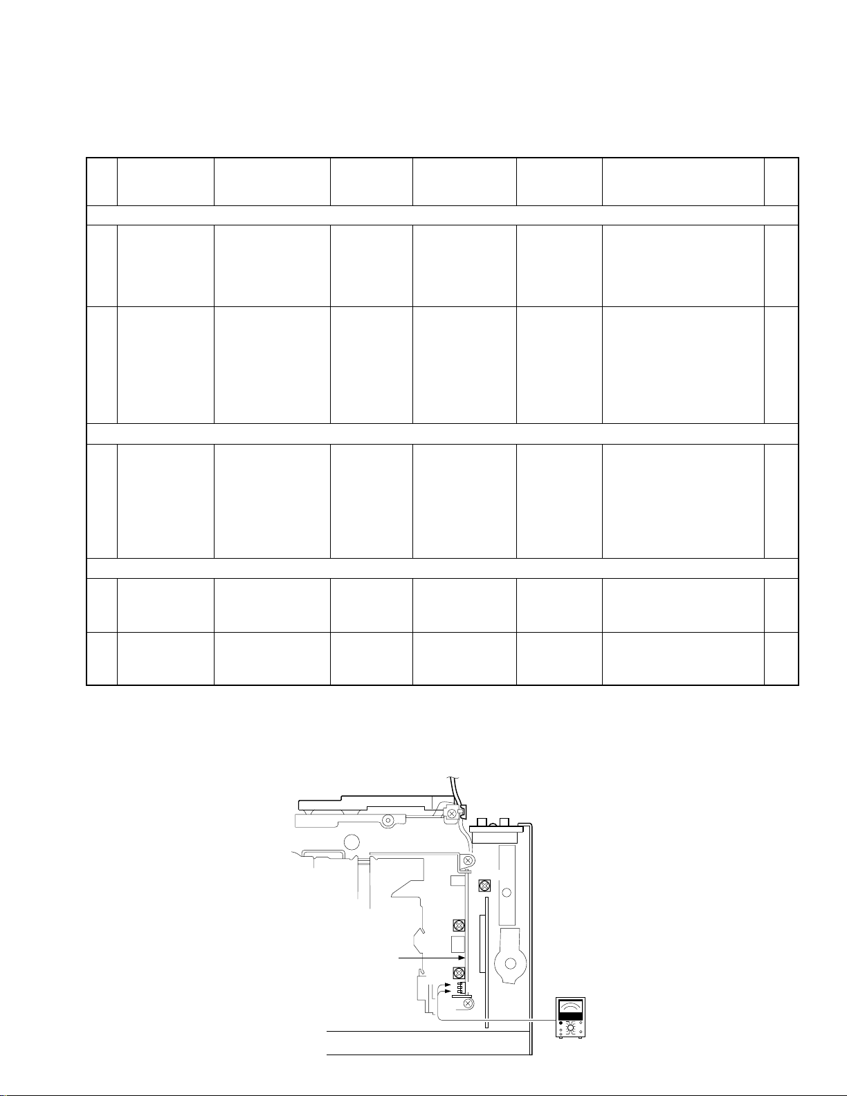
KRC-708/888/X858/PS988R
No ITEM INPUT SETTINGS
OUTPUT
SETTINGS
TUNER
(RECEIVER)
SETTINGS
ALIGNMENT
POINTS
ALIGN FOR FIG.
FM SECTION
1
SEPARATION
(NARROW)
for M
(K2I) model.*
98.1MHz
1kHz,±67.5kHz dev
Pilot:±7.5kHz dev
Selector:L or R
60dBµ (ANT input)
Connect a
AC voltmeter
to SP OUT
TEST MODE:ON
(Forced Narrow)
FM 98.1MHz
VR1
(X14-)
Adjust it so that the
crosstalk from L to R and R
to L become minimum.
2
S METER
VOLTAGE
98.1MHz 0 dev
35dBµ (ANT input)
–
TEST MODE: ON
FM
98.1MHz
Preset "1"key,
and
preset "6" key
While holding preset "1"
key, press and hold preset
"6" key for a few seconds.
"ADJ OK" is displayed if the
adjustment is OK and "ADJ
NG" is displayed if it is not
good.
AM SECTION
(1) SD VOLTAGE
990 kHz
0% mod
35dBµ (ANT input)
–
TEST MODE: ON
AM
990 kHz
Preset "1"key,
and
preset "6" key
While holding preset "1"
key, press and hold preset
"6" key for a few seconds.
"ADJ OK" is displayed if the
adjustment is OK and "ADJ
NG" is displayed if it is not
good.
CASSETTE DECK SECTION
[1] AZIMUTH
TCC-153
10kHz
Connect a
AC voltmeter
to SP OUT
TAPE PLAY
Head Azimuth
Screw
Adjust the azimuth for each
Lch/Rch or FWD/RVS
becomes maximum
[2]
PLAY BACK
LEVEL
TCC-130
Connect a
AC voltmeter
to CN2
TAPE PLAY
VR1 (L)
VR2 (R)
(X87)
387.5mV (-6dBm) (a)
TEST MODE : ON While holding the "FM" key and preset "6" key, reset the unit.
*M (K2I) model: KRC-PS988R
(Forced Narrow) Press "SRC" key. Tuner mode ON.
Press preset "6" key. "NEWS" goes OFF.
Set the controls and switches as follows.
BALANCE :center position BASS :center position LOUD :OFF DOLBY NR :OFF
FADER :center position TREBLE :center position
VR2
(R ch)
L
G
R
VR1
(L ch)
F/E
X87-301X-XX
X14-618X-XX A/2
(a) 387.5mV
AC voltmeter
CN2
VR1 (sep.)
ADJUSTMENT
7
ACEBD
C15
R28
R26
C19
R9
OPEN
OPEN
R6
R8
R5
R2
R1
R4
R3
R10
R24 R23
R29
R27
R15
R12
R11
R14R13
C11
C10
C9
C14
C13
C12
C8
C3
C2
C1
C6
C5
C4
R31
C16
R19
R20
R17
R18
R21
R25
R22
R16
C7
CP1
C17
R30
1
1
ILL+B
KI5
KS3
KS2
KS1
KI4
KS4
KI3
KS5
KI2
KI1
ILL G
RESET
LOCK SW
DIMMER
DGND
VDD
REMO
L DATAL
L DATAS
L CLK
L CE
EB
EB
E
B
E
B
E
B
EB
EB EB
25
5175
76
100
26
50
75
76
100
25
26
50
51
1
2
14
15
100
76
BE
R25
C19
R19
R31
KI1
ILL G
B
C15
BE
C16
E
E
C4
C1
C6
C2
C3
R2
B
C5
B
E
R3
R1
R4
R18
RESET
R26
R28
C7
C14
KI2
R9
KS5
KI3
R5
1
LOCK SW
26
25
R10
75
KS4
KI4
R21
KS1
51
50
C11
C8
C9
C10
R11
R12
DIMMER
R30
C17
100
C12
VDD
1
R13R14
R27
BE
DGND
R15
76
75
KS2
26
25
REMO
R23
R8
R29
R24
R6
50
51
EBEB
15
1
2
14
L DATAS
L DATAL
CP1
R16
R20
L CLK
L CE
R22
ILL+B
KS3
R17
C13
KI5
IC1
CN1
Q3
Q8
Q2
Q1
Q5
Q4
Q7
Q6
D1
IC2
S23
S22
Q2
Q6
Q7
Q5
S23
Q1
IC1
S22
D1
Q8
IC2
Q4
Q3
CN1
S2
S3
S4
S5
S6
S7
S8
S9
S10
S11
S12
S13
S21
S15
S16
S17
S14
S18
S19
S20
RESET
IC3
D6
D5
S1
D3
D2
D4
X13-9720-10 (J74-0984-12)
ED1
S12
S19
IC3
S14
S15
S20
RESET
D4
D2
D3
S6S1
S3
S7S9
S10
ED1
S13 S11S2
D5
S18
S21
S17
S5
S16
S4
S8
X13-9720-10 (J74-0984-12)
D6
4
3
1
2
18 9 1819 64
65119
120
139
EJECT
SRC
FM
AM
CLKAUD
DISCAUTO653421ATT
EJECT
4
3
2
139
1
1
ATT
1
119
120
891819
2
345
65
64
SRC
FM
AM
AUTO 6DISC
AUD
CLK
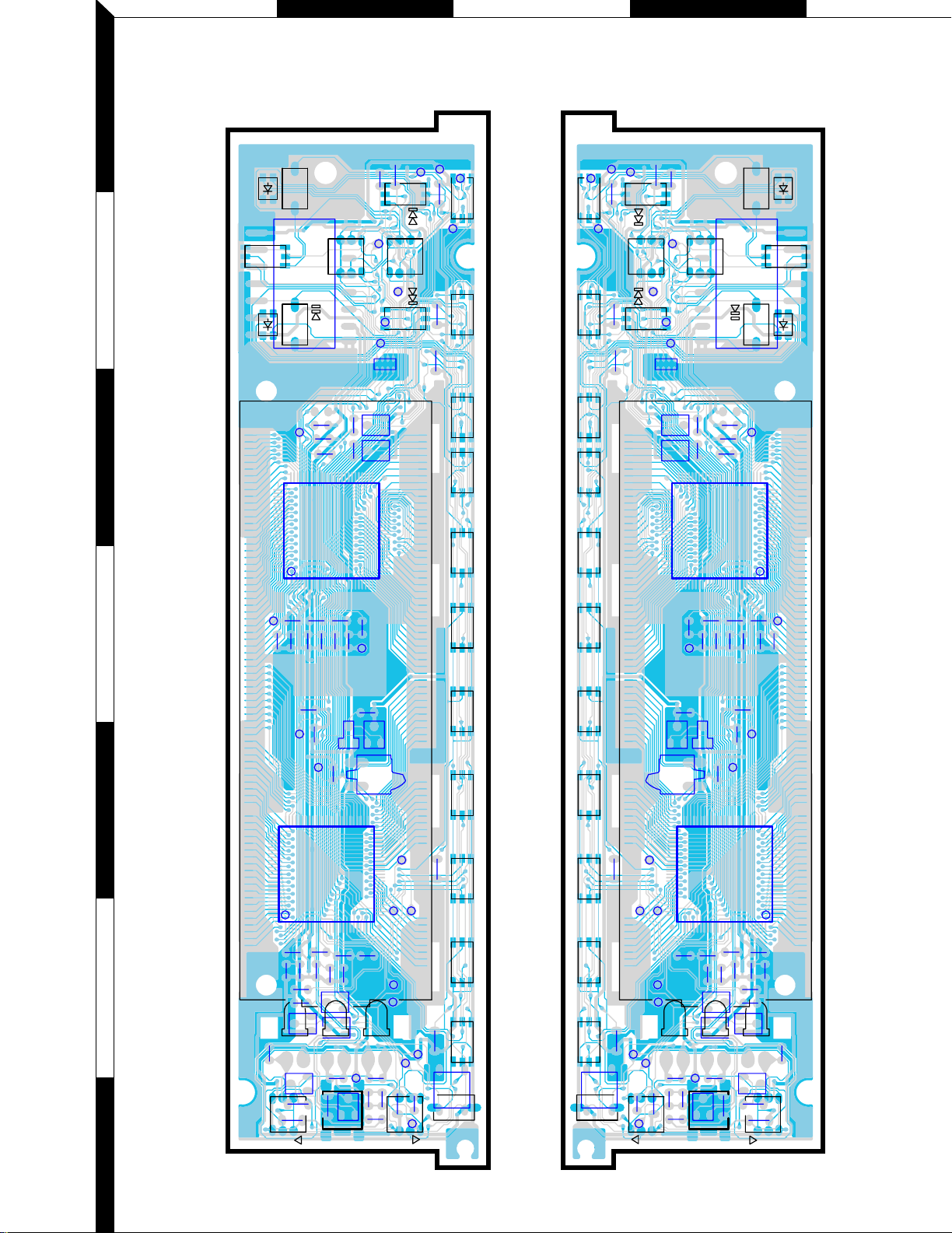
PC BOARD
1
(Component side view) (Foil side view)
2
3
4
5
6
7
Refer to the schematic diagram for the value of resistors and capacitors.
8
 Loading...