

Kenwood KRC-597 Service Manual
CASSETTE RECEIVER
KRC-597/597Y
SERVICE MANUAL
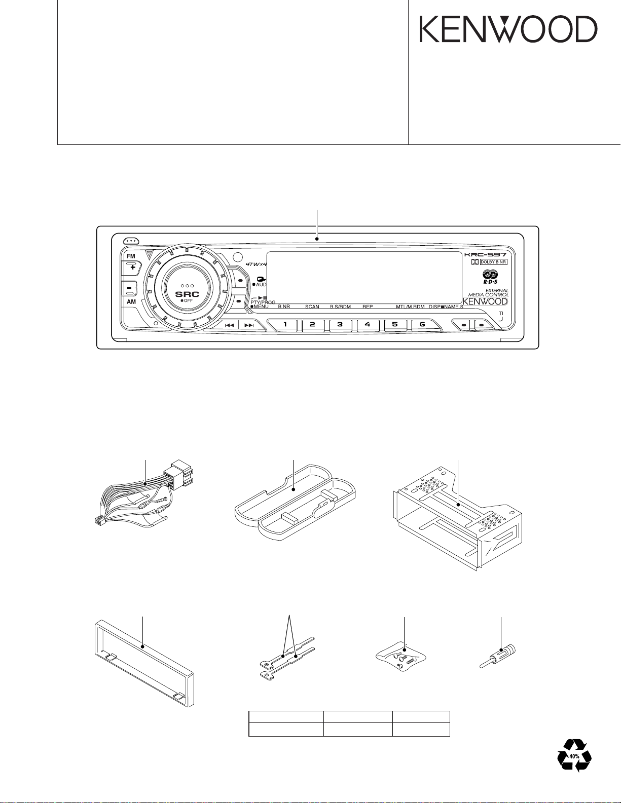
Panel assy
(A64-3201-02)
© 2003-11 PRINTED IN JAPAN
B53-0107-00 (N) 1839
DC cord
(E30-6286-05)
Escutcheon
(B07-3083-02)
Plastic cabinet assy
(A02-1486-13)
Lever
(D10-4589-04)
TDF PANEL INFORMATION
MODEL TDF PANEL No. TDF NAME
KRC-597/597Y Y33-1930-68 TDF-597
x2
Screw set
(N99-1730-15)
Mounting hardware assy
(J22-0011-03)
Antenna adaptor
(T90-0523-05)
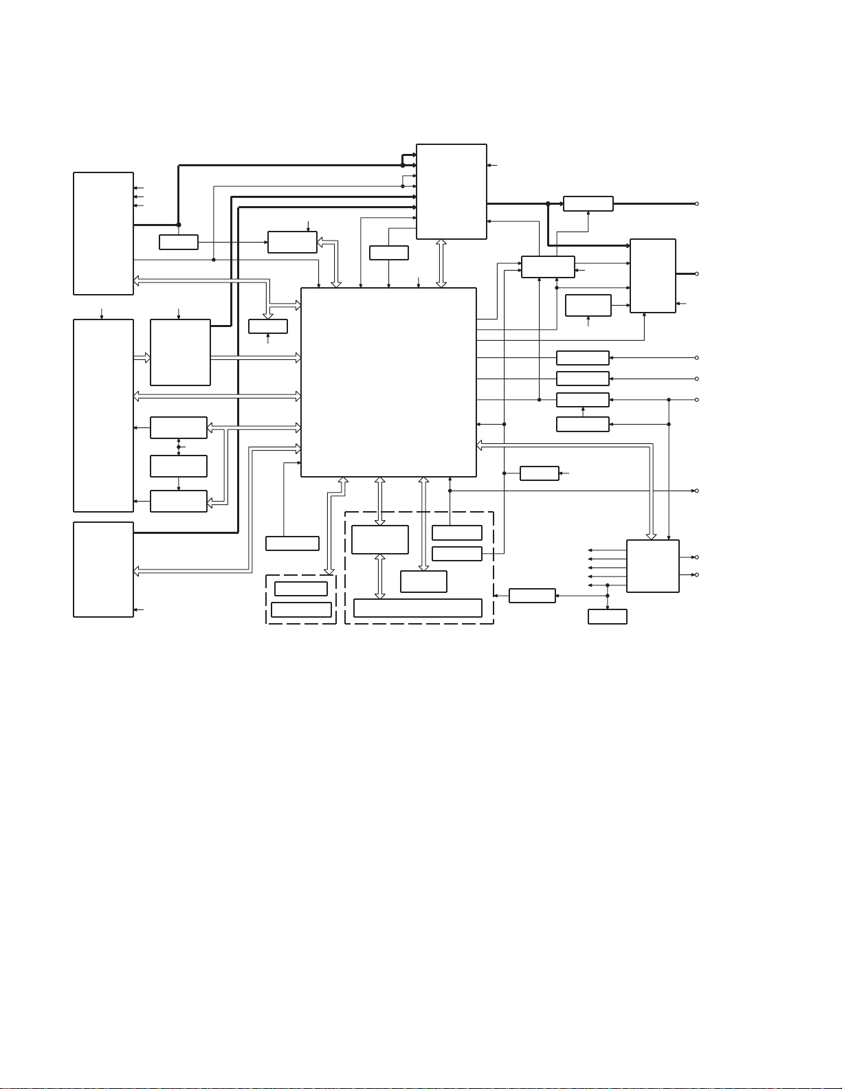
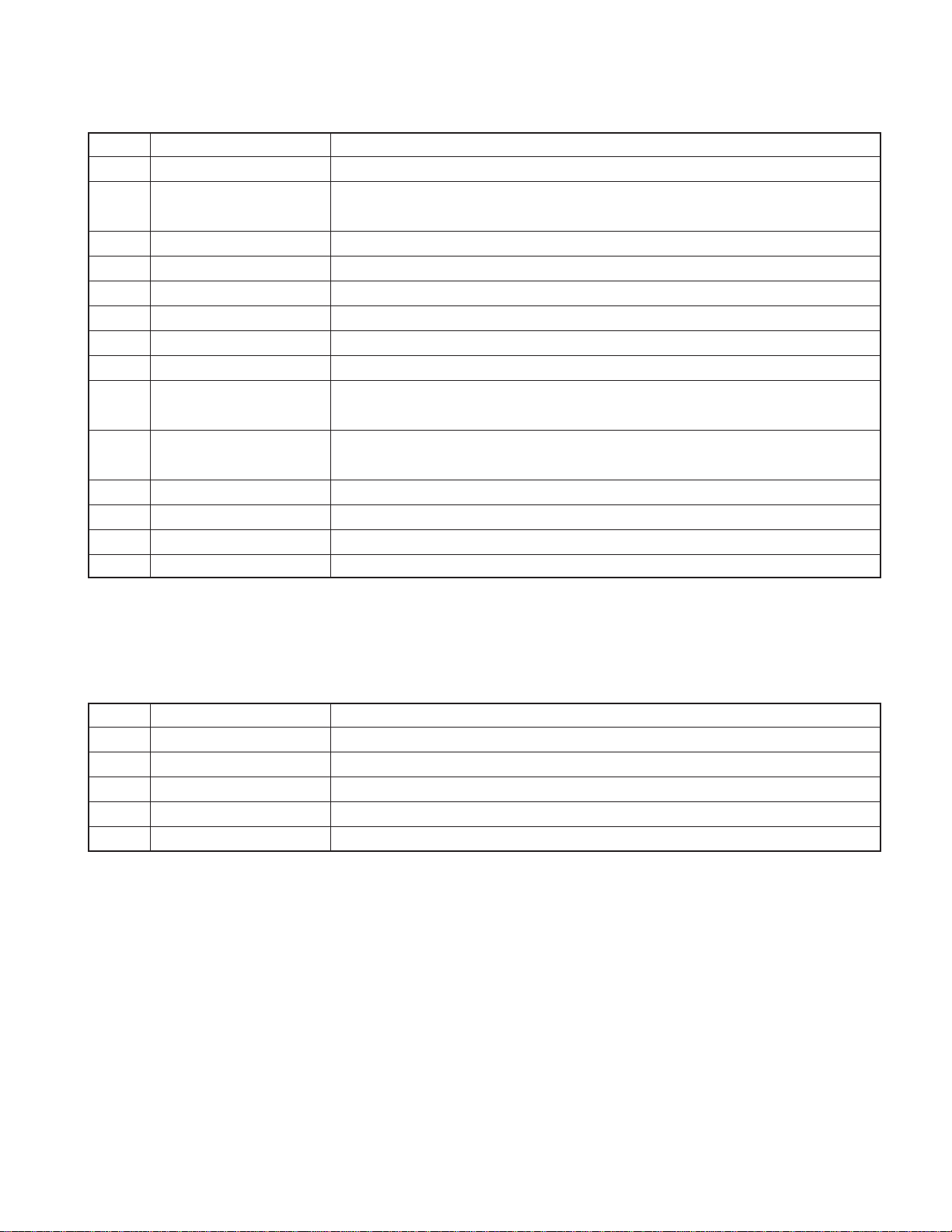
KRC-597/597Y
BLOCK DIAGRAM
(X14- )
TUNER
AUDIO OUT
S-METER
PLL-DATA
PLL-CLK
IFC OUT
SW5V A8V
CASSETTE
FOR(L)
FOR(R)
REV(L)
REV(R)
R REEL
F REEL
MODE1
MODE2
MODE3
MOT +B
SUB+
SUB-
CH
LX REQ S
LX CLK
LX DATA M
LX CON
LX REQ M
LX DATA S
LX RST
LX MUTE
AM+B
SW5V
A8V
BUFFER
IC9
DOLBY EQ
DOLBY ON/OFF
MTL ON/OFF
MS MODE
Q51
MAIN
MOTOR
Q53
SUB MOTOR
AVR
IC11
SUB MOTOR
DRIVER
BACK UP
MS OUT
MUTE
BACK UP
F/R
IC7
RDS
DECODER
E2PROM
SW5V
PANEL DET
SW5V
IC1
SUB+
SUBMOT +B
PANEL
DET
EJECT SW
EJECT ILLUMI
R CLK
R DATA
S-METER
QUAL
EJECT ILL
EJECT
(X16- )
LCD DRIVER
WITH
KEY MATRIX
BUFFER
u-COM
L DATAL
L CE
L DATAS
L CLK
IC2
FM
AM
MP IN
LEVEL
CH
TAPE
AFS
QUAL
BU5V
VOLUME B
VOLUME A
IC2IC1
ROT ARY
ENCODER
LCD
E-VOL
&
MPX
I2C CLK
MUTE
I2C DATA
P-MUTE
BEEP
PHONE
ACC DET
B.U DET
RST
EN1
EN2
EN3
REMO
REMOCON
RESET SW
A8V
PANEL 5V
IC6
IC8
RESET
PRE MUTE PRE OUT
IC4
MUTE
DRIVER
BU5V
THERMAL
PROTECT
SW5V
POWER
IC
TEL MUTE
ACC DET
B.U DET
SURGE DET
BU5V
IC3
AM+B
FM+B
A8V
ILLUMI
BU5V
POWER
SUPPLY
IC
SW 5V
SP OUT
BACK UP
TEL MUTE
ACC
BACK UP
WIRED REMO
ANT CON
P CON
2
KRC-597/597Y
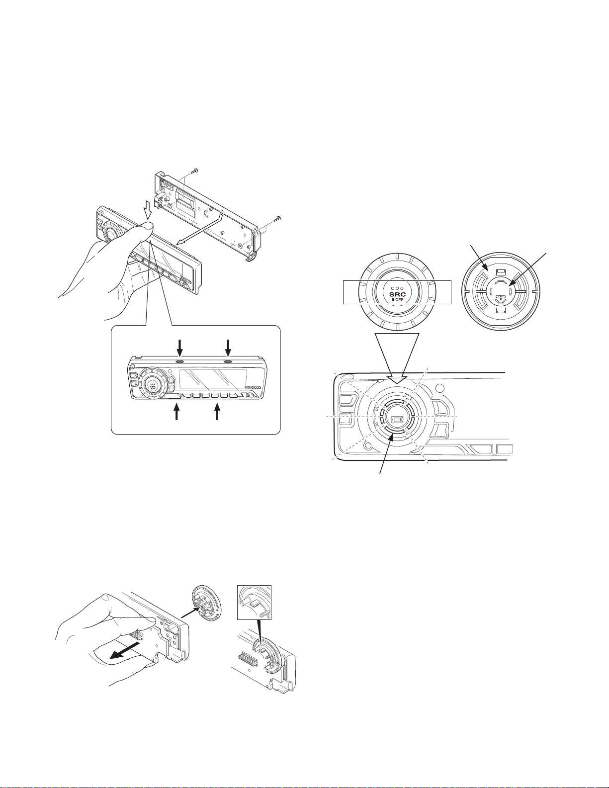
DISASSEMBLY FOR REPAIR
How to Disassemble (PANEL ASSY)
1)Remove four screws (A).
2)While holding the section (B) indicated with arrows, pull and
remove PANEL ASSY.
x2
A
A
B
B
How to install knob (SRC)
1)Place knob (F) and knob (G) in the positions indicated in
the diagram below.
2)While keeping these positions, use a piece of adhesive tape
(H) to hold knobs in position, as shown in the diagarma.
3)Set the rotary (J) position as shown in the diagram.
4) While keeping the letters “SRC” horiz ontally in position, set
it to the rotary on the panel.
5)Remove the adhesive tape (H).
x2
F
G
H
B
3) Pull SWITCH UNIT (C) as indicated in the diagram and remove knob (D).
(The knob (D) is attached to the rotary with hook (E) and it
is not possible to remove hook (D) only.)
C
B
D
E
J
3
KRC-597/597Y
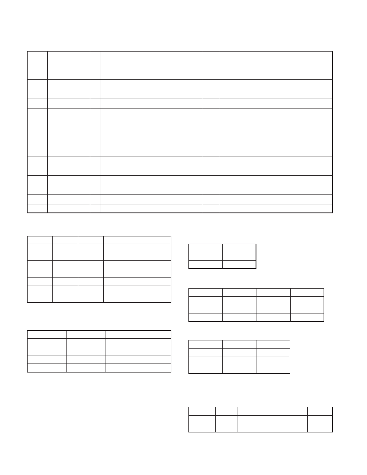
COMPONENTS DESCRIPTION
● SYNTHESIZER UNIT (X14-9182-71)
Ref. No. Application / Function Operation / Condition / Compatibility
IC1 System µ-COM Controls FM/AM tuner, the changer, cassette mechanism, Panel, volume and tone.
IC2 E.Vol & N.C.MPX Controls the source, volume, tone and FM multiplex detector.
Bu5V (5V), Audio8V (8V), FM+B (8V), AM+B(8V), P-CON, ANT-CON
IN OUT
EN1 ILLUMI
0V OFF
5V ON
IN OUT
EN2 AM FM A8V
IC3 Power Supply IC
0V OFF OFF OFF
2.5V OFF ON ON
5V ON OFF ON
IN OUT
EN3 ANT-CON P-CON
0V OFF OFF
2.5V OFF ON
5V ON ON
IC4 Power IC Amplifies the front L/R and the rear L/R to 50W or 47W maximum.
IC6 Muting logic IC Controls logic for muting.
IC7 RDS decoder
IC8 Reset IC “L” when detection voltage goes below 3.5V or less.
IC9 Equalizer amplifier Dolby-B, Metal-EQ, Equalizer the Tape sound (120µsec).
Sub motor control
IN SUB MOTOR
IN1 (-) IN2 (+)
IC 11 Sub Motor Driver
LLSTOP
LHCW
HLCCW
HHSTANDBY
Q1 Serge Detection
Q2 BACK-UP Detection “L” when B.u is present. “H” when B.u is absent or momentary power down is detected.
Q3 ACC Detection “L” when Acc is present.
“L” when the back-up voltage becomes more than 18V (momentary power down). “H” when the
back-up voltage becomes less than 18V.
4
KRC-597/597Y
COMPONENTS DESCRIPTION
Ref. No. Application / Function Operation / Condition / Compatibility
Q4 SW 5V ON when the base is “L”.
Q5
Q6 P-CON Detection “H” when P-CON output is short-circuit.
Q51 Main Motor SW q Outputs 14V when the base is “L”.
Q52 Main Motor SW w Q51 turns ON when the base is “H”.
Q53 Sub Motor AVR Output 3.6V when the base of Q4 is “L”.
Q54 MSTC SW ON when the base is “H”.
Q101 Composite signal buffer
Q151 DSI Driver
Q152 Panel 5V SW
Q201 Noise buffer
Q350 Pre Mute SW Drives the Pre Mute sw (Q351~354) when the base is “L”.
Q351 Pre Mute SW Mutes the Rear Lch when the base is “H”.
Q352 Pre Mute SW Mutes the Rear Rch when the base is “H”.
Power-Antenna “H” when P-ANT output is short-circuit (P.ANT OFF).
Detection “L” when FM/AM signal does not exist.
DSI lights when the base is “L”. DSI turns off when the base is “H”. DSI turns on and off when
panel is taken off.
When the panel is attached, the base goes “L”, turning the Tr ON to supply 5V to the panel.
When panel is taken off, panel 5Vcut off.
● SWITCH UNIT (X16-2502-70)
Ref. No. Application / Function Operation / Condition / Compatibility
IC1 LCD Driver Drives LCD
IC2 Remote Control IC Controls the unit
Q1,4 REMO ON SW The power supply of IC2 is turned on when base level goes “L”.
Q2 Key Illumination SW (Green) Lights Green key-illumination when base level goes “H”
Q3 Key Illumination SW (Red) Lights Red key-illumination when base level goes “H”
5

KRC-597/597Y
MICROCOMPUTER’S TERMINAL DESCRIPTION
● SYSTEM MICROCOMPUTER : MN101C49HNB (IC1 : X14)
Pin No. Pin Name I/O Application
1 VREF- GND for A/D
2F REEL I Reel pulse FWD C mechanism reel pulse output FWD. Vth=2.5V
3R REEL I Reel pulse REW C mechanism reel pulse output REW. Vth=2.5V
4 S-METER I K3I TUNER S-METER
5 IFC-OUT I IF COUNT 0V or 5V
6 NOISE I FM noise DET terminal
7 PHONE I PHONE DET terminal
8
9 GND GND
10 VREF+ VCC for A/D
11 VDD µ-com main VCC
12 MAIN OSC1 Main oscillation input 8.38MHz
13 MAIN OSC2 Main oscillation input
14 VSS µ-com main GND
15 SUB OSC1 32.768kHz oscillation input
16 SUB OSC2 32.768kHz oscillation input
17 GND GND External ROM
18 LX-DATAM O DATA output terminal to CH Retain last
19 LX-DATAS I DATA input terminal from CH
20 LX-CLK O CLK input/output terminal with CH
21 FLASH READ O
22 FLASH WRITE O
23 FLASH CLK O
24 BEEP O Beep for internal amp
25 PANEL-DET I DET terminal for panel DET or no panel DET Panel no DET : L, Panel DET : H
26 REMO I Remote control input
27 R-CLK I CLK for RDS decoder No destination : Output fixed to L
28 LX-REQS I Request input from CH Request DET : L
29 B.U-DET I Momentary power dropped detection
30 EJECT I Tape eject L : KEY input
31 KEY-REQ I Communication request from LCD driver L : KEY input
32 VDD I VDD
33 RESET I Reset
34 EQ MUTE O EQ MUTE
35 DOLBY O B NR ON/OFF
DCDET RESERVE
ITurn lLLUMI down when DE DET is not used DC offset DET terminal for P-IC
Truth Value
Table
Processing Operation Description
TEL MUTE : 1V or less NAVI MUTE : 2.5V or less
1V or less, 2.5V or more and NAVI MUTE only for J
BU DET : L, B.U-DET (momentary power dropped) : H
During TAPE PLAY : L, During TAPE FF/REW : H,
In other modes than TAPE : H
B NR ON : H, B NR OFF : L,
In other modes than TAPE : Retain value
6

KRC-597/597Y
MICROCOMPUTER’S TERMINAL DESCRIPTION
Pin No. Pin Name I/O Application
36 MUSIC I Tape between-music DET Music signal DET : L, Music signal no DET : H
37~40 NC O
41 VDD I VDD
42 L DATAS O TXD for LCD
43 L DATAL I RXD for LCD
44 L CLK O CLK for LCD
45 PLL DATA I/O TUNER I2C SDA
46 NC O
47 PLL CLK I/O TUNER I2C SCL
48~50 NC O
51 PANEL 5V I/O Panel 5V ON/OFF Panel DET, ACC ON : L
52, 53 NC O
54 VOL A I Rotary encoder input Refer to timing chart.
55 VOL B I Rotary encoder input Refer to timing chart.
56 DSI O
57 NC O
58 FILP-DET I 14seg collapsible DET
59 L CE O LCD driver CE
60 NC O
61~63 TYPE0~TYPE2 I Destination setting r
64 NC O
65 ST TYPE0 I For OEM r
66 ST TYPE1 I For OEM r
67~69 NC O
70~72 MODE1~MODE3 I Cassette mechanism mode DET q
73 MOTOR O Cassette mechanism main motor During motor operation : H, During motor stop : L
74 SUB+ O Cassette mechanism sub motor w
75 SUB- O Cassette mechanism sub motor w
76 R QUAL I RDS QUAL
77 R DATA I RDS DATA
78 LX-MUTE I MUTE request from CH H : MUTE ON, L : MUTE OFF
79 LX-CON O Control output to CH ON : H, OFF : L
80 LX-REQM O Request output to CH Request DET : L
81 LX-RST O Reset for CH
82 MUTE O MUTE
83 AFS O Constant switching terminal when noise DET
84 IC2 SDA I/O SDA for EVOL
85 IC2 SCL I/O SCL for EVOL
86 P-MUTE O POWER IC MUTE output terminal
EJECT KEY ILLUMI, GUIDE ILLUMI, DSI control terminal
Truth Value
Table
Processing Operation Description
ILLUMI : L, No ILLUMI : H
Normal L, 400msec or more after system reset H, then L
During FM seek and AF search : L, During reception : H
When POWER OFF : L, ALLOFF : L, TEL MUTE : L
7
KRC-597/597Y
MICROCOMPUTER’S TERMINAL DESCRIPTION
Pin No. Pin Name I/O Application
87 P-STBY O POWER IC STBY output terminal When POWER IC ON : H, OFF : L
88 SVR O POWER IC SVR control terminal Momentary power dropped : H
89 ACC-DET I ACC DET ACC DET : L, ACC no DET : H
90 PCON-DET I P-CON output DET P-CON DET : L
91 NC O Output fixed to L when P-ANT no DET
92 MS MODE O Tape between-music DET
93 F/R O Tape EQ input switching
94 METAL O Tape metal ON/OFF
95 DAVSS
96~98 EN2~EN1 O Power IC control e
99 SW5V O SW5V control
100 DAVDD Reference power supply for D/A
Truth Value
Table
Processing Operation Description
During TAPE PLAY : H, During TAPE FF/REW,
and other than TAPE mode : L
FWD input : L, REV input : H,
Other than TAPE mode : Retain value
NORMAL : H, METAL : L,
Other than TAPE mode : Retain value
Truth Value Table q
MODE 1 MODE 2 MODE 3 Condition
LHHEject
HLHSTBY
LLLREW
LLHFF
HLLREV Play
HHLFWD play
HHHPosition other than above
Truth Value Table w
SUB MOTOR + SUB MOTOR - Condition
LLStop (During Power OFF)
LHFWD (Loading direction)
HLREV (Eject direction)
HHStop (During Power ON)
Truth Value Table e
EN1 Control
EN1 ILL
L OFF
HON
EN2 Control
EN2 AUDIO 8V AM 8V FM 8V
L OFF OFF OFF
MONOFF ON
HONONOFF
EN3 Control
EN3 P-ANT P-CON
L OFF OFF
M OFF ON
HONON
✽ H=5V M=2.5 L=0V
Truth Value Table r
MODEL TYPE0 TYPE1 TYPE2 ST TYPE0 ST TYPE1
KRC-597 L H H L L
KRC-597Y L H H L L
8

TEST MODE
KRC-597/597Y
1. How to enter the test mode
• While holding the Preset 1 and Preset 3 keys, reset the unit.
2. How to exit from the test mode
• Reset the unit, momentary power down, ACC OFF, po w er
OFF, and Panel detached.
•(Note) The test mode cannot terminated by Panel is fall
down.
3. Initial status in the test mode
• Sources :All OFF.
•Display :All segments are lit.
•Volume :-10 dB (displayed as 30)
• Loudness :OFF
• CRSC :OFF regardless of the presence of
switching function.
• SYSTEM Q : Flat.
• BEEP : When pressing any keys, the buzzer
generates a beep at any time.
• DISPLAY TYPE: TYPE A
4. RDS automatic measurement
• An addition to disposal of substitute for visual check PS
display as usual production lines.
• P-CON ter minal is OFF by force, when received the PS
data and in case of corrobaration PS display is
“RDS_TEST”. (“_” is mean blank.)
• This disposal is test mode only.
• P-CON is switching the source or return with power on→off.
7. Test mode specifications of the cassette
receiver
•BLANK SKIPP : OFF
8. Audio-related specifications
•A short press of the Q key initiates the audio adjustment
mode.
• Pressing the ✽ key on the remote initiates the audio
adjustment mode.
•Fader is selected to the initial item.
• Continuous holding of a remote control key is inhibited.
• Bass, Middle and Treble are adjusted in 3 steps of -8/0/+8
with the Track Up/Down keys.
• Balance is adjusted in 3 steps of L15/0/R15 with the Track
Up/Down keys.
•Fader is adjusted in 3 steps of F15/0/R15 with the Track
Up/Down keys.
•Volume Offset is adjusted in 2 steps of -8/0 with theTrack
Up/Down keys.
9. Menu-related specifications
•A short press of the MENU key initiates the Menu mode.
Except, tape source is usually press and hold 1 second to
enter the menu mode and short press initiates turn over.
• Pressing the DNPP/SBF key on the remote initiates the
Menu mode.
• Continuous holding of a remote control key is inhibited.
• Contrast is adjusted in 3 steps of 0/5/10 (5x7dot), 0/4/7
(14seg) with the Track Up/Down keys.
5. Special display in Tuner mode
When any of the following messages is displayed in Tuner
mode, the front end may be abnormal.
• “TNE 2P NG”: The EEPROM is set to the default (unstable
values) because the F/E was shipped without passing
through the adjustment process, etc.
• “TNCON NG”: Communication with the F/E is not possib le.
6. Forced switching of K3I
• Each press of the Preset 6 key in Tuner mode should switch
K3I from AUT O → Forced Wide → Forced Middle → Forced
Narrow → AUTO. The initial status is AUTO and the display shows these modes as follows.
•AUTO:FMA
•Forced Wide :FMW
•Forced Middle : FMM
•Forced Narrow : FMN
10. Backup current measurement
•When the unit is reset while ACC is OFF (i.e. by turning
Back-Up ON), the MUTE terminal goes OFF in 2 seconds
in place of 15 second.
9
 Loading...