

KENWOOD KRC-31Y, KRC-36, KRC-366L, KRC-37, KRC-37Y SERVICE MANUAL
...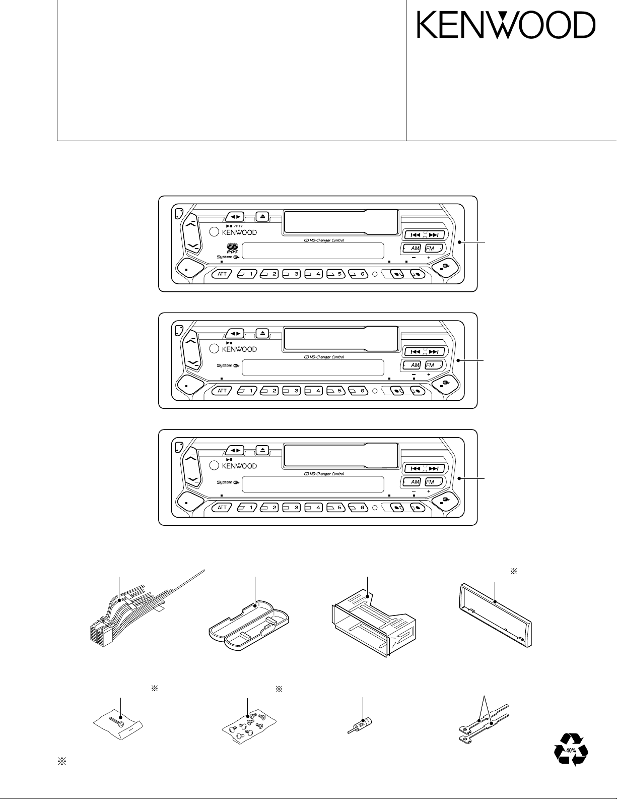
CASSETTE RECEIVER
KRC-31Y/36/366L/37/37Y
/391/394/394Y/466R
/4904Y
SERVICE MANUAL
Mechanism extension cord : W05-0477-00 (7P), W05-0609-00 (10P)
© 2002-10 PRINTED IN JAPAN
B51-7986-00 (N) 2139
KRC-36/37/37Y
/391/394
/394Y/466R
KRC-31Y/366L
KRC-4904Y
SRC
SRC
SRC
Panel assy
KRC-391:
(A64-2538-02)
KRC-XXXX
OFF
LOUD SCRL SCAN REP T.CALL M.RDMB.S/RDM MENU TI VOL ADJCLK
45Wx4
DISC
AUD
KRC-36:
(A64-2541-02)
KRC-466R:
(A64-2941-02)
KRC-394/394Y:
(A64-2945-02)
KRC-37/37Y:
(A64-2947-02)
Panel assy
KRC-XXXX
OFF
OFF
LOUD SCRL SCAN REP T.CALL M.RDMB.S/RDM MENU AUTO AMECLK
KRC-4904
LOUD SCRL SCAN REP T.CALL M.RDMB.S/RDM MENU AUTO AMECLK
45Wx4
DISC
AUD
WIDE BAND
45Wx4
DISC
AUD
KRC-366L:
(A64-2942-02)
KRC-31Y:
(A64-2946-02)
Panel assy
(A64-2948-02)
DC cord
(E30-4792-05)
Screw set
(N99-1610-15)
Plastic cabinet assy
(A02-1486-13)
Screw set
(N99-1719-05)
Depends on model. Refer to the parts list.
Mounting hardware assy
(J21-9716-03)
Antenna adaptor
(T90-0523-05)
Escutcheon
(B07-)
Lever
(D10-4589-04)
x2
KRC-31Y/36/366L/37/Y
FM ANT
AM ANT
RF GND
FM+B
AM+B
AM LO/DX
FM LO/DX
IF SELECT
RDS OUT
FM SD OUT
REQUEST
K2I-VTH
VCO-GND
FSD OUT
FM DET OUT
AM DET OUT
IF GND
COMMON+B
P-ON 5V
DIG GND
PLL DATA
PLL CLK
PLL CE
HI UP ADJ
FM+B
AM+B
A8V
SW5V
LO/DX
SD
S-METER
PLL-DATA
PLL-CE
SW5V
ACC-DET
BU-DET
SCL
MUTE
SDA
EN1
EN2
EN3
PANEL
RESET
DSI
CH MUTE
NOISE
DATA H
DATA C
REQ H
REQ C
CH RST
CH CON
CH CLK
Rch
COM
Lch
TAPE L/R
MP IN
AFS
QUAL
AM
MPX
OUT RR
OUT LR
OUT RF
LEVEL
SCL
SW5V
SDA
SCL
SDA
OUT LF
STBY
MUTE
SMUTE
5
10
BU5V
AFS
R QUAL
R CLK
R DATA
BU5V
REMO
SW5V
GREEN
RED
BU5V
PHONE
BEEP
SVR
P-MUTE
P-STBY
SVR
AC GND(BEEP)
TAPE L/R
PLL-CLK
SW5V
L-RES
L-CLK
L- DATA S
L- DATA L
MUSIC
EQ-MUTE
MS-CONT
MUSIC
EQ-MUTE
MS-CONT
FWD/REV
PACK IN
M-STBY
T-MODE
T-END
L-CE
340mV
SUB+
SUB-
Rch
Lch
PACK
T-END
M-STBY
T-MODE
FWD
REV
AUDIO
8V
MOTOR
BU14V
SW5V
IN
PLAY HEAD
SW5V
BU14V
BU5V
BU14V
EN1
EN2
EN3
P,CON
ILLUM
B.U.5V
AM+B
AUDIO
FM+BFM+B
AM+B
AUDIO 8V
AUDIO 8V
AUDIO 8V
BU5V
SW5V
TAPE
CD-CH
AM
FM
: 1719mV
: 3424mV
: 550mV
: 1727mV
TAPE
CD-CH
AM
FM
: 1786mV
: 3546mV
: 850mV
: 1345mV
AM : 160mV
FM : 213mV
CD L/R
1200mV
BU14V
CD L/R
8
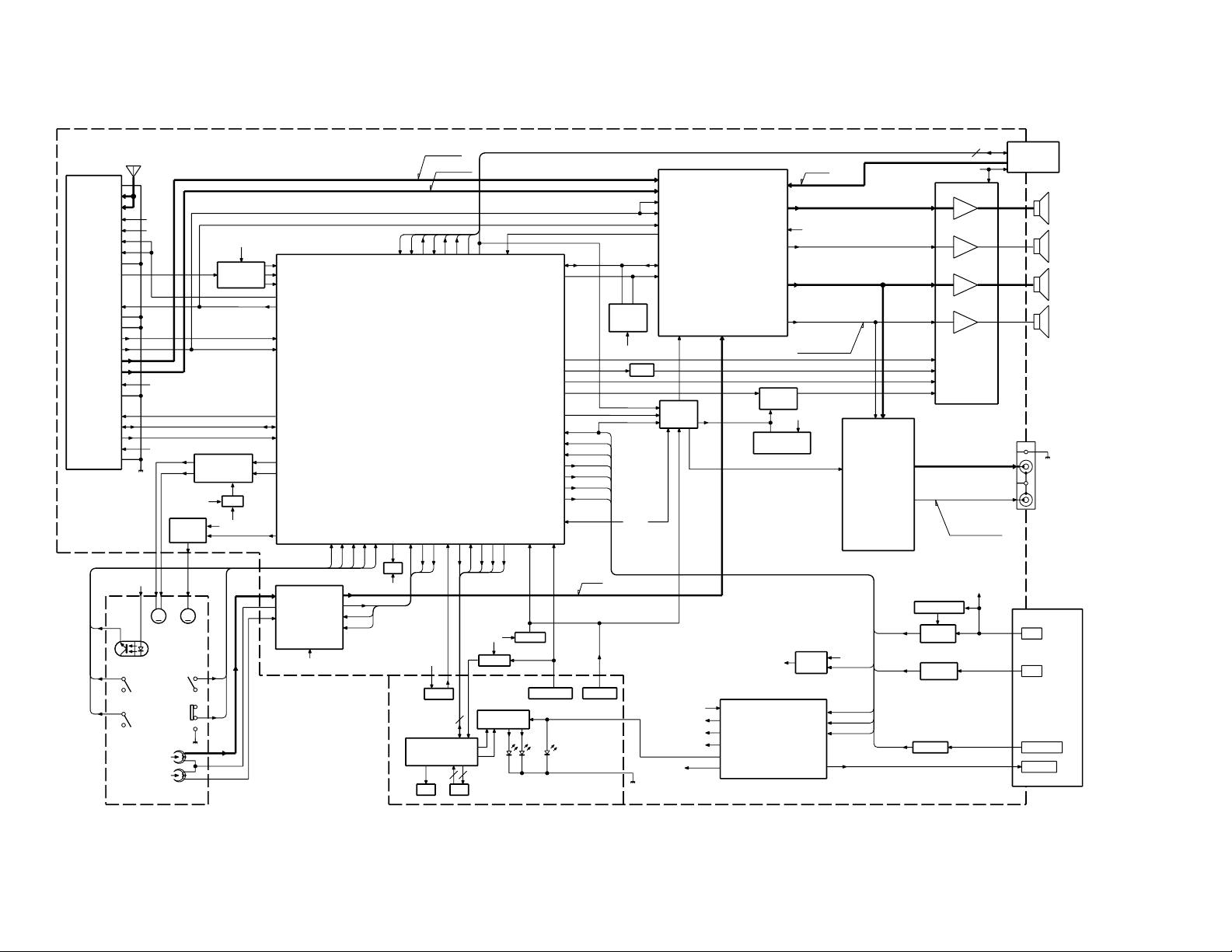
RDS
ANT.
DECODER
SYSTEM u-COM
KEY
PAN 5V
MUTE
E2PROM
EQ AMP
CD ISO AMP
E-VOL
LCD DRIVER
LCD
DSI
REMO
RST SWPAN IN SW
GREEN
RED or
RST IC
TEL DET TEL MUTE
DRIVER
MAIN
SUB
AVR
SW5
B.U. DET
SURGE-DET
B.U.
ACC
P-CONT
DC CONNECTOR
REGULATOR
ACC DET
J2
VOLTAGE
MUTE
PRE
R-Lch
R-Rch
AMP
SVR
MUTE
THERMO
PROTECTION
FRONT Lch
FRONT Rch
REAR Lch
REAR Rch
IC4
J4
POWER IC
TDA7386
CD/MD
CHANGER
SP OUT
J5
PRE OUT
IC10
SUB MOTOR
DRIVER
MOTOR
DRIVER
IC1
IC2
IC12
IC9
IC2
IC1
IC11
IC7
IC8
Q2,3
IC6
TUNER
(X16)
(X14)
MM
TAPE MECHA
2
/391/394/Y/466R/4904Y
BLOCK DIAGRAM
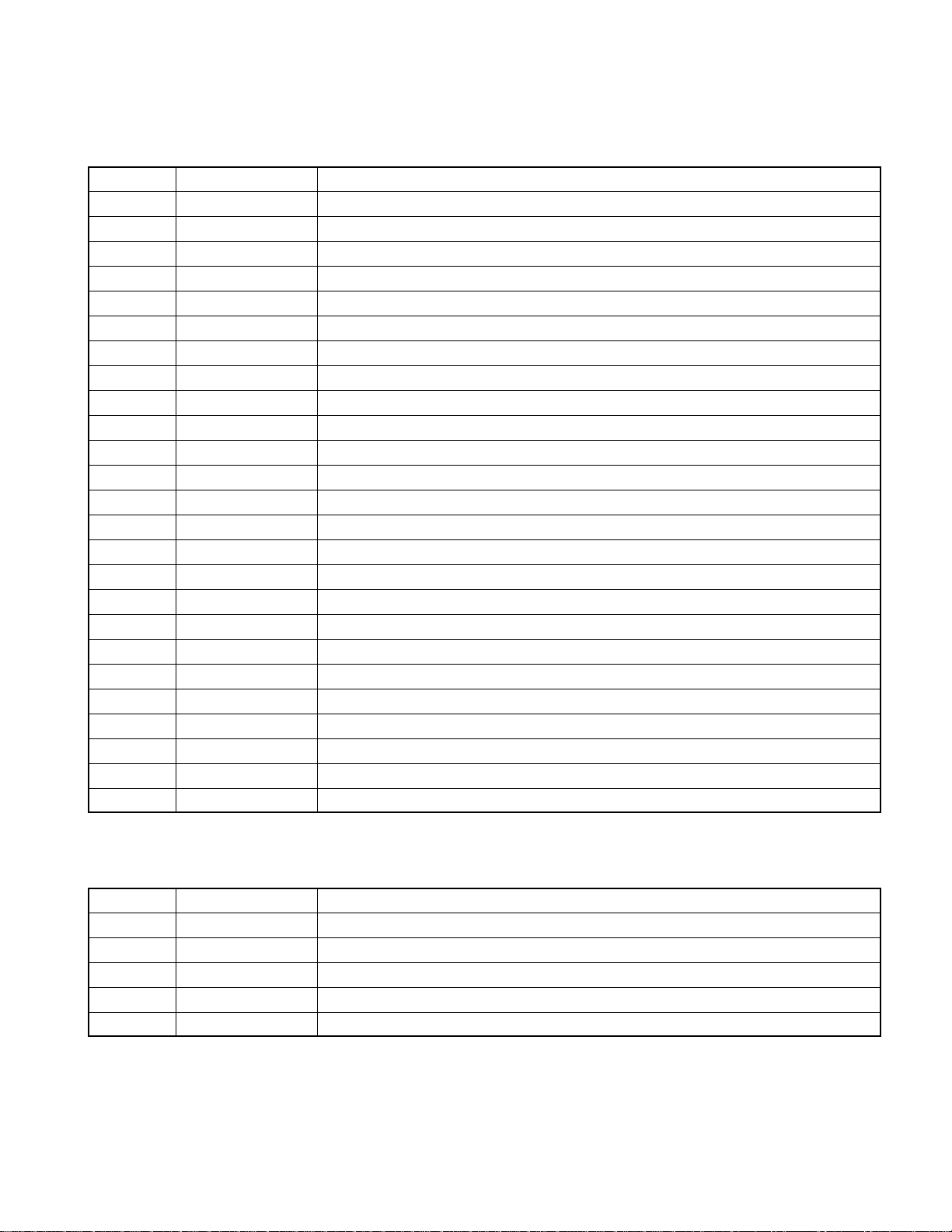
KRC-31Y/36/366L/37/Y
/391/394/Y/466R/4904Y
COMPONENTS DESCRIPTION
● SYNTHESIZER UNIT (X14-689x-xx)
Ref. No. Function Operation
IC1 System µ-com
IC2 E-volume
IC4 Power amplifier Speaker output.
IC6 RDS decoder
IC7 Power IC
IC8 Mute control logic 3 input NOR gate x 3.
IC9 Equalizer amplifier For full logical cassette mechanism control.
IC10 Sub motor driver For full logical cassette mechanism sub motor driver.
IC11 Reset IC Detection voltage below 3.0V.
IC12 EEPROM
Q1 P. CON detection Detects P.CON voltage.
Q10 Backup detection Detects the backup voltage.
Q11 Surge detection Detects surge voltage.
Q20 ACC detection Detects ACC voltage.
Q40 Preout mute driver Mutes when the base terminal voltage level becomes “L”.
Q50 5V SW Works when the base terminal voltage level becomes “L”.
Q101 DSI SW LED for DSI works when the base terminal voltage level becomes “H”.
Q151 Panel 5V SW Works when the base terminal voltage level becomes “L”. Supplies VDD to panel.
Q201 Noise detection Detects noise.
Q221~224 Preout mute Mutes when the base terminal voltage level becomes “H”.
Q251 Power IC SVR SW Discharges the capacitor’s voltage of SVR terminal after the base terminal voltage becomes “H”.
Q301 Local seek SW Changes to the local seeking after the base terminal voltage becomes “H”.
Q501 Motor driver AVR Works when the base terminal voltage becomes “H”. Supplies the power to the motor driv er.
Q551 Main motor SW Works when the base ter minal v oltage becomes “L”.
Q552 Main motor SW Works when the base ter minal v oltage becomes “H”.
● SWITCH UNIT (X16-1532-7x)
Ref. No. Function Operation
IC1 LCD driver
IC2 Remote sensor
Q1 Key scan SW Receives key signal when the base terminal voltage becomes “L”.
Q2 Key illumination SW Key illumination color becomes green when the base terminal voltage becomes “H”.
Q3 Key illumination SW Key illumination color becomes red when the base terminal voltage becomes “H”.
3
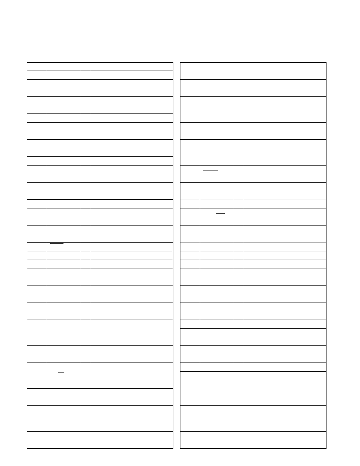
KRC-31Y/36/366L/37/Y
/391/394/Y/466R/4904Y
MICROCOMPUTER’S TERMINAL DESCRIPTION
● Microcomputer : UPD780058GCxxx (X14 : IC1)
Pin No. Pin Name I/O Function / Operating Condition
1 DSI O DSI control.
2 PANEL I Panel detection. “L” : Panel exists
3- -4 AVSS - GND.
5 L-RST O LCD driver reset.
6 L-CE O LCD dr iver chip enable.
7 AVREF1 I Reference voltage.
8- -9 PLL-DATA I/O Front-end communication data.
10 PLL-CLK O Front-end communication clock.
11 L-DATA L I LCD dr iver communication data.
12 L-DATA S O LCD driver communication data.
13 L-CLK O LCD driver communication clock.
14 R-DATA I RDS data.
15 R-QUAL I RDS QUAL.
16 CH-DATA C I Changer communication data.
17 CH-DATA H O Changer communication data.
18 CH-CLK I/O Changer communication clock.
19 M-STBY I
20 T-END I
21 ACC-DET I ACC detection.
22 BU-DET I Backup detection.
23 IC2 TYPE 0 I For service. “L” : Normally
24 IC2 TYPE 1 I For service. “L” : Normally
25 TYPE 0 I Destination discrimination.
26 TYPE 1 I Destination discrimination.
27 TYPE REF O
28 MOTOR O
29 PLL-CE O
30 SD I
31 ASF O
32 LO/DX O
33 VSS1 - GND.
34 P-MUTE O Power amplifier muting.
35 SVR O SVR control.
36 - - 37 IC2-SCL O E-volume communication clock.
38 IC2-SDA I/O E-volume communication data.
39 MUTE O Muting control.
40 P-STBY O Power amplifier standby.
4
Cassette tape standby detection.
“H” : Standby
Tape end detection. “H” : Run, “L” : Stop
Reference voltage for destination
and service.
Cassette mechanism motor.
“H” : ON, “L” : OFF
Front-end communication ship enable.
Station detection. “H” : Station exists,
“L” : Station does not exist
Noise detection time constant switch.
Local seeking switch. “H” : LO, “L” : DX
Pin No. Pin Name I/O Function / Operating Condition
41 P. CON-DET I P. CON short-circuited detection.
42 CH-CONT O Changer control.
43 - - 44 CH-REC H O Changer request.
45~47 - - 48 EN2-1 O Power supply IC control.
49 EN2-0 O Power supply IC control.
50 BEEP O Buzzer.
51 EN3 O Power supply IC control.
52 EN1 O Power supply IC control.
53 SW 5V O P. ON 5V control. “H” : OFF, “L” : ON
54 MUSIC I
55 MS-CONT O
56 EQ-MUTE O
57 FWD/REV I
58 SUB+ O Sub motor control.
59 SUB- O Sub motor control.
60 RESET I System reset.
61 REMOTE I Remote control.
62 R-CLK I RDS clock.
63 CH-REQ C I Changer request.
64 PACK-IN I Cassette tape pack-in detection.
65 KEY-REQ I Key signal detection.
66 - - 67 VSS0 - GND.
68 VDD1 - VDD.
69 X2 - Main system clock.
70 X1 I Main system clock.
71 IC - 72 - - 73 XT1 - VDD.
74 VDD0 - VDD.
75 AVREF 0 I Reference voltage.
76 S-METER I
77 T-MODE I Cassette tape mode detection.
78 PHONE I
79 NOISE I Noise detection during FM mode.
80 AV CONT O reference voltage.
Tape signal detection. “H” : Signal
does not exist, “L” : Signal exists
tape advanced sensitivity control.
“H” : Play, “L” : FF/REW
Cassette tape muting. “H” : ON, “L” : OFF
Cassette tape runing direction detection.
“H” : FWD, “L” : REV
SD detection.
“H” : SD exists, “L” : SD does not exist
Navi mute : Over 2.5V,
Tel mute : Less tha 2.5V
KRC-31Y/36/366L/37/Y
/391/394/Y/466R/4904Y
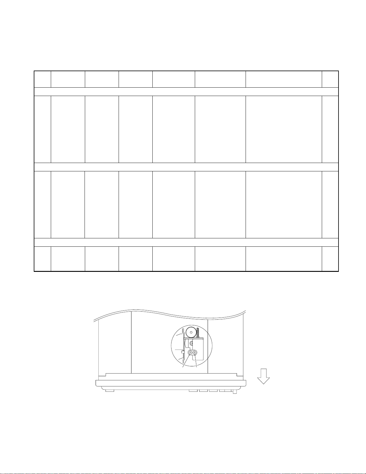
ADJUSTMENT
BALANCE/FADER/BASS/TREBLE : CENTER
T. ADV/METAL/DOLBY NR/AUTO : OFF
No. Item Input Output Receiver Alignment Align For Fig.
Settings Settings Settings Points
FM Section
While holding preset “1” key,
press and hold preset “6” key
1SD
AM Section
(1) SD
Cassette Deck Section
1 AZIMUTH
98.1MHz
0 dev
35dBµ
(ANT input) (7 seg model :
990kHz
0% mod
35dBµ
(ANT input) (7 seg model :
TCC-153 Head azimuth screw
10kHz
– FM
– AM
SP OUT TAPE PLAY
TEST MODE : ON
98.1MHz
TEST MODE : ON
990kHz
Preset “1” key, and “ADJ OK” is good.
preset “6” key “ADJ NG” is not good.
Preset “1” key, and “ADJ OK” is good.
preset “6” key “ADJ NG” is not good.
(FWD/REV)
for a few seconds.
“1111” is good.
“0000” is not good.)
While holding preset “1” key,
press and hold preset “6” key
for a few seconds.
“1111” is good.
“0000” is not good.)
Adjust so that output level in
playing “FWD” and “REV” (a)
becomes maximum each.
TEST MODE : ON While holding the “FM” key and preset “6” key, reset the unit.
TEST MODE : OFF Reset the unit.
(a) AZIMUTH
FWD
REV
PANEL FRONT
5
A B C D E
0
5
A
M
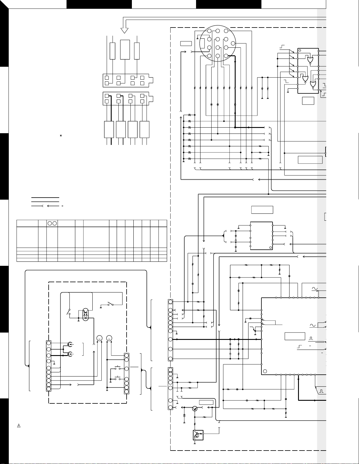
SYNTHESIZER UNIT (X14-689X-XX)
CLK
REQ C
R411 100
R408 4.7K
C404 0.01
R415 100K
7
5
6
R413 100K
R414 100K
R412 100K
63
18
17
+B
39
5V
0V
5V
0V
0V
IC8
1
2
3
4
5
6
7
GND
MUTE
DRIVE
PREOUT
MUTE DRIVER
VDD
14
13
12
11
10
9
8
IC1 :
1
IC2 : TDA7407D
IC4 :
IC6 : TDA7479D
IC7 : TDA3682ST
IC8 : HD74HC27FP
IC9 : HA12221F
IC10
IC11
IC12
Q1,301 : DTC124EUA or
Q10,11,20,101,201
Q40 : DTA124EUA or
Q50 : 2SA1036K
Q151 DTA114YUA or:
2
Q223,224 : DTC143TUA or
Q251 : DTC114YUA or
Q501 : 2SD1760
Q551 : 2SB1443
Q552 : DTC114EUA or
D1 :
D2,3 : 1GWJ43 (TPB5)
D4,551 : AM01Z or
D10,11,401,402
D20 : MA4051 (N) -M
3
D40,101,251-253
D102
D153,154,157,159-161,
∗
TDA7386
LB1930M
:
S-80835CNNB
:
: BR24C01AF
UN5212
2SC4081 or:
2SD1819A
UN5112
UN5114
UN5216
UN5214
UN5211
1N5393G-M6 or
S2V20 A
ERA15-01
: MA4068 (N) -M
MA4047-M or:D30
HZS5B1
: 1SS133
: B30-1567-05
403,404,407,409-411
MA4062-L or:
HZS6C1
ACC
RED
BLK
8
A-PART
75
B-PART
7B531
GRN
GRN/BLK
REAR. L
(E30-4792-05)
BATT
P.CONT OUT
ANT.CONT
BLU/WHT
WHT/BLK
FRONT. L
YEL
31
GRY
GRY/BLK
FRONT. R
64
6248
WHT
DC1
2
VIOL
A
VIOL/BLK
REAR. R
CH-IN
B.U.
+B
+B
D404
D407
D401
D402
D403
D409
D410
D411
GND
CON
REQ H
R404 100
R405 4.7K
44
J4
159
2
43812
MUTE
S GND
R403 4.7
R406 4.7K
+
C403 100u10
42
10
13
7611
Lch
Rch
RST
DATA H
DATA C
R402 10
C402 1u50+C401 1u50
R407 4.7K
R409 4.7K
16
R401 10
+
R410 100
SIGNAL LINE
GND LINE
B LINE
A1
CB
YES
X86-3512-70
NO
X86-3512-72
NO
X86-3512-70
NO
X86-3512-70
X86-3512-70
CASSETTE MECHANISM
(D40-1150-05)
YES
UPD780058GC418
NO
UPD780058GC426
UPD780058GC418
NO
UPD780058GC426
UPD780058GC418NONO
PACK
IC1
MODE
R111C308
YES
NO
NOYES
YES
FWD/REV
FWD/REV
R112
NO
YES
YES
R113
YES
YES
YES
NO
NO
4
5
(X14-689X-XX)
MODEL NAME
KRC-394Y (E)
KRC-37Y (E)
KRC-394 (E)
KRC-37 (E)
KRC-36 (E)
KRC-391 (E)
KRC-4904Y (E)
KRC-31Y (E)
KRC-366L (M)
KRC-466R (M)
+B
UNIT
No.
2-70
2-72
2-71
0-22
0-21 YES YES YES
PACK
M1M2
MAIN
HD1
+2V
SUB
M
M
7
6
T-END
5
STBY
4
3
2
1
PLAY
10
HEAD R
9
HEAD COM
8
HEAD L
7
6
GND
F/R
PACK IN
SUB(+)
SUB(-)
MODE+B
MODE
6
5
4
3
2
1
HEAD
Rch
Lch
+2V
CAUTION : For continued safety, replace safety critical components only with
manufacturer's recommended parts (refer to parts list).
Indicates safety critical components. To reduce the risk of electric shock,
leakage-current or resistance measurements shall be carried out (exposed
7
parts are acceptably insulated from the supply circuit) before the appliance is
returned to the customer.
• DC voltages are as measured with a high impedance voltmeter. Values may
vary slightly due to variations between individual instruments or/and units.
M+R
GND
T-END
STBY
GND
R114
NO
NO
NO
YES
YES
R146R118
YESYES
NO NONO
YESNONO
NO
YES YES
HEAD COM
Q301
YES
YES
NO
YES
MODE
MODE+B
SUB(-)
SUB(+)
PACK IN
GND
HEAD L
HEAD R
GND
STBY
T-END
GND
M+B
CN1
F/R
CN2
1
2
3
4
5
6
7
8
9
10
1
2
3
4
5
6
7
R533 470C532 0.01
R534 100K
R536
22K
R535
9
7
19
R556 470
R554 470
20
D551
Q551
1K
R552
470
R531
R551 10K
1/2W
10K
10K
Q552
MOTOR
+2V
+B +B
SUB MOTOR
DRIVER
IC10
6
0V 0V
PGND
7
7.6V
7
+5V
77
470
64
57
9
+B28
C511
1500P
C512
1500P
R513
C513
150
22u6.3
OUT2
8
NC
C533C534
9
7.6V
OUT1
10
NC
0.22 0.22
330K 5.1K
C516
R516
12K
0.01
+
C514
22u6.3
150
R514
3.8V
C509
1u50
+
0V
3.8V
15K
R511
3.8V
15K
R512
3.8V
+
C515
0.01
R517 R519
330K 5.1K
R515
12K
5
SGND
4
5.0V
IN2
IN1
NC
VCC
R520R518
31
NFI (R)
32
R IN (R)
33
RIP
34
F IN (R)
35
36
37
F IN (L)
38
V REF
39
R IN (L)
40
NFI (L)
58
3
5.0V
59
2
1
7.7V
+B
4.3K
R522
C518
0.1u50
3.8V
3.8V
302928272625242322
D IN (R)
M-OUT (R)
EQ OUT (R)
3.8V
EQUALIZER
AMPLIFIER
M-OUT (L)
RQ OUT (L)
D IN (L)
1
2
345
3.8V
3.8V
+
C517 0.1u50
4.3K
R521
+
IC9
3.8V
+B
3.8V
3.8V
RAI (R)
RAI (L)
PB OUT (L)
678
3.8V
PB OUT (R)
MS GV (R)
5V
S/R (MSGV)
0V
9
21
MA OUT
MS DET
5V
1V
MUSIC
MUTE
10
MS GV (S)
MSI
VCC
F/R
MTL
 Loading...