

Kenwood KRC-156 Service manual
©
2001-11 PRINTED IN JAPAN
B51-7855-00 (N)506
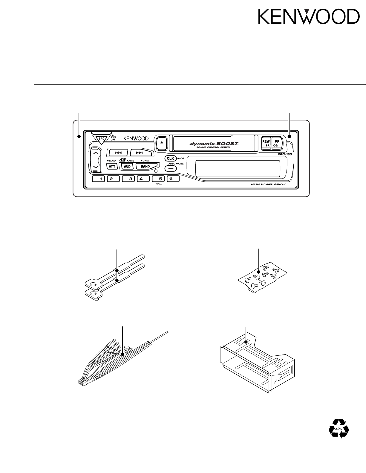
CASSETTE RECEIVER
KRC-165
SERVICE MANUAL
Mounting hardware assy
(J19-9491-13)
Screw set
(N99-1719-05)
Panel assy
(A64-2500-02)
Escutcheon
(B07-2188-02)
Lever
(D10-3031-04)x2
DC cord
(E30-4784-05)
KRC-165
2
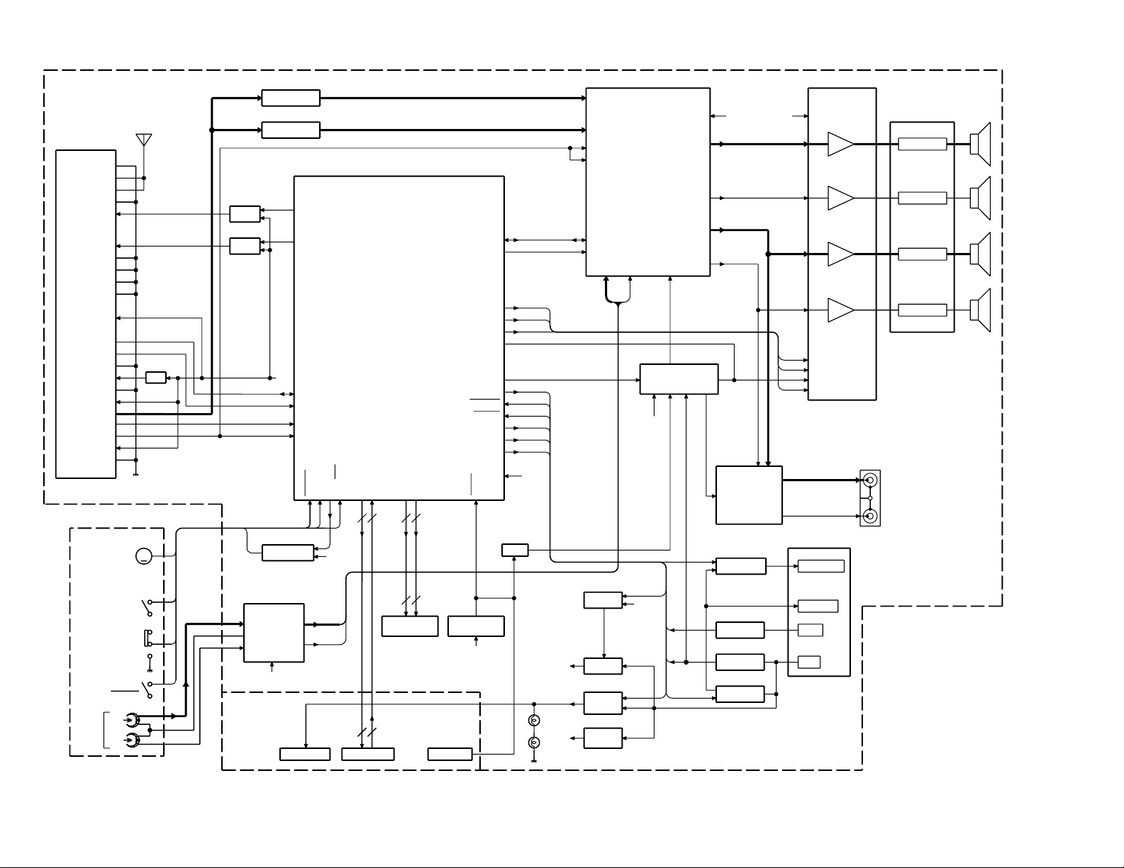
BLOCK DIAGRAM
IC1
KEY
MUTE
B.U DET
.
B.U
ACC
P-CONT.
MUTE
PRE
POWER IC
EQ. AMP
AMP
N.C.MPX
E-VOL.
FRONT Lch
FRONT Rch
REAR Lch
REAR Rch
J2
LED
CASSETTE MECHA
MAIN
IC5
1 Lch
2 Rch
PRE OUT
IC2
IC4,Q151
Q150,153
IC3
SP OUT
REAR
RST SW
RST IC
IC6
Q301
ACC DET.
P-CONT
.
ANT-CONT
J2
J5
FM+B
Q200,201
AM+B
Q202,203
5V
AM BPF
FM BPF
Q450,451
Q62
Q50
Q350-353
Q53
SW5V
Q54-57
8V
Q58-61
ILLUMI
BU5V
Q51,52
SYSTEM MI-COM
RST
Q370,371
ANT-CONT
7SEG LCD
ED1
FM ANT
AM ANT
RF GND
FM+B
AM+B
OSC GND
OSC GND
OSC GND
VT
PLL +B
IFC OUT
SDA
SCL
DIG GND
IF1+B
IF1 GND
S-METER
IF2 GND
SD
FM+B
PON
ACC DET
B.U DET
SCL
MUTE
SD
A
P CON
RESET
FWD/REV
MOTOR
Rch
COM
Lch
TAPE
MP IN
AM
MPX
OUT RR
OUT LR
OUT RF
LEVEL
SCL
SDA
OUT LF
STBY
MUTE
Rch
Lch
T-MUTE
FWD
REV
B.U
SMUTE
(FF/REW)
BU5V
AM+B
VDD 5V
PA
CK IN
ANT CON
BEEP
SVR
AMP. STBY
SVR
AC GND(BEEP)
Rch
Lch
TAPE :1681mV
AM :546mV
FM :1781mV
8V
RF GND
OSC GND
IF2 +B
AUDIO OUT
8V
S-METER
SD
PLL-SCL
PLL-SDA
HEAD
R
55.6mV
BU5V
B.U
B.U.5V
8V
BU5V
AM: 170mV
FM: 400mV
L
PACK
IN
PLAY
FF/REW
ILL
5
KS0-KS4
KI0-KI3
3
SEG1-SEG22
COM1-COM3
AMP. MUTE
8V
BU5V
(X16-)
M
A1
(X14-)
MOTOR SW
Q260,261
4
5
4
22
3
22
KRC-165
3
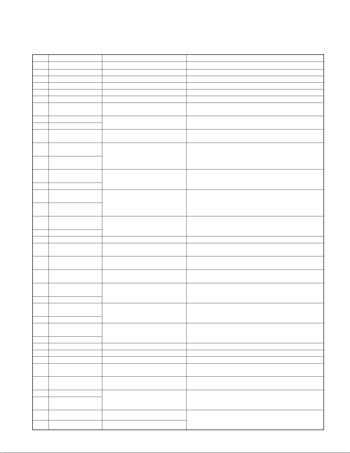
● SYNTHESIZER UNIT (X14-6860-20)
COMPONENTS DESCRIPTION
Ref.No.
Component Name Application/Function Operation/Condition/Compatibility
IC1 M38258MCD078FP System MI-COM. System control
IC2 TDA7400D E-VOL. & N.C. MPX Controls sound volume. Selects each source.
IC3 HD74HC27FP Mute logic 3-input NOR gate × 3
IC4 TDA7386 Power IC Amplifies power so that the speaker can drive audio signal.
IC5 LA3161 Equalizer amplifier Equalizer amplifier for cassette tape sound
IC6 PST9135NR Reset IC When BU 5V voltage is less than 3.5V, IC outputs Lo.
Q50 2SC2412K or 2SD601A
BACK-UP detection (Momentary power While BACK-UP is added, a base becomes Hi,
down detection) SW and Q50 is turned on.
Q51 2SB1443
BACK-UP 5V AVR
While BACK-UP is added, AVR outputs +5V.
Q52 2SC2412K or 2SD601A Q51 and Q52 is inverted Darlington connection.
Q53
DTA114YK or UN2114 or
KRA107S
P.ON 5V SW While a base becomes Lo, Q53 is turned on.
Q54
DTC144EK or UN2213 or
KRC104S
COM+B SW
While Q54's base becomes Hi, Q55 is turned on.
Q55
DTA124EK or UN2112 or Works during POWER ON mode.
KRA103S
Q56
2SA2057 or 2SB1548(P) or
While Q57's base becomes Hi, Q56 is turned on.
2SB1565(E,F) or 2SB1655(E,F)
COM+B AVR
Q57 2SC2412K or 2SD601A
Q56 and Q57 is inverted Darlington connection.
Q58
DTC144EK or UN2213 or
KRC104S
Illumination +B SW
While Q58's base becomes Hi, Q59 is turned on.
Q59
DTA124EK or UN2112 or Works during POWER ON mode.
KRA103S
Q60
2SA2057 or 2SB1548(P) or
2SB1565(E,F) or 2SB1655(E,F)
Illumination +B AVR
While Q61's base becomes Hi, Q60 is turned on.
Q61 2SC2412K or 2SD601A
Q60 and Q61 is inverted Darlington connection.
Q62 2SC2412K or 2SD601A ACC detection SW While ACC is added, Q62 is turned on.
Q150
DTC124EK or UN2212 or When BACK-UP detection SW or RESET SW or
KRC103S
Electric volume mute SW
MI-COM.'s mute works, a base becomes Hi, and Q150 is turned on.
Q151
DTC114YK or UN2214 or When POWER IC RESET is activated,
KRC107S
SVR discharge SW
a base becomes Hi, Q151 is turned on.
Q153
DTA124EK or UN2112 or When BACK-UP detection SW or RESET SW or
KRA103S
Pre-out mute driver
MI-COM.'s mute works, a base becomes Lo, and Q153 is turned on.
Q200
DTC124EK or UN2212 or
KRC103S FM +B SW
Q201 is turned on when Q200's base becomes Hi.
Q201 2SB1277(Q,R)
Works during FM reception mode.
Q202
DTC124EK or UN2212 or
KRC103S AM +B SW
Q203 is turned on when Q202's base becomes Hi.
Q203 2SB1277(Q,R)
Works during AM reception mode.
Q260
DTC114YK or UN2214 or
KRC107S Motor +B SW
When Q260's base becomes Hi, Q261 is turned on.
Q261 2SB1443
Works during TAPE mode.
Q301 DTA144EK or UN2113 RESET SW When a base becomes Lo, Q301 is turned on.
Q350 2SB1277(Q,R) P-CON. driver When Q353's base becomes Hi, Q350 is turned on.
Q351 2SA1037K P-CON. protection SW Works when P-CON is being short-circuited on GND.
Q352
DTA124EK or UN2112 or
KRA103S
P-CON. Protection inhibit SW Inhibits protection SW function when P-CON works momentary.
Q353
DTC114YK or UN2214 or Q353 is turned on when a base becomes Hi.
KRC107S
P-CON. SW
Works during POWER ON mode.
Q370 2SB1277(Q,R)
Q370 is turned on when Q371's base becomes Hi.
Q371
DTC114YK or UN2214 or ANT-CON. SW
KRC107S
Works during TUNER mode.
Q450 DTC143TK or UN2216 Pre-out mute SW (R Ch.)
When BACK-UP detection SW or CHANGER RESET SW or
MI-COM.'s mute works, a base becomes Hi,
Q451 DTC143TK or UN2216 Pre-out mute SW (L Ch.)
and Q450, 451 are turned on.
KRC-165
4
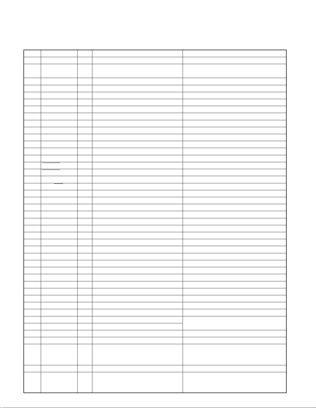
● Terminal Description (IC1 : X14-6860-20)
Pin No.
Pin name I/O Description
Processing Operation
1 I N.C. (Not used)
2 VL1 I
Positive power supply connection terminal 1
for LCD driver
3 KI0 I Key return input 0
4 KI1 I Key return input 1
5 KI2 I Key return input 2
6 KS0 O Key scan output 0
7 KS1 O Key scan output 1
8 KS2 O Key scan output 2
9 KS3 O Key scan output 3
10 S METER I S-meter input from the F/E
11 KS4 O Key scan output 4
12 BEEP O BEEP sound output
13 O N.C. (Not used)
14 MOTOR O Cassette motor on/off output Hi : Motor ON
15 FF/REW I FF/REW detection input Lo : FF/REW, Hi : PLAY
16 PACK IN I Cassette tape Pack-in detection input Lo : Pack-in
17 KI3 I Key return input 3
18 FWD/REV I FWD/REV mode detection input Lo : REV mode
19-25 O N.C. (Not used)
26 SD I SD input from the F/E Hi : Station detected
27 PLL CLK O Clock output to the F/E
28 PLL DATA I/O Data input/output with the F/E
29 IFC I N.C. (Not used)
30 AM+B O AM+B ON/OFF output Hi : during AM reception
31 FM+B O FM+B ON/OFF output Hi : during FM reception
32 SCK O Clock output to the E-VOL. IC
33 SDA I/O Data input/output with the E-VOL. IC
34 O Pull down to GND lines. (Not used)
35 RESET I RESET input Lo : System reset
36,37 O N.C. (Not used)
38 XIN - Main clock resonator connection terminal
39 XOUT - Main clock resonator connection terminal
40 VSS - Ground connection terminal Connected to GND lines.
41 IC2 Type 1 I Constant select terminal 1 Pull down to GND lines.
42 IC2 Type 2 I Constant select terminal 2 Pull down to GND lines.
43 O N.C. (Not used)
44 SEL1 I Destination select terminal 1 KRC-165 : (SEL1, SEL2)=(Lo, Hi)
45 SEL2 I Destination select terminal 2 RX-290 : (SEL1, SEL2)=(Hi, Lo)
46 MUTE O Audio mute on/off output Hi : Mute ON
47 STBY O Power IC standby control output Hi : POWER ON mode
When the momentary power down, after
48 SVR O Power IC reset terminal ACC ON/OFF is detected and after POWER OFF,
the output becomes Hi temporarily.
49 ACC DET I ACC detection input Hi : ACC OFF
Hi : When momentary power down detected
50 B.U. DET I Momentary power down detection input or B.U. OFF
Lo : B.U. ON
MICROCOMPUTER'S TERMINAL DESCRIPTION

KRC-165
5
Pin No.
Pin name I/O Description
Processing Operation
51 P-MUTE O Power IC mute control Lo : Mute
52 ANT CON O Antenna control Hi : during FM/AM reception
53 P CON O Power control Hi : POWER ON mode
54 ILL ON O Illumination AVR ON/OFF control terminal Hi : POWER ON mode
55 O N.C. (Not used)
56 SW5 O SW 5V control Lo : POWER ON mode
57 EQ MUTE O Tape equaliser mute on/off output N.C. (Not used)
58-68 O N.C. (Not used)
69 SEG22 O LCD segment output 22
70 SEG21 O LCD segment output 21
71 SEG20 O LCD segment output 20
72 SEG19 O LCD segment output 19
73 SEG18 O LCD segment output 18
74 SEG17 O LCD segment output 17
75 SEG16 O LCD segment output 16
76 SEG15 O LCD segment output 15
77 SEG14 O LCD segment output 14
78 SEG13 O LCD segment output 13
79 SEG12 O LCD segment output 12
80 SEG11 O LCD segment output 11
81 SEG10 O LCD segment output 10
82 SEG9 O LCD segment output 9
83 SEG8 O LCD segment output 8
84 SEG7 O LCD segment output 7
85 SEG6 O LCD segment output 6
86 SEG5 O LCD segment output 5
87 SEG4 O LCD segment output 4
88 SEG3 O LCD segment output 3
89 SEG2 O LCD segment output 2
90 SEG1 O LCD segment output 1
91 VCC - Positive power supply connection terminal Connected to B.U.5V lines.
92 VREF -
A/D converter reference voltage input terminal
Connected to B.U.5V lines.
93 AVSS - A/D converter GND connection terminal Connected to GND lines.
94 O N.C. (Not used)
95 COM3 O LCD common output 3
96 COM2 O LCD common output 2
97 COM1 O LCD common output 1
98 VL3 I
Positive power supply connection terminal 3
for LCD driver
99 VL2 I
Positive power supply connection terminal 2
for LCD driver
100 I N.C. (Not used)
MICROCOMPUTER'S TERMINAL DESCRIPTION
 Loading...