

Kenwood KOSV-1000, KOSV-500 Service manual
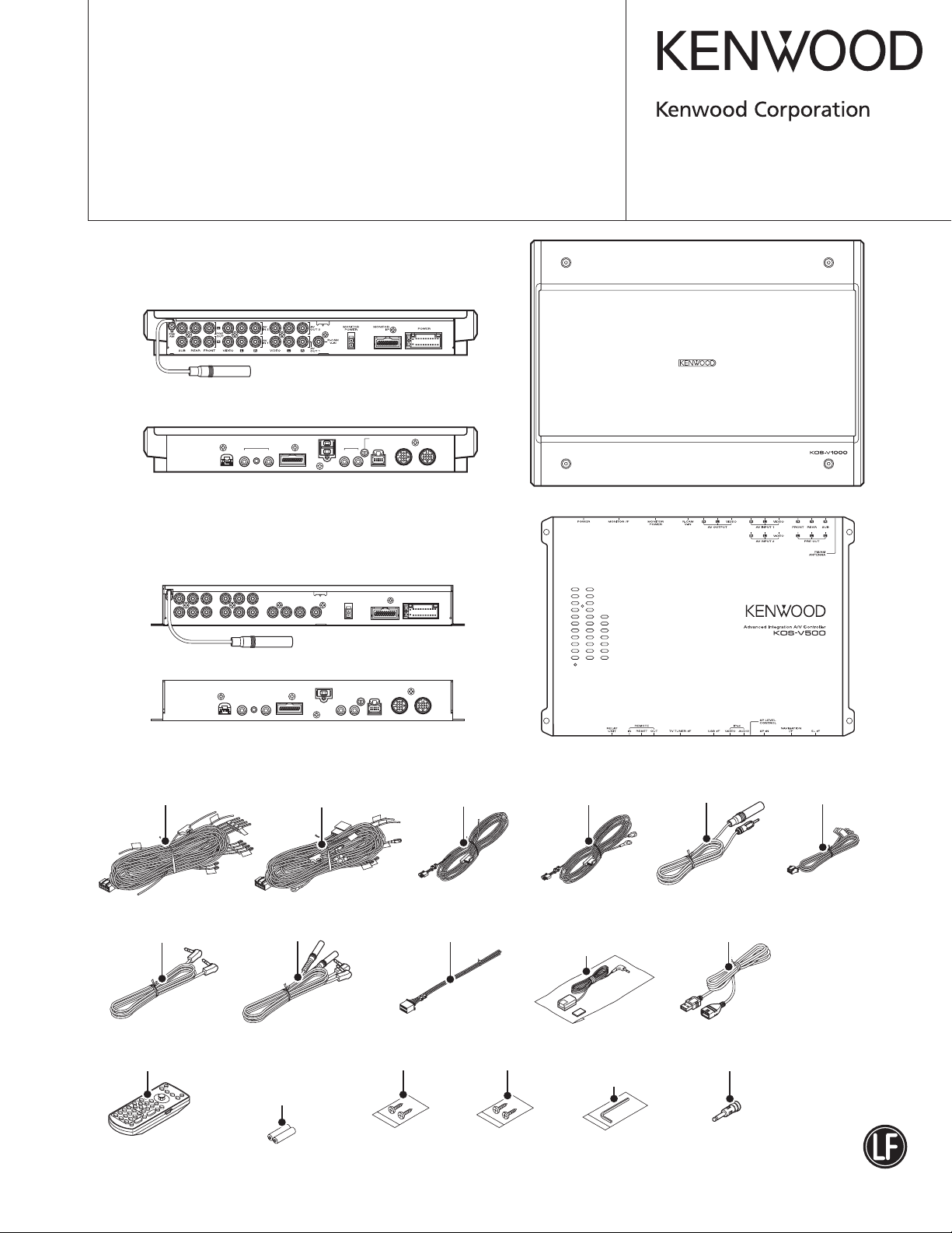
ADVANCED INTEGRATION A/V CONTROLLER
KOS-V1000/V500
SERVICE MANUAL
KOS-V1000
REAR
FRONT
SP LEVEL
CONTROL
RELAY
UNIT
REMOTE
IN OUT
RESET
TV TUNER
USB
I/F
I/F
VIDEO AUDIO
NAVIGATION
iPod
SP IN
5L I/F
I/F
© 2007-4 PRINTED IN JA PA N
B53-0527-00 (N) 521
Advanced Integration A/V Controller
KOS-V500
REAR
FRONT
DC cord(K,M type)
(E30-6682-05)
(6m)
Cord with plug
(E30-6697-05)
(6m)
DC cord(E type)
(E30-6683-05)
(6m)
Cord with plug
(E30-6698-05)
(3.5m)
DC cord(K,M type)
(E30-6700-05)
(GND1.5m,BU6m) (GND1.5m,BU6m)
Connecting cord assy
(E30-6145-05)
DC cord(E type)
(E30-6699-05)
Remote control
sensor assy
(T95-0273-05)
(190mm)
(6m)
Cord with plug
(E30-6483-05)
(6m)
Cord with plug
(E30-6696-05)
Cord with plug
(E30-6694-05)
(1m)
(3.5m)
x2 (KOS-V1000)
Remote controller assy
(A70-2082-15)
RC-DV330
Size AAA battery
(Not supplied)
Screw set
(N99-1782-05)
Screw set
(N99-1782-05)
Accessories
(KOS-V1000)
(W01-1699-05)
This product complies with the
Antenna adaptor(E type)
(T90-0552-05)
This product uses Lead Free solder.
RoHS directive for the European market.
KOS-V1000/V500
The IC106 in the DIGITAL I/O UNIT (X88-2020-10/13) is not a replaceable component.
●
In case of defective of this IC, replace the entire unit (X88-2020-10/13).
TEST MODE are the same as KVT-719DVD. Please refer to the service manual (KVT-719DVD: B53-0507-00).
●
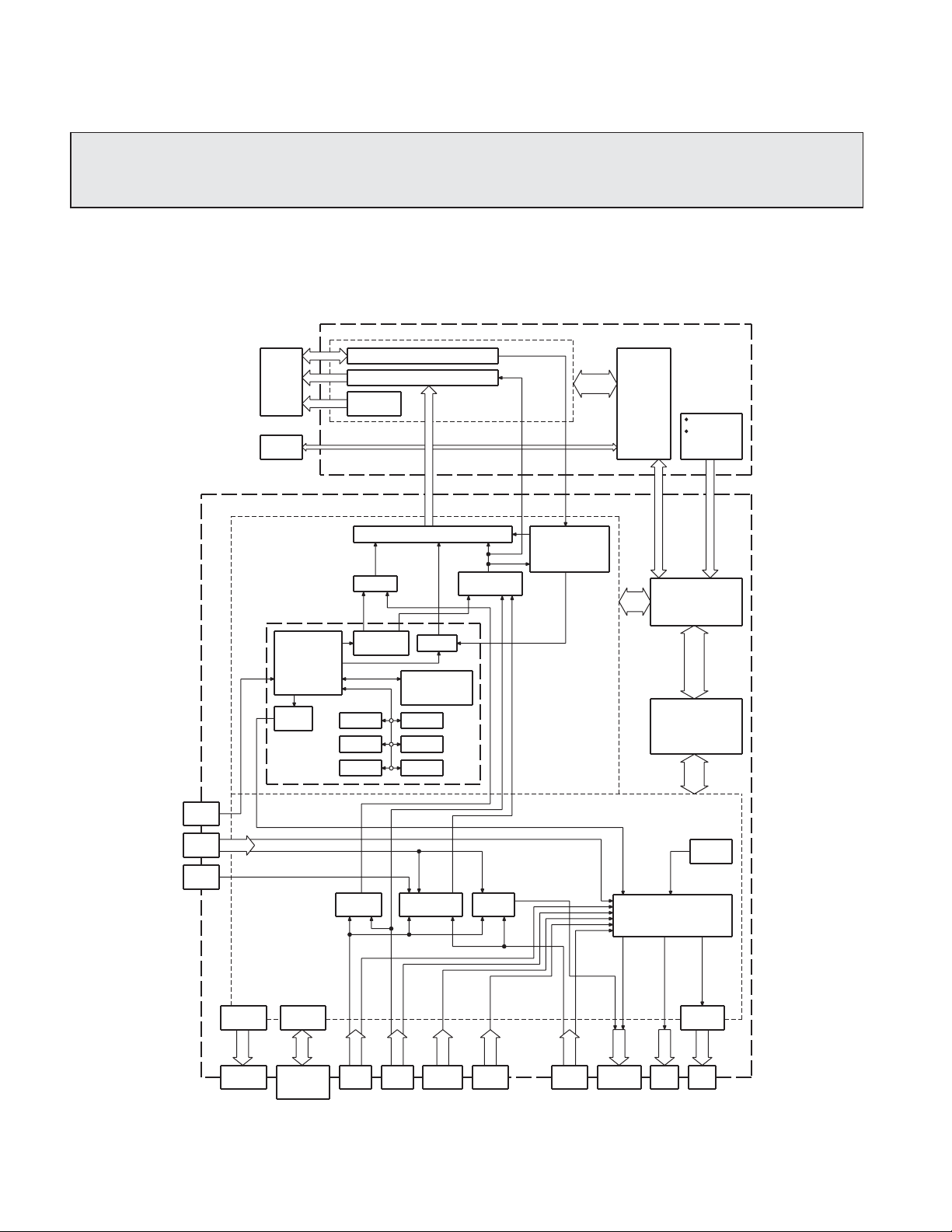
BLOCK DIAGRAM
SYSTEM
TIMING CONTROLLER
LCD
TOUCH
PA NE L
CHROMA GAMMA DECODER
INVERTER
CIRCUIT
MONITOR
u-COM
(X35)
KEY
REMOTE
CONTROL
RECEIVER
USB
iPod
REAR
CAM
(X14)
MEDIA
PROCESSOR
AUDI O
DAC
(X88)
CHROMA DECODER IC
RGB SW
VIDEO
ENCODER
SDRAM
FROM
RGB SW
COMPOSITE
SW
OSD
iPod
ATTESTATION
IC
SRAM
FROMSDRAM
FROM
COMPOSITESWAV OUT
SW
SYNCRONOUS
SEPARATER
& TIMING SHIFT
CIRCUIT
SYSCON
AUDI O
u-COM
AM/FM
TUNER
AUDIO INPUT SELECTOR
& E-VOLUME
RELAY
CIRCUIT
RELAY
OUT
I/F
CIRCUIT
REMOTE
CONTROL
I/F
NAVI
I/F IF
LX-BUS SP-IN
IF
TV
I/F
AV-I NIFAV-OUTIFPRE
POWER
AMP
SP
OUT OUT
2
POWER SUPPLY
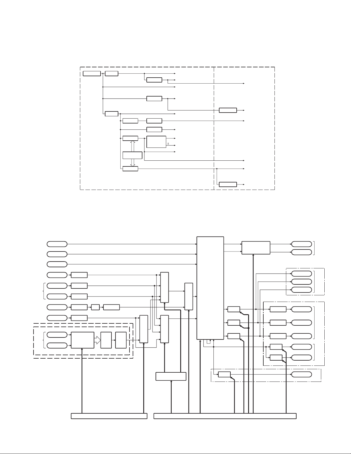
KOS-V1000/V500
BLOCK DIAGRAM
AUDIO
(X14-982) (X88-202)
IC1
BU:9.5~16V 5V REG.
Q7
SW 14V
5V
Q9
12V 5V
12V REG.
Q103 IC3
5V 12.5V
SW 5V
IC100
DC/DC
CONVERTER
Q102
3.3V
SW 3.3V
IC2
3.3V REG.
Q518
8V REG.
IC4
5V REG.
Q11
5V REG.
DC/DC
CONVERTER
SUB PROCESSOR
AUDIO MUTE CIRCUIT
3.3V
MAIN PROCESSOR
14.4V
POWER AMP
RELAY CONTROLLER
LX BUS
TV TUNER BOX
8V
E-VOL
ISOLATION AMP
AUDIO SELECTOR
TUNER
REFERENCE VOLTAGE CIRCUIT
REFERENCE VOLTAGE CIRCUIT
VIDEO SELECTOR
5V
VIDEO AMP
CHROMINANCE DECODER
SYNCRONOUS SEPARATER
CHROMINANCE DECODER
11V
SP-IN AMP
PRE OUT AMP
VIDEO LOGIC CIRCUIT
REMOTE CONTROL CIRCUIT
TV TUNER I/F
RDS DECODER
3.3V
8V
5V
5V
3.3V
IC332
5V REG.
IC105
1.8V REG.
SRAM
5V
AUDIO DAC
LPF
PLL
VIDEO DAC
VIDEO AMP
USB VBUS
PLL
VIDEO DAC
MAIN CPU
FLASH ROM
SDRAM
CO-PROCESSOR for iPod
OSD
CPLD
1.8V
MAIN CPU
A600 FM/AM
J804 NAVI-IF
J802 LX-IF
IC801
J803 TV-IF ISO AMP
IC707
AV IN-1 ISO AMP
J700
AV IN-2
IC706
ISO AMP
IC803
J805 SP IN ISO AMP
IC401
J400 iPod ISO AMP
IC106
USB-1
J101
USB-2
MEDIA
PROCESSOR
X88-202
X14-982
IC805
VR BUFFER
IC301
DAC
IC305
L.P.F.
IC400
AOUT SW5/6
SELECTOR
IC605
SELECTOR
IC604
SELECTOR
Q8,9
Q10,11
IC603
SERIAL/PARALLEL
CONVERTOR
IC602
SELECTOR
AIN SEL5/6
IC600
TUNER PA0
AUX
CH
E-VOL
CD (MAIN)
MD (SUB)
MUXB
MUXC
ACIN3
VOL.IN
IC601
FL/FR
4ch POWER AMP
RL/RR
PA1
FL/FR
RL/RR
USED ONLY
KOS-V500
FL/FR
RL/RR
PW IC MUTE
USED ONLY
KOS-V1000
IC954
LD0
MUTE BUFFER
FL/FR
IC952
LD1
MUTE BUFFER
RL/RR
IC953
LD2
MUTE BUFFER
USED ONLY
KOS-V500
MUTE
MUTE
AVOUT1
AVOUT2
MUTE AVOUT
J500
J600
SUB
J600
SUB
J951
J951
SREQ, MREQ
RST, TX, RX,
INI, STB, CON,
IC300
SYSTEM MICROCOMPUTER
AUD MUTEB/C
AUD MUTE0~2,
A SDA, A SCL,
IC902
AUDIO MICROCOMPUTER
AOUT MUTEB
PRE MUTESW
PRE MUTEF
AOUT MUTEB
3
4
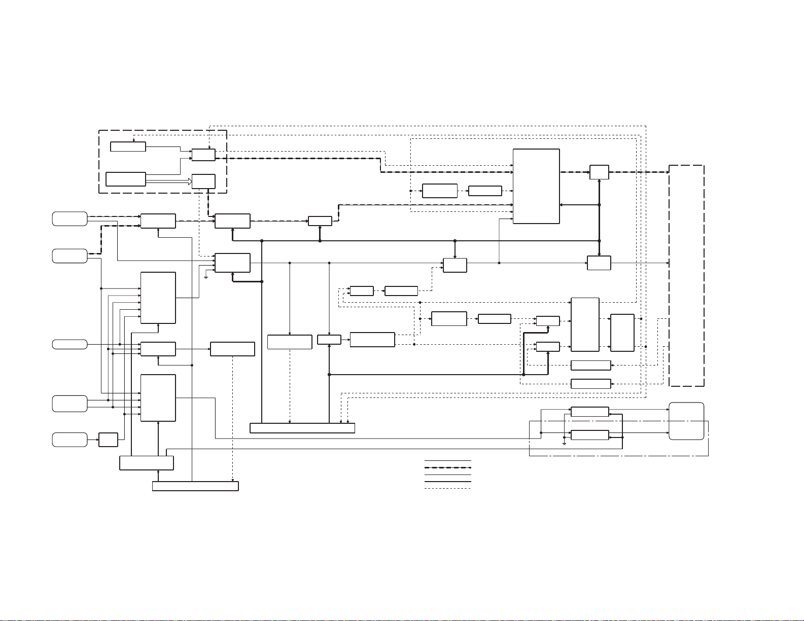
KOS-V1000/V500
VISUAL
J804
NAVI-IF
J803
TV-IF
J702
REAR-CAM
J700
AV IN-1
AV IN-2
J401
iPod
(X88-202)
IC300
IC106
MEDIA
PROCESSOR
IC402
ISO
AMP
IC603
DOT CLK
PLL
OS CLK
OS , DATA O
S CE
R[5:0], G[5:0], B[5:0]
IC700
RGB
SELECTOR
RGB SW
IC703
COMP
SELECTOR
TV
AV1
AV2
RC
iPod
SELECTOR
AUTO SW1/2
IC704
COMP
SELECTOR
TV
AV1
AV2
iPod
VINSEL1-3
SERIAL/PARALLEL
CONVERTER
VOUTSEL1-4
IC902
IC309
OSD
IC302
VIDEO
DAC
MAIN RGBCSYNC
IC213
RGB
SELECTOR
IC212
CSYNC
SELECTOR
MUTE
IC702IC701
SYNCRONOUS
SEPARATOR
AUDIO MICROCOMPUTER
V
H
OSD SYNC
OSD(RGB)
RGB VISUAL LINE
RGB SW3 RGB MUTE
VIN SW4/5
IC218
SYNCRONOUS
SEPARATOR
VSYNC DET
IC300
SYSTEM MICROCOMPUTER
IC214
MUTE
CONPOSITE VISUAL LINE
MUTE
SYNC DET
COMP MUTE
IC216
EX-OR INVERTER
IC204
SYNCRONOUS
SEPARATOR
IC217
H
V
IC209
MULTI
VIBRATOR
IC219
MULTI
VIBRATOR
IC211
CHROMINANCE
DECODER
SW2
RGB2
IC210
INVERTER
SYNC SEL VMUTE
IC215
CSYNC
SEL
IC220
INVERTER
KOS-V1000 ONLY
COMPOSITE VIDEO LINE
RGB VIDEO LINE
CONTROL LINE (SYSTEM MPU)
CONTROL LINE (AUDIO MPU)
SYNC SIGNAL LINE
OEM SW
HSY
RGB1
SYNC IN2
COMP
IC203
MUX
IC202
MUX
MUTE
MUTE
CS , DATA ,
CLK,
VIN SW2,
SYNC SW
IC205
IC200
IC201
IC705
IC951
IC206
RGB
AMP
MUTE
RGB OUT
IC208
VIDEO
AMP
BUFFER
LEVEL SHIFT
LEVEL SHIFT
VIDEO AMP
VIDEO AMP
VOUTSEL4
IC451
LEVEL
SHIFT
KOS-L702
RGB
BLOCK DIAGRAM
CSYNC
V
H
J951
AV OUT-1
AV OUT-1

KOS-V1000/V500
COMPONENTS DESCRIPTION
VIDEO CONTROL UNIT (X14-982x-xx)
●
Ref No. Function Description
IC1 Power Management Reference Voltage Regulator (BU5V)
IC2 Power Management Three terminal Regulater (BU3.3V)
IC3 Power Management
IC4 Volutage Regulator with Shut Down Switch (Adjustable Voltage) (M_V5V)
IC5,6 Power Management Three terminal Adjustable Regulater (V-5V,A8V etc)
IC100 Power Management
IC200,201 2-INPUT OR GATE level shift 3.3V → 5.0V
IC202,203
IC204 Video Signal
IC205 TRIPLE NON-INVERTER 3 Buffer
IC206 Video Driver 3channel 75Ω driver with 6dB amplifi er
IC208 Video SW 2-Input 1-Output 1-Circuit Video Switch Clamp, 6dB AMP, 75Ω Driver
IC209 MONOSTABLE MULTIVIBRATOR
IC210 INVERTER Buffer
IC211 Video interface
IC212 Video SW 5in, 3CTL,1out
IC213,214 Video SW 2-Input 1-Output 3-Circuit Video Switch
IC215 Video SW 2-Input 1-Output 1-Circuit Video Switch Clamp
IC216 EXCLUSIVE OR GATE
IC217 2-INPUT NOR GATE
IC218 Video Signal No-adjustment Sync Separator
IC219 MONOSTABLE MULTIVIBRATOR
IC220 2-INPUT NOR GATE
IC300 Voltage Detectors (RESET IC) Power monitor for microcomputers and reset for CPUs (for system microcomputer)
IC301 EEPROM 8bit EEPROM for system µ-com
IC302 EEPROM ROM CORRECTION
IC303 Microcomputer System Microcomputer
IC304 2-INPUT OR GATE level shift 3.3V → 5.0V
IC305 TRIPLE NON-INVERTER 3 Buffer
IC400 Differential 4ch Multiplexer iPod out audio: select from USB_LR or iPod_LR
IC401 ISOLATION AMP Ground Noise Isolation Amplifi er (for iPod Audio out)
IC402 ISOLATION AMP Single isolation amplifi er developed by the video signal (for iPod Video out)
IC451 TRIPLE NON-INVERTER 3 Buffer
IC600 Gain contol (E-VOL) 6-channel multimedia approach
IC601 Audio Power Amplifi er 4×50W/4Ω Power Amplifi er (for KOS-500)
IC602 Differential 4ch Multiplexer MAIN2 out audio: select from MAIN1 or SP-IN
2-CHANNEL MULTIPLEXER/
DEMULTIPLEXER
Three Outputs DC/DC Converter from a 3.3V or 5V Supply for designed use in TFT-LCD
panels (+11V,-11V,12.5V)
Dual 5V/3.3V Step-Down DC/DC Converter 550kHz, 2Phase Synchronous Regulaters
(SW3.3V, SW5V)
Synchronous Signal Separator and Detector, performs Horizontal and Vertical
synchronous signal from composit video signals, suitable for car navigation and LCD TV.
Video interface IC for a TFT-LCD, Automatic identifi cation of color system, Video/chroma
signal processor, Two RGB input lines (one for OSD)
5

KOS-V1000/V500
COMPONENTS DESCRIPTION
Ref No. Function Description
IC603 Sirial/Parallel convertor 12bit Serial IN Parallel OUT Driver
IC604,605 Differential 4ch Multiplexer
IC606 Tuner RDS Demodulator
IC700 Video SW 2-Input 1-Output 3-Circuit Video Switch
IC701 Video SW 3in, 2CTL, 1out
IC702 Video Signal No-adjustment Sync Separator
IC703,704 Video SW 5in, 3CTL, 1out
IC705 Video SW 2-Input 1-Output 1-Circuit Video Switch Clamp, 6dB AMP, 75Ω Driver
IC706,707 ISOLATION AMP Ground Noise Isolation Amplifi er (for iPod Audio out)
IC800 2-INPUT AND GATE pass remote control code “active=L”
IC801 ISOLATION AMP Ground Noise Isolation Amplifi er (for iPod Audio out)
IC802 2-INPUT AND GATE remote control for NAVI
IC803 OP AMP Dual operational amplifi er (SP IN)
IC804 OP AMP Dual low noise operational amplifi er(SP IN) (for KOS-500)
IC805 OP AMP Dual operational amplifi er (SP IN)
IC806 2-INPUT AND GATE pass remote control code “active=L”
IC807 2-INPUT OR GATE level shift 3.3V → 5.0V
IC900 EEPROM ROM CORRECTION
IC901 QUAD 2-INPUT AND GATE logic cirsuit for start up audio microcomputer
IC902 Microcomputer Audio Microcomputer
IC903 Voltage Detectors (RESET IC) Power monitor for microcomputers and reset for CPUs (for audio microcomputer)
IC951 Video SW 2-Input 1-Output 1-Circuit Video Switch Clamp, 6dB AMP, 75Ω Driver
IC952~954 OP AMP Dual operational amplifi er (PRE_OUT)
IC955 OP AMP Dual low noise operational amplifi er (1/2 Vcc for KOS-1000)
IC956 OP AMP Single-Supply Operational Amplifi er
IC957
Q1 Detection Switch Transisitor for surgeptotector
Q2 Detection Switch Transisitor for BU_DET detection
Q3 Detection Switch Transisitor for ACC_DET detection
Q4 Control Switch Transisitor for P_ON control circuit, SW14V
Q5,6 Control Switch Transisitor for SW14V REG circuit
Q7 Power Switch P Channel Power MOSFET. Low drain-source ON resistance (SW14V)
Q9 POWER TR Transisitor for 12V REG circuit
Q10 Detection Switch Transisitor for 12V REG circuit
Q11 POWER TR For Power Amplifi cation (V-5V)
Q12 Detection Switch Transisitor for SP active detection
Q21 Control Switch Transisitor for PON control circuit, A8V
Q22 Control Switch Transisitor for PON control circuit, A8V
Q101 Control Switch Transisitor for POWER_START control of DC/DC CONV
DUAL BUS BUFFER NON
INVERTED, 3-STATE OUTPUTS
SUB out audio: select from TV, AVIN2, iPod or AVIN1
MAIN1 out audio: select from TV, AVIN2, iPodUSB, or AVIN1
logic cirsuit for remote control
6

KOS-V1000/V500
COMPONENTS DESCRIPTION
Ref No. Function Description
Q102,103 High Speed Power Switch Power MOS FET with Schottky Barrier Diode (SW3.3V, SW5V)
Q104 Control Switch Transisitor for POWER_START control of DC/DC CONV
Q200 Control Switch Transisitor for NTSC/PAL select cntrol
Q201 Control Switch Transisitor for NTSC/PAL select cntrol
Q203 Control Switch Transisitor for OEM_SW
Q205 Driver Transisitor for SYNC drive
Q208 Control Switch Transisitor for level shift control of EP-SYNC
Q209 Control Switch Transisitor for SYNC drive
Q210 Driver Transisitor for COMP_MUTE control
Q211 Driver Transisitor for level shift control of SYNC
Q300 Detection Switch Transisitor for RESET detection circuit
Q301 Detection Switch Transisitor for RESET detection circuit
Q400,401 Control Switch Transisitor for USB/iPod select cntrol
Q500 Detection Switch Transisitor for REVERSE detection circuit
Q501 Detection Switch Transisitor for Park_DET detection circuit
Q502 Detection Switch Transisitor for ILLUMI_DET detection circuit
Q503 Detection Switch Transisitor for BU_DET detection circuit
Q506 Medium Power TR Transisitor for P_CON control circuit
Q507 Control Switch Transisitor for P_CON control circuit
Q508 Control Switch Transisitor for P_CON control circuit
Q509 Control Switch Transisitor for P_CON control circuit
Q510 Medium Power TR Transisitor for ANT_CON control circuit
Q511 Control Switch Transisitor for ANT_CON control circuit
Q512 Control Switch Transisitor for EXT_AMP control circuit
Q518 POWER TR For Power Amplifi cation(A8V)
Q522 Control Switch Transisitor for stop control when over current is detected, RELAY1 circuit
Q523 Control Switch Transisitor for RELAY1 control circuit
Q524 POWER TR Transisitor for RELAY detection & control circuit
Q525 Control Switch Transisitor for over current detection of RELAY1 control circuit
Q526 Detection Switch Transisitor for RELAY_DET1 detection circuit
Q527 Control Switch Transisitor for RELAY1 control circuit
Q529 Control Switch Transisitor for RELAY2 control circuit
Q530 POWER TR Transisitor for RELAY detection & control circuit
Q531 Control Switch Transisitor for over current detection of RELAY2 control circuit
Q532 Detection Switch Transisitor for RELAY_DET2 detection circuit
Q533 Control Switch Transisitor for RELAY2 control circuit
Q600,601 Control Switch Transisitor for selsct MAIN2 out audio
Q602 Mute Switch Transisitor for FRONTL of PREOUT_MUTE circuit
Q603 Muting Driver Transisitor for PRE_OUT_MUTE control circuit, FRONTL /R & REARL/R (Q603)
Q604 Mute Switch Transisitor for FRONTR of PREOUT_MUTE circuit
Q605 Mute Switch Transisitor for REARL of PREOUT_MUTE circuit
7

KOS-V1000/V500
COMPONENTS DESCRIPTION
Ref No. Function Description
Q606 Mute Switch Transisitor for REARR of PREOUT_MUTE circuit
Q607 Mute Switch Transisitor for SWL of PREOUT_MUTE circuit
Q608 Mute Driver Transisitor for PREOUT_MUTE control circuit, SWL/R
Q609 Mute Switch Transisitor for SWR of PREOUT_MUTE circuit
Q610 Control Switch Transisitor for Tunner Power control circuit, AM+B
Q611 POWER TR For General Purpose Amplifi cation (AM+B)
Q700 Mute Switch Transisitor for AVOUT(R or 1R) of PREOUT_MUTE circuit
Q701 Mute Driver Transisitor for AVOUT_MUTE control circuit, AVOUTL/R or AVOUT1L/1R & AVOUT2L/2R
Q702 Mute Switch Transisitor for AVOUT (L or 1L) of PREOUT_MUTE circuit
Q703 Control Switch Transisitor for mute control of 1/2 Vcc circuit when is off
Q704,705 Control Switch Transisitor for RIP_MUTE control circuit
Q900 Control Switch Transisitor for MUTE control when A_RESET is active
Q901,902 Detection Switch Transisitor for RESET detection circuit
Q903 Control Switch Transisitor for A_RESET control
Q904 Detection Switch Transisitor for RESET detection circuit
Q906 Control Switch Transisitor for MUTE control when BU_DET SUB is detected
Q951 Control Switch Transisitor for stop control when over current is detected, RELAY3 circuit
Q952 Control Switch Transisitor for RELAY3 control circuit
Q953 POWER TR Transisitor for RELAY detection & control circuit
Q954 Control Switch Transisitor for over current detection of RELAY3 control circuit
Q955 Detection Switch Transisitor for RELAY_DET3 detection circuit
Q956 Control Switch Transisitor for RELAY3 control circuit
Q957 Control Switch Transisitor for stop control when over current is detected, RELAY4 circuit
Q958 Control Switch Transisitor for RELAY4 control circuit
Q959 POWER TR Transisitor for RELAY detection & control circuit
Q960 Control Switch Transisitor for over current detection of RELAY4 control circuit
Q961 Detection Switch Transisitor for RELAY_DET4 detection circuit
Q962 Control Switch Transisitor for RELAY4 control circuit
Q963 Mute Switch Transisitor for AVOUT2R of PREOUT_MUTE circuit
Q964 Mute Switch Transisitor for AVOUT2L of PREOUT_MUTE circuit
8

KOS-V1000/V500
MICROCOMPUTER’S TERMINAL DESCRIPTION
System µ-com: 703261YGC315A (X14-982: IC303)
●
Pin No. Pin Name Application I/O Note
1 AVREF0 Power supply terminal -
2 AVSS GND -
3 V_MUTE Mute signal of composite video signal for monitor O
4 NC (Not used) O
5 AVREF Reference voltage input -
6 NC (Not used) O
7 CIR_BU_DET Backup detection signal for X88 O
8 FLMD0 (Used only for software update) I
9 VDD Power supply terminal -
10 REGC Capacitor connection terminal for reducing power supply noise -
11 VSS GND -
12 X1 Inverter input terminal for system clock [4.953MHz] -
13 X2 Inverter output terminal for system clock [4.953MHz] -
14 RESET System reset input I
15 XT1 Inverter input terminal for sub clock [32.768kHz] -
16 XT2 Inverter output terminal for sub clock [32.768kHz] -
17 PANEL_DET Monitor connection detection I
18 VSY (VD) V-SYNC input I
19 BU_DET Backup detection I
20 OSD_MODE OSD circuit switching control signal O
21 ACC_DET ACC detection I
22
23
24
25 CIR_TX DATA signal to media processor O
26 CIR_RX DATA signal from media processor I
27 CIR_INI Initialization signal for media processor O
28 CIR_RESET Reset signal for media processor O
29 CIR_STB Standby signal for media processor I
30 CIR_MREQ Request signal to media processor O
31 CIR_SREQ Request signal from media processor I
32 CIR_CON Media processor operation permission O
33 EVSS GND -
34 EVDD Power supply terminal -
35 SDA DATA I/O signal with E2PROM I/O
36 SCL CLOCK signal to E2PROM O
37 NC (Not used) O
38 PLL_EN PLL IC enable signal O
39 PGOOD Error detection in power supply voltage to DC/DC converter IC I
40 SYNC_DET Detection of composite video signal in monitor output I
_CS CS signal to Chroma γ -IC O
γ
_DATA DATA signal to Chroma γ -IC O
γ
_CLK CLOCK signal to Chroma γ -IC O
γ
9

KOS-V1000/V500
MICROCOMPUTER’S TERMINAL DESCRIPTION
Pin No. Pin Name Application I/O Note
41 NC (Not used) O
42 MON_SYS_ON Power ON/OFF control for monitor µ-com O
43 MON_S_DATA DATA signal to monitor µ-com O
44 MON_M_DATA Communication with monitor µ-com I
45 MON_RESET Monitor µ-com reset O
46 POWER_START DC/DC converter IC ON/OFF control O
47 POWER_PWM
48 PON Main power supply ON/OFF control O
49 REMO_PWM Remote control code conversion signal of touch panel signal O
50 HSY (HD) H-SYNC input I
51 PLL_MDATA Control DATA signal to PLL IC O
52 PLL_CLK Control CLOCK signal to PLL IC O
53 SYS_SDATA DATA signal from AUDIO µ-com I
54 SYS_MDATA DATA signal to AUDIO µ-com O
55 SYS_CLK Communication CLOCK signal with AUDIO µ-com O
56 SYS_SREQ Request signal from AUDIO µ-com I
57 TYPE3 Model detection terminal O 500: Fixed to Lo, 1000: Fixed to High
58 MON_POWER Monitor power KEY ON/OFF input I
59 SYS_MREQ Request signal to AUDIO µ-com O
60 SYS_ON AUDIO µ-com ON/OFF control O
61 NC (Not used) O
62 TYPE1 Model detection terminal I Not monitored in KOS
63 TYPE2 Model detection terminal I KOS is fi xed to High
64 NTSC_PAL NTSC/PAL determination input I
65~67 NC (Not used) O
68 REMO_POWSW
69 BVSS GND -
70 BVDD Power supply terminal -
71 WRT_E2P Used when writing E2PROM I
72 RGBOUT_MUTE RGB output mute signal to monitor O
73,74 NC (Not used) O
75 SYNC_SEL Composite switching signal to monitor output O
76 FLMD1 (Used only for software update) I
77 REMO_SEL Remote control output switching signal O
78 OEM_SW SYNC signal switching control O
79 VIN_SW2 COMP/RGB input switching for Chroma γ IC O
80 SYNC_SW2 SYNC input switching for Chroma γ IC O
81 RGB_SW3 RGB video signal selector control O
82 VIN_SW4 RGB video signal selector control O
Reference CLOCK for external synchronization of DC/DC
converter IC
System ON/OFF control input from external remote control
ASSY (not used)
O
I
10
KOS-V1000/V500
MICROCOMPUTER’S TERMINAL DESCRIPTION
Pin No. Pin Name Application I/O Note
83 VIN_SW5 Composite video signal switching control O
84 COMP_MUTE
85 RGB_MUTE Mute control of input unit in Chroma γ IC for RGB video signal O
86 AOUT_SW5 Audio signal selector control O
87 AOUT_SW6 Audio signal selector control O
88,89 NC (Not used) O
90 VR For PHASE/TINT automatic adjustment I
91 VG For RGB level automatic adjustment I
92 VB For PHASE/TINT automatic adjustment I
93 NC (Not used) O
94 NT_PAL NTSC/PAL switching signal for monitor O
95~99 NC (Not used) O
100 TYPE0 Destination (Voltage reading) I
Mute control of input unit in sync separation IC for composite
video signal
O
Setup of destination
MODEL Category Destination TYPE3 TYPE2 TYPE1 TYPE0
K010 *
KOS-V
TYPE0 Setup voltage
Destination
K 0.00 0.00 0.41
E 0.42 0.83 1.23
M 1.24 1.65 2.06
500
1000
µ-com setup value
min Mid point voltage max
E010 *
M0 1 0 *
K110 *
E110 *
M1 1 0 *
11
KOS-V1000/V500
MICROCOMPUTER’S TERMINAL DESCRIPTION
SW Logic
To MONITOR(OP_MONITOR or OEM_MONITOR)
●
_VIN
Name of control line
Terminal number 79 80 81 82 83 84 85 78
Full_GRAPHIC 1 0 0 0 0 0 0 1
iPod_VIDEO 0 0 0 1 0 0 1 1
AVIN/VIN 0 0 0 1 0 0 1 1
OP_
MONITOR
OEM_
MONITOR
* 1: Superimpose OSD without switching the image shown on the display (monitor output).
The specifi cations for these yellow cells are not used this time and the no-input control method as described in the followings is used.
TV (Other than SECAM) 0 0 0 1 0 0 1 1
TV (SECAM) 1 0 1 1 0 0 0 1
NAVI 10101001
PARK_OFF * 1 * 1 * 1 * 1 * 1 * 1 * 1 * 1
REVERS_OFF 0 0 0 1 0 0 1 1
NAVI_OFF 1 0 1 0 1 0 0 1
Full_GRAPHIC 1 1 0 0 0 0 0 0
iPod_VIDEO 0 0 0 1 0 0 1 0
AVIN/VIN 0 0 0 1 0 0 1 0
TV (Other than SECAM) 0 0 0 1 0 0 1 0
TV (SECAM) 1 0 1 1 0 0 0 0
NAVI 10101000
PARK_OFF * 1 * 1 * 1 * 1 * 1 * 1 * 1 * 1
REVERS_OFF 0 0 0 1 0 0 1 0
NAVI_OFF 1 0 1 0 1 0 0 0
γ
_SW2
_SYNC
γ
_SW2
RGB_SW3 VIN_SW4 VIN_SW5
COMP
_MUTE
RGB
_MUTE
OEM_SW
RGB_OUT control
●
“RGB_OUT” operation is controlled with the OR of “V_MUT” and
specifi cations shown in the next table.
Name of control line
Terminal number 72
Full_GRAPHIC 0 1
iPod_VIDEO 0 1
AVIN/VIN 0 1
OP_
MONITOR
(In house)
OEM_
MONITOR
(Out-ofhouse)
* 1: Superimpose OSD without switching the image shown on the
display (monitor output).
TV (Other than SECAM) 0 1
TV (SECAM) 0 1
NAVI 0 1
PARK_OFF * 1 1
REVERS_OFF 0 1
NAVI_OFF 0 1
Full_GRAPHIC 0 1
iPod_VIDEO 1 1
AVIN/VIN 1 1
TV (Other than SECAM) 1 1
TV (SECAM) 0 1
NAVI 0 1
PARK_OFF * 1 1
REVERS_OFF 1 1
NAVI_OFF 0 1
RGBOUT
_MUTE
V MUTE
Function
AUDIO switching SW (To MAIN, SUB, AV_OUT)
●
AOUT_SW5 AOUT_SW6
USB_AUDIO 0 1
iPod_AUDIO 1 0
Control method when there is no input
●
Decide if there is a signal or not based on the number of pulses that
is coming in the SYNC_DET terminal (pin40) within 100ms.
Name of
control line
µ-com terminal
number
Control IC - MM1503-E Control IC
terminal number
OP_
MONITOR
and
OEM_
MONITOR
* Plus “COMP_MUTE” to the control defi ned in the above table of
“To MONITOR (OP_MONITOR or OEM_MONITOR)”.
None 3 or less 1 1
Yes 4~7 0 0
None 8~44 1 1
Yes 45~79 0 0
None 80 or more 1 1
SYNC
_DET
SYNC_SW
40 76 84
-1-
COMP
_MUTE
12

KOS-V1000/V500
MICROCOMPUTER’S TERMINAL DESCRIPTION
Audio µ-com: 703030BYGCJ30 (X14-982: IC902)
●
Pin No. Pin Name Application I/O Note
1 TV_JUDGE TV-BOX new/old detection I
2 TUN_SCL F/E I2C clock output terminal O
3 NAVI_RX Navi control data input I
4 NAVI_TX Navi control data output O
5 TV_MC_REQ Communication request to TV_COM O
6 EVDD Power supply terminal -
7 EVSS GND terminal -
8 TV_SC_CON Start-up request to TV_COM O
9 BEEP BEEP O
10 MIX_REMO Remote control data input I
11 SYS_SREQ Communication request to SYS_COM O
12 SYS_MDATA SYS_COM communication data input I
13 SYS_SDATA SYS_COM communication data output O
14 SYS_MCLK SYS_COM communication clock I
15 SYS_MREQ SYS_COM communication request input I
16 EXT_CON EXT-CONT output O
17 VSYNC_DET Video detection I
18 VPP (Used only for software update) I
19 RGB_MUTE MUTE RGB except when NAVI or SECAM O
20 RGB_SW NAVI/SECAM switching O
21 AIN_SEL5 Audio-In switching O
22 AIN_SEL6 Audio-In switching O
23 R_QUAL RDS decoder QUAL input terminal I
24 R_DATA RDS decoder DATA input terminal I
25 R_AFS_H Switching constant when noise detected I/O
26 AM+B AM power ON O
27 AUTO_SW_1 SW for video detection O
28 AUTO_SW_2 Video detection, NTSC/PAL determination O
29 SEL_CLK CLK for Audio and Video selector O
30 SEL_DATA DATA for Audio and Video selector O
31 RESET System reset input I
32 XT1 (Not used) I
33 XT2 (Not used) O
34 REGC Capacitor connection terminal for reducing power supply noise -
35 X2 Inverter output terminal for system clock [19.800MHz] -
36 X1 Inverter input terminal for system clock [19.800MHz] -
37 VSS GND terminal -
38 VDD Power supply terminal -
39 CLKOUT (Not used) -
40 PRE_MUTESW PREout sub woofer MUTE O
13

KOS-V1000/V500
MICROCOMPUTER’S TERMINAL DESCRIPTION
Pin No. Pin Name Application I/O Note
41 PRE_MUTER PREout rear MUTE O
42 PRE_MUTEF PREout front MUTE O
43 RELAY_SW1 ON/OFF of external equipment relay control O
44 RELAY_SW2 ON/OFF of external equipment relay control O
45 RELAY_SW3 ON/OFF of external equipment relay control O Used only in KOS-V1000.
46 RELAY_SW4 ON/OFF of external equipment relay control O Used only in KOS-V1000.
47 RELAY_DET1 Detection of external equipment relay control I
48 RELAY_DET2 Detection of external equipment relay control I
49 RELAY_DET3 Detection of external equipment relay control I Used only in KOS-V1000.
50 RELAY_DET4 Detection of external equipment relay control I Used only in KOS-V1000.
51 ILL_DET ILL detection I
52 PAK_DET Parking detection I
53 REV_DET Reverse detection I
54 P_CON P-CON control output O
55 BVDD Power supply terminal -
56 BVSS GND terminal -
57 ANT_CON P-ANT control output O
58 NC (Not used) O
59 PWIC_STBY PWIC standby O
60 PWIC_MUTE PWIC_FR MUTE O
61 AUD_MUTEC E-VOL inputSEL_C MUTE O
62 AUD_MUTEB E-VOL inputSEL_B MUTE O
63 AUD_MUTEA E-VOL inputSEL_A MUTE O
64 AUD_MUTE2 E-VOL center, SWMUTE O
65 AUD_MUTE1 E-VOL rear MUTE O
66 AUD_MUTE0 E-VOL front MUTE O
67 AUD_SDA
68 AUD_SCL
69 PON A8V, V5V, SW5V ON/OFF O
70 LX_RST Hardware-reset to slave unit O
71 AVDD Power supply terminal -
72 AVSS GND terminal -
73 AVREF Reference voltage input -
74 PWIC_DCDET SP_FR output DC offset detection I
75 LINE_MUTE LINE-MUTE input detection I
76 NC (Not used) -
77 A_WRT_E2P Used when writing E2PROM I
78 LX_MUTE MUTE request from slave unit I
79 A_TYPE0 Destination (Voltage reading) I
E-VOL data output / ROM correction E2PROM communication
data input/output
E-VOL clock output / ROM correction E2PROM communication
clock output
I/O
O
14

KOS-V1000/V500
MICROCOMPUTER’S TERMINAL DESCRIPTION
Pin No. Pin Name Application I/O Note
80 A_TYPE1 Model detection terminal I Not monitored in KOS
81 A_TYPE2 Model detection terminal I KOS is fi xed to High
82 A_TYPE3 Model detection terminal I 500: Fixed to Lo, 1000: Fixed to High
83 TUN_IFC F/E IFC OUT input terminal I
84 TUN_SMET S meter input I
85 R_NOISE FM noise detection terminal I
86 RIP_MUTE Power IC inside O Used only in KOS-V1000.
87 BU_DET BU reduced voltage detection I
88 TV_SC_REQ Communication request from TV_COM I
89 SYS_ON SYS_COM communication control input I
90 R_CLK RDS decoder CLK input terminal I
91 LX_REQ_S Communication request from slave unit I
92 LX_REQ_M Communication request to slave unit O
93 LX_CON Start-up request to slave unit O
94
95
96
97 TV_SC_DATA DATA input from TV_COM I
98 TV_MC_DATA DATA output to TV_COM O
99 TV_BP_CLK CLK output to TV_COM O
100 TUN_SDA F/E I2C data input/output terminal I/O
LX_DATA_S/
A_FLASH_MDATA
LX_DATA_M/
A_FLASH_SDATA
LX_CLK/
A_FLASH_SCK
Data from slave unit / Data from Flash re-write terminal writer I
Data to slave unit / Data to Flash re-write terminal writer O
LX BUS clock / Clock from Flash re-write terminal writer O
15
KOS-V1000/V500
ADJUSTMENT
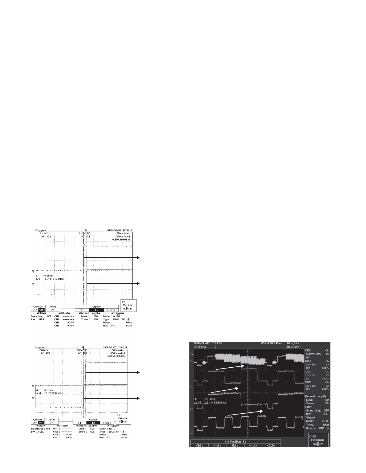
SYNC Timing adjustment
●
Use the arbitrary monitor. (When using the arbitrary monitor,
use the “Parking OFF” since the screen is shown dark when
the source is the composite source.)
• Conditions
Video source : NAVI source and VIDEO source
Input video : NAVI and VIDEO signals
Operation mode : Parking OFF (to display OSD)
1. Use the Parking OFF to check if there is any space
at the edge of OSD. When AV1 is entered in the
composite signal.
2. Change each source.
3. Check that there are no jitter noises on the OSD.
4. If the jitter noises are observed, fi ne-adjust by turning
VR201 (X14-982) to the position where the jitter noise
is removed while observing the screen.
5. After turning VR201, re-check the timing with VSEL.
Reference
Baseline when no input
Mono-multi
HSY
Monitor HSY
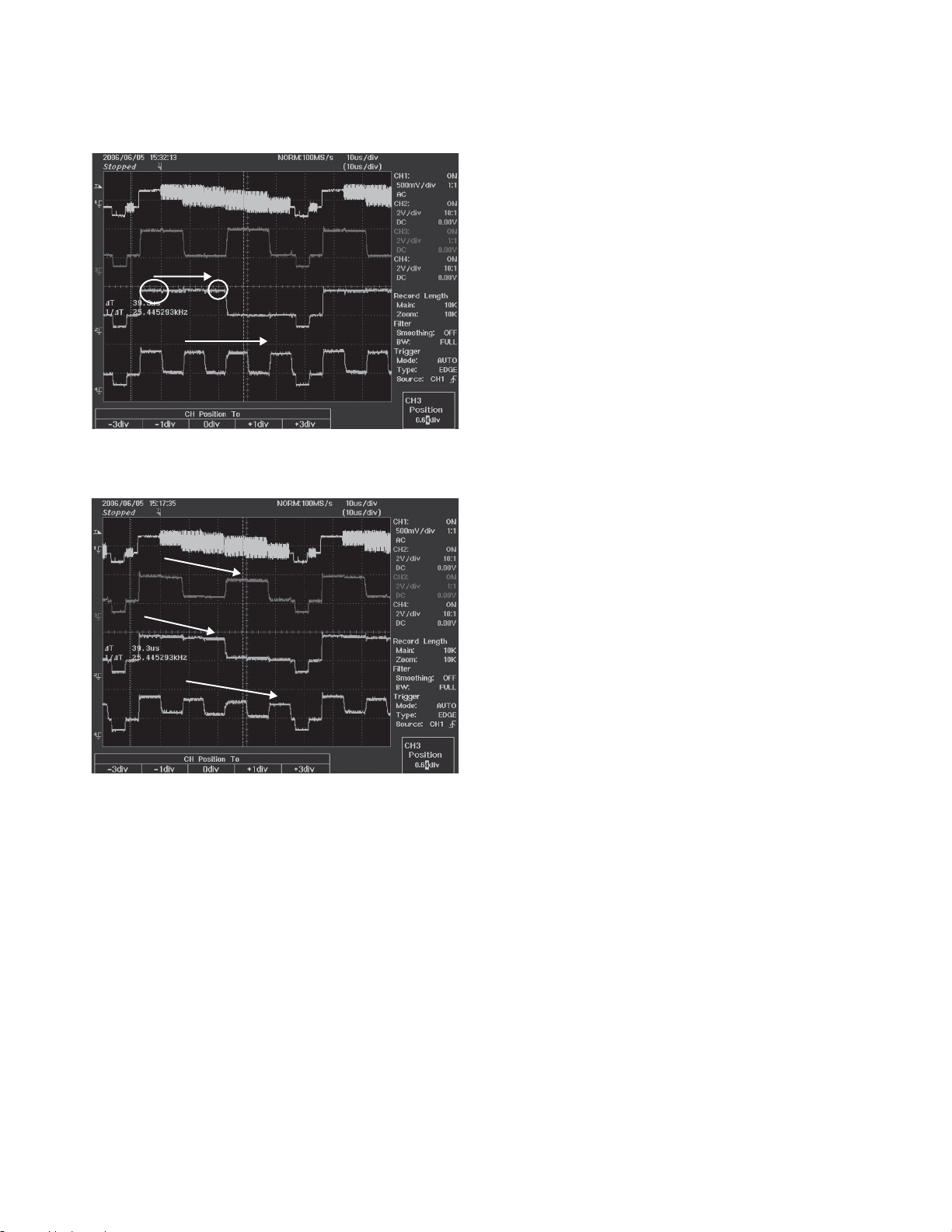
COLOR adjustment
●
• Conditions
Video source : NTSC composite video signal (AV-INI)
Input video : Color bar
Operation mode : Test Mode
• Adjustment
Adjust color with the remote controller by touching AUTO
Adjust, CHROMA FNC, and COLOR in this sequence
(AUTO Adjust → CHROMA FNC → COLOR) on the test
mode screen.
* To shift to the test mode, press the [Reset] key to start
the system while pressing the [MODE] and [VOL UP] keys
at the same time ([MODE] + [VOLUP]). Refer to KVT-
719DVD Service Manual (B53-0507-00) for the details of
the test mode.
1. Connect the adjustment connector pin. (Surface A)
Trigger with the composite or G signal and adjust color
as shown below while monitoring G signal.
The fi gure shown below is the output wave form of R, G,
and B colors.
2. Set the default values for COLOR register. (Default
value: 5C)
3. Shift to the COLOR adjustment screen and fi ne-adjust
the COLOR register.
Adjust the register by changing the COLOR value with
the UP/DOWN on the remote controller such that the
amplitude of one horizontal becomes constant.
Adjust the register so that the level of the K part is fl at.
4. After adjustment, press the fi nal [selection] key.
Color of OSD on the screen turns purple when the KEY
is pressed.
Then press the [end] key and when “Write OK” is
shown the adjustment is complete.
43K + 4.7K VR
OSD shifts to left when the above values are used. VR MAX 155ns
43K + 4.7K VR
OSD shifts to right when the above values are used. VR MIN 95ns
16
Mono-multi
HSY
Monitor HSY
COLOR : 70
When COLOR register is increased
KOS-V1000/V500
ADJUSTMENT
COLOR : 60
COLOR : 50
When COLOR register is set to 60
• Measurement equipment and etc.
Video signal generator
KOS-L702 monitor
Horizontal position default value for both of internal and
external monitors (Reference only)
Graphic 2
VIDEO (NTSC) 3
NAVI 2
VIDEO (PAL) 5
OSD default value
ALL 0
TINT/PHASE Automatic adjustment (PAL)
●
• Conditions
Video source : PAL composite video signal (AV-INI)
Input video : Magenta (Luster)
Operation mode : Test Mode
• Adjustment
Start the automatic adjustment by touching AUTO Adjust
and TINT/PHASE in this sequence (AUTO Adjust
TINT/PHASE) on the test mode screen.
→
When COLOR register is decreased
RGB Automatic adjustment
●
• Conditions
Video source : NTSC composite video signal (AV-INI)
Input video : White 100%
Operation mode : Test Mode
• Adjustment
Start the automatic adjustment by touching AUTO Adjust
and RGB in this sequence (AUTO Adjust → RGB) on the
test mode screen.
* Make this adjustment after setting up Chroma auto
CONT-VIDEO.
(* Make the adjustment after the TINT and PHASE
adjustments of NTSC.)
• Measurement equipment and etc.
Video signal generator
KOS-L702 monitor
17
A B C D E
3
9
2
3
4
8
3
D809
2
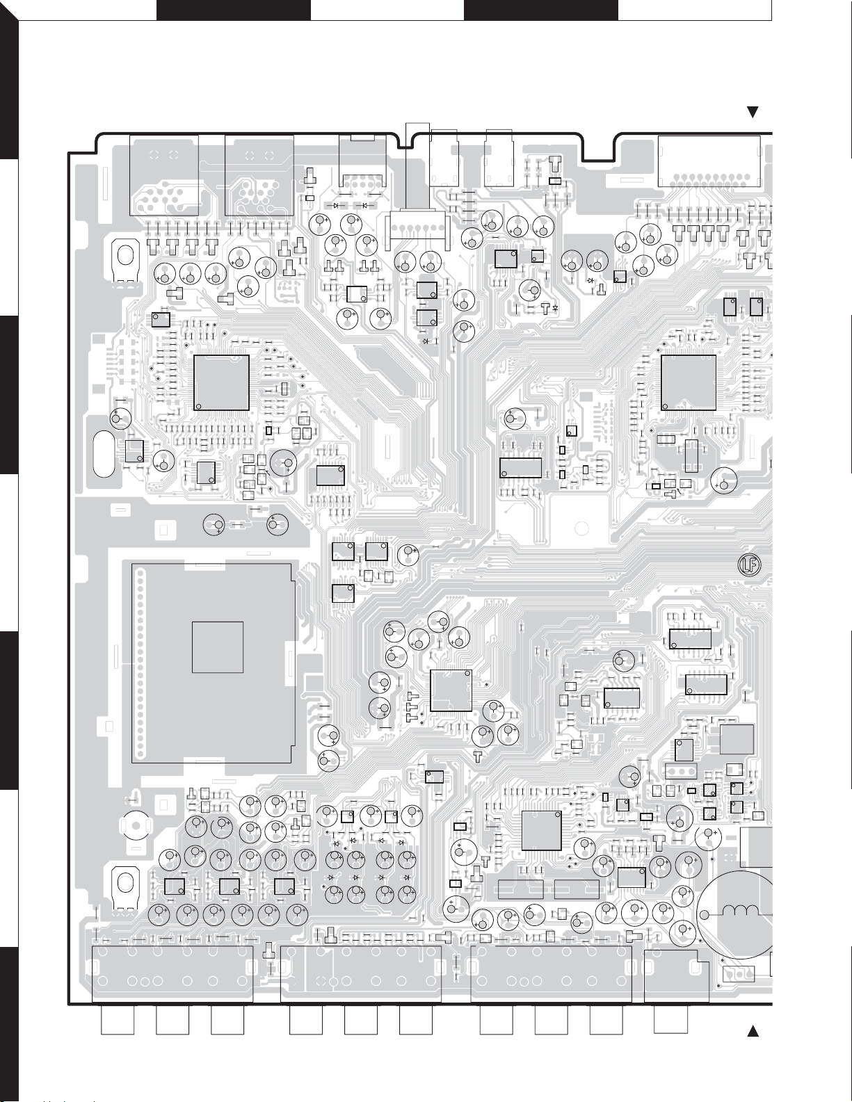
KOS-V1000/V500
1
PC BOARD (COMPONENT SIDE VIEW)
VIDEO CONTROL UNIT X14-982x-xx (J76-0395-11)
J803
19
20
R839
D814
R343
TP301
R382
X301
C273
R346
R345
R389
R312
R360
R388
R838
C304
R837
D815
R314
R358
R835
R836
D812
D816
IC301 IC302
481
5
R385
R392
R337
R335
R330
R329
R328
R327
R326
R325
R304
R302
26
R318
R315
R317
R316
C276
R357
L211
9
R840
R841
R842
C806
D813
C803
R341
R342
R421
R420
75 51
IC303
125
R321
X300
C303
C323
Q300
BE
BE
Q301
D301
C274
C277
R364
16 9
IC213
C275
18
C272
16
IC214
8
1
C212
C205
C206
C219
C209
IC204
13
IC220
C223
C226
13
54
TP222
14
87
C194
5
8
C193
IC219
IC202
C191C192
R219
TP220
C220
TP221
R220
R199
R238
1458
4
1
C215
TP223
VR201
IC205
IC203
4
R217
R218
CN202
X200
R216
1
CN203
Q201
C216
C225
C222
C227
R750
J702
R215
R214
L213
D212
R301
C284
C213
2
R833
R823
C306
C324
L201
1
R
R831
R834
R832
R830
D810
R824
D811
481
C305
5
R386
R394
R336
R334
R31
R31
R32
R32
R30
R32
L300
R307
R306
TP245
TP226
5814
851
R221
Q
BE
D13
13
R872
IC802
R634
8
9
R629
Q605
D704
R722
L602
L601
R990
C836
D831
R886
R633
IC603
R630
C751
TP713
C741
TP712
C740
10
9
R897 R898
D834
R888
IC803
5
C829
C832
8
R883
C826
C823
R632
R631
1
16
R622
R626
R623
R625
R674
R672
R673
8
IC605
81
IC604
C677
C676
C748
IC707
610
R726
R727
R719
D717
TP700
D718
D706
R707
D830
1619
169
15
J805
D835
D833
R671
1
C659
R624
C629
TP714
R718
C736
R706
2
1
C837
C838
D832
R891
R887
4
C830
C833
1
C825
R881
C824
81
IC602
169
BE
BE
R621
Q601
Q600
C615
C614
C616
R610
C747
C750
610
R724
R725
R720
D700
C761
C738
D701
C760
C772
C773C774
C737C739 C742C744
C657
L600
IC706
15
R729
D604
R776R777
R884
R899
C828
D829
D602
D603
D702
C709
D703
5
8
5
8
R721
J400
VR800
R414
C819
C820
R885
IC805
4
1
C834
R892
4
IC804
1
C821
R627
C606
C608
R602
16
17 64
IC600
32 49
33 48
TP601
TP602
C620
C708
IC701
8
1
5
4
C711
C710
C746
IC951
C959
C745
C729
64
IC705
C743
C731
R723
D714
R746
C771
R878
C621
R745
C407
R413
C403
6
1
31
D715
R410
R416
R409
C406
R408
C622
C956
4
3
R744
1
R698
R697
R765
C623
D959
C605
D609
C957
C958
C756
C827
C818
Q702
TP600
C249
R266
D713
D958
R401
C248
R271
BE
C619
C247
C250
R270
C253
R223
C255
J401
R272
R816
R817
R815
D805D806
C918
C917
TP904
TP903
R900
R949
R992
R952
R902
R948
R950
R901
75 51
76
100
R923
1
R947
R951
C913
R942
R943
R941
R755
R756
R935
C914
R946
R934
R931
IC901
14
R930
R955
C906
C679
R818
D822
IC902
R953
R936
TP907
R957
R937
78
1
J804
R956
R938
Q906
R757
Q905
R758
R870
C812
R939
R968
L604
R869
R960
R993
R961
Q907
25
R963
R967
Q908
R866
L603
R962
R966
BE
BE
R853
C813
TP910
50
R970
26
R965
BE
BE
2610
R865
R980
R982
R972
R973
R975
R977
C909
32
4
IC903
Q900
BE
BE
R983
C911
R985
Q903
TP922
313 11 7
159
R855
C678
412 8
C814
R964
R979
R981
R986
1
R864
D825
TP911
C908
R974
R976
R989
R857
R969
L900
D826
TP912
TP913
X900
BE BE
Q901
R854
R852
C902
C817
R991
D828
5
TP915
TP914
BE
Q902
4
31
C835
D823
R856
Q904
R628
J802
R821
R819
R820
P501
L605
9
16
R667
IC900
TP900
C693
IC606
R668
R822
C804
C900
148
R995
R903
R904
R905
TP901
R920
R922
R916
R924
C692
8
1
R669
D807D808
R914
D804
R915
R932
R913
R927
R910
C901
R906
R917
R918
R919
R921
R925
C691
5
R926
TP902
R929
R928
2
3
C694
X600
4
124
A600
5
Q609
R663
R661
C671
C987
R491
5
8
R642
R658
C967
IC952
C670
C672
R657
C993
C669
C977
C980
R478
4
R481
R494
18
C969
R485
R487
C984
C982
R635
D611
5
R654
C966
IC953
C981
R660
R659
C970
BE
D615
BE
Q607
C988
C979
R482
R480
4
R493
1
R489
R486
C983
R645
D608
D610
D618
W600
P600
D617
R656
C986
R483
R490
R488
C985
D607
6
R664
D616
R662
D707
J600
C665
R492
R728
5
C668
C968
IC954
D613
R649
R646
C976
C965
J700
C978
R655
R651
BE
4
18
R652
R495
BE
R648
C666
C667
Q606
D705
R479
R484
C404
8
1
IC400
9
16
R402
C415
C416
L400
C707
C701
C702
16
IC700
1
R772
R702
R771
R701
C700
C663
C618
C243
C244
C242
C246
C245
13 48
24
X202
C964
C753C757
D710
R743
J951
C412
C411
R422
R423
C408
6
10
C400
5
1
C401
R407
R406
L700
C704
C703
9
8
R773
R700
C717
C727
C617
R242
C660
C241
R253
R249
12
IC211
25 36
C262
C259
R274
R273
R738
R737
C754
D405
R424
IC401
D401
C839
C808
C705
C722
Q210
R240
R236
Q700
R411
L401
IC806
R806
R255
TP230
1
TP240
TP242
Q963
R692
BE
45
31
C405
D400
R811
54
54
Q209
C232
R251
C240
TP228
R258
BE
R736
IC402
L402
14
C726
BE
R235
R234
R239
Q205
R265
37
C413
R847
13
13
R807
R287
R293
R290
TP225
X201
C809
58
IC807
IC800
BE
BE
R247
R252
R254
R296
R261
R262
TP241
C961
D711
IC957
54
C801
L702
BE
R297
R243
R263
R291
R848
TP233
C260
D820
13
Q208
R283
IC210
R237
C217
R689
R284
C807
C811
10 6
15
IC801
D819
R383
R384
R333
R332
C455
R449
R450
C453
R456
R460
R998
R801
R805
R802
R800
C267
C269
C268
14
IC212
C271
1
R286
R285
C265
C234
IC209
3
4
1
5
C235
58
R288
C233
R275 R276 R277
C251
R233
C229
8
IC206
L205
916
D955
R843
R844
R845
C805
C810
TP318
R396
76 50
R338
R331
100
R448
R454
TP331
R445
C454
R446
R447
R311
L215
R381
C302
IC300
L206
C270
8
7
C264
L202
L212
BE BE
14
Q200
C224
IC208
46
31
R241
R295
R231
R232
C228
C230
C218
R748
D716
TP329
12
43
C221
7
18
 Loading...