

Page 1

KFC-W3000L
KFC-W3000LS
ILLUMINATED SUBWOOFER
INSTRUCTION MANUAL
HAUT-PARLEUR DE GRAVES LUMINEUX
MODE D'EMPLOI
BELEUCHTETER SUBWOOFER
BEDIENUNGSANLEITUNG
SUBWOOFER MET VERLICHTING
GEBRUIKSAANWIJZING
SUBWOOFER ILLUMINATO
ENGLISH FRANÇAIS DEUTSCH NEDERLANDS ITALIANO ESPAÑOL РУССКИЙ
ISTRUZIONI PER L'USO
ALTAVOZ DE SUBGRAVES ILUMINADO
MANUAL DE INSTRUCCIONES
САБВУФЕР С ПОДСВЕТКОЙ
ИHCTPУKCИЯ ПO ЭKCПЛУATAЦИИ
B61-1329-00/00 (W) KW
©
Page 2
IMPORTANT SAFETY INSTRUCTIONS
Caution: Read this page carefully to ensure safe operation.
WARNING WARNING
• Before mounting or wiring etc., be sure to remove the wire from
the battery minus terminal.
(Not doing so can cause shorts or fires.)
• To prevent a short circuit, never put or leave any metallic objects
(such as coins or metal tools) inside the unit.
• In the event the unit generates smoke or abnormal smell, immediately switch the power OFF. After this, please contact your
dealer or nearest service station as soon as possible.
POWER OFF!
ENGLISH
• Connect the illumination lamp-equipped speakers to DC 12V,
negative ground.
• Do not attempt to open or modif y the unit, for this could cause
fire hazard or malfunction.
• After taking the unit out of the polyethylene bag, be sure to dispose of the polyethylene bag out of the reach of children. Otherwise, they may play with the bag, which could cause hazard of
suffocation.
CAUTION CAUTION
• Installation and wiring of the product requires expert skill and
experience. To ensure safety, be sure to have your dealer or specialist perform the installation and wiring.
• Do not install the speaker in a spot exposed to direct sunlight or
excessive heat or humidity.
• Do not install the speakers in locations which may be subject to
water or moisture.
• Do not install the speakers in unstable locations or locations
subject to dust.
• If the fuse blows, after checking to see if the wiring cord has
shorted, be sure to replace with the stipulated size (amperage)
fuse as displayed on the fuse box.
(Using fuses other than the stipulated size can cause fires.)
Check the display!
To replace the fuse, refer to the vehicle instruction manual.
• To prevent a short circuit when replacing a fuse, disconnect the
wiring harness at first.
• Do not use gasoline, naphtha, or any type of solvent to clean the
speaker. Clean by wiping with a soft, dry cloth.
• Connect the speaker wires to appropriate speaker connectors
separately. Sharing the negative wire of the speaker or grounding speaker wires to the metal body of the car can cause this
unit to fail.
• When making a hole under a seat, inside the trunk, or somewhere else in the vehicle, check that there is nothing hazardous
on the opposite side such as a gasoline tank, brake pipe; or wiring harness, and be careful not to cause scratches or other damage.
• For ground wire mounting, do not fasten the wire to an airbag,
steering or brake line system or other critical safety unit bolts or
nut.
(Can cause accidents.)
• When mounting, be sure to mount in a place that will not interfere with driving or be dangerous to passengers during sudden
braking etc.
(Cause of injury or accidents.)
• After installing the unit, check to make sure that electrical equipment such as the brake lamps, turn signal lamps and windshield
wipers operate normally.
• The driver should always stop the vehicle in a safe place before
performing the following action.
– Remote control operation
• Do not use the product for purposes other than on-board
mounting.
Information on Disposal of Old Electrical
and Electronic Equipment (applicable for EU
countries that have adopted separate waste
collection systems)
Products with the symbol (crossed-out wheeled
bin) cannot be disposed as household waste.
Old electrical and electronic equipment should be
recycled at a facility capable of handling these items
and their waste by products.
Contact your local authority for details in locating a
recycle facility nearest to you.
Proper recycling and waste disposal will help conserve resources whilst preventing detrimental effects on our health and the
environment.
Declaration of Conformity with
regard to the EMC Directive
2004/108/EC
Manufacturer:
Kenwood Corporation
2967-3 Ishikawa-machi, Hachioji-shi, Tokyo,
192-8525 Japan
EU Representative’s:
Kenwood Electronics Europe BV
Amsterdamseweg 37, 1422 AC UITHOORN,
The Netherlands
FCC WARNING
This equipment may generate or use radio frequency energy.
Changes or modifications to this equipment may cause harmful
interference unless the modifications are expressly approved in the
instruction manual. The user could lose the authority to operate
this equipment if an unauthorized change or modification is made.
FCC NOTE
This equipment has been tested and found to comply with the limits for a Class B digital device, pursuant to Part 15 of the FCC Rules.
These limits are designed to provide reasonable protection against
harmful interference in a residential installation. This equipment
may cause harmful interference to radio communications, if it is not
installed and used in accordance with the instructions. However,
there is no guarantee that interference will not occur in a particular
installation. If this equipment does cause harmful interference to
radio or television reception, which can be determined by turning
the equipment off and on, the user is encouraged to try to correct
the interference by one or more of the following measures:
• Reorient or relocate the receiving antenna.
• Increase the separation between the equipment and receiver.
• Connect the equipment into an outlet on a circuit different from
that to which the receiver is connected.
• Consult the dealer or an experienced radio/ TV technician for
help.
For Canada
NOTICE: This Class B digital apparatus complies with Canadian
ICES-003.
2
English
Page 3
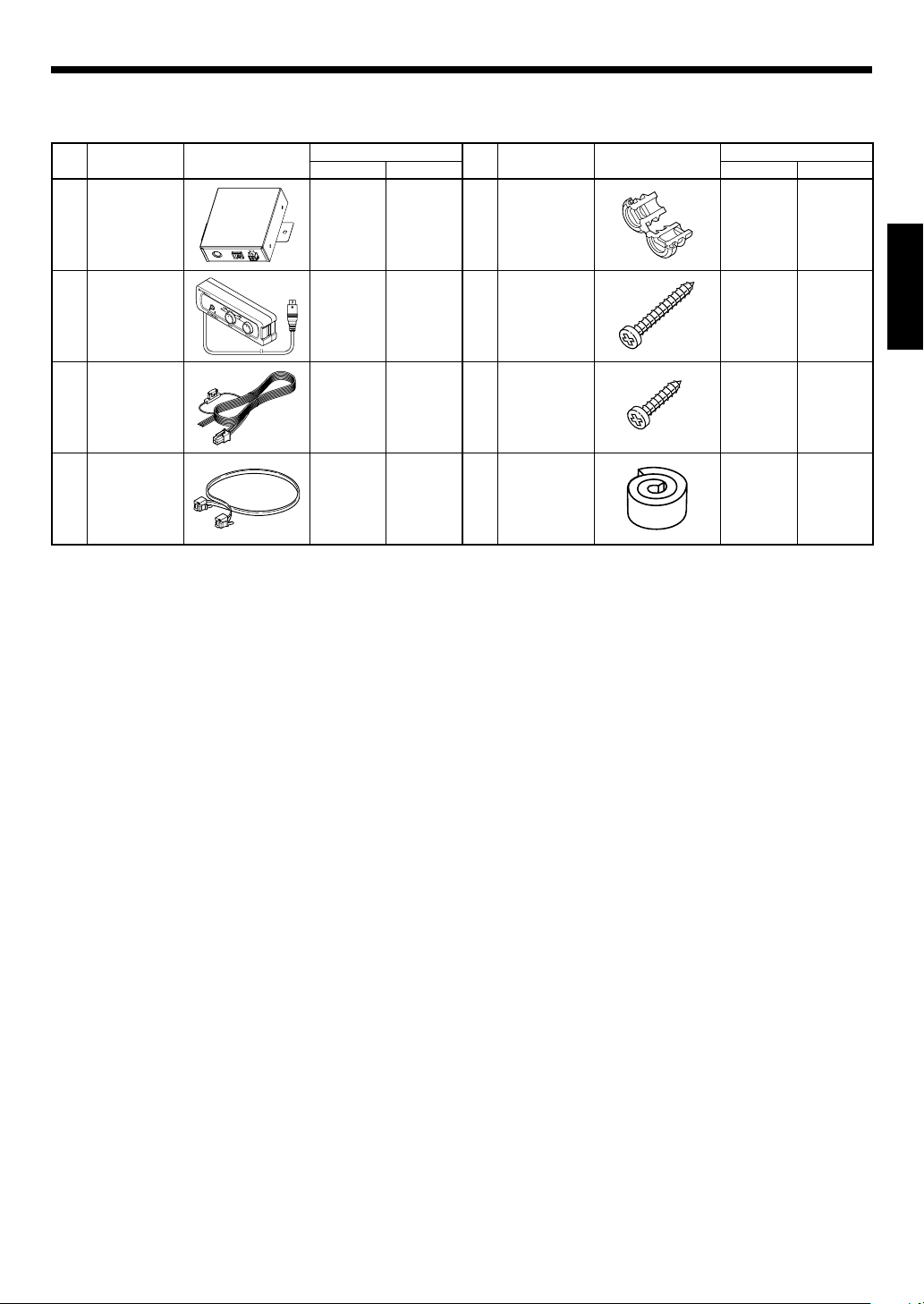
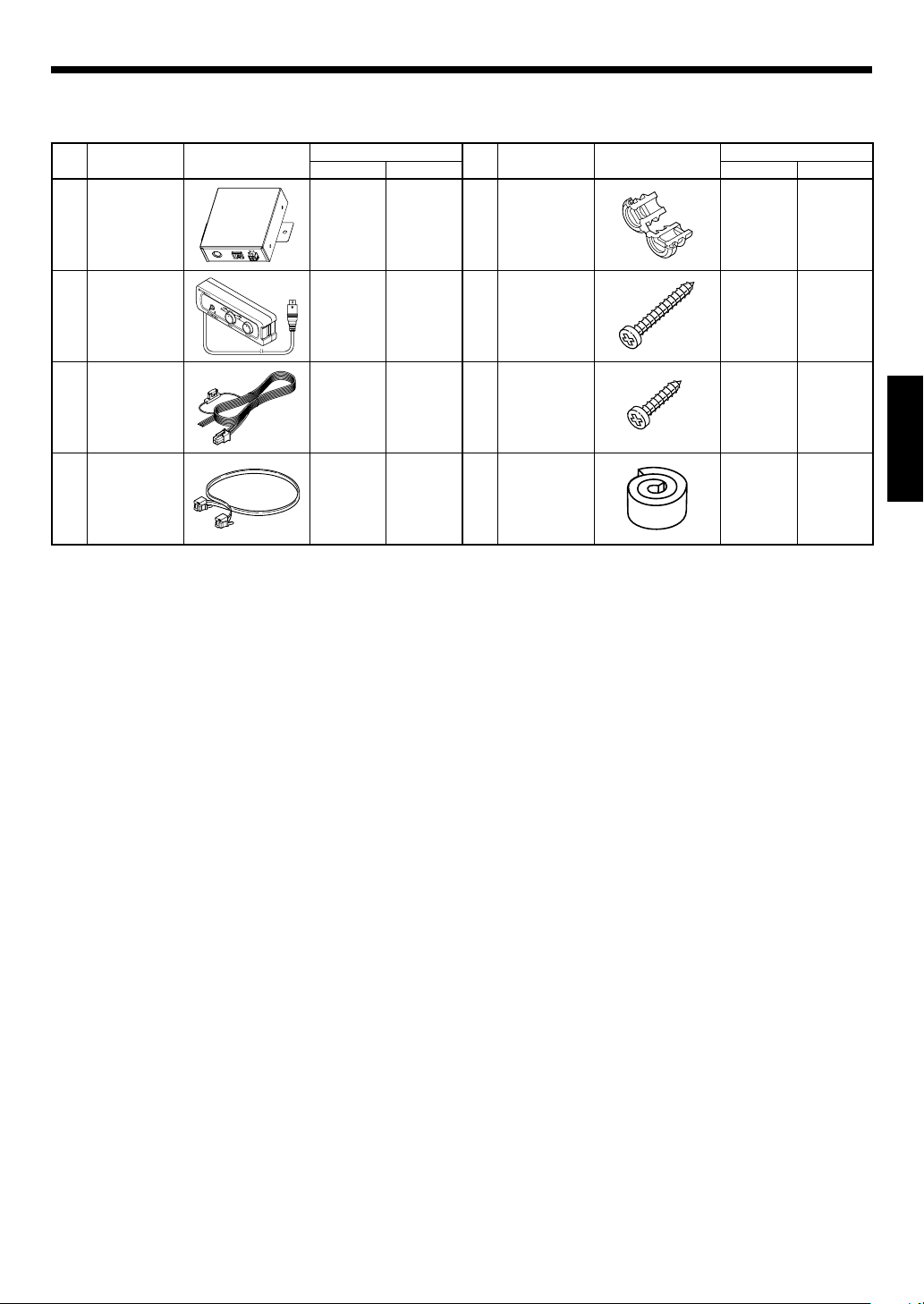
Parts included
Part Name Outside Shape
No.
Control box
1
Remote control
(Cord length:
2
6 m)
DC cable
(Cable length:
3
1.5 m)
Link cable
(Cable length:
4
1 m)
Quantity
KFC-W3000L
KFC-W3000LS
1–5Cord bush 11
1–
1–
118Cushion 11
Part Name Outside Shape
No.
Screw
6
(ø 4 x 35)
Screw
7
(ø 4 x 16)
Quantity
KFC-W3000L
KFC-W3000LS
88
2–
ENGLISH
English
3
Page 4
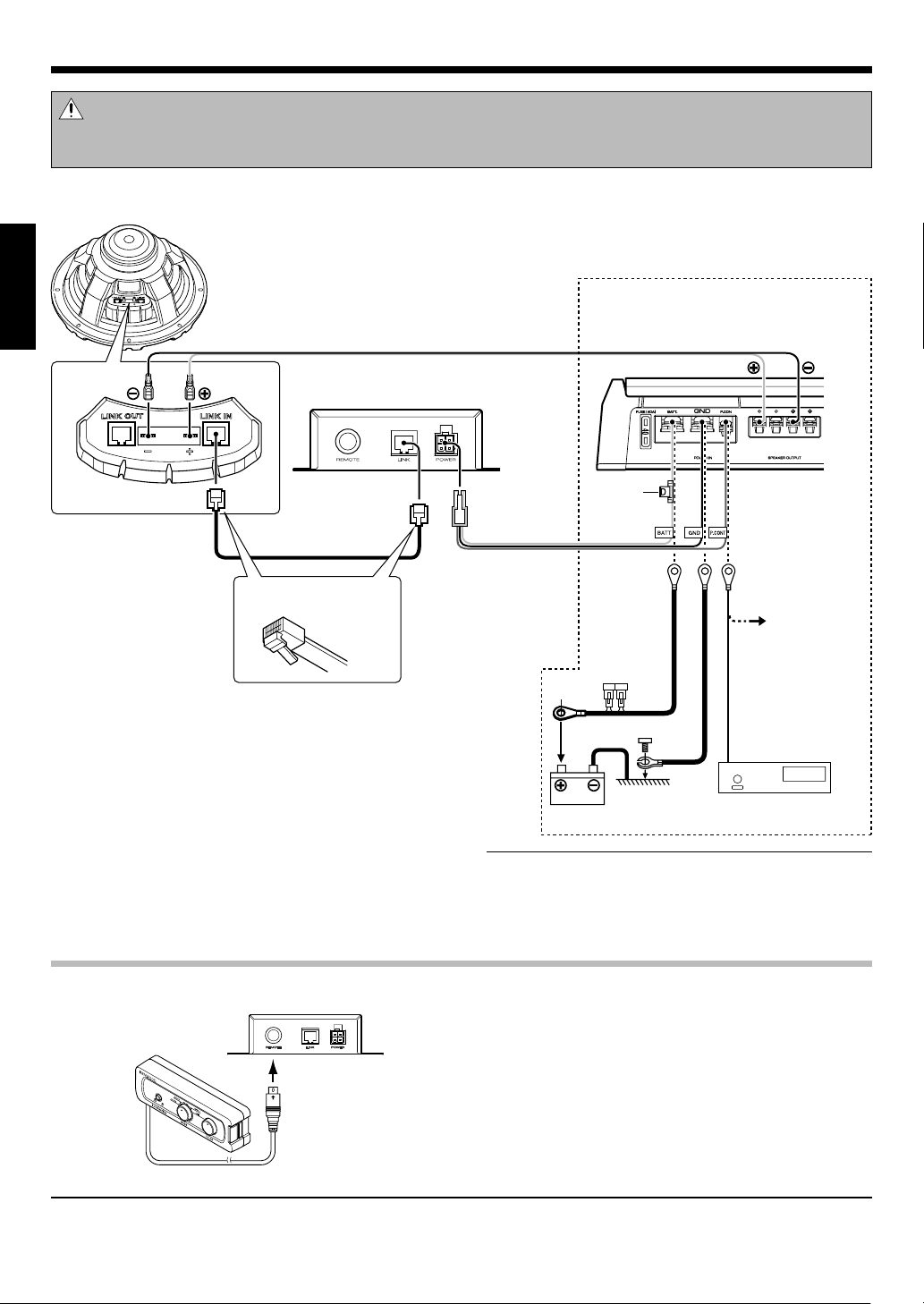
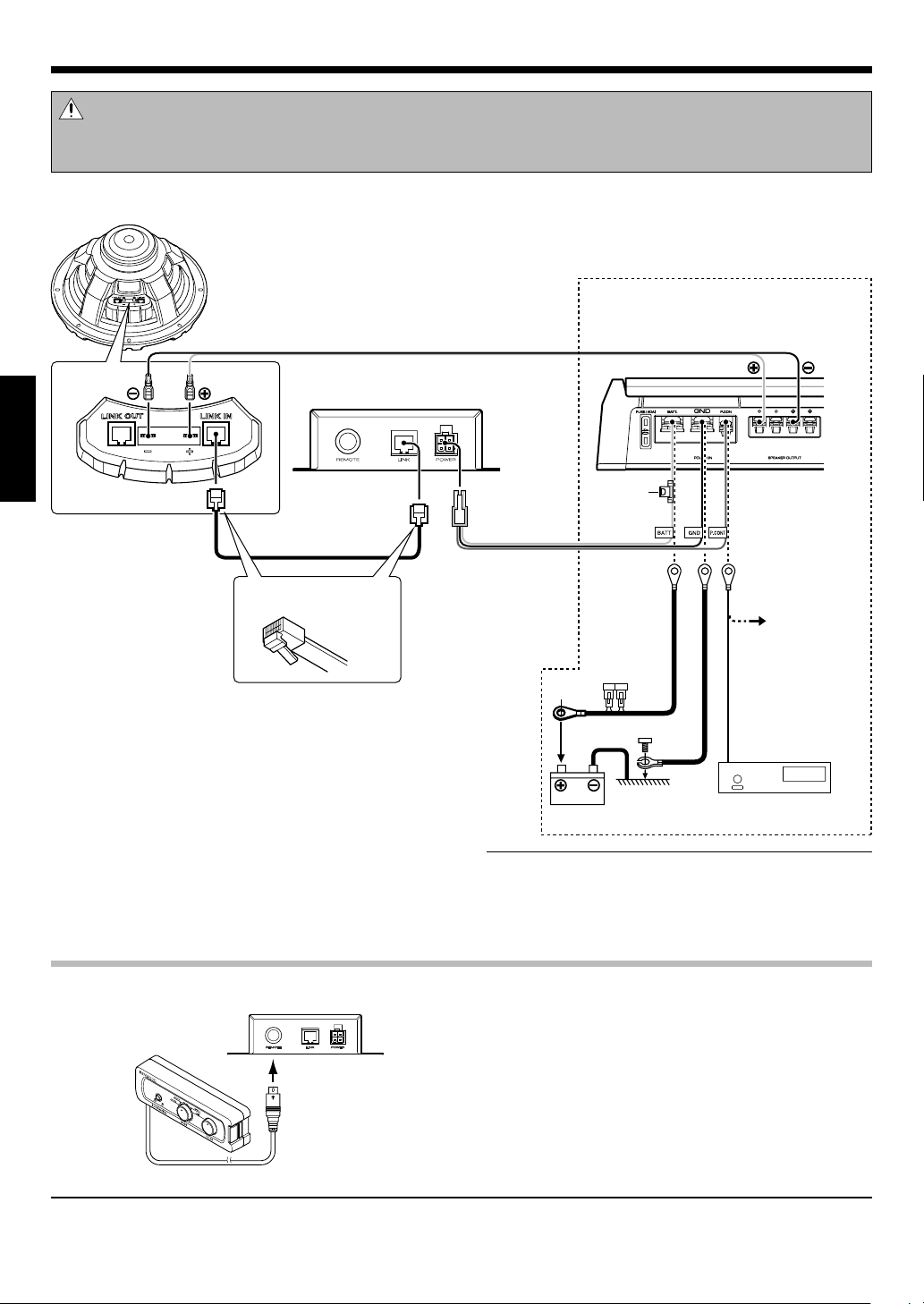
Connection
Caution:
Before wiring, be sure to remove the wire from the negative terminal of the battery. After completing all wiring, check the correct wirings
again. After checking, connect the wire from the negative terminal of the battery.
Woofer unit
(KFC-W3000L)
Amplifier is not included in this product.
ENGLISH
Speaker cord (Commercially available)
Control box
1
Please use a commer cially available ampli fier.
Link cable
4
Connect with the lock part of
LINK jack facing down.
Connect the POWER jack of the Control box 1
1
and amplifier using DC cable 3.
(If there is no power control terminal in the amplifier, connect to the accessory (ACC) line.)
Connect the LINK jack of the Control box 1 and
2
LINK IN jack of the Woofer unit using Link cable 4.
(A modular cable (commercially available) cannot
be used.)
Connect the amplifier and the Woofer unit with
3
speaker cords.
Connecting the remote control unitConnecting the remote control unit
Control box
1
Fuse (2A)
DC cable
3
BATT: Yellow
GND: Black
P.CO NT: Blue/ Wh it e
Battery
Notes:
• The illumination function cannot be used if the Link cable 4 is
connected erroneously to the LINK OUT jack of the Woofer unit.
Be sure to connect the Link cable 4 to the LINK IN jack.
• Do not plug or unplug the connection cables without switching
the power off. Otherwise, malfunction may result.
Center unit
Amplifier
If there is no
power control
terminal in the amplifier, connect the
blue/white wire to
the accessory line
(ignition key
switch ACC position line).
Connect the Remote control 2 to the REMOTE terminal of the Control box 1.
Remote control
2
Note:
The illumination function cannot be used when the Remote control 2 is not connected. Be sure to connect the Remote control 2 to the
Control box 1.
English
4
Page 5
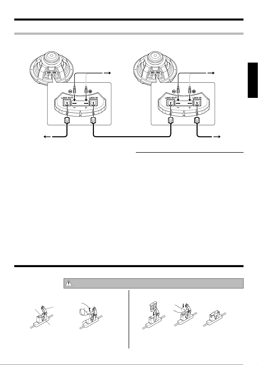
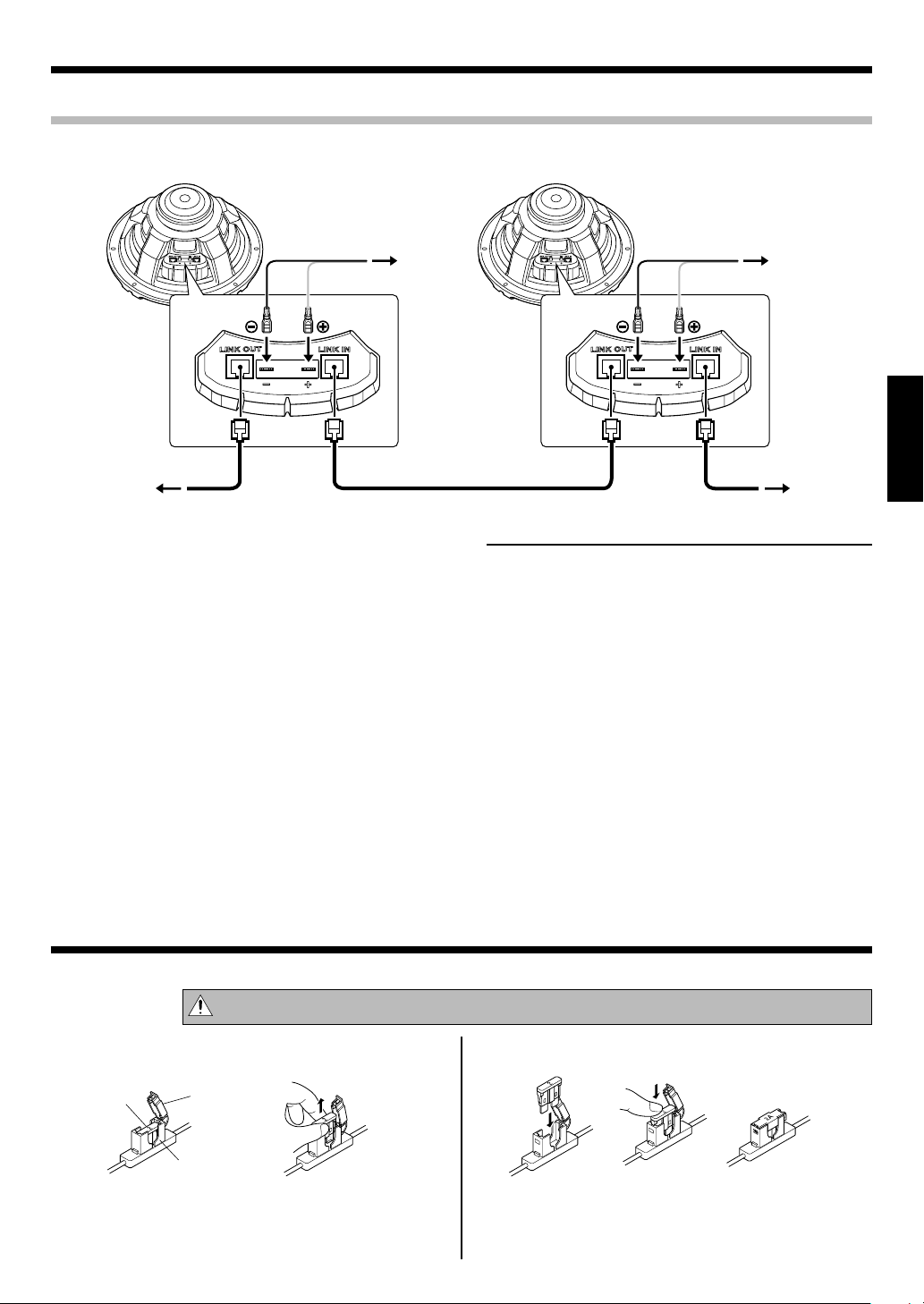
Connecting KFC-W3000L and KFC-W3000LS (KFC-W3000LS user only)
Woofer unit
(KFC-W3000LS)
Woofer unit
Woofer unit
Connect the LINK OUT jack of the Woofer unit 1
1
3
4
2
(KFC-W3000L) and LINK IN jack of the Woofer unit
(KFC-W3000LS) using Link cable 4.
2
Connect the amplifier and the Woofer unit with
2
speaker cords.
Link cable
4
Woofer unit
(KFC-W3000L)
Notes:
• The illumination function of the KFC-W3000LS is enabled only
when it is connected to the KFC-W3000L through the Link cable
.
4
The illumination function cannot be used when the KFC-
W3000LS is not connected to the KFC-W3000L.
• The maximum number of connected KFC-W3000LS units is 3
(the maximum total number of Woofer units including the KFCW3000L is 4).
• The illumination function cannot be used if the Link cable 4 is
connected erroneously to the LINK OUT jack of the Woofer unit
(KFC-W3000LS). Be sure to connect the Link cable 4 to the
2
LINK IN jack.
• The illumination is synchronized with the music signal input at
the speaker terminal of the Woofer unit 1 (KFC-W3000L).
The illuminations of the connected Woofer units 2, 3, 4 (KFC-
W3000LS) light according to the Woofer unit 1 (KFC-W3000L).
Note that they are not synchronized with the signals input to
them.
• Do not plug or unplug the connection cables without switching
the power off. Otherwise, malfunction may result.
1
AmplifierAmplifier
Control box
1
ENGLISH
Fuse exchange
Exchange with the specified capacity fuse.
Caution:
Removal Insertion
Fuse
Open the cover.
1
Grasp with pliers and pull up.
2
Cover
Fuse holder
Be sure to replace with same capacity (amperage) as displayed on the fuse. This product is 2A.
Replacement fuse 2A
Insert the fuse gently into the fuse holder and
1
push in all the way with your finger or tool.
Close the cover.
2
English
5
Page 6
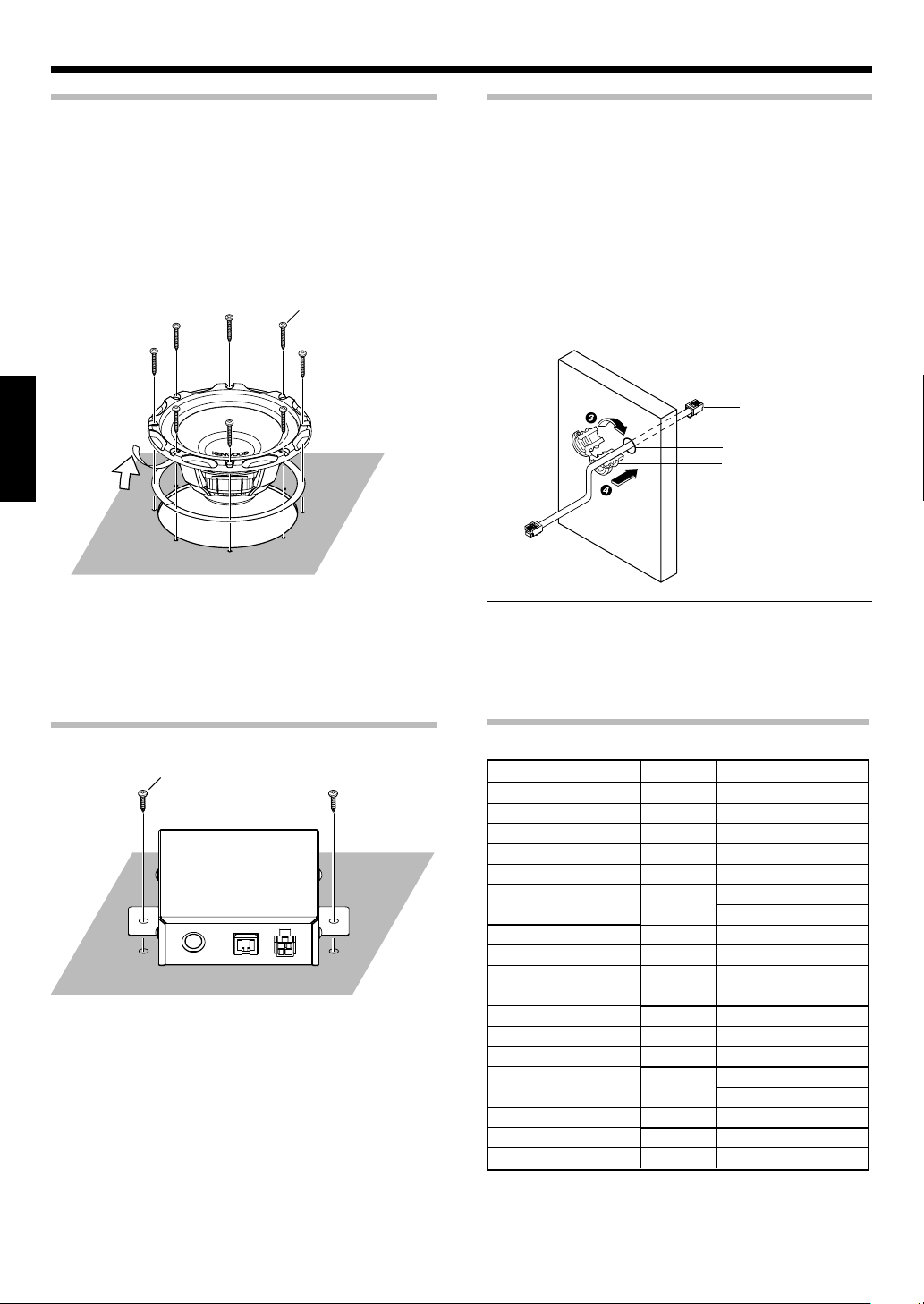
Installation
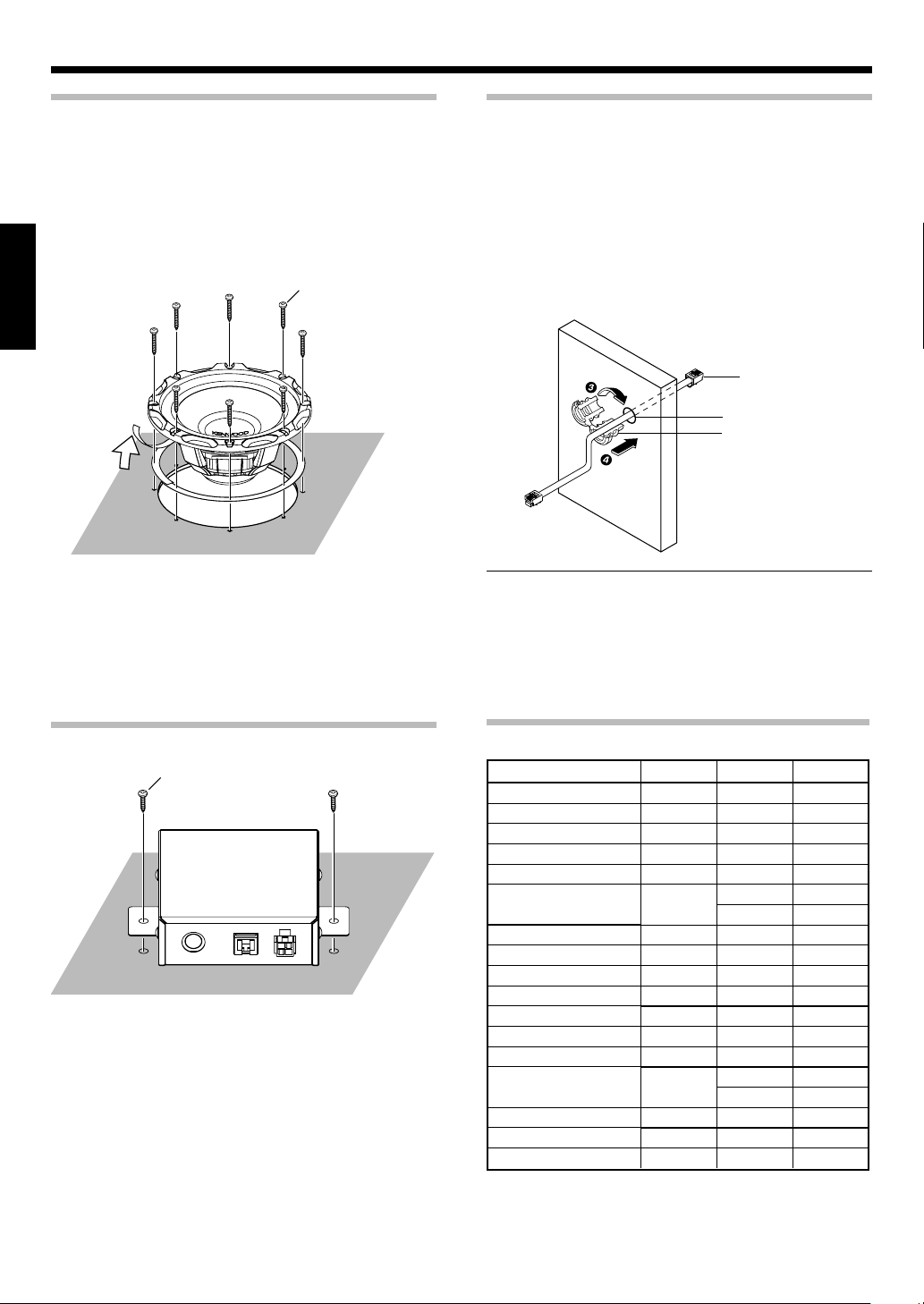
Fixing the SubwooferFixing the Subwoofer
Place the supplied template on the panel and
1
then mark the hole positions.
Cut open a large hole and make screw holes.
2
Peel off the covering sheet from the spacer, and
3
attach the spacer on the back of the speaker
flange so that the flange is completely covered.
Screw (ø 4 x 35) x 8
6
ENGLISH
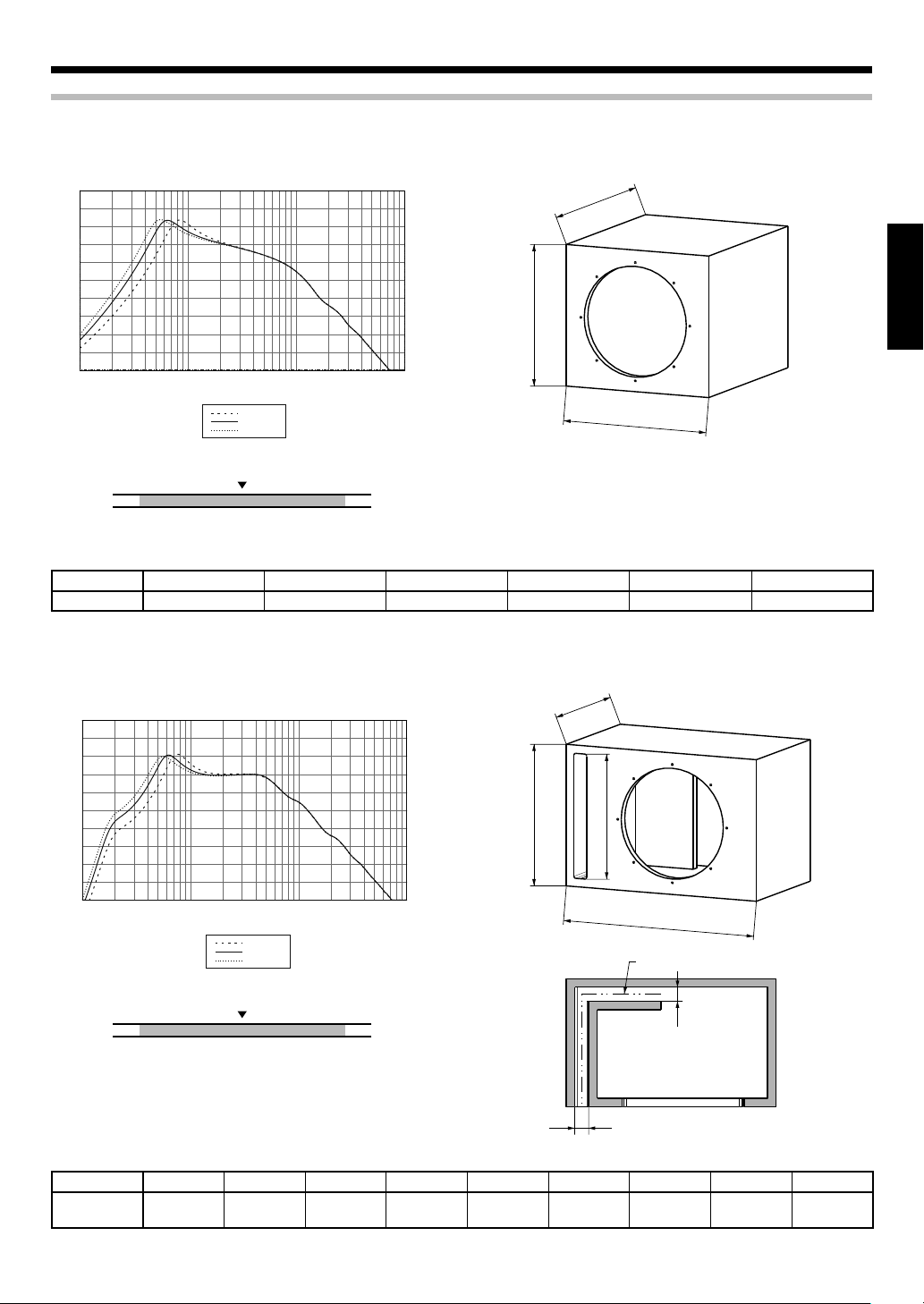
How to use the Cord bushHow to use the Cord bush
When you use a box for Woofer, use the attached Cord bush.
On the Woofer box, make a hole (ø 17.5) for fitting
1
the Cord bush 5.
Pass the Link cable 4 through the hole on the
2
Woofer box.
Attach the Cord bush 5 on an appropriate posi-
3
tion of the Link cable 4.
Push the Cord bush 5 into the hole on the Woofer
4
box.
Link cable
4
ø 17.5
Cord bush
5
Notes:
• Fit the Cord bush 5 firmly because clearance will lead to air
leak.
• Be careful not to pinch the Link cable 4 with the surface of the
Cord bush 5.
Fixing the Control boxFixing the Control box
Screw (ø 4 x 16) x 2
7
Technical specificationsTechnical specifications
SYMBOL UNIT VALUE
Nominal impedance
DC resistance
Voice coil inductance
Piston area
Force factor
Volume acoustic compliance
Moving mass
POWERREMOTE LINK
Resonance frequency
Mechanical Q factor
Electrical Q factor
Total Q factor
Peak power
Peak excursion
Displacement
Mounting depth
Weight of magnet
Voice coil diameter
ZΩ4
Revc Ω 3.4
Levc mH 0.56
Sd sq.m 0.052
BL T.m 9.53
Vas
Mms g 105.6
Fs Hz 30.9
Qms 9.59
Qes 0.77
Qts 0.71
Xmax mm 4.6
Liters 97.75
cu.ft 3.45
W 800
cc 5,190
cu.ft 0.183
mm (in.) 150 (5-7/8)
g (oz) 740 (26.1)
mm (in.) 50 (1-15/16)
6
English
Page 7
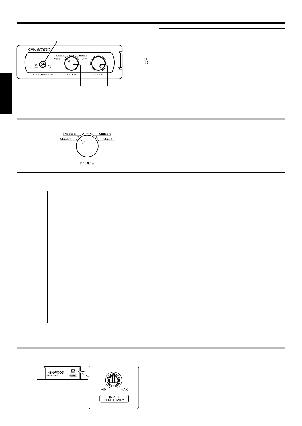
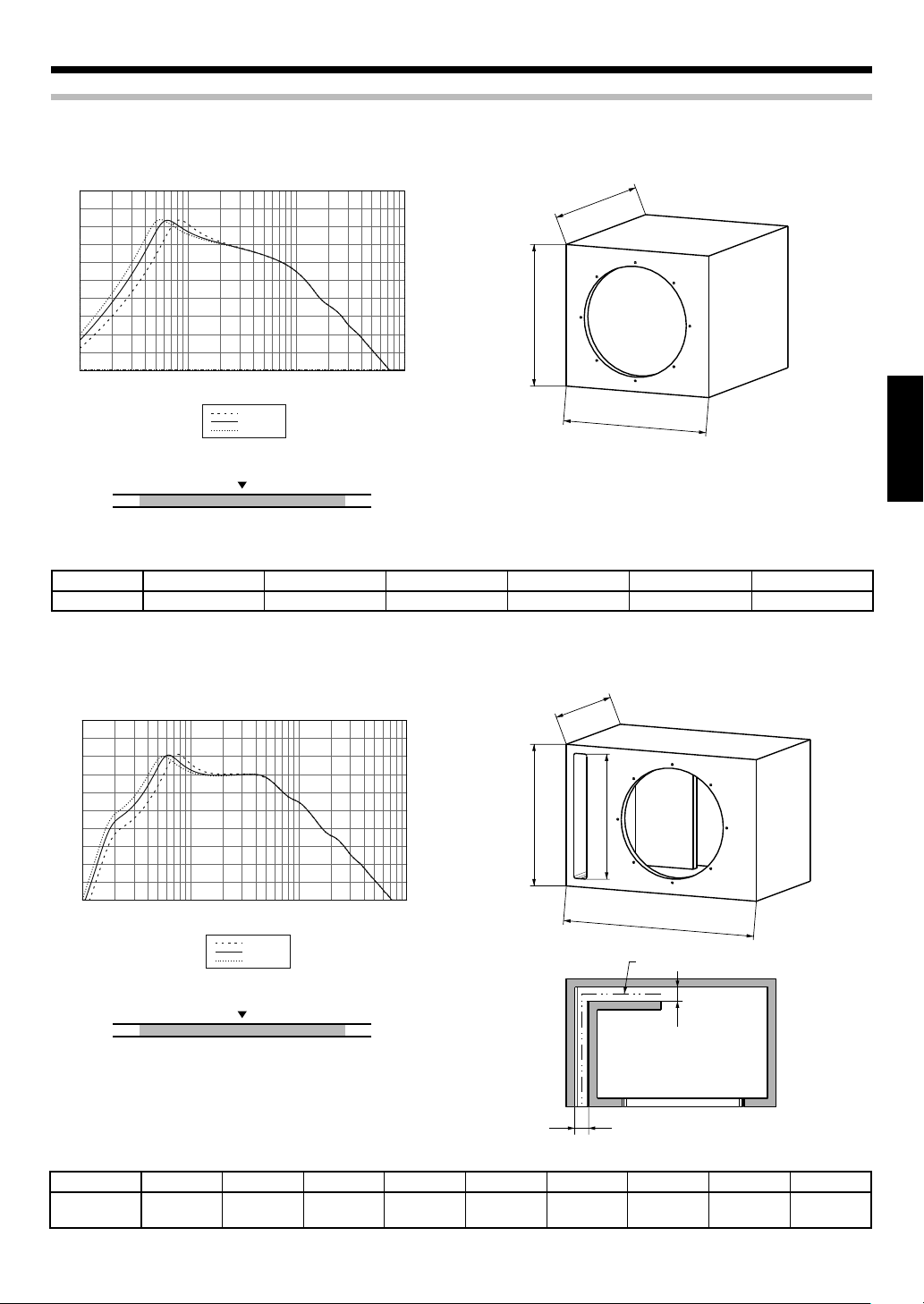
Recommended enclosuresRecommended enclosures
SEALED
95
90
85
80
75
70
65
60
RESPONSE (dB)
55
50
45
10
5020 100 200 500 1K 2K 5K 10K
FREQUENCY (Hz)
0.8 [cu.ft]
1.25 [cu.ft]
1.75 [cu.ft]
D
ENGLISH
H
W
tight bass
Recommended
deep bass
0.8 1.25 1.75
volume [cu.ft]
Type Inner Volume W H D
SEALED
1.25 cft (35.4 Liter) 375 mm (14-3/4") 370 mm (14-9/16") 355 mm (14") 282 mm (11-1/8") 0.11 cu.ft
Use 19 mm (3/4 inch) thick Medium Density Fiberboard (MDF) or High Density Particleboard.
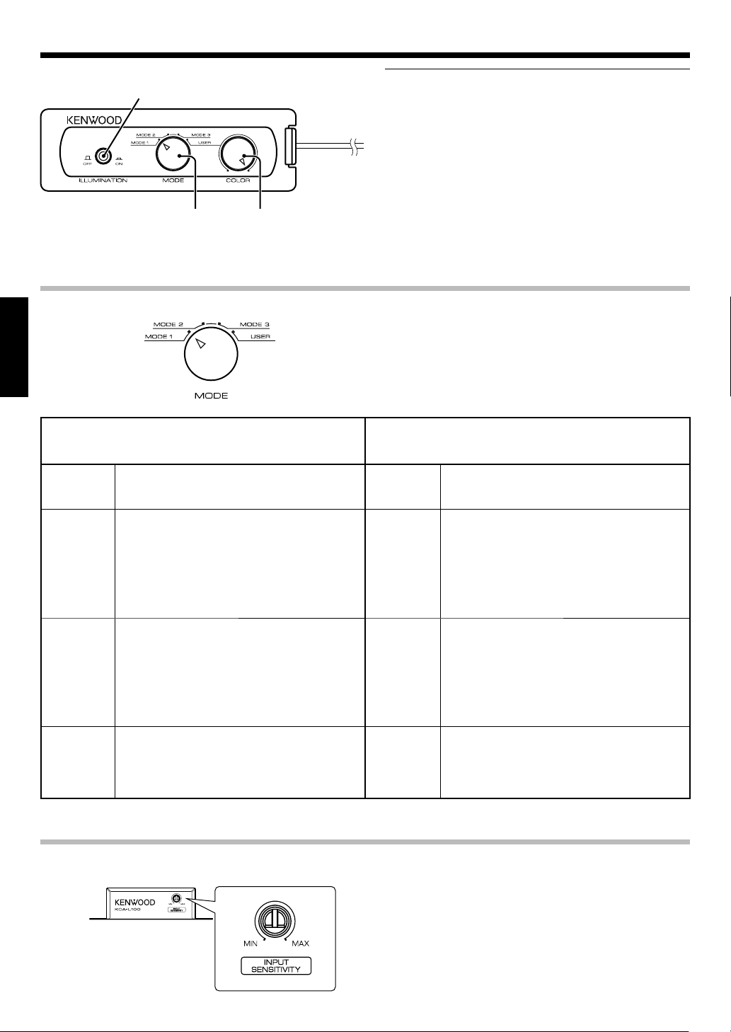
PORTED
95
90
85
80
75
70
65
60
RESPONSE (dB)
55
50
45
10
5020 100 200 500 1K 2K 5K 10K
FREQUENCY (Hz)
1.0 [cu.ft]
1.5 [cu.ft]
2.0 [cu.ft]
* W, H, D : External Dimensions
Mounting Hole Displacement
D
H
SH
W
SL
tight bass
Recommended
deep bass
1.0 1.5 2.0
volume [cu.ft]
Type Inner Volume W H D
PORTED
1.5 cft
(42.5 Liter)
507 mm
(19-15/16")
360 mm
(14-3/16")
320 mm
(12-5/8")
Mounting Hole
282 mm
(11-1/8")
Use 19 mm (3/4 inch) thick Medium Density Fiberboard (MDF) or High Density Particleboard.
SW
SW
* W, H, D : External Dimensions
SW SH SL
35 mm
(1-3/8")
322 mm
(12-11/16")
480 mm
(18-7/8")
Displacement
0.11 cu.ft
English
7
Page 8
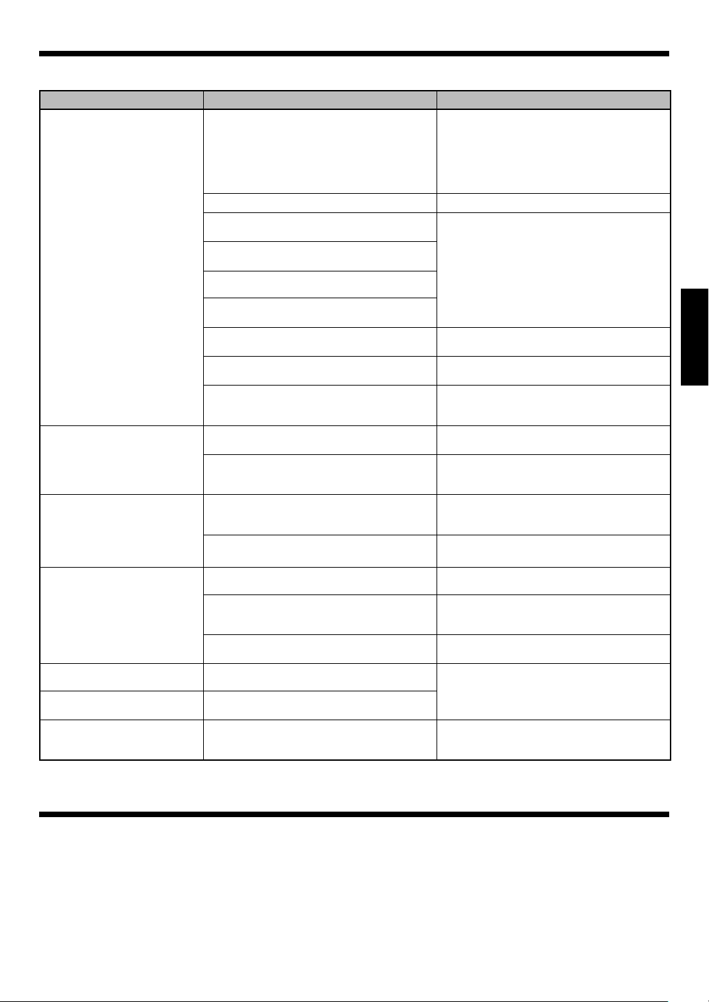
Operation
ILLUMINATION switch
Select whether or not the illumination is used.
ENGLISH
MODE selector
For each mode, refer
to the table described
below.
Color change volume
Used this knob in "USER" mode.
The color tone can be adjusted as desired.
Fully counterclockwise = White ←→ Red = Fully clockwise (Intermediate colors
available)
Changing the illumination modeChanging the illumination mode
On Music Mode
The On Music Mode is entered when a music signal is detected.
MODE 1 Cycle mode
Repeats MODE 2→MODE 3→USER→MODE 2...
Each mode changes every 20 seconds.
MODE 2 Variable mode
The illumination rotates along a circumference.
Illumination color changes depends on the signal
level.
Signal level low = Deep blue
high
You can adjust the illumination sensitivity with INPUT SENSITIVITY control knob.
MODE 3 Sound Link mode
The illumination lights in synchronism with music.
Illumination color changes depends on the signal
level.
Signal level low = White
You can adjust the illumination sensitivity with INPUT SENSITIVITY control knob.
USER User mode
The illumination lights in synchronism with music.
You can change the illumination color with Color
change volume. White
colors available)
←→
Red = Signal level
←→
Red = Signal level high
←→
Red (Intermediate
Notes:
• It is discommended to light the illuminations when the vehicle
is moving.
• Do not stare at the illumination light for a long period.
• Th e illuminati on func tion may malfunction if connectio ns
are erroneous. Be sure to connect the equipment properly by
referring to "Connection" in this manual (on page 4, 5).
Turn the MODE selector knob to select the illumination mode. Each mode (MODE 1, 2, 3 or USER)
changes depends on whether the music signal is
existing or not.
Off Music Mode
The Off Music Mode is entered when no music signal has been
input for 20 seconds.
MODE 1 Cycle mode
Repeats MODE 2→MODE 3→USER→MODE 2...
Each mode changes after it has been played twice.
MODE 2 Variable mode
The illumination flows from the top to the bottom.
MODE 3 Quiet mode
USER User mode
White lights slowly.
The selected color lights slowly.
You can change the illumination color with Color
change volume. White
colors available)
←→
Red (Intermediate
Adjusting the illumination sensitivityAdjusting the illumination sensitivity
Control box
1
English
8
In the "On Music Mode", you can adjust the illumination sensitivity.
Turn the INPUT SENSITIVITY control knob using a
minus driver to adjust the illumination sensitivity
as desired.
Page 9

Troubleshooting guide
Often, what appears to be a malfunction is due to user error. Before calling for service, please consult the following table.
Problem Cause Remedy
• The fuse is blown. • Check the (+)/(-) polarity of the power cord
• The remote control cord is unplugged. • Plug the cord into the REMOTE terminal.
• The power sup ply pin (yellow) o f the DC
cable is not connected.
• The power control pin (blue/white) of the
DC cable is not connected.
Illumination does not light.
Illumination is not
synchronized with the sound.
The illumination color does
not change.
No sound
Sound is small. • The input level is set to low.
Sound quality is bad (sound
is distorted).
Sound is unnatural.
• The DC cable is not plugged in completely.
• The grounding pin (black) of the DC cable is
not connected.
• The negative (-) cable of the car battery is
disconnected.
• The ON/OFF switch of the remote control
unit is set to OFF.
• The Link cable is connected improperly. • Connect the cords correctly by referring to
• No audio signal is input to the speaker. • Connect the cords correctly by referring to
• Speaker's volume is low. • Adjust with the INPUT SENSITIVITY control
• Speaker's volume is high. • Adjust with the INPUT SENSITIVITY control
• The MODE selector is set to "USER". • Turn the MODE selector to MODE 1, 2, or 3 (on
• The attenuator of the center unit is set to
ON.
• The speaker cords are connected improperly.
• Connec tion terminals are conne cted im properly.
• The input level is set to high.
• The speaker cords are connected with incorrect positive (+)/negative (-) polarity.
and that the cords are not shorted, then replace with a fuse with the rated capacity.
• Re-connect the cords correctly by referring
to the connection example (on page 4, 5).
• Connect the cord correctly by referring to
the connection example (on page 4, 5).
• Check th e conne cti ons of al l cords, then
connect the (-) cable to the battery.
• Insert the connector all the way in.
• Attach the grounding terminal to the metallic section of the vehicle (not a coated surface) by tightly screwing it.
• Check th e conne cti ons of al l cords, then
connect the (-) cable to the battery.
• Switch the ON/OFF switch to ON.
the connection example (on page 4, 5).
• Insert the connector all the way in.
the connection example (on page 4, 5).
kn ob of the Control box clo ckw ise (MA X
side) (on page 8).
knob of the Control box counter-clockwise
(MIN side) (on page 8).
page 8).
• Switch the attenuator OFF.
• Connect the cords correctly by referring to
the connection example (on page 4, 5).
• Insert the connectors or jacks all the way in
to the terminals.
• Adjust the volume of the Center unit.
• Connect the cords correctly by referring to
the connection example (on page 4, 5).
ENGLISH
Specifications
The following ratings and design are subject to change without notice.
[Speaker unit]
Subwoofer ......................... 300 mm (12 in.) Injection PP Cone
740 g (26.1 oz) Magnet
Peak input power ............................................................. 800 W
Maximum input power .................................................... 400 W
Rated input power ........................................................... 200 W
Frequency response ................................................ 28 - 800 Hz
Sensitivity .........................................................90 dB / W at 1 m
Rated impedance .................................................................. 4 Ω
[Control unit]
Operating voltage .............. DC 14.4 V (10.5 ~ 16 V allowable)
Maximum current consumption .................................. 150 mA
Fuse capacity ..........................................................................2 A
English
9
Page 10
CONSIGNES DE SÉCURITÉ IMPORTANTES
Attention : Lire attentivement cette page pour garantir une exploitation sans danger.
ATTENTION DANGER ATTENTION DANGER
• Avant d'effectuer le montage ou le câblage, etc., assurez-vous
de débrancher la borne négative de la batterie.
(Dans le cas contraire, vous risquez de déclencher un court-
circuit ou un incendie)
• Pour éviter tout court-circuit, n’introduisez jamais un objet métalliaque (pièces de monnaie, outils) dans un appareil.
• Dans le cas oû l’appareil produit de la fumée ou une odeur anormale, couper immédiatement l’alimentation. Contacter ensulte
votre concessionnaire ou centre de service plus proche le plus
rapidement possible.
COUPER L’ALIMENTATION!
• Raccorder les hautparleurs munis de la lampe d’illumination sur
12 V CC, mise à la terre négative.
• Ne pas essayer de démonter ni de modifier l’apparell car ceci risque de provoquar un risque d’incendie ou un fonctionnement
incorrect.
• Après avoir retré l’appareil du sac de polyéthylàne, bien placer
ce dernier hors de la portée des enfants. S’ils jouent avec ce sac,
un risque d’étouffement est possible.
FRANÇAIS
ATTENTION ATTENTION
• L’installation et le câblage de ce produit exigent des connaissances et une expérience professionnelles. Pour des raisons de
sécurité, l’installation et le câblage doivent être effectués par le
revendeur de ce produit ou par un spécialiste.
• N’installez pas le haut-parleur dans un endroit directement exposé au soleil ou à une humidité ouchaleur excessives.
• Ne pas installer les haut-parieurs dans des endroits où ils peuvent être exposés à de l’eau ou à l’humidité.
• Ne pas installer les haut-parteurs dans de endroits instables ou
exposés à de la poussière.
• Si le fusible grille, assurez-vous de le remplacer, après avoir vérifié que le câblage n’est pas en court-circuit, par un fusible du
calibre spécifié (ampérage) sur le boîtier.
(L’utilisation de fusible de calibre supérieur peut causer un in-
cendie)
Vèrifiez L'affichage !
Pour le remplacement de fusible, consultez le manuel d’utilisa-
tion du véhicule.
• Avant de remplacer le fusible et pour éviter tout court-circuit,
débranchez le faisceau.
• N’utilisez ni essence, ni pétrole ni aucun solvant pour nettoyer le
haut parleur. Utilisez un chiffon doux et sec.
• Reliez séparément les cordons de liaison des haut-parleurs aux
bornes convenables. Une liaison commune du cordon relié à la
borne négative, ou la mise à la masse de la carrosserie de ces
cordons peuvent entraîner une anomalie de fonctionnement.
• Avant de percer un t rou sous un siège, dans le cof fre et, d’
une manière générale, en n’importe quel point du véhicule,
assurez-vous que vous pouvez le faire sans danger et que votre
intervention ne conduira pas à l’endommagement du réservoir
de carburant, d’une canalisation de frein ou d’un faisceau électrique; veillez également à ne pas effectuer de rayures ou d’
autres dommages inutiles.
• Pour le raccordement à la masse, ne pas fixer le fil à un airbag, au
système de direction, à une ligne du système de freinage ou à
tout autre boulon ou écrou critique en terme de sécurité.
(Risque d’accident).
• Pour l’installation, choisissez un emplacement qui ne présente
aucune gêne pour la conduite du véhicule ou un danger pour
les passagers lors de freinages soudains, etc.
(Risque de blessure ou d’accident)
• Apès installation assurez-vous que les équipements électriques
tels que les feux stop, les feux clignotants et les essuieglace
fonctionnent toujours normalement.
• Le conducteur devrait toujours arrêter le véhicule en lieu sûr
avant d’effectuer l’opération suivante.
– Utiliser la télécommande
• Ce produit ne doit être utilisé que dans une installation
embarquée.
Information sur l’élimination des anciens
équipements électriques et électroniques
(applicable dans les pays de l’Union Européenne qui ont adopté des systèmes de collecte
sélective)
Les produits sur lesquels le pictogramme (poubelle
barrée) est apposé ne peuvent pas être éliminés
comme ordures ménagères.
Les anciens équipements électriques et électroniques
doivent être recyclés sur des sites capables de traiter
ces produits et leurs déchets. Contactez vos autorités locales
pour connaître le site de recyclage le plus proche. Un recyclage
adapté et l’élimination des déchets aideront à conserver les ressources et à nous préserver des leurs effets nocifs sur notre santé
et sur l’environnement.
Déclaration de conformité se
rapportant à la directive EMC
2004/108/EC
Fabricant:
Kenwood Corporation
2967-3 Ishikawa-machi, Hachioji-shi, Tokyo,
192-8525 Japon
Représentants dans l'UE:
Kenwood Electronics Europe BV
Amsterdamseweg 37, 1422 AC UITHOORN,
Pays-Bas
Pour le Canada
REMARQUE: Cet appareil numérique de la classe B est conforme à
la norme NMB-003 du Canada.
2
Français
Page 11
Fournitures
Désignation
No.
des pièces
Boîte de
1
commande
Tél éco mma nde
(Longueur du
2
cordon: 6 m)
Câble CC
(Longueur du
3
câble: 1,5 m)
Câble de liaison
(Longueur du
4
câble: 1 m)
Forme extérieure
Quantité
KFC-W3000L
KFC-W3000LS
1–
1–
1–
118Coussin 11
No.
5
6
7
Manchon de
câble
Vis
(ø 4 x 35)
Vis
(ø 4 x 16)
Désignation
des pièces
Forme extérieure
Quantité
KFC-W3000L
KFC-W3000LS
11
88
2–
FRANÇAIS
Français
3
Page 12
Connexions
Attention:
Avant d’effectuer le câblage, détachez le câble de la borne négative de la batterie. Lorsque le câblage est terminé, vérifiez si les câbles sont tous
bien raccordés. À ce moment seulement, rebranchez le câble sur la borne négative de la batterie.
Haut-parleur de graves
(KFC-W3000L)
L’amplificateur n’est pas f ourni avec ce produit.
Procurez-vous un amplif icateur dans le c ommerce.
Cordon d'enceinte (Vendu séparément)
Boîte de commande
1
FRANÇAIS
Câble de liaison
4
Raccordez avec l’onglet d’arrêt de
la prise LINK orienté vers le bas.
Raccordez la prise POWER de la boîte de com-
1
mande 1 et l’amplificateur avec le câble CC 3.
(S’il n’y a pas de prise de commande d’alimentation sur l’amplificateur, raccordez le câble à la
prise de ligne accessoire (ACC).)
Raccordez la prise LINK de la boîte de commande
2
et la prise LINK IN du haut-parleur de graves
1
avec un câble de liaison 4.
(Ne pas utiliser de câble modulaire (en vente
dans le commerce).)
Raccordez l’amplificateur et le haut-parleur de
3
graves avec les cordons d’enceintes.
Raccordement de la télécommandeRaccordement de la télécommande
Boîte de commande
1
Fusible (2A)
Câble CC
3
BATT: Jaune
GND: Noir
P.CO NT: Bleu/Blanc
Batterie
Remarques:
• L’éclairage ne pourra pas être utilisé si le câble de liaison 4 est raccordé
par erreur à la prise LINK OUT du haut-parleur de graves. Veillez à raccorder
le câble de liaison 4 à la prise LINK IN.
• Ne branchez pas ou ne débranchez pas les câbles de liaison sans avoir mis
au préalable les appareils hors tension. Cela peut provoquer une panne.
Amplificateur
Si l'amplificateur
ne comporte
pas de borne
de commande
d'alimentation, connectez les fils bleu
et blanc à la ligne
pour accessoires
(alimentée lorsque
la clef de contact
est placée sur ACC).
Unité centrale
Raccordez la télécommande 2 à la borne REMOTE de
la boîte de commande 1.
Tél écom mande
2
Remarque:
L’éclairage ne pourra pas être utilisé si la télécommande 2 n’est pas raccordée. Veillez à raccorder la télécommande 2 à la boîte de commande 1.
Français
4
Page 13
Raccordement des KFC-W3000L et KFC-W3000LS (Utilisateur du KFC-W3000LS seulement)
Haut-parleur de graves
(KFC-W3000LS)
Haut-parleur de
graves
3
Haut-parleur de
graves
4
Raccordez la prise LINK OUT du haut-parleur de
1
2
graves 1 (KFC-W3000L) et la prise LINK IN du
haut-parleur de graves 2 (KFC-W3000LS) avec le
câble de liaison 4.
Raccordez l’amplificateur et le haut-parleur de
2
graves avec les cordons d’enceintes.
Câble de liaison
4
Remarques:
• L’éclairage du KFC-W3000LS est disponible lorsque le KFC-W3000LS
L’éclairage ne peut pas être utilisé lorsque le KFC-W3000LS n’est
• Le nombre maximal de haut-parleurs de graves KFC-W3000LS
• L’éclairage ne peut pas être utilisé si le câble de liaison 4 est rac-
• L’éclairage se synchronise sur le signal de musique présent à la
Les éclairages des haut-parleurs de graves raccordés 2, 3, 4
• Ne branchez pas ou ne débranchez pas les câbles de liaison
Haut-parleur de graves
(KFC-W3000L)
est raccordé au KFC-W3000L par le câble de liaison 4.
pas raccordé au KFC-W3000L.
est limité à 3 (le nombre maximal de haut-parleurs de graves,
KFC-W3000L compris, est limité à 4).
cordé par erreur à la prise LINK OUT du haut-parleur de graves
(KFC-W3000LS). Veillez à raccorder le câble de liaison 4 à la
2
prise LINK IN.
borne du haut-parleur de graves 1 (KFC-W3000L).
(KFCW3000LS) s’allument en fonction du haut-parleur de graves
(KFC-W3000L). Ils ne se synchronisent pas sur les signaux qui
1
leurs sont envoyés.
sans avoir mis au préalable les appareils hors tension. Cela peut
provoquer une panne.
1
AmplificateurAmplificateur
Boîte de
1
commande
FRANÇAIS
Remplacement de fusible
Remplacez le fusible défectueux par un autre du calibre spécifié.
Attention: Ne remplacer le fusible que par un autre du même calibre (ampérage) marqué dessus. 2A dans ce cas.
Retrait Insertion
Fusibl e
Ouvrez le couvercle.
1
Saisissez avec des pinces et tirez.
2
Couvercle
Support de fusible
Fusible de rechange de 2A
Insérez le fusible doucement dans le porte-fus-
1
ible et enfoncez-le bien avec le doigt ou un outil.
Fermez le couvercle.
2
Français
5
Page 14
Installation
Fixation du caisson d’extrême graveFixation du caisson d’extrême grave
Placer le gabarit fourni sur le panneau et marquer
1
les positions des trous.
Découper un trou de grande dimension et percer
2
trous pour les vis.
Retirez la feuille de protection placée sur la
3
bande et fixez cette bande sur le bord arrière du
haut-parleur de manière qu'il soit entièrement
couvert.
Vis (ø 4 x 35) x 8
6
FRANÇAIS
Comment utiliser le manchon de câbleComment utiliser le manchon de câble
Si vous utilisez un caisson pour le haut-parleur de graves, rattachez le manchon au câble.
Sur le caisson de graves percez un orifice (ø 17,5)
1
pour insérer le manchon de câble 5.
Faites passer le câble de liaison 4 par l’orifice
2
dans le caisson de graves.
Fixez le manchon de câble 5 à la bonne position
3
du câble de liaison 4.
Insérez le manchon de câble 5 dans l’orifice du
4
caisson de graves.
Câble de liaison
4
ø 17,5
Manchon de câble
5
Remarques:
• Coincez bien le manchon de câble 5 de manière à ce qu’il ne
bouge pas et ne laisse pas passer de l’air.
• Faites attention toutefois de ne pas coincer le câble de liaison 4
dans le joint du manchon 5.
Fixation de la boîte de commandeFixation de la boîte de commande
Vis (ø 4 x 16) x 2
7
POWERREMOTE LINK
Caractéristiques techniquesCaractéristiques techniques
SYMBOLE UNITÉ VALEUR
Impédance nominale
Résistance CC
Inductance de la bobine acoustique
Surface du piston
Facteur de force
Élasticité acoustique
Masse en déplacement
Fréquence de résonance
Facteur Q mécanique
Facteur Q électrique
Facteur Q total
Puissance maximale
Déviation maximal
Déplacement
Profondeur de montage
Poids de l’aimant
Diamètre de la bobine acoustique
ZΩ4
Revc Ω 3,4
Levc mH 0,56
Sd sq.m 0,052
BL T.m 9,53
Vas
Mms g 105,6
Fs Hz 30,9
Qms 9,59
Qes 0,77
Qts 0,71
Xmax mm 4,6
Liters 97,75
cu.ft 3,45
W 800
cc 5.190
cu.ft 0,183
mm (in.) 150 (5-7/8)
g (oz) 740 (26,1)
mm (in.) 50 (1-15/16)
6
Français
Page 15
Caissons recommandésCaissons recommandés
HERMÉTIQUE
95
90
85
80
75
70
65
60
RESPONSE (dB)
55
50
45
10
5020 100 200 500 1K 2K 5K 10K
FREQUENCY (Hz)
0.8 [cu.ft]
1.25 [cu.ft]
1.75 [cu.ft]
D
H
FRANÇAIS
W
Basses serrées
Recommandé
Basses profondes
0,8 1,25 1,75
Volume [cu.ft]
Type Volume intérieur W H D
HERMÉTIQUE
1,25 cft (35,4 Litre) 375 mm (14-3/4") 370 mm (14-9/16") 355 mm (14") 282 mm (11-1/8") 0,11 cu.ft
Utilisez un panneau en fibre de moyenne densité 19 mm (3/4 pouce) (MDF) ou un panneau en aggloméré haute densité.
À ÉVENT
95
90
85
80
75
70
65
60
RESPONSE (dB)
55
50
45
10
5020 100 200 500 1K 2K 5K 10K
FREQUENCY (Hz)
1.0 [cu.ft]
1.5 [cu.ft]
2.0 [cu.ft]
D
H
SH
* W, H, D : Dimensions externes
Orifice de montage Déplacement
W
SL
Basses serrées
Recommandé
Basses profondes
1,0 1,5 2,0
Volume [cu.ft]
SW
Type
À ÉVENT
Volume intérieur
1,5 cft
(42,5 Litre)
WHD
507 mm
(19-15/16")
360 mm
(14-3/16")
320 mm
(12-5/8")
Orifice de montage
282 mm
(11-1/8")
SW SH SL
35 mm
(1-3/8")
Utilisez un panneau en fibre de moyenne densité 19 mm (3/4 pouce) (MDF) ou un panneau en aggloméré haute densité.
SW
322 mm
(12-11/16")
* W, H, D : Dimensions externes
Déplacement
480 mm
(18-7/8")
0,11 cu.ft
Français
7
Page 16
Fonctionnement
Commutateur ILLUM INATION
Précisez si l ’éclairage doit être ou non utilisé.
Sélecteur MODE
Pour chaque mode,
reportez-vous au
tableau ci-dessous.
Bouton de changement des couleurs
Utilisez ce bouton en mode “USER”.
Le ton de la couleur peut être ajusté comme vous le souhaitez.
Complètement antihoraire = Blanc ←→ Rouge = Complètement horaire (Couleurs
intermédiaires disponibles)
Changement du mode d’éclairageChangement du mode d’éclairage
FRANÇAIS
Mode Musique en service
Vous accédez a u mode Mu sique e n ser vice lo rsqu’un sig nal
musical est détecté.
MODE 1 Mode Cycle
Répète MODE 2→MODE 3→USER→MODE 2...
Chaque mode change toutes les 20 secondes.
MODE 2 Mode Variable
L’éclairage tourne en un cercle.
La couleur de l’éclairage change selon le niveau du
signal.
Niveau du signal faible = Bleu foncé
Niveau du signal élevé
Vous pouvez régler la sensibilité de l’éclairage avec
le bouton de commande INPUT SENSITIVITY.
MODE 3 Mode Liaison sonore
L’éclairage s’allume en même temps que la musique.
La couleur de l’éclairage change selon le niveau du
signal.
Niveau du signal faible = Blanc
du signal élevé
Vous pouvez régler la sensibilité de l’éclairage avec
le bouton de commande INPUT SENSITIVITY.
USER Mode Utilisateur
L’éclairage s’allume en même temps que la musique.
Vous pouvez changer la couleur de l’éclairage avec
le bouton de changement de couleur. Blanc
Rouge (Couleurs intermédiaires disponibles)
←→
←→
Rouge = Niveau
Rouge =
←→
Remarques:
• Il est déconseillé de faire fonctionner l’éclairage pendant la
conduite du véhicule.
• Ne regardez pas l’éclairage pendant longtemps.
• L’éclairage peut mal fonctionner si les connexions sont erronées.
Veillez à raccorder l’appareil convenablement en vous référant à
"Connexions" dans ce manuel (pages 4, 5).
Tournez le sélecteur MODE pour sélectionner le
mode d’éclairage souhaité. Chaque mode (MODE
1, 2, 3 ou USER) change selon la présence ou l’absence du signal musical.
Mode Musique hors service
Le mode Musique hors service s’active si aucun signal musical n’
est fourni durant 20 secondes.
MODE 1 Mode Cycle
Répète MODE 2→MODE 3→USER→MODE 2...
Chaque mode change lorsqu’il a été joué deux fois.
MODE 2 Mode Variable
L’éclairage effectue un mouvement du haut vers le
bas.
MODE 3 Mode Silencieux
USER Mode Utilisateur
Le blanc s’allume lentement.
La couleur sélectionnée s’allume lentement.
Vous pouvez changer la couleur de l’éclairage avec
le bouton de changement de couleur. Blanc
Rouge (Couleurs intermédiaires disponibles)
←→
Réglage de la sensibilité de l’éclairageRéglage de la sensibilité de l’éclairage
Boîte de commande
1
Français
8
Dans le "Mode Musique en service", vous pouvez
régler la sensibilité de l’éclairage.
Tournez le bouton de commande INPUT SENSITIVITY avec un petit tournevis pour régler la sensibilité
de l’éclairage comme vous le souhaitez.
Page 17
Guide de depannage
Bien souvent, ce qui semble un mauvais fonctionnement de l'appareil est dû à une manipulation erronée de l'utilisateur.
Avant de faire appel au réparateur, passer la tableau suivant en revue.
Problème Cause Remède
L’éclairage ne s’allume pas.
L’éclairage ne se synchronise
pas sur le son.
La couleur de l’éclairage ne
change pas.
• Le fusible est grillé. • Contrôlez les polarités (+) et (-) des cordons et
• Le câble de la télécommande est débranché. • Branchez le cordon sur la borne REMOTE.
• La broche d'alimentation (jaune) du câble CC
n'est pas raccordée.
• La broche de commande d'alimentation (bleu/
blanc) du câble CC n'est pas raccordée.
• Le câble CC n'est pas complétement connecté
• La broche de masse (noire) du câble CC n'est
pas raccordée.
• Le câble négatif (-) de la batterie est débranché. • Vérifiez les raccordements de tous les cordons
• Le commutateur ON/OFF de la télécommande
est en position OFF.
• Le câble de liaison n’est pas raccordé correctement.
• Au cun signal a udio n’est tr ansmi s au hautparleur.
• Le volume du haut-parleur est trop faible. • Réglez le bouton de commande INPUT SENSI-
• Le volume du haut-parleur est trop élevé. • Réglez le bouton de commande INPUT SENSI-
• Le sélecteur MODE est réglé sur "USER". • Mettez le sélecteur MODE en position MODE 1,
• L'atténuateur de l'appareil central est sur ON. • Mettez hors service l'atténuateur.
assurez-vous que les cordons ne sont pas en
court-circuit, puis remplacez le fusible par un
fusible du même calibre.
• Rebranchez les cordons comme il convient en
vous reportant à l'exemple de connexion (page
4, 5).
• Branches le cordon comme il convient en vous
reportant à l'exemple de connexion (page 4, 5).
• Vérifiez les raccordements de tous les cordons
puis reliez le câble (-) à la batterie.
• Introduisez à fond le conncteur.
• Fixez la borne de masse à une partie métallique
du véhicule (une partie non peinte) par un serrage soigneux.
puis reliez le câble (-) à la batterie.
• Mettez le commutateur ON/OFF e n position
ON.
• Branches le cordon comme il convient en vous
reportant à l'exemple de connexion (page 4, 5).
• Introduisez à fond le conncteur.
• Branches le cordon comme il convient en vous
reportant à l'exemple de connexion (page 4, 5).
TIVITY de la boîte de commande dans le sens
horaire (côté MAX) (page 8).
TIVITY de la boîte de commande dans le sens
antihoraire (côté MIN) (page 8).
2, ou 3 (page 8).
FRANÇAIS
• Les cordons de li asion aux haut- parleurs ne
Pas de son
Le son est faible. • Le niveau d’entrée est réglé trop bas.
La qualité sonore est insuffisante (le son est déformé)
Les sons ne sont pas naturels.
sont pas convenablement raccordés.
• Les bornes ne sont pas convenablement raccordées.
• Le niveau d’entrée est réglé trop haut.
• Les cordons de liaison aux haut-parleurs sont
incorrectement reliés du point de vue des polarités positive (+) et négative (-).
Caractéristiques
La conception et les caractéristiques suivantes peuvent être modifiées sans préavis.
[Enceinte]
Haut-parleur d'extrême grave
.................300 mm (12 in.) Cône en PP moulé par injection
740 g (26,1 oz) Aimant
Puissance d'entrée de crête momentanée .................... 800 W
Puissance d'entrée maximum ........................................ 400 W
Puissance d'entrée nominale ......................................... 200 W
Réponse en fréquence ............................................. 28 - 800 Hz
Sensibilité .......................................................... 90 dB / W à 1 m
Impédance nominale ............................................................ 4 Ω
[Boîte de commande]
Tension de fonctionnement
........................................ DC 14,4 V (10,5 ~ 16 V admissible)
Consommation maximale ............................................. 150 mA
Calibre du fusible ...................................................................2 A
• Br an ch ez l es cordo ns comme il convient en
vous reportant à l'exemple de connexion (page
4, 5).
• Introduisez à fond les connecteurs et les prises.
• Réglez le volume de l’unité central.
• Brachez les cordons comme il convient en vous
reportant à l'exemple de connexion (page 4, 5).
Français
9
Page 18

WICHTIGE SICHERHEITSINSTRUKTIONEN
Achtung: Lesen Sie diese Seite sorgfältig durch, um einen sicheren Betrieb zu gewährleisten.
WARNUNG WARNUNG
• Trennen Sie vor der Installation oder Verdrahtung etc. unbedingt
den Draht von der Minus-Klemme der Batterie ab.
(Andernfalls könnte ein elektrischer Schlag oder Brand die Folge
sein.)
• Um einen Kurzschluß zu vermeiden, niemals Metallgegenstände
(wie zum Beispiel Münzen oder Werkzeuge aus Metall) im Innern des Gerätes liegenlassen.
• Dei Brandgeruch oder Rauch muß die Spannungsversorgung
sofort ausgeschaltet werden, Wenden Sie sich dann so bald wie
möglich an Ihren Fachhändler oder eine Kundendienststelle.
AUSSCHALTEN!
• Die Lautsprecher mit B eleuchtung an Gleichstrom 12 V mit
negativer Masse anschließen.
• Niemals versuchen, die Lautsprecher zu öhnen oder zu verändern, weil dadurch Fauergefahr und Fehlfunktionen hervorgerufen werden können.
• Nach der Entnahme der Lautsprecher aus dem Polyäthylenbeutei muß dieser für Kinder unerrelchbar endzorgt werden. Wenn
Kinder mit dem Bautel spielen, besteht Erstickungsgefahr.
VORSICHT VORSICHT
• Installation und Verdrahtung des Produkts erfordern fach männische Fäh igkei te n und Erfahrung. U m Siche rheit zu
gewährleisten, lassen Sie Installation und Verdrahtung immer
von Ihrem Fachhändler oder einem Spezialisten ausführen.
• Der Lautsprecher darf nicht an Stellen montiert werden, die
DEUTSCH
einer direkten Sonnenbestrahlung, übermäßiger Wärme oder
starker Luftfeuchtigkeit ausgesetzt sind.
• Die Lautsprecher nicht an stellen einbauen, wo sie Wasser oder
Feuchtigkeit ausgesetzt werden.
• Die Lautsprecher nicht an unstabilen Stellen oder Stellen, wo sie
Staub ausgesetzt sind, einbauen.
• Wenn die Sicherung herausgesprungen ist, überprüfen Sie
zunächst, ob ein Kurzschluss vorliegt. Tauschen Sie die Sicherung dann gegen eine Sicherung mit der auf dem Sicherungskasten aufgeführten vorgeschriebenen Kapazität (Amperezahl)
aus.
(Die Benutzung anderer als der vorgeschriebenen Sicherungen
kann einen Brand verursachen.)
Überprüfen Sie das Display!
Beziehen Sie sich bezüglich des Sicherungsaustausches auf die
Betriebsanleitung Ihres Fahrzeuges.
• Um einen Kurzschluß beim Auswechseln der Sicherung zu vermeiden, ist vor Beginn der Arbeiten das Zuleitungskabel abzuziechen.
• Zur Reining des Lautsrecers niemals Benzin, Kerosin oder ein
anderes Lösungsmittel verwenden. Zum Sauberwischen stets
einen weichen, trockenen Lappen benutzen.
• Die Lautsprecherkabel nacheinander mit dem entsprechenden
Lautsprecherstecker verbinden. Wenn das Minuskabel des Lautsprechers mit einem anderen Kabel in Kontakt kommt, oder das
Lautsprecherkabel an einem Metallteil der Fahrzeugkarosserie
geerdet wird, hat dies eine Funktionsströrung des Lautsprechers
zur Folge.
• Wenn unter der Sitzbank, im Innern des Kofferraums oder an
einer anderen Stelle des Fahrzeugs eine Kabelöffnung angebracht werden muß, ist es unbedingt erforderlich, vorher den
umliegenden Bereich zu überprüfen, damit andere Komponenten, wie zum Beispiel Kraftstofftank, Bremsleitungen oder Kabelbäume, nicht im Wege sind; ebenso darauf achten, daß andere
Teile nicht verkratzt oder anderweitig beschädigt werden.
• Der Erdungsdraht darf weder am Airbag, an der Lenkung, am
Bremsleitungssystem noch an einem anderen für die Sicherheit
wichtigen Ort befestigt werden.
(Dies könnte Unfälle verursachen.)
• Wählen Sie einen Installationsort, der weder das Fahren des Fahrzeuges beeinträchtigt noch bei plötzlichem Bremsen etc. eine
Gefahr für die Mitfahrer darstellt.
(Dies könnte sowohl Verletzungen als auch Unfälle verursachen.)
• Nach dem Einbau der Einheit sich vergewissern, daß alle Komporenten der elektrischen Anlage, wie zum Beispiel Bremsleuchten,
Blinkeuchten und die Scheibenwischer, einwandfrei funktionieren.
• Der Fahrer muss das Fahrzeug immer an einer sicheren Stelle
anhalten, bevor die folgenden Arbeiten ausgeführt werden.
– Betätigung der Fernbedienung
• Verwenden Sie das Produkt nicht für andere Zwecke als für
Montage im Fahrzeug.
2
Deutsch
Page 19

Mitgelieferte Teile
Bezaichnung
No.
Steuerkasten
1
Fernbedienung
(Kabellänge:
2
Gleichstromkabel
(Kabellänge:
3
Verbindungskabel
(Kabellänge:
4
der Teile
6 m)
1,5 m)
1 m)
Außenform
Menge
KFC-W3000L
KFC-W3000LS
1–5Kabelbüchse 11
1–
1–
118Kissen 11
Bezaichnung
No.
Schraube
6
(ø 4 x 35)
Schraube
7
(ø 4 x 16)
der Teile
Außenform
Menge
KFC-W3000L
KFC-W3000LS
88
2–
DEUTSCH
Entsorgung von gebrauchten elektrischen
und elektronischen Geräten (anzuwenden
in den Ländern der Europäischen Union und
anderen europäischen Ländern mit einem
separaten Sammelsystem für solche
Geräte)
Das Symbol (durchgestrichene Mülltonne) auf dem
Produkt oder seiner Verpackung weist darauf hin,
dass dieses Produkt nicht als normaler Haushaltsabfall behandelt werden darf, sondern an einer
Annahmestelle für das Recycling von elektrischen
und elektronischen Geräten abgegeben werden muss.
Durch Ihren Beitrag zur korrekten Entsorgung dieses Produktes
schützen Sie die Umwelt und die Gesundheit Ihrer Mitmenschen. Unsachgemässe oder falsche Entsorgung gefährden
Umwelt und Gesundheit. Weitere Informationen über das Recycling dieses Produktes erhalten Sie von Ihrer Gemeinde oder
den kommunalen Entsorgungsbetrieben.
Konformitätserklärung in
Bezug auf die EMC-Vorschrift
2004/108/EG
Hersteller:
Kenwood Corporation
2967-3 Ishikawa-machi, Hachioji-shi, Tokyo,
192-8525 Japan
EU-Vertreter:
Kenwood Electronics Europe BV
Amsterdamseweg 37, 1422 AC UITHOORN,
Niederlande
Deutsch
3
Page 20

Anschluss
Vors icht:
Vor der Verdrahtung entfernen Sie das Kabel von der Minusklemme der Batterie. Nach dem Fertigstellen der Verdrahtung prüfen Sie die korrekte Verdrahtung erneut. Nach dem Prüfen schließen Sie das Kabel von der Minusklemme der Batterie an.
Tieftönereinheit
(KFC-W3000L)
Der Verst ärker ist nicht mi t diesem Produk t
mitgeliefert.
Bitte verwende n Sie einen im im Handel
Lautsprecherkabel (als Sonderzub ehör erhältlich)
Steuerkasten
1
erhältlichen Verstärker.
Verbindu ngskab el
4
Mit dem Verschlussteil der LINK-Buchse
nach unten weisend anschließen.
DEUTSCH
Die POWER-Buchse von Steuerkasten 1 und Ver-
1
stärker mit dem Gleichstromkabel 3 verbinden.
(Wenn kein Stromsteuerungsanschluss am
Verstärker vorhanden ist, an die Zubehörleitung
(ACC) anschließen.)
Die LINK-Buchse von Steuerkasten 1 und die
2
LINK IN-Buchse am Tieftöner mit dem Verbindungskabel 4 verbinden.
(Ein Modularkabel (im Handel erhältlich) kann
nicht verwendet werden.)
Den Verstärker und die Tieftönereinheit mit den
3
Lautsprecherkabeln verbinden.
Anschließen der FernbedienungseinheitAnschließen der Fernbedienungseinheit
Steuerkasten
1
Sicherung
(2A)
Gleichstromkabel
3
BATT: Gelb
GND: Schwarz
P.CONT: Blau/Weiß
Batterie
Hinweise:
• Die Beleuchtungsfunktion kann nicht verwendet werden, wenn
das Verbindungskabel 4 fehlerhaft an die LINK OUT-Buchse
der Tieftönereinheit angeschlossen ist. Sicherstellen, dass das
Verbindungskabel 4 an die LINK IN-Buchse angeschlossen ist.
• Die Verbindungskabel nicht anschließen oder abziehen, bevor
die Stromversorgung ausgeschaltet ist. Andernfalls besteht die
Gefahr von Fehlfunktionen.
Mittengerät
Vers tärker
Wenn das Verstärker nicht mit
einer Leistungsregelungsbuchse
ausgestattet ist,
schließen Sie bitte
den blauen und
den weißen Draht
an die Zusatzleitung an (ACCZündschalterPositionsleitung).
Die Fernbedienung 2 mit dem REMOTE-Anschluss
des Steuerkastens 1 verbinden.
Fernbedienung
2
Hinweis:
Die Beleuchtungsfunktion kann nicht verwendet werden, wenn die Fernbedienung 2 nicht angeschlossen ist. Sicherstellen, dass die
Fernbedienung 2 mit dem Steuerkasten 1 verbunden ist.
Deutsch
4
Page 21

Verbinden von KFC-W3000L und KFC-W3000LS (nur Benutzer von KFC-W3000LS)
Tieftönereinheit
(KFC-W3000LS)
Tieftönereinheit
Tieftönereinheit
Die LINK OUT-Buchse von der Tieftönereinheit
1
1
3
4
(KFC-W3000L) und die LINK IN-Buchse an der
2
Tieftönereinheit 2 (KFC-W3000LS) mit dem
Verbin dungskabel 4 verbinden.
Den Verstärker und die Tieftönereinheit mit den
2
Lautsprecherkabeln verbinden.
Verbindu ngskab el
4
Hinweise:
• Die Beleuchtungsfunktion am KFC-W3000LS ist nur aktiviert, wenn
die Einheit mit dem KFC-W3000L über das Verbindungskabel 4
verbunden ist.
Die Beleuchtungsfunktion kann nicht verwendet werden, wenn
die KFC-W3000LS nicht am KFC-W3000L angeschlossen ist.
• Die Maximalzahl der angeschlossenen KFC-W3000LS-Einheiten
ist 3 (die maximale Gesamtzahl von Tieftönereinheiten einschließlich des KFC-W3000L ist 4).
• Die Beleuchtungsfunktion kann nicht verwendet werden,
wenn das Verbindungskabel 4 fehlerhaft an die LINK OUTBuchse der Tieftönereinheit 2 (KFC-W3000LS) angeschlossen
ist. Sicherstellen, dass das Verbindungskabel 4 an die LINK INBuchse angeschlossen ist.
• Die Beleuchtung wird mit dem Musiksignaleingang an der
Lautsprecherklemme der Tieftönereinheit 1 (KFC-W3000L)
synchronisiert.
Die Beleuchtungen der angeschlossenen Tieftönereinheiten
2, 3, 4
Tieftönereinheit 1 (KFC-W3000L) auf. Beachten Sie, dass sie
nicht mit den eingespeisten Signalen synchronisiert sind.
• Die Verbindungskabel nicht anschließen oder abziehen, bevor
die Stromversorgung ausgeschaltet ist. Andernfalls besteht die
Gefahr von Fehlfunktionen.
Tieftönereinheit
(KFC-W3000L)
(KFC-W3000LS) leuchten entsprechend der
1
Vers tärkerVers tärker
1
Steuerkasten
DEUTSCH
Austausch der Sicherung
Tauschen Sie die Sicherung gegen eine Sicherung mit der angegebenen Kapazität aus.
Vor sicht : Tauschen Sie die Sicherung ausschlie ßlich gegen eine Sicherung mit derselben auf der Sicherung
aufgeführ ten Kapazität (Amperezahl) aus. Benutzen Sie eine Sicherung des Typs 2A.
Herausnehmen Einsetzen
Fuse
Die Abdeckung öffnen
1
Mit den Händen herausziehen.
2
Cover
Fuse holder
Austauschsicherung 2A
Setzen Sie die Sicherung vorsichtig in den Sicher-
1
ungshalter und drücken Sie sie mit einem Finger
oder Werkzeug vollständig ein.
Die Abdeckung schließen.
2
Deutsch
5
Page 22

Einbau
Befestigen des SubwoofersBefestigen des Subwoofers
Die mitgelieferte Schablone auf das Blech legen
1
und die Lochpositionen markieren.
Eine große Öffnung schneiden und Schrauben-
2
löcher bohren.
Die Schutzfolie vom Abstandshalter abziehen
3
und den Abstandshalter an der Rückseite des
Lautsprecherflansches so anbringen, daß der
Flansch vollständig bedeckt ist.
Schraube (ø 4 x 35) x 8
6
DEUTSCH
Verwendung der KabelbüchseVerwendung der Kabelbüchse
Wenn eine Box für den Tieftöner verwendet wird, benutzen Sie
die beiliegende Kabelbüchse.
An der Tieftönerbox bohren Sie ein Loch (ø 17,5)
1
zum Einpassen der Kabelbüchse 5.
Führen Sie das Verbindungskabel 4 durch das
2
Loch an der Tieftönerbox.
Die Kabelbüchse 5 in der geeigneten Position
3
am Verbindungskabel 4 anbringen.
Die Kabelbüchse 5 in das Loch an der Tieftöner-
4
box drücken.
Verbindu ngskab el
4
ø 17,5
Kabelbüchse
5
Hinweise:
• Die Kabelbüchse 5 fest einsetzen, bevor der Abstand zu einem
Luftloch führt.
• Darauf achten, nicht das Verbindungskabel 4 mit der Oberfläche der Kabelbüchse 5 einzuklemmen.
Befestigen des SteuerkastensBefestigen des Steuerkastens
Schraube (ø 4 x 16) x 2
7
POWERREMOTE LINK
Technische DatenTechnische Daten
SYMBOL EINHEIT WERT
Nenn-Impedanz
Gleichstromwiderstand
Sprachspulen-Induktivität
Kolbenbereich
Kraftfaktor
Regler akustische
Nachgiebigkeit
Bewegliche Masse
Resonanzfrequenz
Mechanischer Q-Faktor
Elektrischer Q-Faktor
Gesamter Q-Faktor
Spitzenleistung
Spitzenausschlag
Verdrängung
Montagetiefe
Gewicht des Magneten
Sprachspulen-Durchmesser
ZΩ4
Revc Ω 3,4
Levc mH 0,56
Sd sq.m 0,052
BL T.m 9,53
Vas
Mms g 105,6
Fs Hz 30,9
Qms 9,59
Qes 0,77
Qts 0,71
Xmax mm 4,6
Liters 97,75
cu.ft 3,45
W 800
cc 5.190
cu.ft 0,183
mm (in.) 150 (5-7/8)
g (oz) 740 (26,1)
mm (in.) 50 (1-15/16)
6
Deutsch
Page 23

Empfohlene UmschließungEmpfohlene Umschließung
ABGEDICHTET
95
90
85
80
75
70
65
60
RESPONSE (dB)
55
50
45
10
5020 100 200 500 1K 2K 5K 10K
FREQUENCY (Hz)
0.8 [cu.ft]
1.25 [cu.ft]
1.75 [cu.ft]
D
H
W
fester Bass
Empfohlen
tiefer Bass
0,8 1,25 1,75
Volumen [cu.ft]
Typ Innenvolumen W H D
ABGEDICHTET
1,25 cft (35,4 Liter) 375 mm (14-3/4") 370 mm (14-9/16") 355 mm (14") 282 mm (11-1/8") 0,11 cu.ft
Eine 19 mm (3/4 Zoll) dicke mitteldichte Faserplatte (MDF) oder hochdichte Spanplatte verwenden.
PORTIERT
95
90
85
80
75
70
65
60
RESPONSE (dB)
55
50
45
10
5020 100 200 500 1K 2K 5K 10K
FREQUENCY (Hz)
1.0 [cu.ft]
1.5 [cu.ft]
2.0 [cu.ft]
* W, H, D: Außenabmessungen
DEUTSCH
Montageloch Verdrängung
D
H
SH
W
SL
fester Bass
Empfohlen
tiefer Bass
1,0 1,5 2,0
Volumen [cu.ft]
Typ
PORTIERT
Innenvolumen
1,5 cft
(42,5 Liter)
WHD
507 mm
(19-15/16")
360 mm
(14-3/16")
320 mm
(12-5/8")
Montageloch
282 mm
(11-1/8")
Eine 19 mm (3/4 Zoll) dicke mitteldichte Faserplatte (MDF) oder hochdichte Spanplatte verwenden.
SW
SW
* W, H, D: Außenabmessungen
SW SH SL
35 mm
(1-3/8")
322 mm
(12-11/16")
480 mm
(18-7/8")
Verdrängung
0,11 cu.ft
Deutsch
7
Page 24

Bedienung
ILLUMINATION-Schalter
Prüfen, ob die Beleuchtung verwendet wird oder nicht.
MODE-Wahlschalter
Für jeden Modus siehe
unten beschriebene
Tab ell e.
Farbw echsel regler
Verwenden Sie diesen Knopf im „USER“-Modus.
Der Farbton kann nach Wunsch justiert werden.
Ganz gegen den Uhrzeigersinn = Weiß ←→ Rot = Ganz im Uhrzeigersinn
(Zwischenfarben verfügbar)
Ändern des BeleuchtungsmodusÄndern des Beleuchtungsmodus
Ein-Musikmodus
Der Musikmodus wird eingeschaltet, wenn ein Musiksignal
erkannt wird.
MODE 1 Zyklusmodus
DEUTSCH
MODE 2 Variabel-Modus
MODE 3 Sound-Link-Modus
USER Benutzermodus
Wiederholt MODE 2→MODE 3→USER→MODE 2...
Jeder Modus schaltet alle 20 Sekunden um.
Die Beleuchtung rotiert entlang einer Umfangsfläche.
Die Beleuchtungsfarbe wechselt je nach Signalpegel.
Signalpegel niedrig = Tiefblau ←→ Rot = Signalpegel hoch
Sie können die Beleuchtungsempfindlichkeit mit
dem INPUT SENSITIVITY-Reglerknopf einstellen.
Die Beleuchtung leuchtet in Synchronisation mit der
Musik auf.
Die Beleuchtungsfarbe wechselt je nach Signalpegel.
Signalpegel niedrig = Weiß ←→ Rot = Signalpegel
hoch
Sie können die Beleuchtungsempfindlichkeit mit
dem INPUT SENSITIVITY-Reglerknopf einstellen.
Die Beleuchtung leuchtet in Synchronisation mit der
Musik auf.
Sie können die Beleuchtungsfarbe mit dem Farbwechsel-Regler ändern. Weiß ←→ Rot (Zwischenfarben
verfügbar)
Hinweise:
• Es wird davon abgeraten, die Beleuchtungen einzuschalten,
wenn sich das Fahrzeug bewegt.
• Nicht längere Zeit in das Beleuchtungslicht blicken.
• The illumination function may malfunction if connections are
erroneous. Die Beleuchtungsfunktion kann falsch funktionieren,
wenn fehlerhafte Verbindungen hergestellt werden. Immer die
Geräte richtig entsprechend den Angaben in „Anschluss“ in
dieser Anleitung verbinden (auf Seite 4, 5).
Den MODE-Wahlschalter drehen, um den Beleuchtungsmodus zu wählen. Jeder Modus (MODE 1, 2, 3
oder USER) wechselt je nachdem, ob ein Musiksignal vorhanden ist oder nicht.
Aus-Musikmodus
Der Aus-Musikmodus wird eingeschaltet, wenn 20 Sekunden lang
kein Musiksignal anlag.
MODE 1 Zyklusmodus
Wiederholt MODE 2→MODE 3→USER→MODE 2...
Jeder Modus wechselt nach zweimaligem Abspielen.
MODE 2 Variabel-Modus
Die Beleuchtung fließt von oben nach unten.
MODE 3 Ruhe-Modus
Weiß leuchtet langsam.
USER Benutzermodus
Die gewählte Farbe leuchtet langsam.
Sie kö nnen di e Bel eucht ungsfarbe mit dem
Farbwechsel-Regler ändern. Weiß ←→ Rot
(Zwischenfarben verfügbar)
Einstellen der BeleuchtungsempfindlichkeitEinstellen der Beleuchtungsempfindlichkeit
Steuerkasten
1
Deutsch
8
Im „Ein-Musikmodus“ können Sie die Beleuchtungsempfindlichkeit einstellen.
Drehen Sie den INPUT SENSITIVITY-Reglerknopf
mit einem Schlitzschraubendreher, um die Beleuchtungsempfindlichkeit nach Wunsch einzustellen.
Page 25

Tabelle Zur Fehlersuche
Was wie eine Fehlfunktion des Gerätes erscheint, kann möglicherweise auf einen Bedienungsfehler zurückzuführen sein. Bevor Sie das
Gerät zur Wartung einreichen, prüfen Sie bitte anhand dieser Tabelle, ob sich das Problem vielleicht ganz leicht beheben läßt.
Störung Ursache Abhilfemaßnahme
• Die Sicherung ist durchgebrannt • Die (+)/(-)-Polarität des Netzkabels überprüfen
• Das Fernbedienungskabel ist abgetrennt. •
• Der Stromversorgungsstift (gelb) des Gleichstromkabel ist nicht angeschlossen.
• Der Steuerstift (blau/weiß) des Gleichstromka-
Beleuchtung leuchtet nicht.
Die Beleuchtung ist nicht mit
dem Ton synchronisiert.
Die Beleuchtungsfarbe ändert
sich nicht.
Kein Ton
Der Klang ist klein. • Der Eingangspegel ist niedrig eingestellt.
Schlechte Klangq ua li tät (verzerrt).
Unnatürlicher Klang
bel ist nicht angeschlossen.
• Der Gleichstromkabel ist nicht fest eingeschoben.
• Der Erdungsstift (schwarz) des Gleichstromkabel ist nicht angeschlossen.
• Das Mi nu sk abel (-) d er Fahrzeu gb at terie ist
nicht angeschlossen.
• Der ON/OFF-Schalter der Fernbedienung ist auf
OFF gestellt.
• Das Verbindungskabel ist falsch angeschlossen.
• Es wird kein Audiosignal am Lautsprecher
angelegt.
• Die Lautsprecherlautstärke ist niedrig. • Nehmen Sie die Einstel lu ng mit dem INPUT
• Die Lautsprecherlautstärke ist hoch. • Nehm en Sie die Einstellung mit dem IN PUT
• Der MODE-Wahlschalter ist auf „USER“ gestellt. • Den MODE-Wahlschalter auf MODE 1, 2 oder 3
• Der Dämpfungsregler der mittleren Einheit ist
nicht auf ON gestellt.
• Di e Laut sp re cherkabe l sind inkorrekt angeschlossen.
• Die Klemmen der Verbindung sind inkorrekt
angeschlossen.
• Der Eingangspegel ist hoch eingestellt.
• Di e Lau tsp rec herkabel wurd en mi t umgekehrter Polarität angeschlossen (Plusseite: (+);
Minusseite:(-))
und sich vergewissern, daß die Adern nicht
kurzgeschlossen sind; danach eine Sicherung
mit dem korrekten Widerstandswert einsetzen.
• Die Kabel korrekt anschließen und sich dabei
auf das Anschlußbeispiel (auf Seite 4, 5) beziehen.
Stecken Sie das Kabel in die REMOTE-Klemme.
•
Das Kabel korrekt anschließen und sich dabei auf
das Anschlußbeispiel (auf Seite 4, 5) beziehen.
• Alle Kabel auf korrekten Anschluß überprüfen,
dann das Minuskabe l (-) an der Bat te ri e anschließen.
• Den Stecker bis zum Anschlag einschieben.
• Di e Mas sek lemme an ein em Me tal lteil d es
Fahrzeugs (keine lackier te Fläche) anbringen
und gut festziehen.
• Alle Kabel auf korrekten Anschluß überprüfen,
dann das Minuskabe l (-) an der Bat te ri e anschließen.
• Stellen Sie den ON/OFF-Schalter auf ON.
•
Das Kabel korrekt anschließen und sich dabei auf
das Anschlußbeispiel (auf Seite 4, 5) beziehen.
• Den Stecker bis zum Anschlag einschieben.
•
Das Kabel korrekt anschließen und sich dabei auf
das Anschlußbeispiel (auf Seite 4, 5) beziehen.
SENSITIVITY-Reglerknopf am Steuerkasten
durch Drehen im Uhrzeigersinn (MAX-Seite)
vor (auf Seite 8).
SENSITIVITY-Reglerknopf am Steuerkasten
durch Drehen gegen den Uhrzeigersinn (MINSeite) vor (auf Seite 8).
drehen (auf Seite 8).
• Den Dämpfungsregler auf OFF stellen.
•
Das Kabel korrekt anschließen und sich dabei auf
das Anschlußbeispiel (auf Seite 4, 5) beziehen.
• Die Stecker bzw. Anschlußbuchsen bis zum Anschlag auf die Klemmen aufschieben.
• Stellen Sie die Lautstärke der Mittengerät ein.
•
Das Kabel korrekt anschließen und sich dabei auf
das Anschlußbeispiel (auf Seite 4, 5) beziehen.
DEUTSCH
Technische Daten
Änderung der nachfolgend aufgeführten Betriebsdaten sowie des Designs ohne Ankündigung vorbehalten.
[Lautsprecher-Einheit]
Subwoofer ......................300 mm (12 Zoll) P.P. Injection Cone
740 g (26,1 Unzen) Magnet
Spitzen Eingangsleistung ............................................... 800 W
Maximale Eingangsleistung ........................................... 400 W
Nominelle Eingangsleistung .......................................... 200 W
Frequenzgang .......................................................... 28 - 800 Hz
Schalldruckpegel ...........................................90 dB / W bei 1 m
Nenn- Impedanz .................................................................... 4 Ω
[Steuereinheit]
Betriebsspannung .......................14,4 V (10,5 ~ 16 V zulässig)
Maximale Stromaufnahme ............................................ 150 m A
Sicherungskapazität ..............................................................2 A
Deutsch
9
Page 26

BELANGRIJKE VEILIGHEIDSVOORSCHRIFTEN
Let op : Om veilige bediening te waarborgen, dient deze bladzijde zorgvuldig te worden doorgelezen.
WAARSCHUWING WAARSCHUWING
• Maak de kabel van de minpool van de accu los alvorens het
toestel te monteren of aan te sluiten.
(Als u dit niet doet, kan kortsluiting of brand ontstaan.)
• Om kortsluiting te voorkomen mag un nooit metalen voorwerpen (zoals muntjes of gereedschapen) in de toestel brengen of
achterlaten.
• Wanneeer er rook of een vreemde geur uit de luldsprekers komt,
moet u direkt de spanning uit (OFF) schakelen. Raadpleeg vervolgens spoedig uw handelaar of een erkent onderhoudscentrum.
SPANNING UIT!
• Verbind de luidsprekers voorzien van verlichting met een 12
Volt, negatieve geaarde gelijkstroombron.
• Voorkom brand of beschadiging en open derhahe de luidsprekers niet en breng er geen ver anderingen in aan.
• Nadat u de luldspréers uit de polyethyleen zak heeft verwijderd,
meet u deze zak weggooien. Zorg dat de zak uit de buurt van
kinderen blljft. Kinderen zouden met de zak kunnen gaan spelen
en de zak bljvoorbeeld over hun hoofd trekken met verstikking
tot gevotg.
OPGELET OPGELET
• De installatie en bedrading van dit product vereisen professionele vaardigheden en ervaring. Om veiligheidsredenen moet u
uw dealer of een hierin gespecialiseerde installateur de installatie en bedrading laten uitvoeren.
• Installeer de luidspreker niet op een plek die bloot staat aan direct zonlicht of grote hitte of vochtigheid.
• Installeer de luidsprekers niet op plaatsen waar ze mogeiijk aan
water of vocht bloot worden gesteld.
• Installeer de luidsprekers niet op stoffige plaatsen of instabiele
plaatsen ondemevig aan trillingen.
• Als de zekering doorbrandt, moet u eerst controleren of de
aansluitdraad niet is kortgesloten en vervolgens de zekering vervangen door een zekering met de op de zekeringkast aangeduide stroomsterkte.
(Het gebruik van zekeringen met een andere stroomsterkte dan
NEDERLANDS
voorgeschreven kan brand veroorzaken.)
Lees de aanduiding!
Raadpleeg het instructieboekje van het voertuig voor het ver-
vangen van de zekering.
• Om kortsluiting bij het vervangen van zekeringen te voorkomen,
dient u eerst de bedradingsbundel los te koppelen.
• Gebruik geen benzine, nafta, of andere oplosmiddelen om de
luidspreker schoon te maken. Maak de luidspreker schoon met
een zachte, droge doek.
• Bevestig de draden van de luidspreker apart aan de correcte
luidspreker-aansluitingen. Delen van de negatieve luidsprekerdraad of van de aarding naar metalen onderdelon van de auto
kan ertoe leiden dat dit toestel defect raakt.
• Wanner u een gat maakt onder een stoel, in de bagageruimte of
ergens anders in het voertuig, dient u te controleren of er zich
aan de andere kant geen gevaariijke dingen benvinden die u
zou kunnen beschadigen, zoais de benzinetank, remleidingen,
of de bedradingsbundel en wees voorzichtig dat u geen krassen
of andere beschadigingen maakt.
• De massadraad mag niet worden vastgemaakt aan een airbag,
de stuurinrichting of de remleidingen, noch aan bouten of moeren van andere cruciale veiligheidsonderdelen.
(Dit kan ongevallen veroorzaken.)
• Monteer het toestel op een plaats waar het de bestuurder niet
hindert tijdens het rijden en waar het geen gevaar kan veroorzaken voor de passagiers bij plotse remmanoeuvres, enz.
(Dit kan letsels of ongevallen veroorzaken.)
• Nadat u het toestel gemonteerd hebt, dient u te controleren of
de eledtrische uitrusting van de auto zoals de remlichten, de
richtingaanwijzers en de rultenwissers normaal functioneren.
• De bestuurder moet het voertuig op een veilige en daartoe
geschikte plaats parkeren voor de volgende handelingen wordt
uitgevoerd.
– Gebruiken van de afstandsbediening
• Gebruik het product niet voor andere doeleinden dan waarvoor
het bedoeld is, namelijk bevestiging in een voertuig.
Informatie over het weggooien van elektrische
en elektronische apparatuur (particulieren)
Dit symbool geeft aan dat gebruikte elektrische en
elektronische producten niet bij het normale huishoudelijke afval mogen.
Lever deze producten in bij de aangewezen inzamelingspunten, waar ze gratis worden geaccepteerd
en op de juiste manier worden verwerkt, teruggewonnen en hergebruikt.
Voor inleveradressen zie www.nvmp.nl, www.ic tmilieu.nl,
www.stibat.nl.
Wanneer u dit product op de juiste manier als afval inlevert,
spaart u waardevolle hulpbronnen en voorkomt u potentiële
negatieve gevolgen voor de volksgezondheid en het milieu,
die anders kunnen ontstaan door een onjuiste verwerking van
afval.
Conformiteitsverklaring met betrekking tot de EMC-richtlijn van
de Europese Unie (2004/108/EC)
Fabrikant:
Kenwood Corporation
2967-3 Ishikawa-machi, Hachioji-shi, Tokyo,
192-8525 Japan
EU-vertegenwoordiger:
Kenwood Electronics Europe BV
Amsterdamseweg 37, 1422 AC UITHOORN,
Nederland
Nederlands
2
Page 27

Bijgeleverde onderdelen
Naam van
No.
onderdeel
Bedienings-
1
Afstandsbediening
2
(Snoerlengte:
6 m)
Gelijkstroomka-
3
(Kabellengte:
Verbindingska-
4
(Kabellengte:
eenheid
bel
1,5 m)
bel
1 m)
Buitenprofiel
Aantal
KFC-W3000L
KFC-W3000LS
1–
1–
1–
118Kussen 11
No.
5
6
7
Naam van
onderdeel
Bedradings-
doorvoer
Schroef
(ø 4 x 35)
Schroef
(ø 4 x 16)
Buitenprofiel
Aantal
KFC-W3000L
KFC-W3000LS
11
88
2–
NEDERLANDS
Nederlands
3
Page 28

Aansluiting
Opgelet:
Voor u begint met de bedrading, moet u de stroomdraad van de negatieve pool van de accu loskoppelen. Nadat u alle bedrading gelegd
heeft, moet u de bedrading nalopen en controleren. Pas nadat u gecontroleerd heeft of alles in orde is, mag u de stroomdraad weer aansluiten
op de negatieve pool van de accu.
Woofereenh eid
(KFC-W3000L)
Er wordt geen versterker me egeleverd met dit
product.
Luidsprekerdraad (los verkrijgbaar)
Bedieningseenheid
1
Gebruik een in de handel verkrijgba re versterker.
Verbindingskabel
4
Maak de aansluiting met de vergrendeling
van de LINK stekker naar beneden.
Verbind de POWER aansluiting van de Bediening-
1
seenheid 1 met de versterker door middel van de
gelijkstroomkabel 3.
(Als de versterker geen geschikte gelijkstroomaansluiting heeft, kunt u de accessoirestroomdraad (ACC) gebruiken.)
NEDERLANDS
Verbind de LINK aansluiting van de Bediening-
2
seenheid 1 met de LINK IN aansluiting van de
Woofereenheid door middel van de Verbindingskabel 4.
(U kunt hiervoor geen (in de handel verkrijgbare)
telefoonkabel gebruiken.)
Sluit de versterker en de Woofereenheid op
3
elkaar aan met luidsprekerdraden.
Aansluiten van de afstandsbedieningAansluiten van de afstandsbediening
Bedieningseenheid
1
Zekering
(2A)
Gelijkstroomkabel
3
BATT: Geel
GND: Zwart
P.CONT: Blauw/Wit
Accu
Opmerkingen:
• De verlichting kan niet worden gebruikt als de Verbindingskabel 4
per vergissing wordt aangesloten op de LINK OUT aansluiting van de
Woofereenheid. U moet de Verbindingskabel 4 verbinden met de LINK
IN aansluiting.
• Sluit de bedrading niet aan en maak de bedrading niet los zonder eerst
de stroom uit te schakelen. Dit kan leiden tot storingen.
Hoofdtoestel
Vers terker
Als geen spanningsaansluiting
is voorzien op het
versterker, moet
u de blauw/witte
draden aansluiten
op het accessoirecircuit (circuit van
de ACC-stand van
het contactslot).
Verbind de Afstandsbediening 2 met de REMOTE
aansluiting van de Bedieningseenheid 1.
Afstandsbediening
2
Opmerking:
De verlichting kan niet worden gebruikt wanneer de Afstandsbediening 2 niet is aangesloten. U moet de Afstandsbediening 2 aansluiten op
de Bedieningseenheid 1.
Nederlands
4
Page 29

Aansluiten van de KFC-W3000L en KFC-W3000LS (alleen voor KFC-W3000LS gebruikers)
Woofereenh eid
(KFC-W3000LS)
Woofereenh eid
Woofereenh eid
Verbind de LINK OUT aansluiting van de Woofer-
1
3
4
2
eenheid 1 (KFC-W3000L) met de LINK IN aansluiting van de Woofereenheid 2 (KFC-W3000LS) met
behulp van de Verbindingskabel 4.
Sluit de versterker en de Woofereenheid op
2
elkaar aan met luidsprekerdraden.
Verbindingskabel
4
Opmerkingen:
• De verlichtingsfunctie van de KFC-W3000LS wordt alleen ingeschakeld
wanneer deze is aangesloten op de KFC-W3000L via de Verbindingskabel 4.
De verlichting kan niet worden gebruikt wanneer de KFC-W3000LS niet
is aangesloten op de KFC-W3000L.
• Het maximale aantal KFC-W3000LS eenheden dat kan worden aangesloten is 3 (het maximale aantal Woofereenheden, inclusief de KFCW3000L
is 4).
• De verlichting kan niet worden gebruikt als de Verbindingskabel 4 per
vergissing wordt aangesloten op de LINK OUT aansluiting van de Woofereenheid 2 (KFC-W3000LS). U moet de Verbindingskabel 4 verbinden
met de LINK IN aansluiting.
• De verlichting wordt gesynchroniseerd met het audio-ingangssignaal
dat binnenkomt via de luidsprekeraansluiting van de Woofereenheid 1
(KFC-W3000L).
De verlichting van de aangesloten Woofereenheden 2, 3, 4 (KFC-
W3000LS) licht op aan de hand van de verlichting van Woofereenheid 1
(KFC-W3000L). Wij wijzen u erop dat de verlichting van deze toestellen
niet wordt gesynchroniseerd met de signalen die ze zelf ontvangen.
• Sluit de bedrading niet aan en maak de bedrading niet los zonder eerst
de stroom uit te schakelen. Dit kan leiden tot storingen.
Woofereenh eid
(KFC-W3000L)
1
Vers terkerVersterk er
Bedienings-
1
eenheid
NEDERLANDS
Vervangen van de zekering
Vervang de zekering door een zekering met dezelfde stroomsterkte.
Opgelet: Vervang de zekering door een zekering met dezelfde capaciteit (stroomsterkte), zoals aangegeven op de
zekering. Deze zekering heef t een stroomsterkte van 2A.
Verwijderen Plaatsen
Zekering
Open de afdekking.
1
Neem de zekering vast met uw vingers en trek ze
2
omhoog.
Afdekking
Zekeringhouder
Reservezekering 2A
Breng de zekering voorzichtig in de zekering-
1
houder en druk hem helemaal naar binnen met uw
vinger of een daarvoor geschikt stuk gereedschap.
Sluit de afdekking.
2
Nederlands
5
Page 30

Installeren
Vastzetten van de subwooferVastzetten van de subwoofer
Plaats het bijgeleverde malplaatje op het paneel
1
en markeer de gaten.
Snijd een opening en maak schroefgaten.
2
Verwijder het beschermende vet van de tussen-
3
ring en bevestig de tussenring aan de achter zijde
van de luidsprekerflens zodat de flens geheel
bedekt is.
Schroef (ø 4 x 35) x 8
6
Gebruiken van de bedradingsdoorvoerGebruiken van de bedradingsdoorvoer
Wanneer u uw woofer in een behuizing gebruikt, dient u de
meegeleverde bedradingsdoorvoer te gebruiken.
Maak een gat (ø 17,5) voor de bedradingsdoor-
1
voer 5 in de behuizing van de woofer.
Leid de Verbindingskabel 4 door het gat in de
2
wooferbehuizing.
Bevestig de bedradingsdoorvoer 5 op een ges-
3
chikte plek aan de Verbindingskabel 4.
Druk de bedradingsdoorvoer 5 in het gat in de
4
wooferbehuizing.
Verbindingskabel
4
ø 17,5
Bedradingsdoorvoer
5
Opmerkingen:
• Zorg ervoor dat de bedradingsdoorvoer 5 stevig vast zit in het
gat omdat er anders lucht door kan lekken.
• Wees voorzichtig dat u de Verbindingskabel 4 niet afknelt met
de bedradingsdoorvoer 5.
Bevestigen van de bedieningseenheidBevestigen van de bedieningseenheid
Schroef (ø 4 x 16) x 2
7
NEDERLANDS
POWERREMOTE LINK
Technische gegevensTechnische gegevens
SYMBOOL EENHEID WAARDE
Nominale impedantie
Gelijkstroomweerstand
Spreekspoelinductie
Conusoppervlak
Krachtfactor
Equivalent volume
Bewegende massa
Resonantiefrequentie
Mechanische Q factor
Elektrische Q factor
Totale Q factor
Piekvermogen
Piekuitslag
Verplaatsing
Montagediepte
Magneetgewicht
Spreekspoeldiameter
ZΩ4
Revc Ω 3,4
Levc mH 0,56
Sd sq.m 0,052
BL T.m 9,53
Vas
Mms g 105,6
Fs Hz 30,9
Qms 9,59
Qes 0,77
Qts 0,71
Xmax mm 4,6
Liters 97,75
cu.ft 3,45
W 800
cc 5.190
cu.ft 0,183
mm (in.) 150 (5-7/8)
g (oz) 740 (26,1)
mm (in.) 50 (1-15/16)
Nederlands
6
Page 31

Aanbevolen behuizingenAanbevolen behuizingen
AFGESLOTEN
95
90
85
80
75
70
65
60
RESPONSE (dB)
55
50
45
10
5020 100 200 500 1K 2K 5K 10K
FREQUENCY (Hz)
0.8 [cu.ft]
1.25 [cu.ft]
1.75 [cu.ft]
D
H
W
strakke lage tonen
Aanbevolen
diepe lage tonen
0,8 1,25 1,75
volume [cu.ft]
Type Inwendig volume W H D
AFGESLOTEN
1,25 cft (35,4 Liter) 375 mm (14-3/4") 370 mm (14-9/16") 355 mm (14") 282 mm (11-1/8") 0,11 cu.ft
Gebruik 19 mm (3/4 inch) dik MDF (geperste houtvezelplaat van gemiddelde dichtheid) of HDF (hardboard).
MET LUCHTDOORLAAT
95
90
85
80
75
70
65
60
RESPONSE (dB)
55
50
45
10
5020 100 200 500 1K 2K 5K 10K
FREQUENCY (Hz)
1.0 [cu.ft]
1.5 [cu.ft]
2.0 [cu.ft]
H
* W, H, D: Uitwendige afmetingen
Bevestigingsgat Verplaatsing
NEDERLANDS
D
SH
W
SL
strakke lage tonen
Aanbevolen
diepe lage tonen
1,0 1,5 2,0
volume [cu.ft]
Type
MET
LUCHTDOORLAAT
Inwendig volume
1,5 cft
(42,5 Liter)
WHD
507 mm
(19-15/16")
360 mm
(14-3/16")
320 mm
(12-5/8")
Bevestigingsgat
282 mm
(11-1/8")
35 mm
(1-3/8")
Gebruik 19 mm (3/4 inch) dik MDF (geperste houtvezelplaat van gemiddelde dichtheid) of HDF (hardboard).
SW
SW
* W, H, D: Uitwendige afmetingen
SW SH SL
322 mm
(12-11/16")
480 mm
(18-7/8")
Verplaatsing
0,11 cu.ft
Nederlands
7
Page 32

Bediening
ILLUMINATION schakelaar
Hiermee kunt u de verlichting aan of uit zetten.
MODE keuzeschakelaar
Raadpleeg voor de
instelmogelijkheden de
tabel hieronder.
Kleurverandering volume
Deze knop wordt gebruikt in de "USER" stand.
De kleur kan naar wens worden ingesteld.
Helemaal tegen de klok in = Wit ←→ Rood = Helemaal met de klok mee (Tussenliggende
kleuren beschikbaar)
Veranderen van de verlichtingVeranderen van de verlichting
Muziek Aan stand
De Muziek Aan stand geldt wanneer er een ingangssignaal wordt
gedetecteerd.
MODE 1 Cyclische stand
Herhaalt de reeks MODE 2→MODE 3→USER→MODE 2...
De stand wordt elke 20 seconden omgeschakeld.
MODE 2 Variabele stand
De verlichting roteert.
De verlichtingkleur hangt af van het signaalniveau.
Laag signaalniveau = Donker blauw
Hoog signaalniveau
U kunt de gevoeligheid van de verlichting regelen
met de INPUT SENSITIVITY regelaar.
MODE 3 Geluidgeschakelde stand
NEDERLANDS
De verlichting loopt synchroon met de muziek.
De verlichtingkleur hangt af van het signaalniveau.
Laag signaalniveau = Wit
niveau
U kunt de gevoeligheid van de verlichting regelen
met de INPUT SENSITIVITY regelaar.
USER Gebruikerstand
De verlichting loopt synchroon met de muziek.
U kunt de verlichtingkleur veranderen door middel van Kleurverandering volume. Wit
(Tussenliggende kleuren beschikbaar)
←→
Rood = Hoog signaal-
←→
Rood =
←→
Rood
Opmerkingen:
• Het verdient geen aanbeveling de verlichting te gebruiken
wanneer het voertuig beweegt.
• Kijk niet te lang in de verlichting.
• De verlichting kan storingen vertonen als de aansluitingen niet
correct zijn gemaakt. Sluit de apparatuur op de juiste manier
aan volgens de aanwijzingen onder "Aansluiting" elders in deze
handleiding (bladzijde 4, 5).
Verdraai de MODE keuzeknop om de verlichting in
te stellen. Elk van de mogelijke standen (MODE 1,
2, 3 of USER) verandert de verlichting aan de hand
van het ontvangen ingangssignaal.
Muziek Uit stand
De Muziek Uit stand geldt wanneer er 20 seconden lang geen
ingangssignaal wordt gedetecteerd.
MODE 1 Cyclische stand
Herhaalt de reeks MODE 2→MODE 3→USER→MODE 2...
Elke stand wordt gewijzigd tot deze twee keer is
gebruikt.
MODE 2 Variabele stand
De verlichting gaat van boven naar beneden.
MODE 3 Stille stand
USER Gebruikerstand
Langzaam veranderend wit licht.
De geselecteerde kleur licht langzaam op.
U kunt de verlichtingkleur veranderen door middel van Kleurverandering volume. Wit
(Tussenliggende kleuren beschikbaar)
←→
Rood
Instellen van de gevoeligheid van de verlichtingInstellen van de gevoeligheid van de verlichting
Bedieningseenheid
Nederlands
8
1
In de "Muziek Aan stand" kunt u de gevoeligheid
van de verlichting aanpassen.
Verdraai de INPUT SENSITIVITY regelaar met een
schroevendraaiertje om de gevoeligheid van de
verlichting naar wens in te stellen.
Page 33

Oplossen van problemen
Problemen worden vaak veroorzaakt door een onjuiste bediening.
Zie daarom de onderstaande table alvorens de luidspreker voor raparatie weg te brengen indien er iets mis schijnt te zijn.
Probleem Oorzaak Oplossing
• De zekering is doorgebrand. • Controleer de (+)/(-) polariteit van het stroom-
• Het snoer v an d e afsta ndsbedi ening is niet
aangesloten.
• De stroomvoorzieningspen (geel) van de gelijkstroomkabel is niet doorverbonden.
• De stroombedieningspen (blauw/wit) van de
De verlichting gaat niet aan.
De verlichting loopt niet
synchroon met het geluid.
De verlichting verandert niet
van kleur.
Geen geluid
Het geluid klinkt zacht. • Het ingangsniveau staat te laag.
De geluidskwaliteit is slecht
(geluid is vervormd).
Het geluid is onnatuurlijk.
gelijkstroomkabel is niet doorverbonden.
• De gelijkstroomkabel is niet goed aangesloten.
• De aardingspen (zwart) van de gelijkstroomkabel is niet doorverbonden.
• De negatieve (-) kabel van de accu van de auto
is losgekoppeld.
• De ON/OFF schakelaar van de afstandsbediening staat op OFF (uit).
• De Verbindingskabel is niet correct aangesloten.
• Er wordt geen audiosignaal ontvangen door de
luidspreker.
• De luidspreker klinkt te zacht. • Draai de INPUT SENSITIVITY regelaar van de
• De luidspreker staat te hard. • Draai de INPUT SENSITIVITY regelaar van de Be-
• De MODE keuzeknop staat op "USER". • Zet de MODE keuzeknop op MODE 1, 2, of 3 op
• De demper van de centrale eenheid staat aan
(ON).
• De luidspreker-snoeren zijn niet op de juiste
manier aangesloten.
• De aansluitingen zijn niet op de juiste manier
gemaakt.
• Het ingangsniveau staat te hoog.
• De luidspreker-snoeren zijn aangesloten met
omgekeerde positieve (+) en negatieve (-) polariteit.
snoer en of de debrading nergens kortgesloten
is en vervang vervolgens de zekering door een
met het opgegeven vermogen.
• Sluit de snoeren op de juiste manier aan door
het aansluitingsvoorbeeld op blz. 4, 5 te raadplegen.
• Verbind het snoer met de REMOTE aansluiting.
• Sluit het snoer op de juiste manier aan door het
aansluitingsvoorbleed op blz. 4, 5 te raadplegen.
• Controleer alle verbindingen van alle snoeren
en sluit vervolgens de (-) kabel weer op de accu
aan.
• Steek de stekker er goed in.
• Bevestig de aarding aan een metalen gedeelte
van he t vo ertuig (niet aan e en gela kt de el)
door het goed vast te shroeven.
• Controleer alle verbindingen van alle snoeren
en sluit vervolgens de (-) kabel weer op de accu
aan.
• Zet de ON/OFF schakelaar op ON (aan).
Sluit het snoer op de juiste manier aan door het
•
aansluitingsvoorbleed op blz. 4, 5 te raadplegen.
• Steek de stekker er goed in.
•
Sluit het snoer op de juiste manier aan door het
aansluitingsvoorbleed op blz. 4, 5 te raadplegen.
Bedieningseenheid met de klok mee (naar de
MAX kant) op blz. 8.
dieningseenheid tegen de klok in (naar de MIN
kant) op blz. 8.
blz. 8.
• Schakel de demping uit.
Sluit het snoer op de juiste manier aan door het
•
aansluitingsvoorbleed op blz. 4, 5 te raadplegen.
• Steek de stekkers helemaal in de aansluitingen.
• Regel het volume van het hoofdtoestel.
• Sluit de snoeren op de juiste manier aan door
het aansluitingsvoorbeeld op blz. 4, 5 te raadplegen.
NEDERLANDS
Specificaties
De hieronder vermelde technische gegevens en het ontwerp zijn vatbaar voor wijzigingen zonder kennisgeving met het oog op verbetering.
[Luidspreker]
Subwoofer ........................ 300 mm (12 in.) injectie P.P. Konus
740 g (26,1 oz) magneet
Piek ingangsvermogen ................................................... 800 W
Maximale ingangsvermogen.......................................... 400 W
Nominelle ingangsvermogen ......................................... 200 W
Frequentiebereik .....................................................28 - 800 Hz
Gevoeligheid ...................................................90 dB / W op 1 m
Nominale impedantie .......................................................... 4 Ω
[Bedieningseenheid]
Bedrijfsspanning
......................14,4 V gelijkstroom (10,5 ~ 16 V toegestaan)
Maximu mverbruik ......................................................... 150 mA
Zekerin g ..................................................................................2 A
Nederlands
9
Page 34

NORME IMPORTANTI DE SICUREZZA
ATTENZIONE: Per un uso sicuro dell’apparecchio, leggete attentamente questa pagina.
AVVERTIMENTO AVVERTIMENTO
• Prima di effettuare il montaggio o il cablaggio, ecc., assicuratevi
di rimuovere il cavo dal terminale negativo della batteria. (Altrimenti si può verificare un corto circuito o un incendio.)
• Per evitare corto circuiti, non lasciare mai degli oggetti metallici,
ad esempio monete ed utensili, all’interno dell'unità.
• Se l’unità generasse odori anormali, spegnetela subito. Entrate
quindi immediatamente in contatto con il vostro rivenditore di
fiducia.
SPEGNIMENTO!
• Se I diffusori possledono indicatori, collegateli ad una sorgente
di energia a 12V oi c.c. a ferra negativa.
• Non tentate di aprire o modificare l’unità, dato che ciò potrebbe
causare incendi o errori di funzionamento.
• Estratta l’unità dal sacchetto in polletilene, gettatelo in modo
che non possa cadere in mano a bambini. Essi potrebbero altrimenti rimanere soffocati.
ATTENZIONE
• L’installazione ed i collegamenti elettrici del prodotto richidono
abilità ed esperienza. Per assicurare la sicurezza, accertarsi di far
eseguire l’installazione ed i collegamenti elettrici dal proprio
rivenditore o operaio specializzato.
• Non installare il diffusore inluoghi esposti a luce solare diretta o
calore eccessivo.
• Non installate I diffusori in posizioni cesposte ad acqua ed
umidità.
• Non Installate I diffusori in posizioni pericolose o instablli o esposte a polvere e sporco.
• Se dovesse saltare il fusibile, controllate innanzitutto se è in
corto il cavo, poi sostituite il fusibile con uno del tipo indicato
(con l’amperaggio giusto) sulla scatola del fusibile.
(L’utilizzo di fusibili diversi da quello indicato può causare un
incendio.)
Controllate il display!
Per sostituire il fusibile, fate riferimento al manuale delle istruzi-
oni dei veicolo.
• Per prevenire corto circuiti durante la sostituzione di un fusibile,
scollegare per prima cosa il fascio fili.
• Non usare benzina, nafta o solventi per pulire il diffusore. Usare
solo un panno morbido e pulito.
•
Collegare i cavi del diffusore ai connettori appropriati separatamente.
Condividendo il filo negativo o la messa a terra dei due diffusori in un
punto metallico del telaio della vettura il sistema può non funzionare.
• Quando si apre un foro sotto il sedile, all’interno del bagagliaio
o in un altro punto del veicolo, controllare che mon vi sia alcun
ITALIANO
oggetto pericoloso dall’altra parte, ad esempio il serbatoio
di benzina, le tubazioni dei freni o un fascio fili, e fare inoltre
atttenzione a non graffiare o danneggiare parti in vista.
• Per un cablaggio con messa a terra, non dovete fissare il cavo all’
airbag, al sistema dello sterzo o a quello frenante né a dei bulloni o dati delle unità di sicurezza.
(Altrimenti si possono verificare degli incidenti.)
• Quando effettuate il montaggio, assicuratevi che il luogo di installazione dell’unità non causerà dei fastidi durante la guida né
pericoli ai passeggeri per via di una frenata improvvisa, ecc.
(Causa di lesioni personali o incidenti.)
• Installata l’unità, controllare che le varie spie, le frecce, I tergicristallo e le altre parti elettriche funzionino in modo normale.
• Prima di fare quanto segue, il conducente deve sempre fermare
il veicolo in un luogo sicuro.
– Uso del telecomando
• Non usare il prodotto per scopi che non siano l’installazione su
di un veicolo.
Informazioni sullo smaltimento delle vecchie apparecchiature elettriche ed elettroniche (valido
per i paesi europei che hanno adottato sistemi di
raccolta separata)
I prodotti recanti il simbolo di un contenitore di
spa zzatur a su ruote barrato non possono essere
smaltiti insieme ai normali rifiuti di casa.
I vecchi prodotti elettrici ed elettronici devono es-
sere riciclati presso una apposita struttura in grado
di trattare questi prodotti e di smaltirne i loro componenti.
Per conoscere dove e come recapitare tali prodotti nel luogo
a voi più vicino, contattare l’apposito ufficio comunale. Un appropriato riciclo e smaltimento aiuta a conservare la natura e a
prevenire effetti nocivi alla salute e all’ambiente.
Dichiarazione di conformità
relativa alla direttiva EMC
2004/108/CE
Produttore:
Kenwood Corporation
2967-3 Ishikawa-machi, Hachioji-shi, Tokyo,
192-8525 Japan
Rappresentante UE:
Kenwood Electronics Europe BV
Amsterdamseweg 37, 1422 AC UITHOORN,
The Netherlands
2
Italiano
Page 35

Parti accluse
Nome della
No.
Scatola di
1
controllo
Tel eco man do
(Lunghezza del
2
Cavo della c.c.
(Lunghezza del
3
Cavo Link
(Lunghezza del
4
parte
cavo: 6 m)
cavo: 1,5 m)
cavo: 1 m)
Forma esterna
Quantità
KFC-W3000L
KFC-W3000LS
1–5Nucleo in ferrite 11
1–
1–
118Cuscino 11
No.
6
7
Nome della
parte
Vite
(ø 4 x 35)
Vite
(ø 4 x 16)
Forma esterna
Quantità
KFC-W3000L
KFC-W3000LS
88
2–
Italiano
ITALIANO
3
Page 36

Collegamento
Attenzione:
Prima di eseguire i collegamenti elettrici, accertarsi di rimuovere il cavo dal terminale negativo della batteria. Dopo aver terminato tutti i
collegamenti, controllare nuovamente che siano corretti. Dopo tale controllo, ricollegare il cavo al terminale negativo della batteria.
Woofer
(KFC-W3000L)
L’amplificatore non è compreso in questo prodot to.
Usare un amplificatore acquist ato separatamente.
Cavo del dif fusore (in vendita separatamente)
Scatola di controllo
1
Cavo Link
4
Va collegato con la parte di bloccaggio
della spina LINK rivolta verso il basso.
Collegare la presa POWER della scatola di controllo
1
e l’amplificatore usando il cavo della c.c. 3.
1
Se l’amplificatore non possiede un terminale di
controllo dell’alimentazione, collegatevi alla presa
accessoria (ACC).
Collegare la presa LINK della scatola di controllo 1
2
e la spina LINK IN del woofer usando il cavo Link 4.
Non usare cavi modulari (del tipo comunemente in
commercio).
Collegare l’amplificatore e l’unità woofer con cavi
3
per diffusori.
ITALIANO
Collegamento del telecomandoCollegamento del telecomando
Scatola di controllo
1
Fuse (2A)
Cavo della c.c.
3
BATT: Giallo
GND: Nero
P.CO NT: Blu/Bian co
Batteria
Note:
•
La funzione di illuminazione non può essere utilizzata se il cavo
Link 4 viene collegato erroneamente alla presa LINK OUT del
woofer. Non mancare di collegare il cavo Link 4 alla presa LINK
IN.
• Non collegare o scollegarei cavi di collegamento sena spegnere
il sistema. Si potrebbero causare altrimenti delle disfunzioni.
Amplificatore
Se non c'è nessun
terminale di controllo dell'alimentazione nell'amplificatore, collegate i
fili blu e bianco alla
linea accessoria
(linea di posizione
ACC della chiave di
accensione).
Unità centrale
Collegar il telecomando 2 al terminale REMOTE della
scatola di controllo 1.
Telecomando
2
Nota:
La funzione di illuminazione non può venire usata se il telecomando 2 è collegato. Collegare sempre il telecomando 2 alla scatola di controllo 1.
Italiano
4
Page 37

Collegamento del KFC-W3000L e del KFC-W3000LS (solo se si possiede un KFC-W3000LS)
Woofer
2
(KFC-W3000LS)
Woofer
3
Woofer
4
Collegare la presa LINK OUT del woofer 1 (KFC-
1
W3000L) e la presa LINK IN del woofer 2 (KFCW3000LS) con il cavo Link 4.
Collegare l’amplificatore e l’unità woofer con cavi
2
per diffusori.
Cavo Link
4
Woofer
1
(KFC-W3000L)
AmplificatoreAmplificatore
Scatola di
1
controllo
Note:
• La funzione di illuminazione del KFC-W3000LS è utilizzabile solo se
esso è collegato al KFC-W3000L col cavo Link 4.
La funzione di illuminazione non è invece utilizzabile se il KFC-
W3000LS non è collegato al KFC-W3000L.
• Il numero Massimo di KFC-W3000LS collegati è 3 (il numero massimo di woofer compreso il KFC-W3000L è invece 4).
• La funzione di illuminazione non può essere utilizzata se il cavo
Link 4 viene collegato erroneamente alla presa LINK OUT del
woofer 2 (KFC-W3000LS). Non mancare di collegare il cavo Link
alla presa LINK IN.
4
• L’illuminazione è sincronizzata con l’ingresso di segnale audio
nel terminale del woofer 1 (KFC-W3000L).
L’illuminazione dei woofer collegati 2, 3, 4 (KFC-W3000LS) si
accende a seconda della presenza del woofer 1 (KFC-W3000L).
Tenere presente che essi non sono sincronizzati col segnale che
ricevono.
• Non collegare o scollegarei cavi di collegamento sena spegnere
il sistema. Si potrebbero causare altrimenti delle disfunzioni.
ITALIANO
Sostituzione del fusibile
Sostituite il fusibile solo con uno dall'amperaggio specificato.Sostituite il fusibile solo con uno dall'amperaggio specificato.
Attenzione: Assicuratevi di sostituire il fusibile con uno dallo stesso amperaggio. Questo è un fusibile da 2A.
Rimozione Installazione
Fusibi le
Aprire il coperchio.
1
Prenderlo con pinze e tirare.
2
Coperchio
Portafusibile
Fusibile di sostitu zione 2A
Inserire il fusibile nel portafusibili e spingere a
1
fondo con un dito o con un utensile.
Chiudere il coperchio.
2
Italiano
5
Page 38

Installazione
Fissaggio del subwooferFissaggio del subwoofer
Posate la mascherina, in dotazione, sul pannello
1
e marcate le posizioni per i fori.
Tagliate un grande foro e eseguirei fori per le viti.
2
Togliete il foglio protettivo del distanziale e ap-
3
plicatelo sul bordo posteriore del diffusore, in
modo che esso sia completamente coperto.
Vite (ø 4 x 35) x 8
6
Come usare il nucleo in ferriteCome usare il nucleo in ferrite
Se si usa una cassa per il woofer, utilizzare il nucleo in ferrite allegato.
Fare un foro da (ø 17,5) nella cassa per il nucleo in
1
ferrite 5.
Far passare il cavo Link 4 attraverso il foro della
2
cassa del Woofer.
Applicare il nucleo in ferrite 5 in una posizione
3
adatta del cavo Link 4.
Spingere il nucleo in ferrite 5 nel foro della cassa
4
del Woofer.
Cavo Link
4
ø 17,5
Nucleo in ferrite
5
Note:
• Il nucleo in ferrite 5 deve combaciare esattamente per evitare
perdite di aria.
• Fare attenzione a non pizzicare il cavo Link 4 con il nucleo in
ferrite 5.
Fissaggio della scatola di controlloFissaggio della scatola di controllo
Vite (ø 4 x 16) x 2
7
ITALIANO
POWERREMOTE LINK
Dati tecniciDati tecnici
Impedenza nominale
Resistenza c.c.
Induttanza bobina di fonia
Area pistone
Fattore di forza
Conformità volume acustico
Massa in movimento
Frequenza di risonanza
Fattore Q meccanico
Fattore Q elettrico
Fattore Q totale
Potenza di picco
Escursione di picco
Cubatura
Profondità di installazione
Peso del magnete
Diametro bobina di fonia
SIMBOLO UNITÀ VALORE
ZΩ4
Revc Ω 3,4
Levc mH 0,56
Sd sq.m 0,052
BL T.m 9,53
Vas
Mms g 105,6
Fs Hz 30,9
Qms 9,59
Qes 0,77
Qts 0,71
Xmax mm 4,6
Liters 97,75
cu.ft 3,45
W 800
cc 5.190
cu.ft 0,183
mm (in.) 150 (5-7/8)
g (oz) 740 (26,1)
mm (in.) 50 (1-15/16)
6
Italiano
Page 39
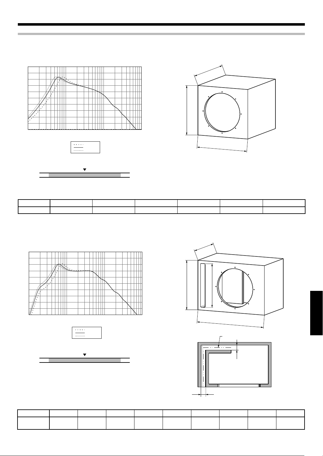
Casse raccomandateCasse raccomandate
A TENUTA
95
90
85
80
75
70
65
60
RESPONSE (dB)
55
50
45
10
5020 100 200 500 1K 2K 5K 10K
FREQUENCY (Hz)
0.8 [cu.ft]
1.25 [cu.ft]
1.75 [cu.ft]
D
H
W
Bassi ben de niti
Raccomandato
Bassi profondi
0,8 1,25 1,75
Volume [cu.ft]
Tipo Volume interno W H D
A TENUTA
1,25 cft (35,4 Litri) 375 mm (14-3/4") 370 mm (14-9/16") 355 mm (14") 282 mm (11-1/8") 0,11 cu.ft
Usare pannello di fibra a media densità (MDF) da 19 mm o pannello particellare ad alta densità.
CON PORTE
95
90
85
80
75
70
65
60
RESPONSE (dB)
55
50
45
10
5020 100 200 500 1K 2K 5K 10K
FREQUENCY (Hz)
1.0 [cu.ft]
1.5 [cu.ft]
2.0 [cu.ft]
* W, H, D: Dimensioni esterne
Foro di installazione Cubatura
D
H
SH
ITALIANO
W
SL
Bassi ben de niti
Raccomandato
Bassi profondi
1,0 1,5 2,0
Volume [cu.ft]
Tipo
CON PORTE
Volume interno
1,5 cft
(42,5 Litri)
WHD
507 mm
(19-15/16")
360 mm
(14-3/16")
320 mm
(12-5/8")
Foro di installazione
282 mm
(11-1/8")
Usare pannello di fibra a media densità (MDF) da 19 mm o pannello particellare ad alta densità.
SW
SW
SW SH SL
35 mm
(1-3/8")
322 mm
(12-11/16")
* W, H, D: Dimensioni esterne
Cubatura
480 mm
(18-7/8")
0,11 cu.ft
Italiano
7
Page 40

Funzionamento
Interruttore ILLUMINATION
Determina se l’illuminazione viene usata o meno.
Selettore MODE
Per quanto riguarda
le sue modalità,
consultare la tabella
che segue.
Manopola di cambio del colore
Usare questa manopola nella modalità "USER".
La coloritura può venire regolata a piacere.
Del tutto in senso antiorario = Bianco ←→ Rosso = del tutto in senso orario (sono
disponibili anche colori intermedi)
Cambio della modalità di illuminazioneCambio della modalità di illuminazione
Modalità On Music
La modalità On Music ha inizio automaticamente quando viene
rilevato del segnale musicale.
MODE 1 Modalità ciclica
Ripete le modalità MODE 2→MODE 3→USER→MODE 2...
Ciascuna modalità dura circa 20 secondi.
MODE 2 Modalità variabile
L’illuminazione ruota attorno a un cerchio.
Il colore dell’illuminazione cambia a seconda del
livello del segnale.
Livello basso del segnale = Blu scuro
Livello alto del segnale
È possibile regolare la sensibilità dell’illuminazione
con la manopola di controllo INPUT SENSITIVITY.
MODE 3 Modalità Sound Link
L’illuminazione cambia insieme alla musica.
Il colore dell’illuminazione cambia a seconda del
livello del segnale.
Livello basso del segnale = Bianco
ello alto del segnale
ITALIANO
USER Modalità User
È possibile regolare la sensibilità dell’illuminazione
con la manopola di controllo INPUT SENSITIVITY.
L’illuminazione cambia insieme alla musica.
È possibile cambiare il colore dell’illuminazione
con la manopola di cambio del colore. Bianco
Rosso (sono disponibili anche colori intermedi)
←→
←→
Rosso = Liv-
Rosso =
Note:
• Non si raccomanda l’uso dell’illuminazione a veicolo in moto.
• Non guardare a lungo l’illuminazione.
• La funzione di illuminazione può funzionare male se i
collegamenti sono scorretti. Non mancare di collegare l’unità
correttamente consultando la sezione "Collegamento" di questo
manuale (pagine 4 e 5).
Per scegliere la modalità di illuminazione, girare il
selettore MODE. Le modalità (MODE 1, 2, 3 o USER)
cambiano a seconda della presenza o assenza del
segnale.
Modalità Off Music
La mod alità Off Music vi ene impostata automaticamente se
nessun segnale viene ricevuto per 20 secondi.
MODE 1 Modalità ciclica
Ripete le modalità MODE 2→MODE 3→USER→MODE 2...
Ciascuna modalità cambia dop o esser stata suonata due
volte.
MODE 2 Modalità variabile
L’illuminazione scorre dall’alto verso il basso.
MODE 3 Modalità silenziosa
USER Modalità User
←→
Della luce bianca si accende lentamente.
Il colore scelto si accende lentamente.
È possibile cambiare il colore dell’illuminazione
con la manopola di cambio del colore. Bianco
Rosso (sono disponibili anche colori intermedi)
←→
Regolazione della sensibilità dell’illuminazioneRegolazione della sensibilità dell’illuminazione
Scatola di controllo
8
Italiano
1
Nella modalità "On Music" è possible regolare la
sensibilità dell’illuminazione.
Girare la manopola di controllo INPUT SENSITIVITÀ
usando un cacciavite per regolare la sensibilità di
illuminazione a piacere.
Page 41

Guida alla Soluzione di Problemi
Spesso, apparenti malfunzionamenti sono dovuti a un errore dell'utilizzatore.
Prima di richiedere riparazioni, consultare le seguenti tabelle.
Problema Causa Rimedio
• Un fusibile è saltato. • Controllare che le polarità (+) e (-) del cavo
• Ricollegare i cavi correttamente consultan-
• Il cavo di telecomando è scollegato. • Collegare il cavo al terminale REMOTE.
• Il piedino di alimentazione giallo del cavo
della c.c. non è collegato.
L’illuminazione non si accende.
L’illuminazione non è
sincronizzata con il suono.
Il colore dell’illuminazione
non cambia.
Nessun suono
Il suono è esile. • Il li vel lo in i ngresso è impostato tro ppo
La qualità sonora è cattiva
(il suono è distorto).
Il suono è innaturale.
• Il piedino di alimentazione blu/bianco del
cavo della c.c. non è collegato.
• Il cavo della c.c. non è ben collegato.
• Il piedino ner o di me ssa a terra del cavo
della c.c. non è collegato.
• Il cavo negativo (-) della batteria è scollegato.
• L’interruttore ON/OFF del telecomando si
trova su OFF.
• Il cavo Link cable non è collegato correttamente.
• Al diffusore non arriva segnale audio. • Collegare il cavo correttamente consultando
• Il volume del diffusore è basso. • Girare la manopola di controllo INPUT SEN-
• Il volume del diffusore è alto. • Girare la manopola di controllo INPUT SEN-
• Il selettore MODE si trova su "USER". • Portare il selettore MODE su MODE 1, 2 o 3 a
• L'attenuatore dell'unità centrale è stato portato su On.
• I cavi dei diffusori non sono collegati correttamente.
• I terminali di collegamento non sono collegati correttamente.
basso.
• Il livello in ingresso è impostato troppo alto.
• I cavi dei diffusori sono collegati alla polarità
(+) e (-) scorretta.
• Collegare il cavo correttamente consultando
• Controllare i collegamenti di tutti í cavi e
• Inserire a fondo il connettore.
• Applic are il cavo di me ssa a terra ad una
• Controllare i collegamenti di tutti í cavi e
• Portare l’interruttore ON/OFF su ON.
• Collegare il cavo correttamente consultando
• Inserire a fondo il connettore.
• Disattivare l'attenuatore.
• Collegare il cavo correttamente consultando
• Inserire i connettori o gli spinotti a fondo nei
• Regolare il volume dell’unità centrale.
• Collegare il cavo correttamente consultando
di alimentazione e degli altri cavi non siano
in corto circuito e se necessario sostituire il
fusibile installato con un altro del giusto amperaggio.
do in proposito l'esempio di collegamento a
pag 4, 5.
l'esempio a pag 4, 5.
quindi collegare il cavo (-) della batteria.
sezione metallica del veicolo, e non ad una
dipinta fissandolo fermamente con la vite.
quindi collegare il cavo (-) della batteria.
l'esempio a pag 4, 5.
l'esempio a pag 4, 5.
SITIVIT Y della scatola di controllo in senso
orario (lato MAX) a pag 8.
SITIVIT Y della scatola di controllo in senso
antiorario (lato MIN) a pag 8.
pag 8.
l'esempio a pag 4, 5.
terminali.
l'esempio a pag 4, 5.
ITALIANO
Caratteristiche tecniche
I seguenti valori nominali ed il design sono soggetti a modifiche senza preavviso.
[Unità altoparlante]
Subwoofer .... Cono di iniezione di polipropilene da 300 mm
Magnete da 740 g
Potenza di ingresso peak ................................................ 800 W
Potenza di ingresso massima ......................................... 400 W
Potenza di ingresso nominal .......................................... 200 W
Risposta in frequenza .............................................. 28 - 800 Hz
Sensibilità ........................................................90 dB / W ad 1 m
lmpedenza nominale ............................................................ 4 Ω
[Unità di controllo]
Tensión de funcionamiento .......................................................
14,4 V (margen de 10,5 ~ 16 V permitido)
Consumo corrente massimo ......................................... 150 mA
Capacità del fusibile ..............................................................2 A
Italiano
9
Page 42
INSTRUCCIONES DE SEGURIDAD IMPORTANTES
Precaución : Lea cuidadosamente estas páginas para asegurar una operación sin anomalías.
ADVERTENCIA ADVERTENCIA
• Antes de realizar el montaje o el cableado, etc., asegúrese de
retirar el cable del terminal negativo de la batería.
(De lo contrario pueden producirse cortocircuitos o incendios).
• Para impedir cortocircuitos, nunca ponga o deje objetos metálicos (tales como monedas o herramientas metálicas) en el
interior de la unidad.
• En el caso de que la unidad genere humo o un ruldo anormal,
desconecte inmediatamenta la slimentación. Después, consulte
con su conceslonario o centro de reparaciones más cercano tan
pronto como sea posible.
DESCONECTE LA ALIMENTACION!
• Conecta los altavocesequipados con lámpara de iluminación a
una bateria de 12 V CC con puesta a masa negativa.
• No trate de abrir ni modificar la unidad porque podría producirse un peligro de incendio o una avería.
• Después de sacer la unidad de la bolsa de polletileno, asegúrese
de poner la bolsa de polletileno donde no puedan alcanzarla
los niños. De otra forma, éstos podrfan jugar con la bolsa y se
podría producir un pellgro de asflxia.
PRECAUCIÓN PRECAUCIÓN
• La instalación y cableado del producto requiere la habilidad
y la experiencia de los expertos. Para garantizar la seguridad,
cerciórese de que sea su concesionario o un especialista quien
realice la instalación y el cableado.
• No instale el altavoz en un lugar expuesto a la luz solar directa o
a un calor o humedad excesivo.
• No instale los altavoces en lugares someticios al agua o a la humedad.
• No instale los altavoces en lugares inestabies ni en lugares
donde haya polvo.
•
Si saltara el fusible, después de comprobar si el cable ha sufrido un
cortocircuito, asegúrese de reemplazarlo por un fusible de la capacidad (amperaje) estipulada, tal como se indica en la caja de fusibles.
(El uso de fusibles de una capacidad que no sea la estipulada,
puede ser motivo de incendios).
¡Compruebe las indicaciones!
Para cambiar el fusible, remítase al manual de instrucciones del
vehículo.
• Para impedir un cortocircuito cuando sustituya un fusible,
desconecte primero el conjunto de los cables.
• No utilice gasolina, naftalina u otro tipo de disolvente para limpiar el altavoz. Limpielo pasando un panño blando y seco.
• Conecte sparadamente los cables de los altavoces a los conectores de altavoces apropiados. Compartir el cable negaivo del
altavoz o poner a masa los cables del altavoz en la carrocería del
automóvil puede ser la causa de que esta unidad no funcione
bien.
• Cuando haga un agujero debajo de un asiento, en el portamaletas o en cualquier otro punto del vehículo, compruebe que
no haya nada peligroso al otro lado como, por ejemplo, un
deposito de gasolina, tubería de frenos o conjuntos de cables, y
tenga cuidado para no dejar marcas y hacer otros daños.
• Para el montaje de tierra no sujete el cable a un airbag, la dirección o el sistema de frenado ni a ningún tornillo o tuerca críticos
ESPAÑOL
de la unidad de seguridad.
(Puede producir accidentes.)
• Durante el montaje, asegúrese de realizar el mismo en un sitio
que no interfiera con la conducción o que resulte peligroso para
los pasajeros al frenar bruscamente, etc.
(Causa de lesiones o accidentes).
• Después de instalar la unidad, asegúrese de que el equip o
eléctrico tal como luces de frenos, luces de intermitentes y limpiaparabrisas funcionen normalmente.
• El conduc tor deberá parar siempre el vehículo en un lugar
seguro antes de hacer lo siguiente.
– Utilizar el mando a distancia
• No utilice el producto con ningún otro propósito que no sea
montarlo a bordo.
Información acerca de la eliminación de equipos eléctricos y electrónicos al final de la vida
útil (aplicable a los países de la Unión Europea
que hayan adoptado sistemas independientes
de recogida de residuos)
Los productos con el símbolo de un contenedor con
ruedas tachado no podrán ser desechados como
residuos domésticos.
Los equipos eléctricos y electrónicos al final de la vida
útil, deberán ser reciclados en instalaciones que puedan dar el tratamiento adecuado a estos productos y a sus subproductos residuales correspondientes. Póngase en contacto con
su administración local para obtener información sobre el punto
de recogida más cercano. Un tratamiento correcto del reciclaje y
la eliminación de residuos ayuda a conservar los recursos y evita
al mismo tiempo efectos perjudiciales en la salud y el medio ambiente.
Declaración de conformidad
con respecto la Directiva EMC
2004/108/CE
Fabricante:
Kenwood Corporation
2967-3 Ishikawa-machi, Hachioji-shi, Tokyo,
192-8525 Japón
Representante en la UE:
Kenwood Electronics Europe BV
Amsterdamseweg 37, 1422 AC UITHOORN,
Países Bajos
2
Español
Page 43

Piezas incluidas
Nombre de
No.
Caja de control
1
Mando a
distancia
2
(Longitud del
cable: 6 m)
Cable de CC
(Longitud del
3
cable: 1,5 m)
Cable de enlace
(Longitud del
4
cable: 1 m)
pieza
Forma externa
Cantidad
KFC-W3000L
KFC-W3000LS
1–
1–
1–
118Almohadilla 11
No.
5
6
7
Nombre de
pieza
Casquillo de
cable
Tor nil lo
(ø 4 x 35)
Tor nil lo
(ø 4 x 16)
Forma externa
Cantidad
KFC-W3000L
KFC-W3000LS
11
88
2–
Español
ESPAÑOL
3
Page 44

Conexión
Precaución :
Antes de hacer el cableado, asegúrese de desconectar el cable conectado al terminal negativo de la batería. Después de terminar el cableado,
compruébelo de nuevo para asegurarse de que esté bien hecho. Después de terminar la comprobación, conecte el cable al terminal negativo
de la batería.
Unidad de graves
(KFC-W3000L)
Con este pr oducto no se incl uye un amplificador.
Utilic e un amplificador de venta en el come rcio
Cable del altavoz (vendido por separado)
Caja de control
1
especializado.
Cable de enlace
4
Cable de CC
3
Conecte co n la parte de bloqueo
del conec tor LINK hacia abajo.
Conecte el conector POWER de la caja de control
1
y el amplificador utilizando el cable de CC 3.
1
BATT: Amarillo
GND: Negro
P.CONT: Azul/Blanco
(Si el amplificador no tiene terminal de control de
la alimentación, conecte a la línea de accesorios
(ACC).)
Conecte el conector LINK de la caja de control 1
2
y el conector LINK IN de la unidad de graves utilizando el cable de enlace 4.
[No se puede utilizar un cable modular (de venta
en el comercio especializado).]
Conecte el amplificador y la unidad de graves con
3
los cables de altavoces.
Notas:
•
La función de iluminación no se puede utilizar si el cable de enlace
4
Asegúrese de conectar el cable de enlace 4 al conector LINK IN.
• No enchufe ni desenchufe los cables de conexión sin haber
desconectado la alimentación. De lo contrario podría producirse un
fallo en el funcionamiento.
Conexión de la unidad de mando a distanciaConexión de la unidad de mando a distancia
Caja de control
1
Fusible (2A)
Batería
está mal conectado al conector LINK OUT de la unidad de graves.
Amplificador
Si no hubiera
ningún terminal
de control de
alimentación en
el amplificador,
conecte los cables
azul y blanco a
la línea accesoria
(línea de posición
ACC de la llave de
contacto).
Unidad central
Conecte el mando a distancia 2 al terminal REMOTE
de la caja de control 1.
ESPAÑOL
Mando a distancia
2
Nota:
La función de iluminación no se puede utilizar cuando el mando a distancia 2 no está conectado. Asegúrese de conectar el mando a distancia
a la caja de control 1.
2
Español
4
Page 45

Conexión de la KFC-W3000L y la KFC-W3000LS (usuarios de la KFC-W3000LS solamente)
Unidad de graves
(KFC-W3000LS)
Unidad de graves
Unidad de graves
Conecte el conector LINK OUT de la unidad de
1
3
4
2
graves 1 (KFC-W3000L) y el conector LINK IN de
la unidad de graves 2 (KFC-W3000LS) utilizando
el cable de enlace 4.
Conecte el amplificador y la unidad de graves con
2
los cables de altavoces.
Cable de enlace
4
Notas:
• La función de iluminación de la KFC-W3000LS solo se activa cuando
La función de iluminación no se puede utilizar cuando la KFC-
• El máximo número de unidades KFC-W3000LS conectadas es 3
• La función de iluminación no se puede utilizar si el cable de en-
• La iluminación se sincroniza con la entrada de señal de música
La iluminación de las unidades de graves conectadas 2, 3 y 4
• No enchufe ni desenchufe los cables de conexión sin haber
Unidad de graves
(KFC-W3000L)
ésta está conectado a la KFC-W3000L mediante el cable de enlace
.
4
W3000LS no está conectada a la KFC-W3000L.
(el número máximo de unidades de graves incluyendo la KFCW3000L es 4).
lace 4 está mal conectado al conector LINK OUT de la unidad
de graves 2 (KFC-W3000LS). Asegúrese de conectar el cable de
enlace 4 al conector LINK IN.
en el terminal de altavoz de la unidad de graves 1 (KFC-W3000L).
(KFC-W3000LS) se encienden según la unidad de graves 1 (KFCW3000L). Tenga en cuenta que no se sincronizan con las señales
introducidas en ellas.
desconectado la alimentación. De lo contrario podría producirse
un fallo en el funcionamiento.
1
AmplificadorAmplificador
Caja de
1
control
Cambio de fusibles
Realice el cambio con fusibles de la capacidad especificada.
Precaución : Asegúrese de realizar el cambio con fusibles de la misma capacidad (amperaje) tal como se indica en el
fusible. Este producto es de 2A.
Extracción Inserción
Fusibl e
Abra la cubierta.
1
Tómelo con unos alicates y tire hacia arriba.
2
Cubier ta
Soporte de fusibles
Fusible de recambio 2A
Introduzca suavemente el fusible en el portafusible y
1
empújelo hasta el fondo con su dedo o con una herramienta.
Cierre la cubierta.
2
Español
ESPAÑOL
5
Page 46

Instalación
Fijación el SubwooferFijación el Subwoofer
Ponga la plantilla suministrada en el panel y
1
luego marque las posiciones de los agujeros.
Haga un agujero grande y agujeros para los tor-
2
nillos.
Desprenda la cubierta del espaciador y coloque
3
el espaciador en la parte posterior de la brida del
altavoz para que la brida quede cubierta completamente.
Tornillo (ø 4 x 35) x 8
6
Cómo utilizar el casquillo del cableCómo utilizar el casquillo del cable
Cuando utilice una caja para graves, emplee el casquillo de
cable suministrado.
En la caja de graves, haga un agujero (ø 17,5) para
1
colocar el casquillo de cable 5.
Pase el cable de enlace 4 a través del agujero de
2
la caja de graves.
Coloque el casquillo de cable 5 en una posición
3
apropiada del cable de enlace 4.
Empuje el casquillo de cable 5 hacia el interior
4
del agujero de la caja de graves.
Cable de enlace
4
ø 17,5
Casquillo de cable
5
Notas:
• Fije firmemente el casquillo de cable 5 porque la holgura
permitirá la entrada de aire.
• Tenga cuidado de no pellizcar el cable de enlace 4 con la superficie del casquillo de cable 5.
Fijación de la caja de controlFijación de la caja de control
Tornillo (ø 4 x 16) x 2
7
POWERREMOTE LINK
ESPAÑOL
Especificaciones técnicasEspecificaciones técnicas
SÍMBOLO UNIDAD VALOR
Impedancia nominal
Resistencia de CC
Inductancia de bobina móvil
Área de pistón
Factor de fuerza
Docilidad acústica
Masa móvil
Frecuencia de resonancia
Factor Q mecánico
Factor Q eléctrico
Factor Q total
Potencia de pico
Amplitud de pico
Desplazamiento
Profundidad de montaje
Peso del imán
Diámetro de la bobina móvil
ZΩ4
Revc Ω 3,4
Levc mH 0,56
Sd sq.m 0,052
BL T.m 9,53
Vas
Mms g 105,6
Fs Hz 30,9
Qms 9,59
Qes 0,77
Qts 0,71
Xmax mm 4,6
Liters 97,75
cu.ft 3,45
W 800
cc 5.190
cu.ft 0,183
mm (in.) 150 (5-7/8)
g (oz) 740 (26,1)
mm (in.) 50 (1-15/16)
6
Español
Page 47

Cajas recomendadasCajas recomendadas
SELLADAS
95
90
85
80
75
70
65
60
RESPONSE (dB)
55
50
45
10
5020 100 200 500 1K 2K 5K 10K
FREQUENCY (Hz)
0.8 [cu.ft]
1.25 [cu.ft]
1.75 [cu.ft]
D
H
W
Graves herméticos
Recomendado
Graves profundos
0,8 1,25 1,75
Volumen [cu.ft]
Tipo Volumen interior W H D
SELLADAS
1,25 cft (35,4 Litros) 375 mm (14-3/4") 370 mm (14-9/16") 355 mm (14") 282 mm (11-1/8") 0,11 cu.ft
Agujero de montaje Desplazamiento
Utilice un tablero de partículas de densidad alta o un tablero de fibra de densidad media (MDF) de 19 mm (3/4 de pulgada) de grosor.
ABIERTO
95
90
85
80
75
70
65
60
RESPONSE (dB)
55
50
45
10
5020 100 200 500 1K 2K 5K 10K
FREQUENCY (Hz)
1.0 [cu.ft]
1.5 [cu.ft]
2.0 [cu.ft]
D
H
SH
W
SL
* W, H, D : Dimensiones externas
Graves herméticos
Recomendado
Graves profundos
SW
1,0 1,5 2,0
Volumen [cu.ft]
SW
Tipo
ABIERTO
Volumen interior
1,5 cft
(42,5 Litros)
WHD
507 mm
(19-15/16")
360 mm
(14-3/16")
320 mm
(12-5/8")
Agujero de montaje
282 mm
(11-1/8")
SW SH SL
35 mm
(1-3/8")
322 mm
(12-11/16")
Utilice un tablero de partículas de densidad alta o un tablero de fibra de densidad media (MDF) de 19 mm (3/4 de pulgada) de grosor.
* W, H, D : Dimensiones externas
Desplazamiento
480 mm
(18-7/8")
0,11 cu.ft
Español
ESPAÑOL
7
Page 48

Operation
Conmutador ILLUMINATION
Selecciona si se utiliza la iluminación o no.
Selector MODE
Consulte la tabla
descrita más abajo para
cada modo.
Control de cambio de color
Utilice este control en el modo "USER".
El tono del color se puede cambiar como se desee.
Girado completamente hacia la izquierda = Blanco ←→ Rojo = Girado completamente
hacia la derecha (Se encuentran disponibles colores intermedios)
Cambio del modo de iluminaciónCambio del modo de iluminación
Modo de música encendida
Se entra en el modo de música encendida cuando se detecta una
señal de música.
MODE 1 Modo de cambio
Repite los modos MODE 2→MODE 3→USER→MODE 2...
Cada modo cambia cada 20 segundos.
MODE 2 Modo variable
La iluminación gira en forma de circunferencia.
Los cambios del color de la iluminación dependen
del nivel de la señal.
Nivel de señal bajo = Azul profundo
Señal de nivel alto
Con el control INPUT SENSITIVITY puede ajustar la
sensibilidad de la iluminación.
MODE 3 Modo de enlace de sonido
La iluminación se enciende en sincronismo con la música.
Los cambios del color de la iluminación dependen
del nivel de la señal.
Nivel de señal bajo = Blanco ←→ Rojo = Nivel de
señal alto
Con el control INPUT SENSITIVITY puede ajustar la
sensibilidad de la iluminación.
USER Modo del usuario
La iluminación se enciende en sincronismo con la música.
Pue de cambiar el color de la iluminación con el
control de cambio de color. Blanco ←→ Rojo (Se
encuentran disponibles colores intermedios)
←→
Rojo =
Notas:
• No se recomienda emplear la iluminación cuando el vehículo
está en movimiento.
• No m ire fijame nte la luz de ilum inación du rante un largo
periodo de tiempo.
• La función de iluminación puede fallar si las conexiones están
mal hechas. Asegúrese de conectar correctamente el equipo
consultando "Conexión" en este manual (en las páginas 4, 5).
Gire el selector MODE para seleccionar el modo
de iluminación. Cada modo (MODE 1, 2, 3 o USER)
cambia dependiendo de si existe señal de música o
no.
Modo de música apagada
Se entra en el modo de música apagada cuando no se introduce
señal de música durante 20 segundos.
MODE 1 Modo de cambio
Repite los modos MODE 2→MODE 3→USER→MODE 2...
Cada modo cambia después de reproducirse dos veces.
MODE 2 Modo variable
La iluminación se desplaza de arriba hacia abajo.
MODE 3 Modo de silencio
USER Modo del usuario
El blanco se enciende lentamente.
El color seleccionado se enciende lentamente.
Puede cam biar el color de iluminaci ón con el
control de cambio de color. Blanco
encuentran disponibles colores intermedios)
←→
Rojo (Se
Ajuste de la sensibilidad de iluminaciónAjuste de la sensibilidad de iluminación
ESPAÑOL
Caja de control
1
Español
8
En el modo "Modo de música encendida" puede
ajustar la sensibilidad de la iluminación.
Gire el control INPUT SENSITIVITY con un destornillador de punta plana para ajustar la sensibilidad
de la iluminación como usted quiera.
Page 49

Guía para la solución de averías
A menudo, lo que parece una avería se debe a un error del usuario. Antes de llamar al servicio de reparaciones, consulte la tabla siguiente.
Problema Causa Solución
La iluminación no se enciende.
La iluminación no se
sincroniza con el sonido.
El color de la iluminación no
cambia.
• El fusible està fundido. • Compruebe que la polaridad (+)/(-) del cable
• El cable del mando a distancia está desenchufado.
• El contacto de alimentación (amarillo) del
cable de CC no está conectado.
• El contacto de control de alimentación (azul/
blanco) del cable de CC no está conectado.
• El cable de CC no está completamente enchufado.
• El contacto de masa (negro) del cable de CC
no está conectado.
• El cable negativo (-) de la bate ría del automóvil está desconectado.
• El interruptor ON/OFF del mando a distancia
está en OFF.
• El cable de enlace está mal conectado. • Conecte correctamente el cable consultan-
• No se introduce señal de audio al altavoz. • Conecte correctamente el cable consultan-
• El volumen del altavoz está bajo. • Ajuste con el control INPUT SENSITIVITY de
• El volumen del altavoz está alto. • Ajuste con el control INPUT SENSITIVITY de
• El selector MODE se pone en "USER". • Ponga el selector MODE en MODE 1, 2 ó 3 (en
• El atenuador de la unidad central está en ON. • Desconecte el atenuador.
de alimentación no esté cortocircuitada, y luego ponga un fusible del amperaje nominal.
• Vuelva a conectar correctamente los cables
consultando el ejemplo de conexión (en la
página 4, 5).
• Enchufe el cable en el terminal REMOTE.
• Conecte correctamente el cable consultando el ejemplo de conexión (en la página 4, 5).
• Compruebe las conexiones de todos los cables y luego conecte el cable (-) a la batería.
• Introduzca a fondo el conector.
• Coloque el terminal de masa en la sección
metálica del vehículo (superficie sin cubrir)
apretándolo firmemente.
• Compruebe las conexiones de todos los cables y luego conecte el cable (-) a la batería.
• Ponga el interruptor ON/OFF en ON.
do el ejemplo de conexión (en la página 4, 5).
• Introduzca a fondo el conector.
do el ejemplo de conexión (en la página 4, 5).
la caja de control girándolo hacia la derecha.
(Lado MAX) (en la página 8).
la caja de control girándolo hacia la izquierda. (Lado MIN) (en la página 8).
la página 8).
No hay sonido
El sonido es bajo. • El nivel de entrada está ajustado demasiado
La calidad del sonido esbaja
(el sonido es distorsionado).
El sonido no es natural.
• Los cables del altavoz no están conectados
correctamente.
• Los terminales de conexión están mal conectados.
bajo.
• El nivel de entrada está ajustado demasiado
alto.
• Los cables del altavoz están conectados con
sus p olaridades positiva (+) y negativa (-)
cambiadas.
Especificaciones
Los valores nominales y el diseño siguientes están sujetos a cambios sin previo aviso.
[Unidad de altavoz]
Subwoofer ...
Magnetico de 740 g
Potencia de entrada cúspide .......................................... 800 W
Potencia de entrada máxima .......................................... 400 W
Potencia de entrada nominal ......................................... 200 W
Respuesta de frecuencia ......................................... 28 - 800 Hz
Cono de inyección de polipropileno de 300 mm
Sensibilidad .......................................................90 dB / W a 1 m
Impedancia nominal ............................................................. 4 Ω
[Unidad de control]
Tensión de funcionamiento .......................................................
14,4 V (margen de 10,5 ~ 16 V permitido)
Consumo máximo de corriente .................................... 150 mA
Capacidad de fusible .............................................................2 A
• Conecte correctamente el cable consultando el ejemplo de conexión (en la página 4, 5).
• Inserte a fondo los conectores o las tomas
en los terminales.
• Ajuste el volumen de la unidad central.
• Conecte correctamente el cable consultando el ejemplo de conexión (en la página 4, 5).
Español
ESPAÑOL
9
Page 50

ВАЖНЫЕ ИНСТРУКЦИИ ПО БЕЗОПАСНОСТИ
Внимание: Для обеспечения безопасной работы, внимательно изучите данную страницу.
ПРЕДУПРЕЖДЕНИЕПРЕДУПРЕЖДЕНИЕ
• Перед монтажом или соединением проводов, др., обязательно удалите провод от минусового терминала батарейки.
(В противном случае, это может привести к короткому замыканию или пожару.)
• Во избежание короткого замыкания, никогда не кладите или
оставляйте любые металлические предметы (например, монеты или металлические инструменты) внутри блок.
• В случае образования дыма или неестественного запаха от
данного аппарата, немедленно переключите питание на OFF.
После этого, пожалуйста, по возможности быстро свяжитесь
с дилером или ближайшей станцией техобслуживания.
ОТКЛЮЧИТЕ ПИТАНИЕ!
• Подключите колонки с подсвечивающими лампами к источнику 12В постоянного тока, с заземлением отрицательного
полюса.
• Не пытайтесь открыть или модифицировать аппарат, так как
это может привести к пожару или поломке.
• После извлечения аппарата из полиэтиленового пакета,
обязательно выкиньте полиэтиленовый пакет, во избежание
попадания в руки детей. В ином случае, они могут начать играть с пакетом, что может привести к удушью.
ВниманиеВнимание
• Установка и соединение проводов изделия требует специальных знаний и опыта. Для обеспечения безопасности, установка и соединения должны производиться дилером или
специалистом.
• Не устанавливайте колонку в местах, подвергающихся прямому попаданию солнечных лучей или излишнему нагреванию или влажности.
• Не устанавливайте колонки в местах, где они могут подвергнуться попаданию воды или влаги.
• Не устанавливайте колонки в неустойчивых местах, или местах, где легко образуется пыль.
• При сгорании пре дохранителя, после проверки того, не
подвергнулся ли кабель короткому замыканию, обязательно
замените на предохранитель указанного размера (амперной
нагрузки), как показано в блоке предохранителей.
(Использование предохранителей, кроме предохранителей
указанного размера, может привести к пожару.)
Проверьте дисплей!
Для замены предохранителя, смотрите инструкцию по экслу-
атации к автомобилю.
• Во избежание короткого замыкания при замене предохранителя, сначала отсоедините жгут проводов.
• При чистке колонки, не используйте бензин, керосин, или
любой тип растворителя. При очистке, протирайте мягкой,
сухой тканью.
• Подключайте провода колонок к соответствующим разъемам
колонок по-отдельности. Общее использование отрицательного провода колонки или заземление проводов колонки на
металлический корпус машины может привести к поломке
данного аппарата.
• При создании отверстия под сиденьем, внутри багажника,
или еще где-либо на автомобиле, проверьте, нет-ли ничего
опасного на противоположной стороне, как бензобак, тормозной шланг, или жгут проводов, и будьте внимательны во
избежание царапин или других повреждений.
• Для монтажа провода заземления, не прикрепляйте провод
к подушке безопасности, системе рулевого управления или
тормозной магистрали или другим важным болтам или гайкам устройства безопасности.
(Может привести к авариям.)
РУССКИЙ
• При монтаже, обязательно устанавливайте в местах, не мешающих вождению, или где могут быть опасны для пассажиров
во время экстренного торможения, др.
(Причина травм или аварий.)
• После установки данного аппарата, убедитесь, что электрооборудование, например, тормозные лампы, поворотные
сигналы и дворники работают как обычно.
• Перед выполнением следующего действия, водитель обязан
всегда сначала остановить автомобиль в безопасном месте.
– Управление пультом ДУ
• Изделие должно использоваться только на автомобиле и не
должно использоваться в других целях.
При Правильнoм coблюдснии всех уcлoвий эксплуатации и
техническких требований, указанных в даннoй инструкций,
сpoк службы купленного Вaм изделия составляет 7 лет.
Гарантийный срок эксплуатации изделия соoтветствует
сpoку, указанному в гарантийнoм талоне.В период сpoка
службы эксплуатация и хранение изделия не может представлять опасность для Вaшей жизни, здоровья, причинять
вред Вaшему имуществу или oкружающей среде.
Изделие изгoтовленo в Китае.
2
Русский
Page 51
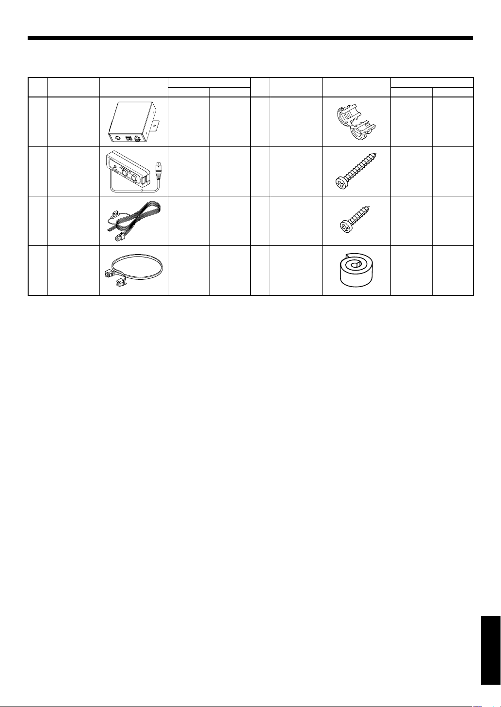
Поставляющиеся детали
Название
No.
Блок
1
управления
Пульт ДУ
(Длина
2
провода: 6 м)
Кабель
постоянного
тока
3
(Длина кабеля:
Соединительный
кабель
4
(Длина кабеля:
детали
1,5 м)
1 м)
Внешняя форма
Количество
KFC-W3000L
KFC-W3000LS
1–
1–
1–
118Подкладка 11
No.
5
6
7
Название
детали
Втулка
провода
Винт
(ø 4 x 35)
Винт
(ø 4 x 16)
Внешняя форма
Количество
KFC-W3000L
KFC-W3000LS
11
88
2–
Русский
РУССКИЙ
3
Page 52

Подключение
Внимание:
Перед соединением, обязательно удалите провод с отрицательного терминала батарейки. После завершения всех соединений, снова
убедитесь в правильности соединений. После проверки, подключите провод от отрицательного терминала батарейки.
Низкочастотный динамик
(KFC-W3000L)
Усилите ль к данному из делию не прилагаетс я.
Пожалуйста , используйте усилит ель,
Провод колонки (продается отдельно)
Блок управления
1
Соединительный
4
кабель
Подключите к фиксирующей
части в нижней части гнезда LINK.
Подключите гнездо POWER Блока управления 1
1
и усилитель через кабель постоянного тока 3.
(Если на усилителе не имеется терминала
управления питанием, подключите к линии
дополнительного оборудования (АСС).)
Подключите гнездо LINK Блока управления 1
2
и гнездо LINK IN Низкочастотного динамика
через Соединительный кабель 4.
(Модульный кабель (продающийся отдельно)
не может использоваться.)
Подключите усилитель и Низкочастотный
3
динамик через провода колонок.
Подключение пульта ДУПодключение пульта ДУ
Блок управления
1
Кабель
3
постоянного тока
BATT: Желтый
GND: Черный
P.CONT: Синий/Белый
Примечания:
• Функция подсветки не может использоваться, если
Соединительный кабель 4 ошибочно подключен к гнезду LINK
OUT на Низкочастотном динамике. Соединительный кабель 4
должен подключаться к гнезду LINK IN.
• Не подключайте или отсоединяйте соединительные кабели без
предварительного отключения питания. В противном случае,
это может привести к сбоям.
прода ющийся отдел ьно.
Предохранитель
Аккумулятор
Усил ител ь
(2A)
Если на усилителе не
имеется терминала
управления питанием,
подключите синий/
белый провод к линии
дополнительного
оборудования (линия
на позиции АСС
переключателя замка
зажигания).
Центральный блок
Подключите Пульт ДУ 2 к терминалу REMOTE
Блока управления 1.
Пульт ДУ
2
Примечание:
Функция подсветки не может использоваться, если Пульт ДУ 2 не подключен. Обязательно подключите Пульт ДУ 2 к Блоку управления 1.
РУССКИЙ
Русский
4
Page 53

Подключение KFC-W3000L и KFC-W3000LS (только для пользователя KFC-W3000LS)
Низкочастотный динамик
(KFC-W3000LS)
Низкочастотный
динамик
3
Низкочастотный
динамик
4
Подключите гнездо LINK OUT Низкочастотного
1
2
динамика 1 (KFC-W3000L) и гнездо LINK IN
Низкочастотного динамика 2 (KFC-W3000LS)
через Соединительный кабель 4.
Подключите усилитель и Низкочастотный
2
динамик через провода колонок.
Низкочастотный динамик
(KFC-W3000L)
Соединительный кабель
4
Примечания:
• Функция подсветки KFC-W3000LS срабатывает только при его
подключении к KFC-W3000L через Соединительный кабель 4.
Функция подсветки не может использоваться, если KFC-
W3000LS не подключен к KFC-W3000L.
• Максимальное количество подключаемых изделий KFCW3000LS - 3 (максимальное общее количество Низкочастотных
динамиков, включая KFC-W3000L - 4).
• Функция подсветки не может использоваться, если
Соединительный кабель 4 ошибочно подключен к гнезду
LINK OUT Низкочастотного динамика 2 (KFC-W3000LS).
Соединительный кабель 4 должен подключаться к гнезду LINK
IN.
• Подсветка синхронизируется с музыкальным сигналом,
поступающим на терминал колонки Низкочастотного динамика
(KFC-W3000L).
1
Подсветки подключенных Низкочастотных динамиков
2, 3, 4
Низкочастотным динамиком 1 (KFC-W3000L). Помните, что они
не синхронизируются с поступающими на них сигналами.
• Не подключайте или отсоединяйте соединительные кабели без
предварительного отключения питания. В противном случае,
это может привести к сбоям.
1
Усил ител ьУсили тель
Блок
1
управления
(KFC-W3000LS) высвечиваются в соответствии с
Замена предохранителя
Заменяйте на предохранитель указанной мощности.
Внимание: Обязательно замените на предохранитель с одинаковой мощностью (амперной нагрузкой) как отображено на
предохранителе. Нагрузка данного изделия - 2A.
Извлечение Установка
Предохранитель
Патрон предохранителя
Откройте крышку.
1
Захватите плоскогубцами и вытяните.
2
Крышка
Замена предохранителя на 2А
Осторожно вставьте предохранитель в гнездо
1
предохранителя и надавите пальцем или
инструментом до полной установки
Закройте крышку.
2
РУССКИЙ
.
Русский
5
Page 54

Установка
Закрепление сабвуфераЗакрепление сабвуфера
Разместите прилагаемый шаблон на панели, а
1
затем отметьте положения отверстий.
Откройте большое отверстие и сделайте
2
отверстия под винты.
Снимите защитный лист с прокладки и
3
прикрепите ее к кромке на задней стороне
громкоговорителя так, чтобы кромка была
полностью закрыта.
Винт (ø 4 x 35) x 8
6
Как использовать Втулку проводаКак использовать Втулку провода
При использовании корпуса для Низкочастотного динамика,
используйте прилагаемую Втулку провода.
На корпусе Низкочастотного динамика, проделайте
1
отверстие (ø 17,5) для установки Втулки провода 5.
Пропустите Соединительный кабель 4 через
2
отверстие корпуса Низкочастотного динамика.
Закрепите Втулку провода 5 на соответствующей
3
позиции Соединительного кабеля 4.
Протолкните Втулку провода 5 в отверстие на
4
корпусе Низкочастотного динамика.
Соединительный
4
кабель
ø 17,5
Втулка провода
5
Примечания:
• Надежно вставьте Втулку провода 5, так как при наличии
зазоров, будет происходить протекание воздуха.
• Соблюдайте предосторожность, чтобы не допустить
сдавливания Соединительного кабеля 4 на поверхности
Втулки провода 5.
Установка Блока управленияУстановка Блока управления
Винт (ø 4 x 16) x 2
7
POWERREMOTE LINK
РУССКИЙ
Технические характеристикиТехнические характеристики
Номинальный импеданс
Сопротивление
постоянному току
Индукция звуковой
катушки
Площадь поршня
Коэф. электромех. связи
Акустическая податливость
уровня громкости
Масса перемещения
Частота резонанса
Механический фактор
качества
Электрический фактор
качества
Общий фактор качества
Пиковая мощность
Пиковая амплитуда
Смещение
Монтажная глубина
Вес магнита
Диаметр звуковой катушки
ОБОЗНАЧЕНИЕ
ZΩ4
Revc Ω 3,4
Levc mH 0,56
Sd sq.m 0,052
BL T.m 9,53
Vas
Mms g 105,6
Fs Hz 30,9
Qms 9,59
Qes 0,77
Qts 0,71
Xmax mm 4,6
ЕДИНИЦА ЗНАЧЕНИЕ
Liters 97,75
cu.ft 3,45
W 800
cc 5.190
cu.ft 0,183
mm (in.) 150 (5-7/8)
g (oz) 740 (26,1)
mm (in.) 50 (1-15/16)
6
Русский
Page 55

Рекомендуемые оболочкиРекомендуемые оболочки
ГЕРМЕТИЧЕСКИ ЗАКРЫТЫЙ
95
90
85
80
75
70
65
60
RESPONSE (dB)
55
50
45
10
5020 100 200 500 1K 2K 5K 10K
FREQUENCY (Hz)
0.8 [cu.ft]
1.25 [cu.ft]
1.75 [cu.ft]
D
H
W
тугой бас
Рекомендуется
глубокий бас
0,8 1,25 1,75
уровень громкости [cu.ft]
* W, H, D: Внешние габариты
Тип
ГЕРМЕТИЧЕСКИ ЗАКРЫТЫЙ
Внутренний уровень громкости
WHD
Монтажное отверстие
Смещение
1,25 cft (35,4 Литра) 375 mm (14-3/4") 370 mm (14-9/16") 355 mm (14") 282 mm (11-1/8") 0,11 cu.ft
Используйте древесноволокнистую плиту средней плотности (MDF) или древесностружечную плиту высокой плотности толщиной 19 мм (3/4 дюйма).
С ОТВЕРСТИЯМИ
95
90
85
80
75
70
65
60
RESPONSE (dB)
55
50
45
10
5020 100 200 500 1K 2K 5K 10K
FREQUENCY (Hz)
1.0 [cu.ft]
1.5 [cu.ft]
2.0 [cu.ft]
D
H
SH
W
SL
тугой бас
Рекомендуется
глубокий бас
SW
1,0 1,5 2,0
уровень громкости [cu.ft]
SW
* W, H, D: Внешние габариты
Тип
С ОТВЕРСТИЯМИ
Внутренний уровень громкости
1,5 cft
(42,5 Литра)
WHD
507 mm
(19-15/16")
360 mm
(14-3/16")
320 mm
(12-5/8")
Монтажное отверстие
282 mm
(11-1/8")
SW SH SL
35 mm
(1-3/8")
322 mm
(12-11/16")
480 mm
(18-7/8")
Смещение
0,11 cu.ft
Используйте древесноволокнистую плиту средней плотности (MDF) или древесностружечную плиту высокой плотности толщиной 19 мм (3/4 дюйма).
Русский
РУССКИЙ
7
Page 56

Управление
Переключатель ILLUMINATION
Выберите, используется-ли подсветка или нет.
Селект ор MODE
По каждому режиму,
смотрите таблицу,
приведенную ниже.
Уровень переключения цвета
Данная ручка используется в режиме "USER".
Оттенок цвета можно отрегулировать по желанию.
Полностью против часовой стрелки = Белый ←→ Красный = Полностью по
часовой стрелке ( доступны промежу точные цвета)
Переключение режима подсветкиПереключение режима подсветки
Режим On Music Mode
Режим On Music M ode вк люч ается пр и обн ару жен ии
музыкального сигнала.
MODE 1 Циклический режим
Повторяет MODE 2→MODE 3→USER→MODE 2...
Каждый режим переключается каждые 20 секунд.
MODE 2 Переменный режим
Подсветка переключается по кругу.
Переключение цвета подсветки зависит уровня
сигнала.
Низкий уровень сигнала = Темно-синий
Красный = Высокий уровень сигнала
Чувствительность подсветки можно отрегулировать
с помощью ручки управления INPUT SENSITIVITY.
MODE 3 Режим Sound Link
Подсветка высвечивается в синхронизации с музыкой.
Перек лючение цв ета подсветки з ависи т уровня
сигнала.
Низкий уров ень сиг нала = Бе лый ←→ Крас ный =
Высокий уровень сигнала
Чувствительность подсветки можно отрегулировать с
помощью ручки управления INPUT SENSITIVITY.
USER Режим пользователя
Подсветка высвечиваетс я в синхр онизации с
музыкой.
Цвет подсветки можно переключать с помощью
регулировки Color change. Белый ←→ Красный
(доступны промежуточные цвета)
←→
Примечания:
• Не рекомендуется включать подсветки во время движения
автомобиля.
• Не смотрите на подсветку продолжительное время.
• При ошибочных подключениях, функция подсветки может
срабатывать неправильно. Оборудование должно быть
подключено соответствующим образом, согласно указаниям
в "Подключение" в данном руководстве (на стр. 4, 5).
Поворачивайте ручку селектора MODE для
выбора режима подсветки. Каждый режим
(MODE 1, 2, 3 или USER) переключается в
зависимости от наличия или отсутствия
музыкального сигнала.
Режим Off Music Mode
Режим Off Music Mode включается, если в течение 20 секунд
не поступает музыкальный сигнал.
MODE 1 Циклический режим
Повторяет MODE 2→MODE 3→USER→MODE 2...
Каждый режим переключается после двойного
воспроизведения.
MODE 2 Переменный режим
Подсветка протекает сверху вниз.
MODE 3 Тихий режим
USER Режим пользователя
Медленно высвечивается белая подсветка.
Медленно высвечивается выбранный цвет.
Цвет подсветки можно переключать с помощью
регулировки Color change. Белый
(доступны промежуточные цвета)
←→
Красный
Регулировка чувствительности подсветкиРегулировка чувствительности подсветки
Блок управления
РУССКИЙ
Русский
8
1
В режиме "On Music Mode", можно
отрегулировать чувствительность подсветки.
Используя минусовую отвертку, поворачивайте
ручку управления INPUT SENSITIVITY и
отрегулируйте нужную чувствительность
подсветки.
Page 57

Руководство по возможным неисправностям и способам их устранения
Часто ошибка в использовании принимается за неисправность. Перед обращением в мастерскую, пожалуйста, изучите следующую таблицу.
Неисправность Причина Способ устранения
• Обгорел предохранитель.
• Не подключен кабель пульта ДУ. • Подключите кабель в терминал REMOTE.
• Не подключен контакт (желтый) энергообеспечения на 4-контактном соединительном кабеле.
• Не подключен контакт (синий/белый)
управления питанием на 4-контактном
Подсветка не высвечивается.
Подсветка не синхронизируется со звучанием.
Не переключается цвет подсветки.
Отсутствует звук
Малый уровень громкости. • Установлен низкий уровень входа.
Плохое качество звучания
(звучание искажено).
Неестественное звучание.
соединительном кабеле.
• Неполностью подключен 4-контактный соединитель.
• Не подключен контакт (черный) заземления на 4-контактном соединительном
кабеле.
• Отсоединен отрицательный (-) кабель
аккумулятора автомобиля.
• Переключатель ON/OFF на пульте ДУ установлен на OFF.
• TНеправильно подключен Соединительный кабель.
• На колонку не поступает аудиосигнал. •
• Слишком низкий уровень громкости колонки.
• Слишком высокий уровень громкости колонки.
• Селектор MODE установлен на "USER". • Поверните селектор MODE на MODE 1, 2,
Аттенюатор центрального блока установлен на ON.
•
• Ненадежно подключены кабели колонок. • Правильно подключите кабели, используя
• Ненадежно подключены терминалы подключения.
• Установлен высокий уровень входа.
• Кабели колонок подключены с неправильной положительной(+)/отрицательной (-) полярностью.
• Проверьте полярность (+)/(-) силового кабеля, а также, что кабели не замкнуты коротко, затем замените
на предохранитель с установленной мощностью.
• Заново подключите кабели соответствующим образом, используя пример подключения (на стр. 4, 5).
• Подключите кабель соответствующим
образом, используя пример подключения
(на стр. 4, 5).
• Проверьте подключения всех кабелей, затем подключите кабель (-) к аккумулятору.
• Полностью вставьте соединитель.
• Закрепите терминал заземления на металлической части автомобиля (неокрашенной
поверхности) и надежно прикрутите его.
• Проверьте подключения всех кабелей, затем подключите кабель (-) к аккумулятору.
• Установите переключатель ON/OFF на ON.
•
Подключите кабель соответствующим образом, используя пример подключения (на
стр. 4, 5).
•
Полностью вставьте соединитель.
Подключите кабель соответствующим образом, используя пример подключения (на
стр. 4, 5).
• Поворачивайте ручку управления INPUT
SENSITIVITY на Блоке управления по часовой стрелке (в сторону MAX) (на стр. 8).
• Поворачивайте ручку управления INPUT
SENSITIVITY на Блоке управления против
часовой стрелки (в сторону MIN) (на стр. 8).
или 3 (на стр. 8).
• Переключите аттенюатор на OFF.
пример подключения (на стр. 4, 5).
• Полностью вставьте соединители или
гнезда в терминалы.
• Отрегулируйте уровень громкости Центрального блока.
• Правильно подключите кабели, используя
пример подключения (на стр. 4, 5).
Технические характеристики
Следующие данные и дизайн могут изменяться без уведомления.
[Колонка]
Низкочастотный громкоговоритель
...
Вводной полипропиленовый конус - 300 мм (12 дюймов)
Магнит - 740 г (26, 1 унций)
Пиковая входная мощность ........................................800 Вт
Максимальная входная мощность ............................400 Вт
Среднеквадратическая входная мощность .............200 Вт
Диапазон частот ......................................................28 - 800 Гц
Чувствительность ............................................90 дБ / Вт / 1 м
Номинальное полное сопротивление ..........................4 Ом
[Прибор управления]
Рабочее напряжение
......... 14,4 B постоянного тока (допускается 10,5 ~ 16 B)
Максимальное энергопотребление ........................ 150 mA
Мощность предохранителя ...............................................2 A
Русский
РУССКИЙ
9
Page 58

Page 59

 Loading...