

Kenwood KDC-6024Y Service Manual
KDC-X469
OFF
NF
-
+
DAB
F.SEL
M.RDM
REPSCAN
RDM
AUD
C.S.
MENU
NAME.S
DISP
AUTO
AME
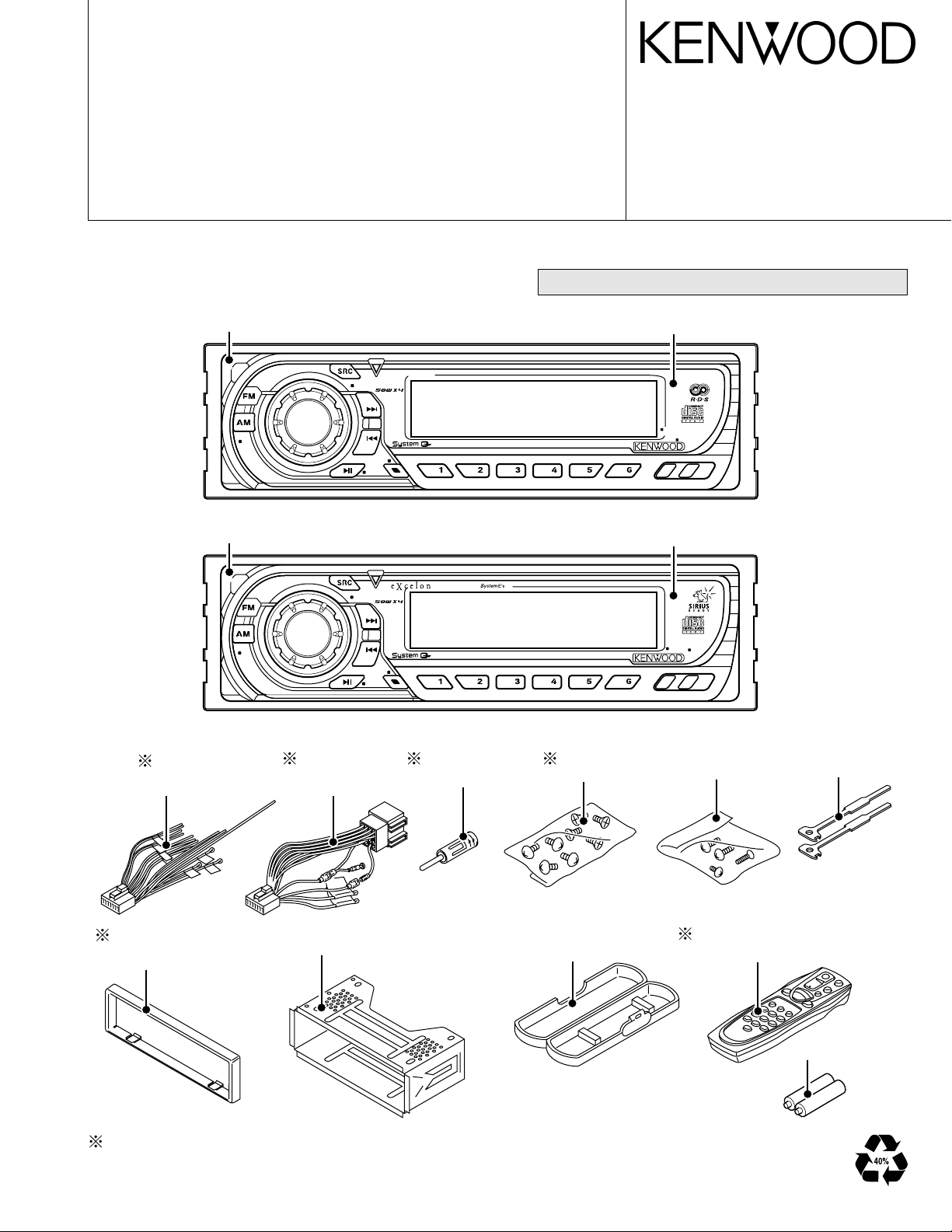
Front glass
(B10-4307-01 : KDC-X469)
Panel assy
(A64-2827-02 : KDC-X469)
KDC-6024
OFF
NF
-
+
DAB
F.SEL
M.RDM
REPSCAN
RDM
AUD
PTY
MENU
NAME.S
DISP
TI
GSM
Front glass
(B10-4313-01 : KDC-6024/6024Y)
Panel assy
(A64-2837-02 : KDC-6024/6024Y )
Escutcheon
(B07-3022-02)
(B07-3075-02)
Plastic cabinet assy
(A02-1486-13)
Mounting hardware assy
(J21-9716-03)
DC cord
(E30-4944-05)
(E30-4958-05)
Antenna adaptor
(T90-0523-05)
Screw set
(N99-1730-15)
Lever
(D10-4589-04)
Depends on model. Refer to the parts list.
DC cord
(E30-4939-05)
Remote controller assy(RC-505)
(A70-2040-05)
Screw set
(N99-1719-15)
Not supplied
•CD MECHANISM OPERATION DESCRIPTION is not in this sevice manual.
Please refer to service manual for X92-4450-0X (B51-7889-00).
CD mechanism extension cord (24PIN) : W05-0934-00
©
2003-1 PRINTED IN JAPAN
B53-0026-00 (N)3114
CD RECEIVER
KDC-6024/Y
KDC-X469
SERVICE MANUAL
KDC-6024/Y/X469
2
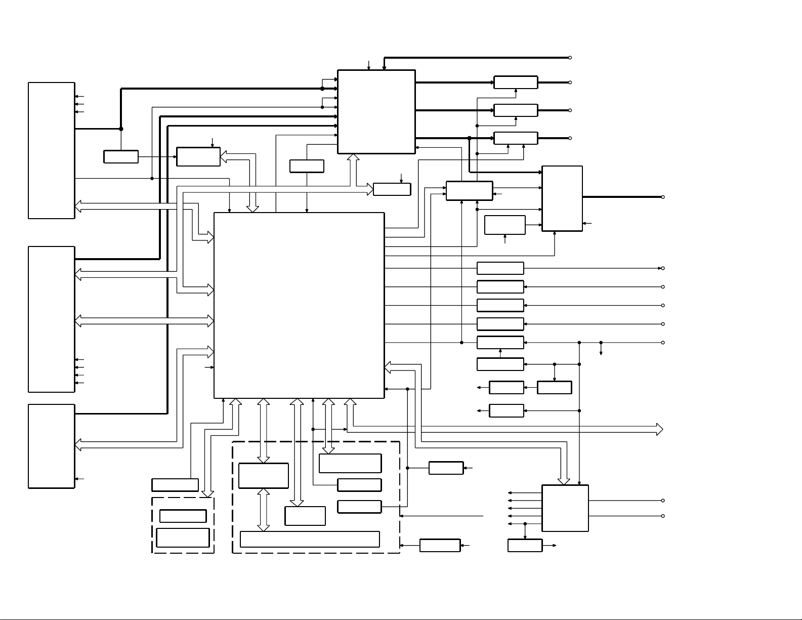
BLOCK DIAGRAM
BUFFER
Q101
RDS
DECODER
IC7
Q201
BUFFER
EEPROM
IC10
IC1
(V-ILL ONLY)
DA CONVERTER
IC3
IC2
REMOCON
RESET SW
ENCODER
ROTARY
S24
WITH
LCD DRIVER
KEY MATRIX
IC1
LCD
PANEL DET
S1
EJECT SW
S1
EJECT ILLUMI
DSI
u-COM
IC2
MPX
E-VOL
&
EXT AMP
DIMMER
ACC DET
TEL MUTE
B.U DET
PRE MUTE
PRE MUTE
PRE MUTE
DRIVER
MUTE
IC6
POWER
IC
IC4
THERMAL
PROTECT
PRE OUT
(REAR/NF)
EXT.AMP.CON
DIMMER
ACC
TEL MUTE
BACK UP
AUX IN
(REAR) 3PRE
PRE OUT
(FRONT)
PRE OUT
SP OUT
SURGE DET
SW REG
CD MECHA+B
SERVOSERVO+B
SW 14V
Q21
IC9
OPEL DISP I/F
WIRED REMO/
SUPPLY
IC
IC3
POWER
ANT DET
P CON
RESET
IC8
SW 5V
Q4
PANEL 5V
Q152
SW5V
S-METER
AUDIO OUT
IFC OUT
PLL-DATA
PLL-CLK
SW5V
AM+B
A8V
SW3
SW2
SW1
MS CLK
MS DATA
M MUTE L
SW4
M MUTE R
LO/EJ
M STOP
MOSW
M RST
SERVO+B
A8V
BU5V
CD MECHA+B
DATA C
CH MUTE
CH RST
REQ H
REQ C
CH CLK
CH-CON
DATA H
BUCK UP
NOISE
QUAL
S-METER
R DATA
R CLK
FM
AM
MP IN
LEVEL
CD
QUAL
AFS
CH
SW5V
SW5V
BU5V
PANEL DET
EJECT
DSI
L CLK
L DATAS
L CE
L DATAL
VOL A
VOL B
REMO
V DATA
V CLK
O-CE
O-DATA
O-CLK
PRE MUTE
MUTE
P-MUTE
EXT.AMP.CON
DIMMER
PHONE
ACC DET
B.U DET
BEEP
PS1-0
PS1-1
PS1-2
PS2-0
PS2-2
RST
FREE
REAR
FRONT
BU5V
BUCK UP
A8V
AUX
SW5V
BACK UP
AM+B
FM+B
ILLUMI
A8V
BU5V
BU5V
BU5V
TUNER
CD
EX.CH
SWITCH UNIT (X16- )
DAUGHTER UNIT
(X89- )
KDC-6024/Y/X469
3
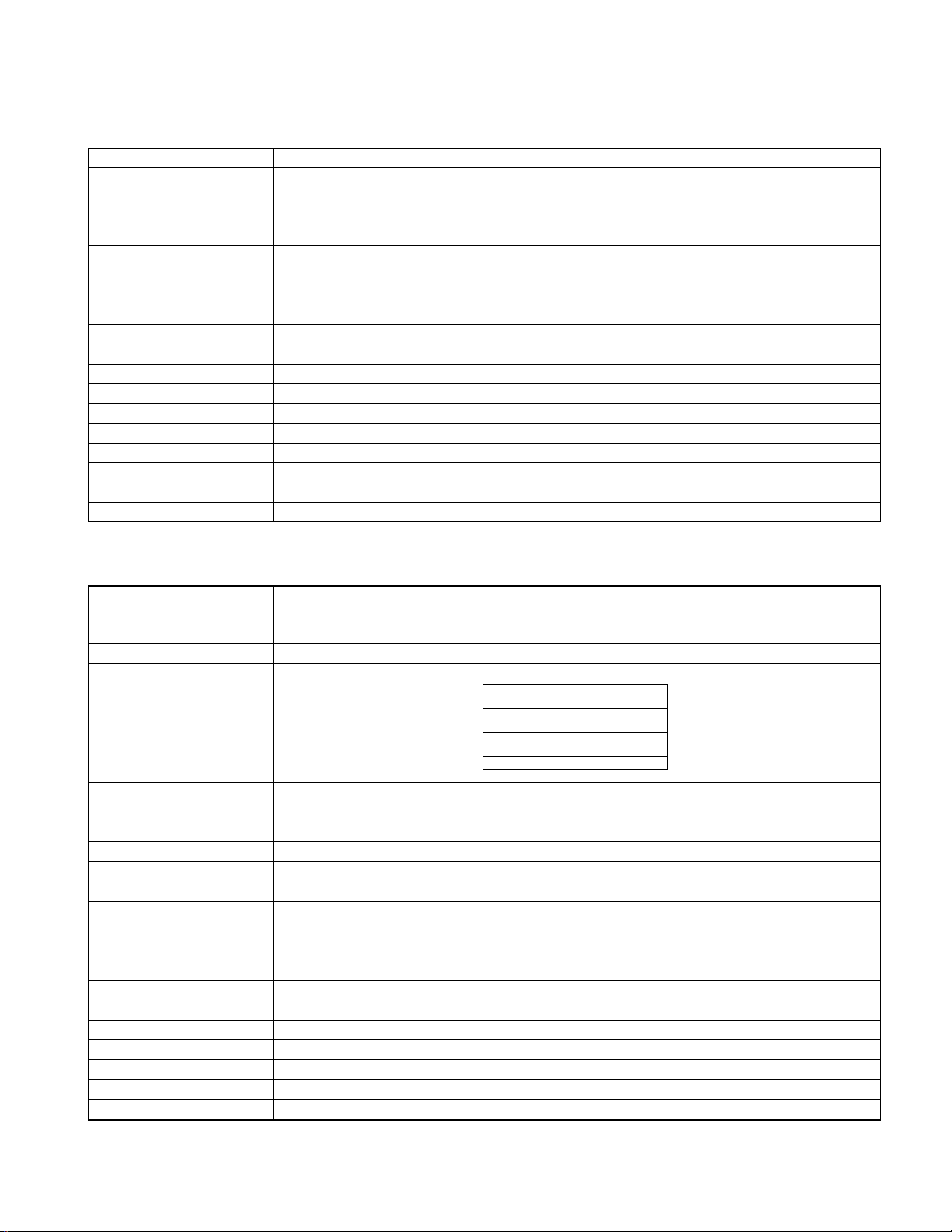
COMPONENTS DESCRIPTION
● CD PLAYER UNIT (X32-5200-00)
Ref.No.
Component Name Application/Functions Operation/Condition/Compatibility
IC1 AN22002AA RF amplifier adapted for CD-RW Generation of RF signal based on the signals from the APC circuit and
pickup, and generation of servo error (focusing error and tracking error)
signals. Detection of dropout, anti-shock, track crossing and off-track
conditions, included gain control function during CD-RW.
IC2 MN6627774KH2
CD signal processor built-in MI-COM
Focusing, tracking, sled and spindle servo processing. Automatic
adjustment (focusing, tracking, gain, offset and balance) operations.
Digital signal processing (DSP, PLL, sub-codes, CIRC error correction,
audio data Interpol ration) operations, and Microcomputer function.
IC4 BA5824FP 4CH BTL driver Focusing coil, tracking coil, spindle motor and sled motor driver, disc
loading and eject operation.
IC6 NJM4580M1 Low pass filter 2nd low pass filter for audio signals
Q1 MCH6101 APC LD power control
Q2 DTC124EUA D.5V SW When P ON signal gose"L", Q2 is ON
Q3 DTA143XUA Q4 SW When P ON signal gose"L" (SW+5V AVR is ON), Q3 is ON
Q4 2SA1362(Y) A.8V SW When P ON signal gose"L" (Q3 is ON), Q4 is ON
D1 DAN202U Protection diode Laser diode protection
D2 MA8051-L Zener diode DAC AVR/LPF reference voltage (A.5V)
D3 DA204U Current driver Current driver
● ELECTRIC UNIT (X25-9712-71/9800-10/9802-71)
Ref.No.
Component Name Application/Functions Operation/Condition/Compatibility
IC1 UPD703030GC013 System microcomputer Control for TUNER unit, CD mechanism, volume & tone, LCD driver and
external CD changer unit
IC2 TDA7411 Electronic volume & N.C.MPX Control for source selector, volume & tone, and FM multiplex detector.
IC3 BA4911-V4 Power supply IC
Power supply for the units (Bu5V, Audio8V, FM+B, AM+B, P-con and ANT-con).
IC4 TA8273H Audio power amp IC
Amplifier for audio signal to derive for 4channel speakers (50W maximum
for each channel).
IC6 HD74HC27FP Muting control IC Control for timing for mute.
IC7 SAA6581T RDS decoder Decode for RDS signal.
IC8 PST3436UL Reset IC When detection voltage goes below 3.5V or less Reset IC output change
to "L" signal.
Q1 2SC4081 Serge detection When backup voltage become more than 24V output is "L" (momentary
power down) / When backup voltage become less than 24V output is "H".
Q2 2SC4081 Backup detection When BU voltage supplied output is "L" / When BU voltage not supplied
or momentary power down is detected output is "H".
Q3 2SC4081 ACC detection When ACC voltage supplied output is "L".
Q4 2SA1036K SW 5V When base voltage is "L" Q4 is ON.
Q21 2SD2375 AVR Servo regulator.
Q22 UMC2N SW Servo SW.
Q23 UMC2N IC control Power supply IC controller.
Q31 UN5213 Dimmer control When base voltage is "H" dimmer is ON.
Q32 DTA123JK EXT. AMP control Control to EXE.AMP for pulse width signal.
SW1 OUT
1.5-3.0V Audio ON
3.5-5.0V Audio, P-con ON
7.0V- Audio, P-con, P-ant ON
SW2
2.0-3.0V Illumination, FM ON
4.0V- Illumination, AM ON
KDC-6024/Y/X469
4
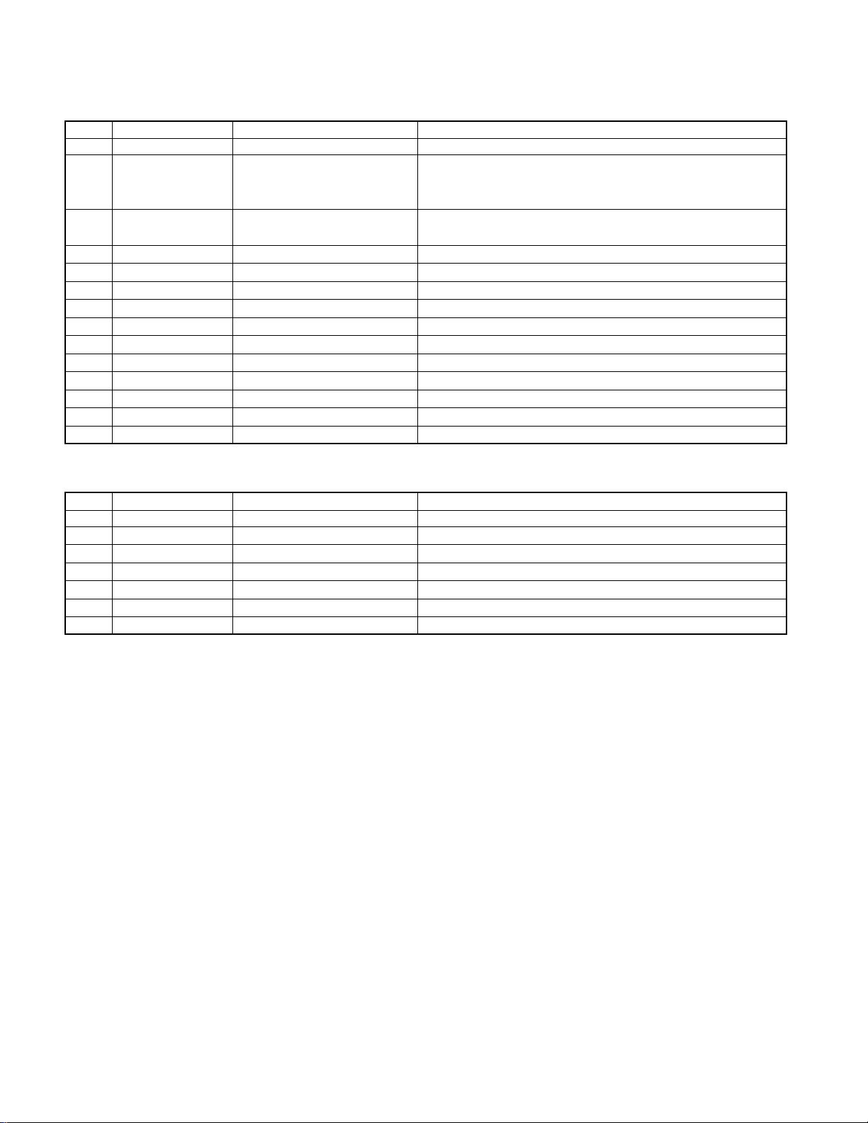
COMPONENTS DESCRIPTION
Ref.No.
Component Name Application/Functions Operation/Condition/Compatibility
Q101 UN5216 Buffer amp COMPOSITE SIGNAL BUFFER.
Q151 UN5114 DSI driver When base voltage level is "L" DSI LED is light up / When base voltage
level is "H" DSI LED turns off / When panel assy is pull off, cut off the
supply to panel 5V AVR.
Q152 2SA1576A Panel 5V SW When panel assy attached to the unit, Q152 base goes "L" and supply to
panel 5V AVR to panel assy .
Q153 UN5213 Illumination control When Q153 base voltage to "H", illumination is light up.
Q154 2SA1577 Illumination control When Q153 base voltage to "H", illumination is light up.
Q201 UN5216 Buffer amp Noise buffer amp.
Q350 UN5112 Pre & NF mute SW When base voltage to "L", drive to pre & NF mute SW(Q351,355,357).
Q351 UN5216 Pre mute SW When base voltage to "H", muting to the pre Lch or NF Lch line.
Q352 UN5216 Pre mute SW When base voltage to "H", muting to the pre Rch or NF Rch line.
Q354 UN5112 Pre & NF mute SW When base voltage to "L", drive to pre & NF mute SW(Q32,356,358).
Q355 UN5216 Pre mute SW When base voltage to "H", muting to the front Lch line.
Q356 UN5216 Pre mute SW When base voltage to "H", muting to the front Rch line.
Q357 UN5216 Pre mute SW When base voltage to "H", muting to the rear Lch line.
Q358 UN5216 Pre mute SW When base voltage to "H", muting to the rear Rch line.
● SWITCH UNIT (X16-2020-10/12/2222-70)
Ref.No.
Component Name Application/Functions Operation/Condition/Compatibility
IC1 LC75808W LCD driver Drive for LCD unit.
IC2 PNA4S22M Remote control IC Receiving for the remote control unit.
Q1 2SC4081 VLCD AVR When base voltage level goes 7.9V Q1 is ON.
Q2 DTA114EUA Remo. ON SW When base voltage level goes "L" the power supply IC2 is turned "ON".
Q3 2SC4081 key illumination SW Lights up for green key illumination when base voltage level goes "H".
Q4 2SC4081 key illumination SW Lights up for red key illumination when base voltage level goes "H".
Q5 2SC4081 Dimmer control SW Lights up for LCD back light when base voltage level goes "H".
KDC-6024/Y/X469
5
MICROCOMPUTER'S TERMINAL DESCRIPTION
Pin No. Name I/O Description/Processing Operation
1 PLL CLK O CLK output terminal to Front End
2 N.C - Open
3 PANEL DET I Panel assy detect terminal ( Panel assy come off : L)
4 IC2 SDA I/O Control Data input / output terminal for electric volume, CD mechanism
5 IC2 SCL O Clock DATA output terminal for electric volume, CD mechanism
6 VDD - Power supply input terminal (BU 5V)
7 VSS - GND
8 FLIP-DET I Panel assy open detect terminal (panel close : L )
9 BEEP O Beep audio signal output terminal
10 REMO I Remote control signal input terminal
11 R QUAL I RDS decoder QUAL signal input terminal
12 R DATA I RDS decoder Data signal input terminal
13 L CE O CE output for LCD driver IC
14 VILL DATA O Variable illumination DATA out put terminal for D/A converter
15 VILL CLK O Valuable illumination CLK out put terminal for D/A converter
16 DSI O Disc guide illumination control terminal
17 DIM CON O Dimmer control terminal
18 TEST - Test terminal
19 ILL CON O Illumination control terminal
20 VOL A I Volume key input terminal
21 VOL B I Volume key input terminal
22 MOSW O CD mechanism motor IC control output terminal (Loading,eject ,brake :L )
23 LO/EJ O CD mechanism loading / eject control terminal
24 M STOP O Request signal (Mechanism is STOP) output to CD mechanism (active L)
25 M RST O Reset signal output to CD mechanism (active L)
26 MUTE O Muting signal output terminal
27 LOE/LIM SW I Down SW detection from CD mechanism
28 M-MUTE L I Request for muting signal from CD mechanism (Mute request : L )
29 M-MUTE R I Request for muting signal from CD mechanism (Mute request : L )
30 PANEL 5V O Control for Panel5V AVR
31 RESET I Reset terminal (Active : L )
32 XT1 I Sub clock input terminal (32.768KHz)
33 XT2 I Sub clock input terminal (32.768KHz)
34 REGC - Regulator output terminal
35 X2 I Main clock input terminal (20MHz)
36 X1 I Main clock input terminal (20MHz)
37 VSS - GND
38 VDD - Power supply input terminal (BU 5V)
39 NC - Open
40 IC2 TYPE1 I Electric volume condition setting terminal
41 IC2 TYPE0 I Electric volume condition setting terminal
42 TYPE2 I Destination setting terminal
43 TYPE1 I Destination setting terminal
44 TYPE0 I Destination setting terminal
45 CD MECHA+B O AVR control for CD mechanism ( For MP3 AVR ON :L )
46 SW 5V O Control terminal for SW5V AVR (ON : L , OFF : Hi-Z)
47 PS2-0 O Power supply IC control terminal
48 PS2-1 O Power supply IC control terminal
49 PS1-0 O Power supply IC control terminal
50 PS1-1 O Power supply IC control terminal
● IC1: ELECTORIC UNIT (X25-9712-71/9800-10/9802-71)
KDC-6024/Y/X469
6
MICROCOMPUTER'S TERMINAL DESCRIPTION
Pin No. Name I/O Description/Processing Operation
51 PS1-2 O Power supply IC control terminal
52 B.U-DET I BU detect input terminal ( BU detect : L )
53 ACC-DET I ACC detection input terminal (ACC detect : L)
54 DIMMER I Illumination detect terminal from CAR (illumination ON : L )
55 BVDD - Power supply input terminal (BU 5V)
56 BVSS - Open
57 EXT AMP CON O EXT. amp control terminal (Active H)
58 SVR O SVR control for Audio power IC
59 P-MUTE O Muting control for Audio power IC
60 P-STBY O STBY control for Audio power IC (Power IC ON : H )
61 NC - Open
62 PRE MUTE R O Rch pre mute output terminal (Active H)
63 PRE MUTE L O Lch pre mute output terminal (Active H)
64 TUNER O Noise detection (FM seek,AM search : L )
65 O-DATA O DATA signal output for EXT. display (Handling for OPEL display)
66 O-CLK O CLK signal output for EXT. display (Handling for OPEL display)
67 O-CE O CE signal output for EXT. display (Handling for OPEL display)
68 LX-RST O Reset signal output to EXT. unit
69 LX-CON O Control signal output to EXT. unit (ON : H , OFF : L)
70 AVCONT O Control for A/D reference voltage
71 AVDD - Power supply input terminal (BU 5V)
72 AVSS - Open
73 AVREF I A/Dereference voltage input terminal
74 PHONE I Mobil phone detection input terminal
75~81 NC - GND
82 S-METER I S meter detection input terminal
83 NOISE I FM noise detection input terminal
84 IFC-OUT I IFC OUT input terminal
85 LX-MUTE I Request signal input terminal from EXT.unit (Mute ON : L )
86 LX-REQ-M O Request signal output terminal to EXT.unit (Request : L)
87 R-CLK I RDS decoder CLK input terminal
88 LX-REQ-S I Request signal input terminal from EXT.unit (Request : L)
89 KEY-REQ I Request for communicate from LCD driver IC (KEY input : L )
90 LO.S SW I Loading start SW detection input terminal (Loading start : L )
91 12EJE SW I 12cm CD disc eject SW detection input terminal (12cm disc : L )
92 EJECT I Eject detection terminal (KEY input : L)
93 8EJE SW I 8cm CD disc eject SW detection input terminal (Not used)
94 LX-DATA-S I DATA signal input from EXT. unit
95 LX-DATA-M O DATA signal output to EXT. unit
96 LX-CLK I/O CLK signal input/output to EXT. unit
97 L DATAL I DATA input terminal from LCD deriver IC
98 L DATAS O DATA output terminal to LCD driver IC
99 L CLK O CLK output terminal to LCD driver IC
100 PLL DATA I/O Data input / out put terminal to Front-end

KDC-6024/Y/X469
7
TEST MODE
1. How to enter the test mode
• While holding the preset 1 key and 3 keys, reset the unit.
2. How to exit from the test mode
• Reset the unit, ACC OFF, power OFF, and come off the
front panel assy for the unit.
3. Initial status in the test mode
• Sources : All OFF.
• Display : All segments were lit.
• Volume : -10 dB (displayed as 30)
• Loudness : OFF
•CRSC : OFF regardless of the presence of
switching function.
• SYSTEM Q : Flat.
• Aux : ON
• Display color : white (variable color display model only)
• Beep sound : ON
4. Special display in Tuner mode
When any of the following messages is displayed in Tuner
mode, the Front-end (F/E) may be bad condition.
• "TNE2P NG": The EEPROM is set to the default (unstable
values) because the F/E was shipped without passing
through the adjustment process, etc.
• "TNCON NG": Communication with the F/E to microprocessor is not possible.
5. Forced switching of K3I
Each press of the Preset 6 key in Tuner mode should
switch K3I from AUTO → Forced Wide → Forced Middle →
Forced Narrow → AUTO. The initial status is AUTO and
the display shows these modes as follows.
• AUTO : FMA
• Forced Wide : FMW
• Forced Middle : FMM
• Forced Narrow : FMN
6. Test mode specifications of the CD receiver
• Forced ejection is inhibited in the reset start operation.
When the unit is reset while a CD is loaded in it, the CD is
not recognized by resetting.
• Each press of the Track Up key jumps to the following
track numbers:
No. 9 → No. 15 → No. 10 → No. 11 → No. 12 → No. 13 →
No. 22 → No. 14 → No. 9 (The cycle restarts from here.)
• Each press of the Track Down key jumps to the previous
track number to the track being played.
• When the number of total tracks of an MP3 disc is nine or
less, unit playback from a track 1.
• When the media to CD-DA, unit playback from track No.28
by key operation of preset 1 key.
7. Audio-related specifications
• A short press of the Q key initiates the audio adjustment
mode.
• Pressing the
✽ key on the remote initiates the audio ad-
justment mode.
• Continuous holding of a remote control key is inhibited.
• Bass, Middle and Treble are adjusted in 3 steps of -8 / 0 /
+8 with the Track Up/down keys (default is 0).
• Balance is adjusted in 3 steps of Left L15 / 0 / R15 Max
with the Track Up/down keys (default is 0).
• Fader is adjusted in 3 steps of Rear15 / 0 / F15 Max with
the Track Up/down keys (default is 0).
• HPF is adjusted in 2 steps of Through/170Hz (or 200Hz)
with the Track Up/down keys (default is through).
• LPF is adjusted in 2 steps of Through/120Hz with the Track
Up/down keys (default is through).
• Bass f, Bass Q, Bass EXT, Middle f, Middle Q and Treble
f are not dealt with by the audio adjustment.
8. Menu-related specifications
• A short press of the PLAY/PAUSE key initiates the Menu
mode.
• Pressing the DNPP key on the remote initiates the Menu
mode.
• Continuous holding of a remote control key is inhibited.
• Contrast is adjusted press of the Track up/down key in 3
steps of 0 / 5 / 10 (default is 5).
9. Backup current measurement
When the unit is reset while ACC is OFF (i.e. by turning
Backup ON), the MUTE terminal goes OFF in 2 seconds in
place of 15 second. (The CD mechanism is not activated at
this time.)

KDC-6024/Y/X469
8
TEST MODE
10. Special display when the display is all on
Pressing the Preset keys while the power is ALL OFF displays the following information.
11. Change the condition of TUNER channel
space selection (K/M type only)
While holding the preset 1 key and 5 keys, reset the unit.
Security-related information
1. Forced Power ON mode (All models)
Even when the security is approved, resetting the unit while
holding the Q and Preset 4 keys makes it possible to turn
the power ON for 30 minutes.
After 30 minutes have elapsed, it is not possible to return to
the previous condition unless the unit is reset again.
2. Method of registration of the security code
after EEPROM (Tuner unit assy) replacement
(Code security model)
1. Enter the test mode. (See 1. How to enter the test mode)
2. Press the MENU key to enter the MENU mode.
3. Press and hold down the Track up/down key for 1 second
until “Security” is displayed.
4. Enter the code using the FM/AM/TARCK up/down keys.
• FM key: number is up
• AM key: number is dawn
• Track up key: move the cursor for right side
• Track down key: move the cursor for left side
5. Hold down the Track up key for at least 3 seconds and
the message, "RE-ENTER" appears, so once again enter
the code according to Step 3 above.
6. Press and hold the Track up key for 3 seconds until
"APPROVED" is displayed.
7.
Exit from the test mode. (See 2. How to exit from the test mode)
(Note) All Clear is not applicable to the security code of
this model.
3. Simplified method of clearing the security
code (K, E Type only)
1. While the code entry is requested, press and hold the
TRACK UP key for 3 seconds while holding the DISP key
pressed. (This should turn "----" off.)
2. Enter “KCAR “from the remote.
• Press the 5 key on the remote twice, and then press the
Track Up key. (This enters "K".)
• Press the 2 key on the remote 3 times, and then press
the Track Up key. (This enters "C".)
• Press the 2 key on the remote once, and then press the
Track Up key. (This enters "A".)
• Press the 7 key on the remote twice, and then press the
Track Up key. (This enters "R".)
3. The security code is cleared and the unit enters the ALL
OFF mode.
4. If you commit a mistake in the code entry, the unit enters
the code request mode again.
Version display (8 digits, Month/Day/Hour/Minute)
(Display) SYS xxxxxxxx
Serial No. display (8 digits)
(Display) S. No. xxxxxxxx
Short press: View power ON time.
(The All OFF period is not counted.)
Long press/hold: Clear power ON time.
(Display) PonTim xxxxx Max. 60,000 (hours)
Short press: Display CD operation time.
Long press/hold: Clear CD operation time
(Display) CDTime xxxxx Max. 60,000 (hours)
Short press: Display CD ejection count.
Long press/hold: Clear CD ejection count.
(Display) EjeTim xxxxx Max. 60,000 (times)
Short press: Display Panel open/close count.
Long press/hold: Clear Panel open/close count.
(Display) PnCnt xxxxx Max. 60,000 (times)
ROM correction version information
(Display) ROM Rxxxx
If not mounting ROM correction chip set display
shows ROM R_
PRESET 1
PRESET 2
PRESET 3
PRESET 4
PRESET 5
PRESET 6
FM
9
A B C D E
1
2
3
4
5
6
7
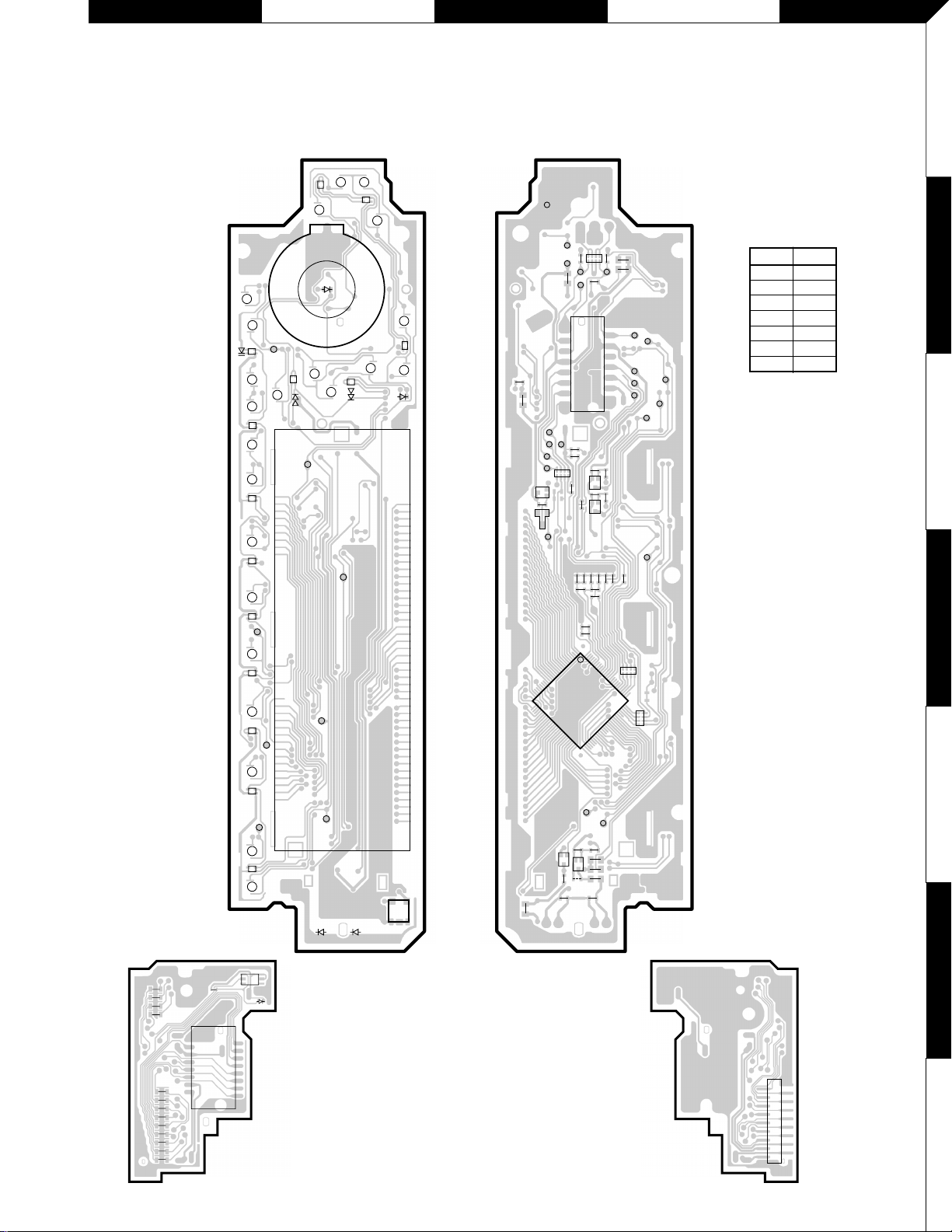
PC BOARD
(COMPONENT SIDE VIEW) (FOIL SIDE VIEW)
Ref. No address
IC1 4C
IC2 6B
Q1 3C
Q2 5C
Q3 3C
Q4 3C
Q5 5C
X16-2020-10
/12/2222-70
Refer to the schematic diagram for the values of resistors and capacitors.
KDC-6024/Y/X469
1
KS5
AM
FM
RST
AUD
1 2 3 4 5 6 DISP AUTO
SRC
KS3
KI4
KI2
KI1
KI3
KI5
KS3
91024
45
31
69 25
D10
D11
S24
SWITCH UNIT
X16-2020-10/12/2222-70 (J74-1448-22)
D7
D13
D9
D6
D5
D4
D1
D2
D3
IC2
D8
D14
D12
ED1
D16
D15
D18
D17
SWITCH UNIT
X16-2020-10/12/2222-70 (J74-1448-22)
R23
ESD-GND
KS4
ILL +B
FLIP DET
VOL B
VOL A
RESET
KI3
ILL GND
DIMMER
REMO
KI4
KI2
KS5
PANEL 5V
DO
CE
CL
DI
D-GND
KI1
KI5
KS3
R24
R9
R16 R18
BE
BE
BE
R15
R2C2C3C4C5
C6
R29
C11
C10
1
2
16
15
CP1
C9
R25
R22
C8
R6
R19
R17
R11
CP3
R1
C1
CP5
CP4
1 100
76
75
51
R28
W1
R27
R21
R20
R26
C13
C12
C7
R13
50
26
25
R10
R3
R4
R5
J1
Q1
EB
Q4
EB
Q3
D19
IC1
Q2
Q5
R2
C1
1
15
16
2
R1
R3
R4
R11
R6
R13
R7
R5
R12
R9
R10
R8
D1
J1
DAUGHTER UNIT
X89-2570-10/2602-70 (J74-1450-02)
S1
17
1
2
18
CN1
DAUGHTER UNIT
X89-2570-10/2602-70 (J74-1450-02)
F G H I J
1
2
3
4
5
6
7
R358
9106751
1
9
8
16
1
25
224
13 11 12 8 4 3 2
R363
1
1
24
1
117
2
2
24 2
23 1
18
133
4
6
R361R359
R360
R377
R376
C360
R373
W104
W103
W106
C210
C213
R204
R211
R212
W105
W101
C212
R402
R407
C7
R24
R25
R26
R27
SCL
SDA
R28
R417R416
R412R411
R421R420
R44R43
R409
C405
R63
R42
5
1
R41
C45
R422
R56
R59
R60
R151
R163
R210
R208
R207
R209
R105
R103
R152
R102
R154
R153
R104
R113
C502
R213
C226
C227
R215
C223C225
R214R216
C222C224
R112
R114
C116
C118
R155
R156
R169
R158
R157
R55
R58
R54
R166
R413
R419
R415
R418
C32
C4
R253
R254
R260
R261
TH1
R37
R31
R21
R262
R259
C257
R257
R32
R33
C31
R1
R2
R35
R34
C304
R372
R36
C403
R408
R370
R371
R315
R403
R404
R406
R401
R405
R203
R362
R364
R357
R355
R356
R352
R351
EB
BE
D41
Q351
EB
Q31
Q22
Q352
BE
Q350
BE
Q356
D203
D161
D162
D154
D153 D158
BE
Q41
BE
Q201
BE
Q354
D205 D204
EB
D352
D351
Q357
EB
Q358
BE
Q355
L3
W1
W2
W4
W7
W8
W11
W26
W28
1
12
W10
R8
R9
R22
R23
L1
W29
IC3
W24
W21
W23
W27
W18
W17
W13
W12
W14
W9
BU5V
RST
W16
W19
W22
W25
W15
W20
W30
W33
W31
W34
W32
W5
C256
C33
C258
C22
C20
C21
E
BEE
C
C
C1
C23
C29
C24
C26
C409
C28
C27
C41C42
C44
C43
C25
C301
C352
C351
C354
C353
C359 C358
C211
C216
C117 C115
X3
C221
C220
C208
C207
C209
C202 C201
C217
C219
C218
C355
C255
C254
C302
C303
C251 C252 C253
W3
W6
D1
J1
J3
ELECTRIC UNIT
X25-9712-71/9800-10/9802-71
(J74-1447-12)
J2
J4
CN3
CN4
A1
CN5
P1
S1
CN1
CN2
IC4
85
41
IC10
148
71
IC6
251
75
76
100
50
26
51
IC1
44
18
169
34
22
23
33
11
1
12
IC2
IC7
IC9
D156D155D160D159D152
D157D151
X2
X1
D308
D307
D301
D303
D304
D311
D310
CN6
D270
D269
D271
D32
D4
D31
L9
D21
Q21
D2
D3
D401
D163 D164
D165
D254
D252
D25
D253
D23
D22
D251D255
D24
D256
D257
D258
D309
D357
D356
D358
L8
L7
L6
L10
L11
W35/L2
L12
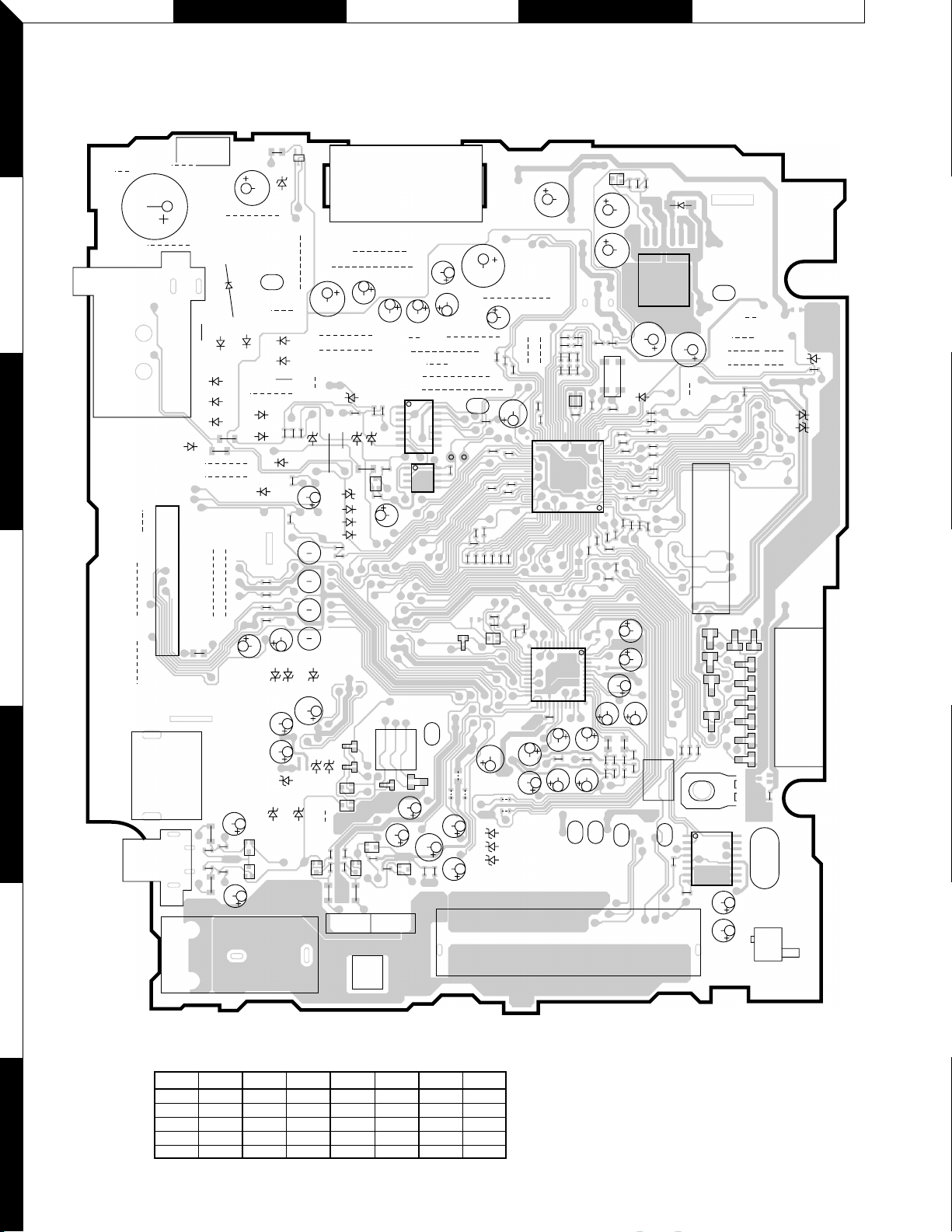
PC BOARD (COMPONENT SIDE VIEW)
10
Refer to the schematic diagram for the values of resistors and capacitors.
KDC-6024/Y/X469
Ref. No address Ref. No address Ref. No address Ref. No address
IC1
IC2
IC3
IC4
IC6
3I
4I
2H
4F
3H
IC7
Q21
Q22
Q31
Q201
5J
1G
1G
3H
4H
Q350
Q351
Q352
Q354
Q355
Q356
Q357
Q358
5H
5G
5G
5H
5G
5H
5H
5H
X25-9712-71/9800-10/9802-71
 Loading...