

Page 1

m
AV SURROUND STEREO AMPLIFIER
KA-V9500
INSTRUCTION MANUAL
KENWOOD CORPORATION
B60-0291-00 QE) CK, M, Y) M
93/87654321 /92/12 11 10 987654321
Ai^niitinn' RaaH thic nnno nnrAfiillv tn ontsiirn finfn nnerntinn.
Page 2
Introduction
Your choice of this product indicates that you are a devotee
to excellence in sound reproduction.
We appreciate your patronage and take pride in the long tradi
tion of quality components that our company represents.
So that you can get the most out of your unit, we suggest that
you take the time to read through this manual before you hook
up and operate your system. This will acquaint you with oper
ating features and system-connection considerations so that
your listening pleasure will be enhanced right from the start.
You will notice that in all aspects of planning, engineering,
styling, operating convenience and adaptability we have sought
to anticipate your needs and desires.
Keep this manual handy for future reference.
For your records
Record the serial number, found on the back of the unit, in
the spaces designated on the warranty card, and in the space
provided below. Refer to the model and serial numbers
whenever you call upon your dealer for information or service
on this product.
Model
________________
Unpacking
Unpack the unit carefully and make sure that ail accessories
are put aside so they will not be lost.
Examine the unit for any possibility of shipping damage. If your
unit is damaged or fails to operate, notify your dealer immedi
ately. If your unit was shipped to you directly, notify the ship
ping company without delay. Only the consignee (the person
or company receiving the unit) can file a claim against the car
rier for shipping damage.
We recommend that you retain the original carton and pack
ing materials for use should you transport or ship the unit in
the future.
Serial Number
__________________
Accessories
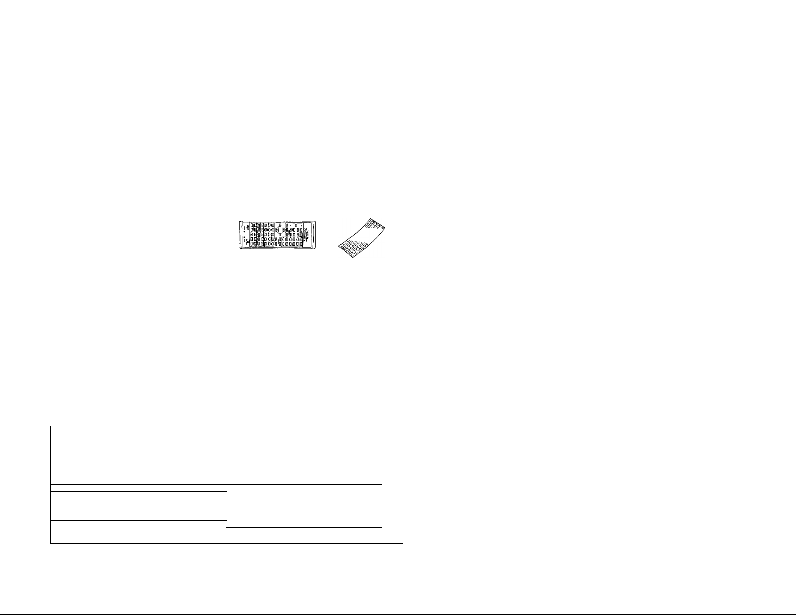
I Remote control unit... 1 ► Remote control unit entry
> Batteries
(R03/UM-4/"AAA") ... 4
sheet ... 1
► AC plug adaptor ... 1
(Except for some areas.)
For the unit with a European
AC plug in areas other than
Europe.
ContBIltS Caution: Read the pages marked ^ carefully to ensure safe operation.
Introduction
^Before applying power ........................
¿íiSafety precautions
^IMPORTANT SAFEGUARDS
System connections ................................................. ........ 6
Controls and indicators
Remote control operation................................................
On-screen character display............................................
Playing back an audio source
Recording an audio source .
Recording an audio source while listening to
another
Playing back a video source
......
.............................................
............................................
...
.......... .........................................................
......................
.......................................
..................................
___________—
..................
.. 2 Recording a video source
........... 3
.........
3
.
.........
4
...... 10
.
.........
12
.
.........
17
.
........
18 DSP and DSP.LOGIC playback............................................
.
... .... 20
.........
21 In case of difficulty
.........
22
2 KA-V9500 (Enl
................
.......
.............
Independent audio/video recording from
source being played
Parametric equalizer operation .... 26
Presence feature
DOLBY PRO LOGIC, 3 STEREO adjustments
Playback with DOLBY PRO LOGIC or 3 STEREO ...
DSP Presence ......................................................................
Surround information Memory............................................... 38
Title Edit function
Specifications.....................................................................
.......................
..........................
..................................................................
................................................................
.......
.
....................
... 23
.
.^25
.... 30
.... 32
. 33
.... 41
28
36
39
42
Page 3
Before applying power
A Caution: Read this page carefully to ensure safe operation.
For the U.S.A. and Canada
Units shipped to the U.S.A, and Canada are designed for opera
tion on 120 voits AC only.
Safety precaution for a Polarized AC plug
However, some products may be supplied with a non-poiarized
plug.
CAUTION: TO PREVENT ELECTRIC SHOCK DO NOT USE
THIS (POLARIZED) PLUG WITH AN EXTENSION CORD,
RECEPTACLE OR OTHER OUTLET UNLESS THE BLADES CAN
BE FULLY INSERTED TO PREVENT BLADE EXPOSURE.
For the United Kingdom
Units shipped to the U.K. are designed for operation on
240 volts AC only,
The mains plug must be removed from the wall socket prior
to any internal examination.
The wires in this mains lead are coloured in accordance with
the following code:
Blue
.......................................................
Brown................................................... Live
The wires in this mains lead must be connected, to the termi
nals in the plug as follows;
Wire colour Plug terminal marking
Blue
................................................ N or Black
Brown ...................................................
2. if a 3-pin plug with earthing contact is used, no wire must
be connected to the E termina!.
Important!
important!
Neutral
L or Red
For Austraiia and Europe
Units shipped to Australia are designed for operation on 240 V
AC only.
Units shipped to Europe are designed for operation on 220 V
AC only.
For other countries
Units shipped to countries other than the above countries are
equipped with an AC voltage selector switch on the rear panel.
Refer to the following paragraph for the proper setting of this
switch.
AC voltage selection
This unit operates on 110-120 or 220-240 volts AC, The AC
voltage selector switch Type A or Type B on the rear panel is
set to the voltage that prevails in the area to which the unit
is shipped. Before connecting the power cord to your AC out
let, make sure that the setting position of this switch matches
your line voltage. If not, it must be set to your voltage in ac
cordance with the following direction.
Note:--------———
Our warranty does not cover damage caused by excessive line
voitage due to improper setting of the AC voltage selector
switch,
Type A
Type B
Move switch lever to match your line voltage with
a small screwdriver or other pointed tool.
This unit has two AC voltage selector switches.
Be sure to set both of them together whenever
the AC voltage switching is required.
Important!
Important!
--------------------------------------
AC voltage selector switch
AC110-
AC220V- AC240V-
AC110V-^^AC220V-
120V- 240V-
—_____
Safety precautions
WARNING
TO PREVENT FIRE OR SHOCK HAZARD,
TO RAIN OR MOISTURE.
A 1 1 A
A
A
DO NOT EXPOSE THIS APPLIANCE
CAUTION; TO REDUCE THE RISK OF ELECTRIC SHOCK, DO NOT REMOVE
COVER (OR BACK). NO USER-SERVICEABLE PARTS INSIDE, REFER SER
VICING TO QUALIFIED SERVICE PERSONNEL.
THE LIGHTNING FLASH WITH ARROWHEAD SYMBOL, WITHIN AN EQUILATERAL TRIANGLE,
IS INTENDED TO ALERT THE USER TO THE PRESENCE OF UNINSULATED "DANGEROUS VOL
TAGE" WITHIN THE PRODUCT'S ENCLOSURE THAT MAY BE OF SUFFICIENT MAGNITUDE
TO CONSTITUTE A RISK OF ELECTRIC SHOCK TO PERSONS.
THE EXCLAMATION POINT WITHIN AN EQUILATERAL TRIANGLE IS INTENDED TO ALERT THE
USER TO THE PRESENCE OF IMPORTANT OPERATING AND MAINTENANCE (SERVICING) IN
STRUCTIONS IN THE LITERATURE ACCOMPANYING THE APPLIANCE.
KA-V9500 (tn) 3
Page 4
IMPORTANT SAFEGUARDS
Caution : Read this page carefuiSy to ensure
safe operation.
Please read all of the safety and operating instructions
before operating this unit. For best results, follow all
warnings placed on the unit and adhere to the operat
ing and use instructions. These safety and operating in
structions should be retained for future reference.
1. Power sources — The unit should be connected
to a power supply only of the type described in the
operating instructions or as marked on the appliance.
2. Power-cord protection — Power-supply cords
should be routed so that they are not likely to be
walked on or pinched by items placed upon or
against them, pay particular attention to cords at
plugs, convenience receptacles, and the point where
they exit from the unit.
Never pull or stretch
the cord.
3. Grounding or polarization — The precautions
should be taken so that the grounding or polariza
tion means of this unit is not defeated.
4. Ventilation — The unit should be situated so that
its location or position does not interfere with its
proper ventilation.
To maintain good ventilation, do not put records or
a table-cloth on the unit. Place the unit at least
10 cm away from the walls.
Do not use the unit on a bed, sofa, rug or similar
surface that may block the ventilation openings.
7. Heat — The unit should be situated away from
heat sources such as radiators, heat registers,
stoves, or other units {including amplifiers) that
produce heat.
8. Electric shock — Care should be taken so that ob
jects do not fall and liquid is not spilled into the en
closure through openings. If a metal object, such as
a hair pin or a needle, comes into contact with the
inside of this unit, a dangerous electric shock may
result. For families with children, never permit chil
dren to put anything, especially metal, inside this
unit.
9. Enclosure removal — Never remove the en
closure. If the internal parts are touched accidentally,
a serious electric shock might occur.
5. Water and moisture — The unit should not be
used near water — for example, near a bathtub,
washbowl, kitchen sink, laundry tub, in a wet base
ment, or near a swimming pool, etc.
6. Temperature — The unit may not function pro
perly if used at extremely low, or freezing tempera
tures. The ideal ambient temperature is above + 5°C
(41 °F).
KA-V9500 (En)
10. Magnetic fields — Keep the unit away from
sources of magnetic fields such as TV sets, speaker
systems, radios, motorized toys or magnetized
objects.
11. Cleaning Do not use volatile solvents such as
alcohol, paint thinner, gasoline, or benzine, etc. to
clean the cabinet. Use a clean dry cloth.
Page 5
ACaution : Read this page carefully to ensure
safe operation.
12. Carts and stands — An appliance and cart com
bination should be moved with care. Quick stops,
excessive force, and uneven surfaces may cause the
appliance and cart combination to overturn.
13. Nonuse periods — The power cord of the unit
should be unplugged from the outlet when left un
used for a long period of time.
14. Abnormal smell — If an abnormal smell or smoke
is detected, immediately turn the power OFF and pull
out the power cord. Contact your dealer or nearest
service center. . _
POWER OFF!
15. Damage requiring service — The unit should be
serviced by qualified service personnel when:
A. The power-supply cord or the plug has been
damaged; or
B. Objects have fallen, or liquid has been spilled into
the unit; or
C. The unit has been exposed to rain; or
D. The unit does not appear to operate normally or
exhibits a marked change in performance; or
E. The unit has been dropped, or the enclosure
damaged.
16. Servicing — The user should not attempt to ser
vice the unit beyond that described in the operating
instructions. All other servicing should be referred
to qualified service personnei.
17. Outdoor antenna grounding -~ If an outside an
tenna is connected to the receiver, be sure the an
tenna system is grounded so as to provide some
protection against voltage surges and buiit up static
charges. Section 810 of the National Electrical Code,
ANSI/ NFPA No. 70 — 1984, provides information
with respect to proper grounding of the mast and
supporting structure, grounding of the lead-in wire
to an antenna discharge unit, size of grounding con
ductors, location of antenna-discharge unit, connec
tion to grounding electrodes, and requirements for
the grounding electrode. See Figure.
18. Power lines — An outdoor antenna should be lo
cated away from power lines.
19. AC outlets — Do not connect other audio equip
ment with a power consumption larger than that
specified to the AC outlet on the rear panel. Never
connect other electrical units, such as an iron or
toaster, to it to prevent fire or electric shock.
The maximum capacities indicated for the AC out
lets on the rear panel of this unit are as follows.
SWITCHED outlets
; 200 W
Notes:-------------------------------------------------------------------------------------------------------------------------
1. Item 3 is not required except for grounded or polarized equipment.
2. Item 17 and 18 are not required except for units provided with antenna terminals.
3. Item 17 complies with UL in the U.S.A.
KA-V9500 (En) 5
Page 6
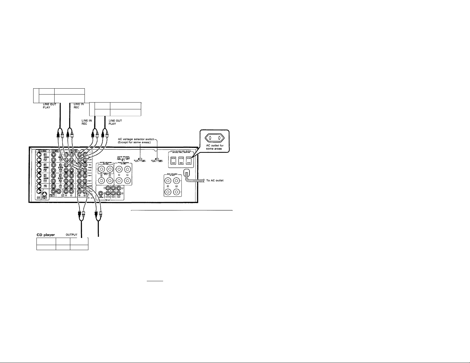
System connections
Make connection as shown in the diagram. When connecting the related system components, refer also to the
instruction manuals of the related components.
Do not plug in the power lead until all connections are completed.
I Connection of audio components
Cassette deck 1
□
i 1
□
1 '------------'
r 1 ■ 1 { o O
□
□
1 fò~òl 1
o o|
Cassette deck 2
1 r;- - ' 1 p
1 r ' r 1° ° T O
External power supply outlets
SWITCHED outlets (total max, capacity 200W):
Connect the power plugs of the tuner, tape deck, or CD player to
these outlets. By leaving the POWER switches of these compo
nents ON, they will be switched ON-OFF at the same time as the
II» »11
□
1
o 1 1 —! o
POWER switch of this unit. Never connect components having a
total combined power consumption of more than total 200 W.
External power
supply outputs
SW1TC(«DT01»L200W MAX. ^
(LJ.
AC outlet for
^some areas
Notes:
1. Connect all cords firmly. If connections are loose there could be loss of sound or noise produced.
2. Do not connect up a power source which is larger than that indicated on the socket at the rear of the unit.
3. When plugging and unplugging connection cords after connections are complete, be sure to first remove the power cord from the AC
outlet. Plugging/unplugging connection cords without removal of the power cord can cause malfunctions or. damage to the unit.
6 KA-V9500 (En)
Page 7
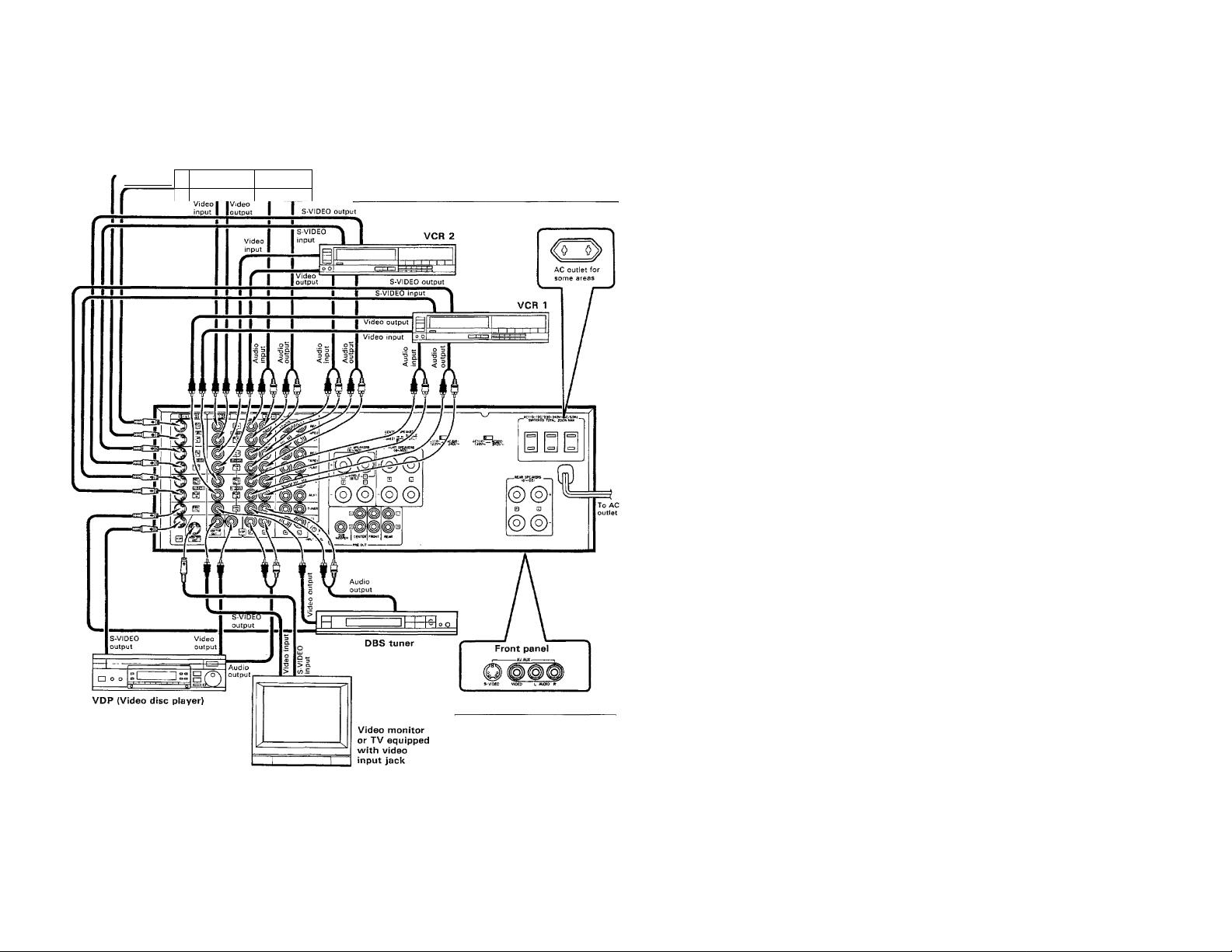
I Connection of vìdeo components
S-VIDEO output
S-VIDEO input
O O
1 1
VCR 3
S-VIDEO jacks:
The S-VIDEO signaling system transmits ordinary video signal
[composite video signal) by separating its components into the
signal representing brightness (Y signal) and signal representing the
colors (C signal). The use of these jacks is recommended to obtain
a better picture quality in your video entertainment. For details,
please read the instruction manual of your VCR.
Note:
Be always sure to connect the S-VIDEO jack and the corresponding VIDEO jacks to i
components may result in disturbed on-screen characters.
AV AUX jacks:
Connect a video camera, etc.
When the R jack is only connected, the
sound is reproduced in monaural.
same component. Connecting them to different
KA-V9500 (En) 7
Page 8
System connections
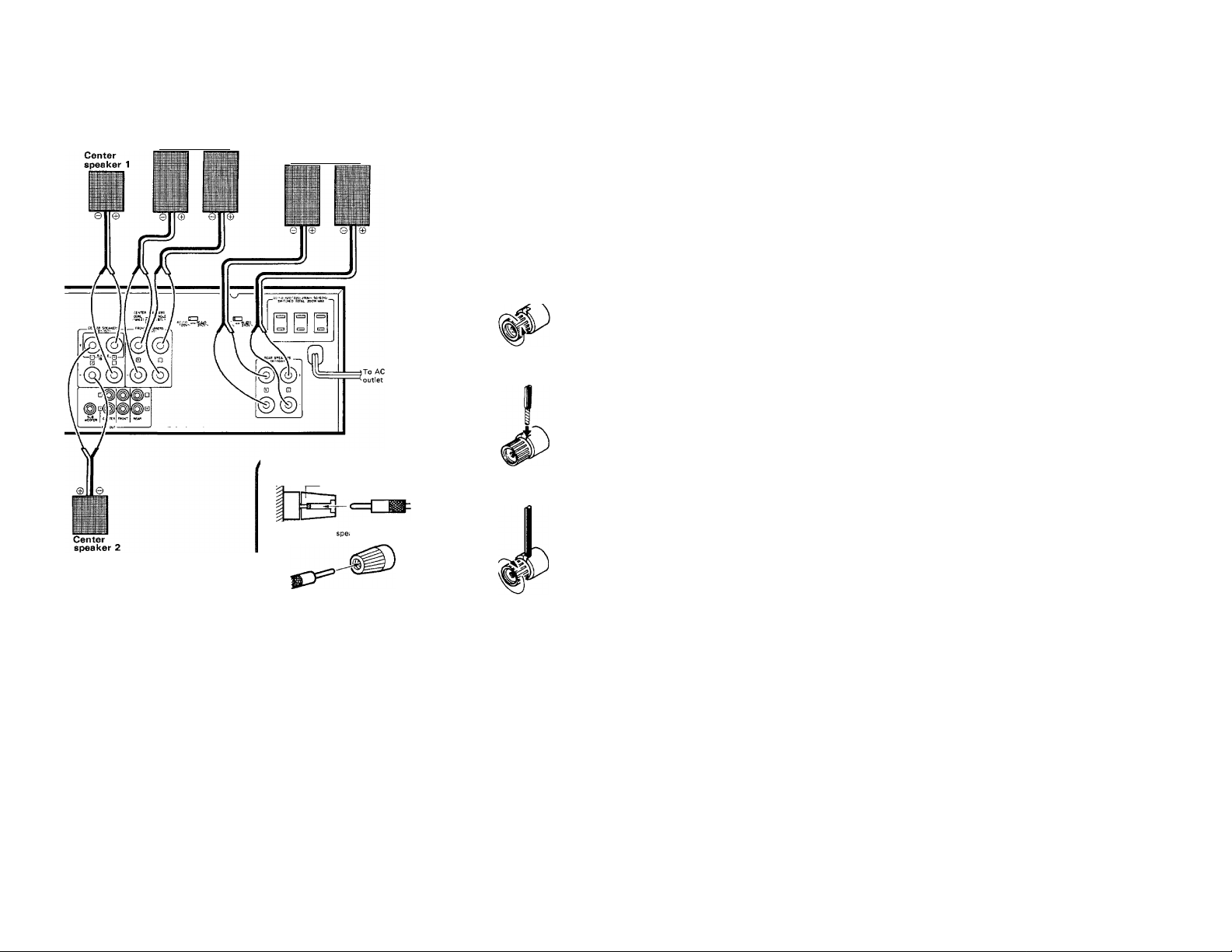
[Speaker connections
Front speaker system
(Right) (Left)
Connect the speakers as shown in the figure, paying
attention to the core wires not to come contact with
other jacks.
Rear speaker system
(Right) (Left)
Connection of banana plug
Tighten firmly
Cross section of the aker terminal
Process the cord.
Dating.
Twist conductors.
2 Turn counterclockwise
■ to loosen.
3 Fully insert the cable.
I
Turn clockwise to secure
^ the cable.
Please refer to the next page when one center speaker is connected.
Insert the banana plug securely, as shown.
Notes:
1. Connect all cords firmly, ¡f connections are loose there could be loss of sound or noise produced.
2. Do not connect up a power source which is larger than that indicated on the socket at the rear of the unit.
3. When plugging-and unplugging connection cords after connections are complete, be sure to first remove the power cord from the AC
outlet. Plugging/unplugging connection cords without removal of the power cord can cause malfunctions or damage to the unit.
Caution concerning speaker connections
1. Set the POWER switch to OFF before connection the speaker
cords.
2. After connecting the lead wires, verify that they do not come
into contact with other terminals.
3. Never short-circuit the (+) and (-) speaker cords.
4. Be sure not to inverse the left and right speaker connections
or the ( + ) and (—) terminal polarity. This will cause the acoustic
image of instruments to be unclear and the sound to be
unnatural.
KA-V9500 (En)
WARNINGI
Particular attention must be given to making good electrical
contact at the amplifier-output and speaker terminals.
Poor or loose connections can cause sparking or burning at
the terminals because of the very high power that the
amplifier can deliver.
Speaker impedance
Front speakers. Center speakers and rear speakers
Use speakers having an impedance of 6 to 16 ohms. In this
case, even if only one speaker has an impedance of less than
6 ohms, damage to the amplifier may occur.
Page 9
CENTER SPEAKERS switch
Up to two center speakers can be connected to this unit.
Set the CENTER SPEAKERS switch according to the number of the center speakers.
0 When one center speaker is connected: {the output
power is doubled compared to two-speaker operation)
Connect the speaker to the SINGLE (BTL) terminals.
0 When two center speakers are connected:
Center speaker 2 Center speaker 1
-o-W-o-
► Sound will not be output correctly if the switch is in the DUAL
(1 and 2) position.
► The center balance adjustment is not possible.
INPUT LEVEL control
If the reproduced sound is distorted,
adjust this control to suppress
distortion. For normal operation,
set to the center position.
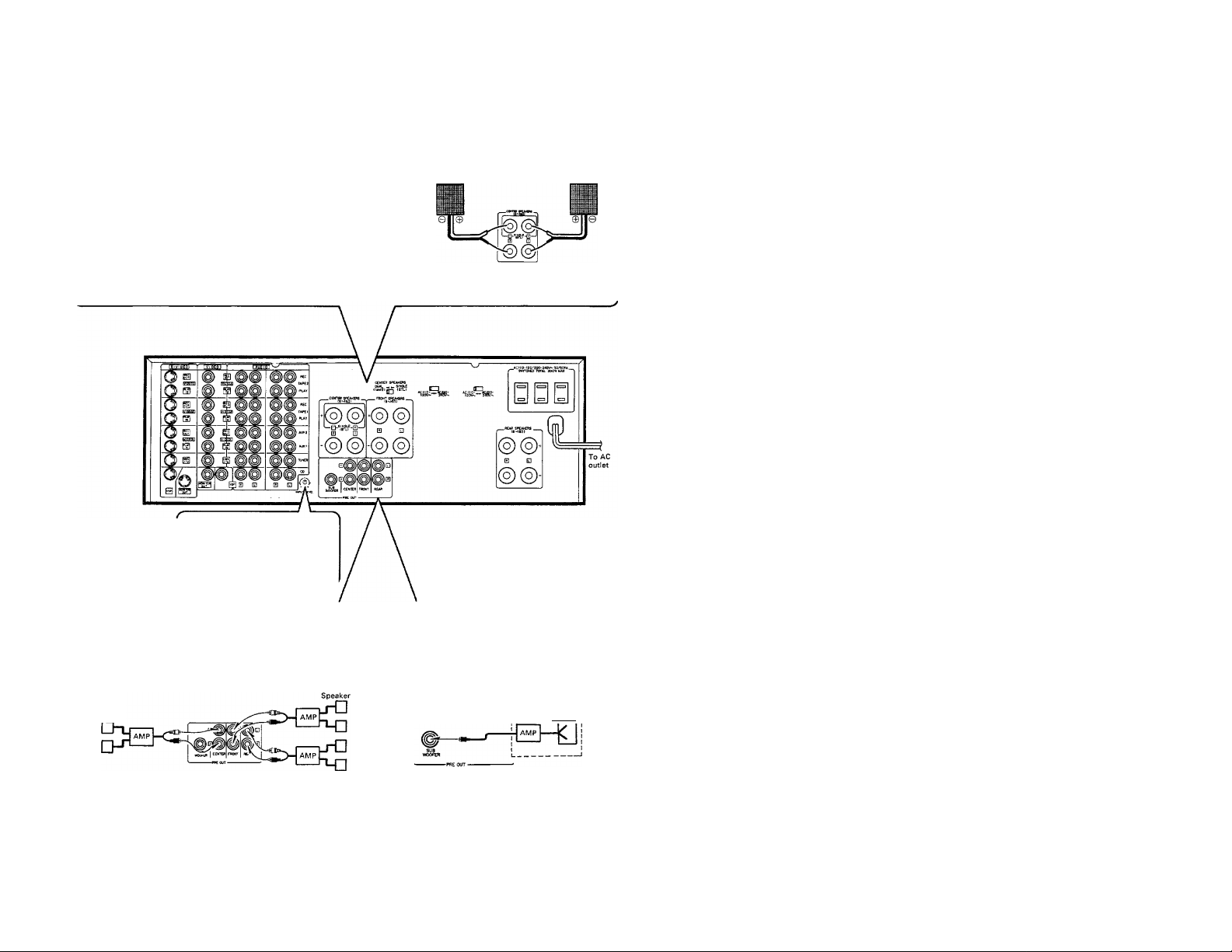
Connection of PRE OUT jacks
Sound will not be output from the speakers if they are connected directly to the PRE OUT jacks. The output from these jacks should
be connected to speakers with built-in amplifier or to exclusive amplifiers to which the speakers are connected.
0 Connection to CENTER, FRONT and REAR jacks
speaker
5) (o'
Center speaker
► Sound will not be output correctly if the switch is in the
SINGLE (BTL) position.
© Connection to SUB WOOFER jack
Speaker with built-in AMP
r Woofer I
» When the CENTER jacks are connected, be sure to set the CENTER
SPEAKERS switch to DUAL (1 and 2) position.
> Use these jacks if you want to listen to the speakers with larger volumes
or with different tones.
If you want to listen to richer bass sound, connect
the exclusive amplifier for the woofer to this jack,
and connect the woofer speaker to the amplifier.
KA-V9500 (En) 9
Page 10
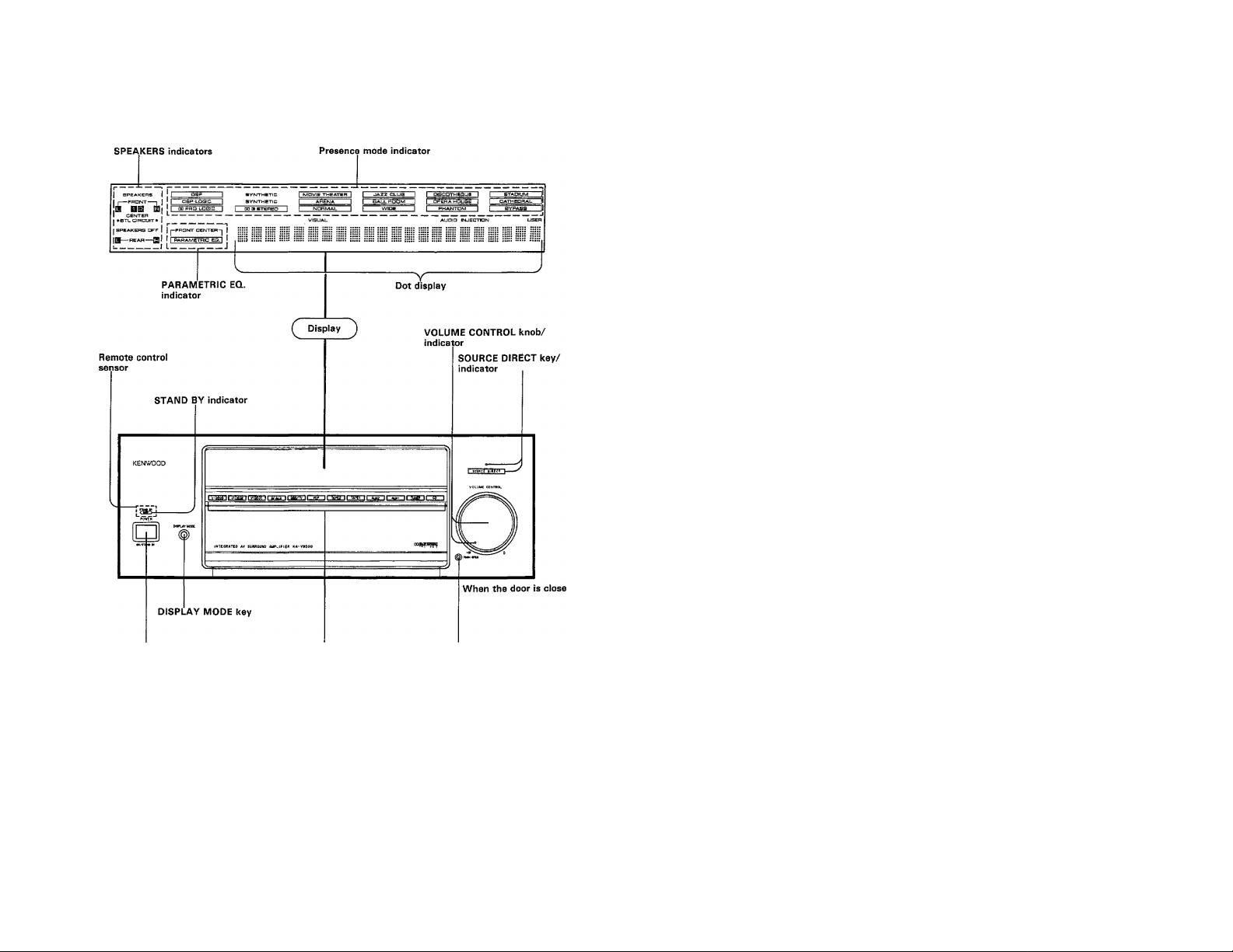
Controls and indicators
POWER key
Input selector keys
DISPLAY MODE key
Every press of this key switches the displayed contents as follows.
Indicators and dot display Dot display only -► OFF
t_______________________________________________I
► Both the indicators and dot display are displayed for about 5
seconds after another operation key is
10 KA-V9500 (En)
Door open key
STAND BY mode of POWER key
When the power cord of this system is plugged into an AC outlet,
the ST AN D BY indicator lights up regardless of the ON/OFF setting
of the POWER key. This indicates that a small amount of current
is being supplied to the unit to back up the memory contents. This
mode is referred to as the Stand By mode. While the STAND BY
indicator is lit the power of the system can be switched ON/OFF
from the remote control unit.
Page 11
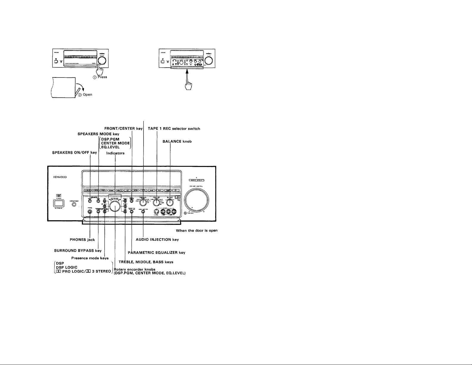
How to open the door
How to close the door
VIDEO 1 REC selector switch
KA-V9500 (En) 11
Page 12
Remote control operation
I Loading batteries
Replacing batteries
1. [f the TRANSMIT indicator does not light even when the
operation key is pressed, the batteries are exhausted.
Replace the batteries. We recommend that the alkaline batter
ies (LR03/AM-4) which have longer service life be used.
2. The programmed contents are not immediately lost when the
batteries are removed for replacement. However, they could be
lost if the unit is left without batteries for more than 3 minutes.
In such a case, the programming should be performed again.
The function signals of the non-learning, or fixed keys are not
lost even in this case.
Note:
Avoid using old and new batteries together, as this may cause
corrosion.
I Operating range of the remote
control unit
The normal operating range may change depending on
temperature, humidity, and other environmental con
ditions, but it is roughly specified as shown in the
figure.
12 KA-V9500 (En)
Model name: RC-V9500L
Transmission system:
Infared pulse system
Notes:
1. if two or more remote control operation keys are to be pressed
successively, press each key securely and leave an interval of
more than 1 second between presses.
Pressing a key immediately after pressing another key may
cause malfunction.
2. Malfunction may occur in case direct sunlight or the light of a
high-frequency lighting fluorescent lamp enters the remote
control light receptor. In such a case, change the installation
position of the unit so that the malfunction does not occur.
Page 13
Z
Û)
3
Ф
(A
O
■-+1
O
O
3
r+
O
CO
Page 14
Remote control operation
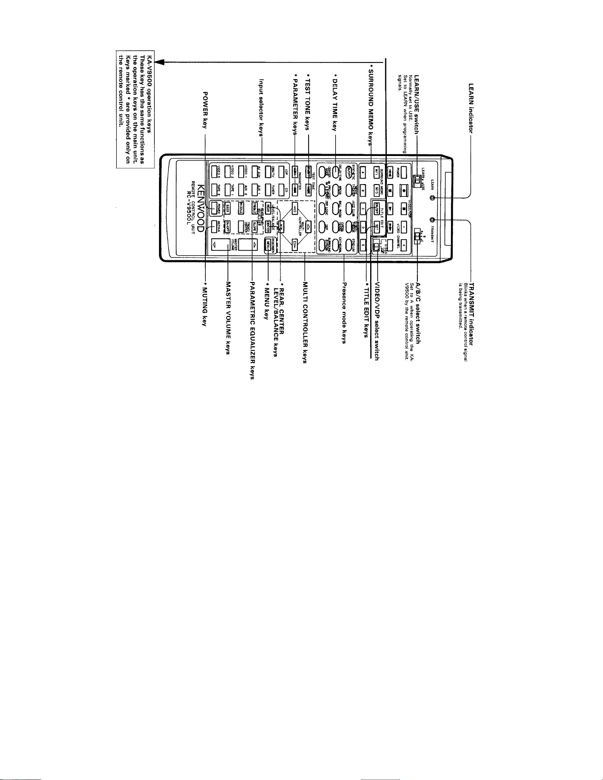
■ Using the unit as a programmable remote control unit
The remote control functions of other audio and video components can be programmed (stored) in this unit. For
the programming operation, refer to page 17.
Set to USE.
The programmable keys
(learning keys) vary depend
ing on the position of the
A/B/C select switch.
In "A" position;
The remote contro! functions of a
video component can be pro
grammed (stored) under the opera
tions keys in this section.
In "B" or "C" position:
All keys are usable as the program
ming keys (learning keys). Program
(Store) the remote control functions of
any other audio or video component
under them.
________
L EARN @
ЙШ-
□□ Ш сю [Ю Ю
ШВЩ1 '
'■ \/(Г\ГЛ ЛиАРиЫП
VIDEO CHANNEL
11ш
XJ3 сю EU СЮ ED
t^YTi^ ^ пош сАттт
^ZCL№ RADIUM
gPLWK ^ DSP ^
-A/B/C select switch
-VIDEO/VDP keys
-VIDEO/VDP select switch
When both a video cassette recorder
and an LD player is used, set this
switch to select VIDEO (video cassette
recorder) or VDP (LD player). This
switch is not valid when the A/B/C
switch is in the "C" position.
U KA-V9500 (En)
KENWOOD
For your convenience, it is
recommended to write the
programmed (stored) func
tions on the provided entry
sheets. Use a oil-ink felt pen,
pencil, etc., for writing. For
erasing, use an ordinary eras
er and rub with a strong
force.
Page 15

I How to program the remote control functions of other components
under the ^'learning" keys of this remote control unit
1 Set the LEARIM/USE switch to LEARIM.
I Set the A/B/C select switch to the desired
* position.
[ Place the remote control unit of another com-
* ponent with this remote control unit (RC-
V9500L) so that their heads (signal transmit
ters) face each other.
Press the learning key of RC-V9500L under
4
which you want to program the function
signal.
ifDTfffaOfw' 0
lD'iQ|[ikK)€,0.: Q;Q^^G0CSi 1 :
Qi|'B dgSiCi’s'rajflo-o-at
• LEARN indicator will light up,
[ Within 30 seconds after pressing the key
^ above, press and hold the key of the other
remote control unit which contains the func
tion to be programmed (stored).
Press and hold
ulaDWflmo 0 1 □¡'□T
BEiimioii 0
JB № QwcHjl :8'Si a ca
• The LEARN indicator changes from steady lighting to blinking,
indicating that the function signal is being programmed.
j When the LEARIM indicator goes off after
blinking twice, release your finger from the
key of the other remote control unit
Signal is programmed under this key.
> Be sure to hold the key of the other remote control unit
depressed until the LEARN indicator goes out.
» The programming is completed when the LEARN indicator
goes out after two times of blinking.
I To program another function signal under another key, repeat
steps 4 to 6 above.
KA-V9500 (En) 15
Page 16

Remote control operation
■ To check the programmed
(stored) contents
1 Set the LEARN/USE switch to USE.
LEARN« >USE
_OQ
\ Press the key you want to check the function
■ of.
> Check to see if the intended function is
^ activated.
I To change the programmed
(stored) contents
Re-start the programming (storing) operation.
I The previously-programmed contents are cleared automatically
and replaced by the newly-programmed contents.
■ To perform normal remote con
trol operation
J Set the LEARN/USE switch to USE.
LEARN. «USE
Press the "learning" key under which the
required function signal has been pro
grammed.
• The TRANSMIT indicator blinks and the remote control
function is performed.
■ To clear the whole of the pro
grammed (saved) contents
<-----------------------------------------------------------------------V
1 Set the LEARN/USE switch to LEARN.
LEARN« «USE
2 Set the A/B/C switch to "C".
□ml
3 Press any key.
• The LEARN indicator lights up.
I Remove the battery case cover on the rear of
^ the remote control unit.
[ Press the Reset key inside the battery case
' with a ball-point pen tip, etc.
> All of the previously-programmed contents are cleared simulta
neously and the remote control unit is reset to the initial
condition.
Reset Key
Almost all of the remote control systems used with other AV components use the same infrared system as this unit. This means that this
unit is capable of programming the functions of almost all remote-controllable components, Before programming, please read carefully the
instruction manuals of other AV components as well as this Instruction Manual.
Notes:
1. If the optical output power of the other remote control unit is too large, programming could fail. In such a case, place the remote control
unit at a greater distance from this remote control unit.
2. If both the LEARN indicator and TRANSMIT indicator blink simultaneously, either the key is not a "learning" key which can be used for
programming or the current programming is incomplete. In such cases, program the function again under a "learning" key.
3. Programming is also impossible if the other remote control unit uses a signal format other than the infrared system, if it uses a special signal
modulation format, or if the storage capacity of this unit has become full.
4. 30 seconds after a "learning" key is pressed, the LEARN indicator goes from on to off (extinguished). As programmming is impossible while
the indicator is off, press the "learning" key again to light the indicator.
5. If more than one "learning" key is pressed, the function signal is programmed under the last pressed key.
6. Never attempt to program (store) the remote control functions of appliances other than AV components, such as air condition
ers.
16 KA-V9500 (En)
Page 17

On-screen character display
The on-screen character display appears on the monitor TV screen when specific operations are performed. The
information on the present setup various modes can be checked by pressing the MENU key on the remote control
unit. Whether the on-screen display is displayed or not can also be set.
H Checking the modes [ Remote control unit only I
Example: In case DSP.LOGIC and Parametric Equalizer is ON
1 Press the MENU key.
raj
u
^ • The TV screen changes to the condition shown in Fig. (A)
The display which appears when the MENU key is pressed changes according to the mode of the unit.
2 Press the MENU key more again.
ioNSCRE^l
• Every time the key is pressed, the display changes from Fig.
(A) to Fig. (K) repeatedly in cycle. ^
Notes:
1. On-screen displays shown in Fig. (A) and Fig. (K) remains for about 1.5 second. Other displays will not change until the MENU key is
pressed,
2. If the above cycle is terminated with "INFORMATION OFF" display, the on-screen character display will not appear in later operations.
3. If it is required to have on-screen character display afterward, terminate the cycle with "INFORMATION ON".
KA-V9500(En) 17
Page 18

Playing back an audio source
I Basic operation procedure
18 KA-V9500 (En)
Page 19

To mute sound temporarily I Remote control unit only I
I Press again to resume the previous volume.
SOURCE DIRECT key
When this key is pressed, the indicator lights up and the source
selected by the input selector key can be reproduced with a higher
sound quality.
--------Lights u
• The unit enters the bypass mode. In this mode, the input
audio signal does not pass through the parametric equalizer
and balance adjustment circuits, so the tone and balance
adjustments are not effective.
To cancel SOURCE DIRECT function:
Press again.
» The SOURCE DIRECT function is also canceled automati
cally when any Presence mode Is selected or SURROUND
BYPASS mode is set to ON.
o
----------
I SOURCE^IBECT^
Goes off
SOURCE DIRECT key
■ How to listen through headphones
Insert the headphone plug into the PHONES
■ jack.
If the reproduced sound is distorted, adjust the INPUT LEVEL
control on the rear panel to suppress distortion.
INPUT LEVEL knob
► The [SPEAKERS OFF| indicator lights up.
3 Adjust the volume.
VOLUME CONTROL
KA-V9500 (En) 19
Page 20

Recording an audio source
I How to record sound on cassette
decks connected to the TAPE 1
and TAPE 2 jacks
I How to dub sound from cassette
deck 1 (connected to TAPE 1
jacks) to cassette deck 2 (con
nected to TAPE 2 jacks)
1 Set the TAPE 1 REC switch to SOURCE. | 1 the TAPE 1 REC switch to SOURCE.
TAPE1 REE
SOURCE
TAPE AUX 2
\AUX1
I) TUNER
7co
2 Select the recording source.
3 Start recording on the cassette deck(s).
• Simultaneous recording on TAPE 1 and TAPE 2 is possible.
2 Press the TAPE 1 input selector key.
3 Start recording on cassette deck 2.
Start playing cassette deck 1.
TAPE1 REC
SOURCE
TAPE AUX 2
JiAUXI
llTUNER
yCD
I TAF^2 I I TA^I 1 j AUX2 I
I How to dub sound from cassette deck 2 (connected to TAPE 2 jacks)
to cassette deck 1 (connected to TAPE 1 jacks)
Dubbing while listening to another source
Select the source to be listened to.
1 *rvipÈòg N rn»»JuK iras/Tvli 11 rr"TI^rn t iiwr~11 ¿uirt \i 1 i|
Dubbing while listening to the sound of cassett^
deck 2
1 Set the TAPE 1 REC switch to SOURCE.
TAPE 1 REC
SOURCE
TAPE 2^.;^:^AUX 2
^ IJtumer
2 Set the TAPE 1 REC switch to TAPE 2.
TAPE 1 REC
SOURCE
TAPE Z,^^:^AUX 2
/f° ^^AUX1
^ ^TUNER
2 Press the TAPE 2 input selector key.
1 VDP 1 1 TAPE2 1 PtAPeTI
b
3 Start recording on cassette deck 1.
4 Start playing cassette deck 2.
__________________
The signal dubbed, or recorded on the cassette decks cannot be processed by the Surround or PARAMETRIC EQUALIZER control circuitry.
20 KA-V9500 (En)
___
_____________________
3 Start recording on cassette deck 1.
ZL Start playing cassette deck 2.
J
Page 21

Recording an audio source while listening to another
The TAPE 1 REC switch of this unit allows to record a sound on cassette deck 1 independently from the source
being listened to.
I Independent recording on cas
sette deck 1
Input selector keys
TV screen when the TAPE 1 REC switch is set to CD
Note;
When TAPE 2 is selected with the TAPE 1 REC switch while the
TAPE 1 input selector key is selected, characters "TAPE 1" on the
display will blink. In this case, press an input key other than TAPE
1.
KA-V9500(En) 21
Page 22

Playing back a video source
[ How to play a video source
Switch ON the power of the monitor TV
1
connected to the MONITOR OUT jacks.
2 Select the video source to be viewed.
r VIDEOS if VIDE02 I I VIDEOt I j AVAUX I I DBS^ 1 I VDP \
O o'
1
1 a w s-s-
f OffiE»!
3 Start playing the selected video component.
• The picture is reproduced on the monitor TV screen, and
the sound is reproduced through the speakers.
4 Adjust the volume.
VOLUME CONTROL
* The audio operation procedure is the same !
scribed in "Playing back an audio source".
Note:
The characters "VIDEO 1" in the display window will blink if the
VIDEO 1 is selected with the input selector key when the VIDEO
1 REG switch is set to either VIDEO 2 or VIDEO 3. In this case,
set the VIDEO 1 REG switch to SOURCE.
; that de-
_______
AUDIO INJECTIO^
J key
■ Audio Injection operation
This feature allows to replace the audio of the video
source being played back with the audio of another
source.
© Play a video source.
© Press the AUDIO INJECTION key.
AUDIO INJECTION
© Select the source to replace the audio.
/
To cancel audio injection
Press the AUDIO INJECTION key again.
AUDIO INJECTION
22 KA-V9500 (En)
TV screen when the TUNER audio is selected for
Audio Injection
> The Audio Injection function is also canceled when the POWER
is switched OFF.
Page 23

Recording a video source
I Video/audio recording on video
deck(s) 1/2/3
Set the VIDEO 1 REC switch to SOURCE.
VÌDEO 1 REC
SOURCE
VIDEO 2
VIDEO 3//''^^^DBS/TV
KSKVOOO
2 Select the source to be recorded.
O "0
3 Start recording on VCR 1.
» The selected source being recorded can be monitored on
the monitor TV during recording.
■ Dubbing from video deck 1 to video deck 2 or 3
r
"I Set the VIDEO 1 REC switch to SOURCE.
VIDEO 1 REC
SOURCE
VIDEO AUX
VIDEO i/y^^^OBS/TV
^ 6 -f
VIDEO 1
¥wm
r
=tEC switch
2 Press the VIDEO 1 input selector key.
3 Put video deck 2 or 3 in the record mode.
Z|. Put video deck 1 in the play mode.
• The video and audio of video deck 1 can be monitored during dubbing.
Í VIDE03 II VIDEQ2 I I VIOEOt 11 AVAUX I t DBS/TV I { VDP I
KA-V9500 (En) 23
Page 24

Recording a video source
■ Dubbing from video deck 2 to
video deck 3
1 Set the VIDEO 1 REC switch to SOURCE.
VIDEO 1 REC
SOURCE
VIDEO
VIDEO z/f ® ’^DBS/TV
2 Press the VIDEO 2 input selector key.
I VIDEOS I I VlpPQ2 } i yiDEOl \ I AVaUX I
3 Put video deck 3 in the record mode.
Put video deck 2 in the play mode.
)|VDP
■ Dubbing from video deck 3 to
video deck 2
^
.......................
^
1 Set the VIDEO 1 REC switch to SOURCE.
2 Press the VIDEO 3 input selector key.
3 Put video deck 2 in the record mode.
^ Put video deck 3 in the play mode.
I Dubbing from video deck 2 or 3 to video deck 1
To monitor the video and audio during dubbing
Set the VIDEO 1 REC switch to SOURCE.
VIDEO 1 REC
SOURCE
VIDEO
VIDEO 3/V^°"^0BS/TV
1 1 wjeonryiota! rf^Sci' 11 «/AUK~11 i)B5/Tv 11 vap iI~)»iti insni »un li hw» il i |
O”
O Press the VIDEO 2 or VIDEO 3 input selector
^ key.
1 VIDEOS II VIDE02 iJ VIDEOl tl AVAUX 1
To listen to another source during dubbing ^
^ Select the source to be listened to.
O Set the VIDEO 1 REC switch to VIDEO 2 or
^ VIDEO 3.
'^
VIDE01 REC
SOURCE
VIDEO
VIDEO 3J/^® \\DBS;/TV
Ì Vioeos II VIPEQZ I I Vi PEPI II AVflUX 1
VIDEO 1 REC
SOURCE
VIDEO AUX
VIDEO 3/5 ^^DBS/TV
b
b
3 Put video deck 1 in the record mode.
¿L Put video deck 2 or 3 in the play mode.
V7
24 KA-V9500 CEn)
3 Put video deck 1 in the record mode.
£L Put video deck 2 or 3 in the play mode.
J
Page 25

Independent audio/video recording from source being played
The VIDEO 1 REC switch of this unit allows to record the audio/video signals onto the VCR 1 independently from
the source selected for playback.
■ How to record audio/video on VCR 1 independently from the source being played
^ ..................................................................................
^ Select the source to be played back.
Lim;J LmasJ |ди;' | гжго LPsyTv i'~?wgri Г~^13
I Select the source to be recorded onto the
■VCR 1.
VIDEO 1 REC
SOURCE
VtOEO
VIDEO 3/У^ ° ’'*^DBS/TV
I If the switch is set to SOURCE, the source selected by the
input selector key will be recorded.
3 Start recording on the VCR 1.
» You can listen to the source selected by the input selector
key, while the VCR 1 records the source selected by the
Vìdeo i rec switch.
Example of on-screen character display
This unit incorporates the model name preset function {see page
40). This function allows to store the model names of other system
components so that you can record them by identifying them with
the model names.
When the DBS/TV input is recorded to the VIDEO 1 (KV-D958S)
output, while the tuner (KT-5020) broadcast input is played.
Input selector keys
Note;
If the VIDE01 REC switch is set to VIDE02 or VIDEOS while
VIDE01 has been selected by the input selector keys, characters
"VIDE01" on the display blinks, in this case, select other source
than VIDE01 by the input selector keys and try again.
(Remote
control unit)
INPUT
REC OUT VIDEO 1
DBS/TV KV-D958S
KT-5020
KA-V9500 (En) 25
Page 26

Parametric equalizer operation
Parametric equalizer
The parametric equalizer is ap equalizer system which can adjust
the center frequency and curve (Q) slope of each frequency band.
With this unit, the center frequency of the BASS band is fixed at
100 Hz and that of the TREBLE band is fixed at 1 0 kHz, but that
of the MIDDLE band can be selected from 250 Hz, 400 Hz, 630
Hz, 1.0 kHz, 1.6 kHz, 2.5 kHz and 4.0 kHz. The slope of the curve
(Q) can be selected between WIDE and NARROW for each of the
BASS, MIDDLE and TREBLE bands. In addition, these equalizer
setting can be given independently to the FRONT and CENTER
speakers.
I Preparation for creation of equalizer curve
1 Press the PARAMETRIC EQUALIZER key.
WRAMETRIC KVIlLritl
EQUALiZER lON/OFFl
Lights up
- L
(Remote
\—h
^
____
f (Amplifier)
n
t The EQ LEVEL indicator is displayed.
2 Select the FRONT or CENTER speakers.
control unit)
When FRONT is selected
Display : DSP LOGIC mode
When CENTER is selected
TRE,
--------
---
T R E «
NARROW
• Every press alternates FRONT —*■ CENTER.
• The equalizer effect can be applied independently to the front and center speakers. However, in the DSP mode, the equalizer effect
cannot be applied to the center speaker(s).
26 KA-V9500 (En)
Page 27

I Adjusting the tone
Bass frequency adjustment
0 Press the BASS key.
(Amplifier)
0 Adjust the level.
(Amplifier)
• The adjustment range is within ±10 dB.
0 Select the slope of the curve. (Remote control unit)
Every press alternates WIDE and NARROW.
Middle frequency adjustment
0 Press the MIDDLE key.
PARAMETRIC
EQUALIZER
(Amplifier)
FFm£l (SL^
0 Select the center frequency.
MIDDLE
/Rûmnfa — “
I j (Remote
~f^
\
____
( controller)
BASS, MIDDLE, TREBLE keys
FRONT/CENTER key
i IS'
EQ LEVEL
adjustment PARAMETRIC EQUALIZER key
rotary encorder
Treble frequency adjustment
0 Press the TREBLE key.
"¿T o
■FRONT/CENTER
key
IN/OFF key
________
j (Remote
{ controller)
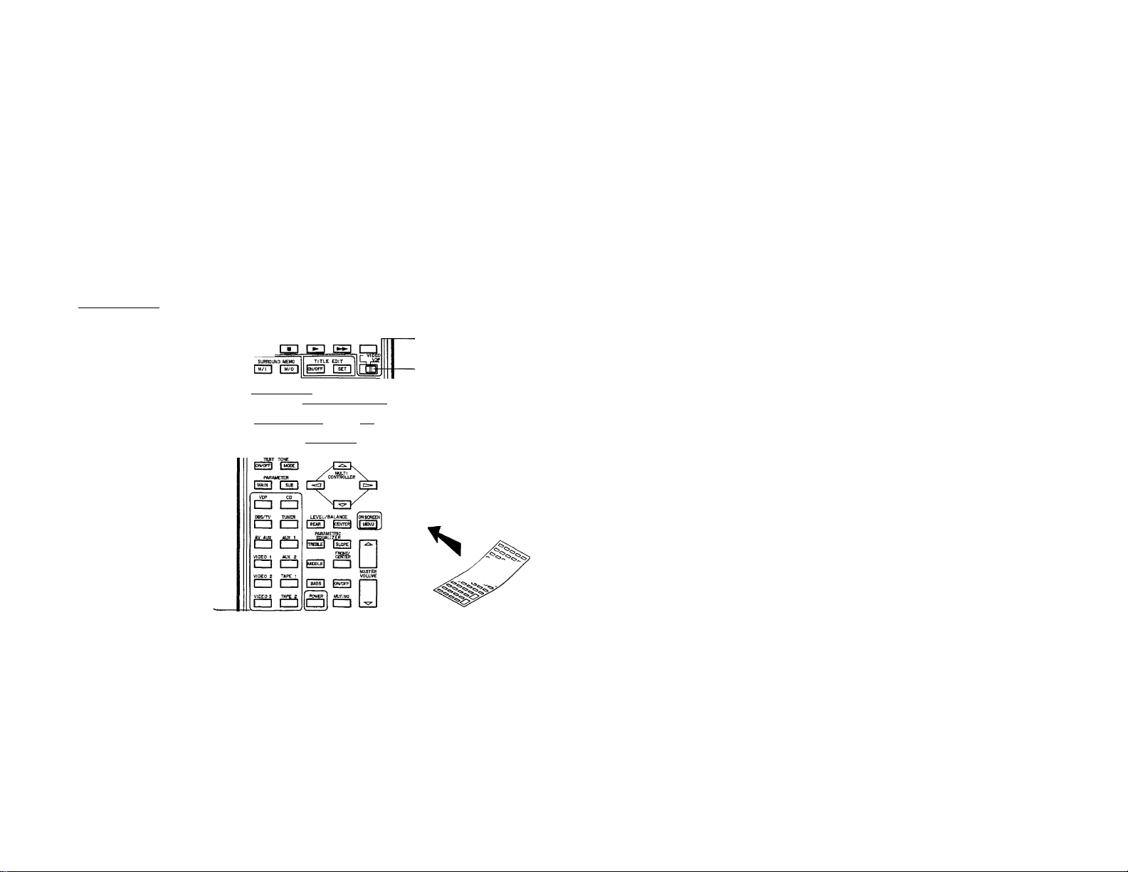
-''=0
iRismnt» ^ ^
(Remote
controller)
• Every time the MIDDLE key is pressed, the center frequency
is switched to 250 Hz, 400 Hz, 630 Hz, 1.0 kHz, 1.6 kHz,
2.5 kHz and 4.0 kHz.
0 Adjust the level.
• The adjustment range is within ± 1 0 dB.
0 Select the slope of the curve. (Remote control unit)
(Amplifier) ^
(Amplifier)
(Amplifier)
0 Adjust the level.
• The adjustment range is within ±10 dB.
0 Select the slope of the curve. (Remote control unit)
y V.
f (Remote
controller)
KA-V9500 (En) 27
Page 28

Presence feature
Presence effects
Why do we feel the sounds in movie theaters, concert halls and stadiums so powerful and live? Because the sound reaches us not only
from the front but from all other directions surrounding us. To reproduce this ambience as close as possible to the reality, this unit incorporates
three types of Surround decoder circuits for use with different types of music sources. Every presence mode provided by these circuits
uses a dedicated DSP (Digital Signal Processor) to allow creation of an amazing acoustic field without compromising the sound quality.
To make full use of the Presence effects, read the following instructions carefully and perform equipment installation and adjustments that
suit your individual listening room.
|(^ Digital DOLBY PRO LOGIC Surround!
Video and LD software packages marked with ОП!!
in the recording. The Digital DOLBY PRO LOGIC Surround decoder bujlt into this unit makes it possible to enjoy such software packages
with the same audio effects as in movie theaters.
• Set the center speaker mode according to the speaker layout (see page 29).
\(^ Digital DOLBY 3 STEREO I
When the right and left speakers are installed away from each other, the center sound image becomes fade. DOLBY 3 STEREO mode gives
the directivity effect to enhance the center sound image. (Refer to page 29.)
|(^ DSP Presence!
An advanced digital signal processing adds to the enjoyment of stereo audio sources such as CD, TAPE and TUNER. This unit creates the
DSP Presence sound fields (hall tones) of these sources by means of the 1 8-bit A/D converters which perform high-level conversion of analog
signals into digital signals, as well as of the computer simulation and dedicated DSP (Digital Signal Processor) which create early reflection
and reverberation sound signals. By combining these signals, the parameters such as the room sizes, walls and listening positions can be
set so that realistic feeling proper to live performances can be reproduced In the living rooms of households.
• This unit provides ten preset DSP Presence sound-field patterns. (See page 33.)
• it is also possible to create the user's own sound fields by combining parameters. (See page 34.)
• Set the SPEAKERS MODE key according to your speaker layout (See page 29.}
|@ DSP.LOGIC Presencej
Video and LD software packages marked with OOi»
in the recording. The DSP LOGIC Surround decoder built into this unit makes It possible to enjoy such software packages with the same
audio effects as in movie theaters. The DSP LOGIC Surround decoder creates the same realistic feeling as the powerful sound surrounding
us in movie theaters, concert ha!Is_a_n_d stadiums by adding early reflection sound and reverberation sound signals to the output signal from .
the directivity enhancer circuit.
• This unit provides eight preset DSP LOGIC Presence sound-field patterns. [See page 33.)
• It is also possible to create the user's own sound fields by combining parameters. (See page 34.)
• Set the SPEAKERSJMODE key according to your speaker layout. (See page 29.)
The information set in the above mode can be stored in the surround information memory. (Refer to page 38.)
] incorporate the same Dolby Surround information as "Dolby Stereo" movies .
incorporate the same Dolby Surround information as "Dolby Stereo” movies
Manufactured under license from Dolby Laboratories Licensing
Corporation. Additionally licensed under one or more of the
following patents: U.S. numbers 3,632,886. 3,746,792 and
3,959,590; Canadian numbers 1,004,603 and 1,037,877,
"Dolby" and the double - D symbol
Laboratories Licensing Corporation.
DD are trademarks of Dolby
28 КА-У9Б00 IEn>
Page 29

■ Speaker layouts
It is possible to use either one of two center speakers.
/•
Standard layout
Front Center speakers Front
□eTct'"
SP SP
SPEAKERS
I
-----
FRONT
m am à
----------
© DOLBY PRO LOGIC mode
Set the center mode according to the center speakers used.
... NORMAL (when compact speakers are used)
1
... WIDE (when medium-sized or larger speakers are used)
© DSP and DSP.LOGIC modes
4
In case rear (Surround) speakers are not used
I----FRONT-1
a as É
In case center speakers are not used
Front
0
SP
Rear Rear
In case only two speakers are used
""o,
Front
1 TV 1 SP
—FRONT—^
01
--
REAR-gl
SP
Press repeatedly until the display becomes a
shown on the left.
I Select the desired sound-field pattern (see page 36).
© DOLBY 3 STEREO mode
Set the center mode according to the center speakers used.
... NORMAL (when compact speakers are used)
... WIDE (when medium-sized or larger speakers are used)
© DSP and DSP.LOGIC modes
Press repeatedly until the display becomes a
shown on the left.
I Select the desired sound-field pattern (see page 36).
© DOLBY PRO LOGIC mode
Set the center mode to PHANTOM.
... PHANTOM
© DSP and DSP.LOGIC modes
Press repeatedly until the display becomes as
shown on the left.
* Select the desired sound-field pattern (see page 36).
DSP mode
Press repeatedly until the display becomes a
shown on the left.
• Select the desired sound-field pattern (see page 36).
• The Dolby Surround play is not possible with this layout.
KA-V9500 (En) 29
Page 30

DOLBY PRO LOGIC, 3 STEREO adjustments (Remote control unit)
■ Adjustments in NORMAL or WIDE mode (in dolby pro logic or 3 stereo mode)
Preparation: Set the parametric equalizer to OFF.
Enter the DOLBY PRO LOGIC or 3 STEREO
* mode.
» The DOLBY PRO LOGIC mode and 3 STEREO mode are
alternated every time the key is pressed.
[ Select the NORMAL or WIDE mode.
• Every time the CENTER MODE key
is pressed, the center modes of the
DOLBY PRO LOGIC mode are
svAiitched in the following order;
NORMAL ^ WIDE PHANTOM
t
________________
The center modes of the 3 STE
REO mode are switched alternate
ly as follows:
NORMAL WIDE
[ Turn the test tone ON.
> Press from your listening position.
Press the TEST TONE MODE key.
4
I Every time the key is pressed, noise-like test tone is output
from different speakers in order of Left Center -► Right
-►Rear (Rear speakers are not used in 3 STEREO mode).
Holding the key depressed switches the tejst tone m.odes
every 2 seconds.
[ Adjust the balance between all speakers so ' that their volumes are the same.
LEVEL/BALANCE A k I
j REAfT) /w(i™OLLER^\ !
'
------------
1 I
----------------
• When two center speakers are used, adjust the left and right
balance of them.
• The REAR BALANCE controls are adjusted to make the
volume levels from the right and left rear speakers equal.
• The rear speakers are not used in the 3 STEREO mode. In
this case, therefore, adjust so that the volumes from the
three front speakers are equal.
TEST TONE
TEST TONE
> Volume
-----------
Balance
^ K Small
--------
Left
0 Terminate the adjustment.
• Press the TEST TONE ON/OFF key to OFF.
»-Right
Large
I
TV screen during adjustment:
In DOLBY PRO LOGIC, NORMAL or WIDE mode:
DOLBYPRO LOGIC NORMAL
■ ■ ■ ■
-lOdB -lOdB
■
C R
111! nil
-lOdB -lOdB
TEST
S
(REAR) ■
In Dolby 3 Stereo, Normal or Wide mode:
DOLBY 3 STEREO NORMAL
L C R
-lOdB -lOdB
TEST
—speaker from
which sound
is output
“Speaker from
which sound
is output
3D KA-V9SOO (En)
Page 31

■ Adjustments in PHAIMTOM mode (in dolby pro logic mode only)
Preparation: Set the parametric equalizer to OFF.
1 Enter the DOLBY PRO LOGIC mode.
• The DOLBY PRO LOGIC mode and 3 STEREO mode are
alternated every time the key is pressed.
® pRoiogc
m SSTE^
' Select the PHAIMTOM mode.
t Every press of the key switches
NORMAL -+ WIDE PHANTOM
t
_ _ _ _ _ _ _ _ _ __ _ _ _ _ _ _ _
[ Turn the test tone ON.
I Press from your listening position.
4 Press the TEST TONE MODE key.
► Every time the key is pressed, a notse-like test tone is output
alternately from the front and rear speakers. Holding the key
depressed switches the test tone modes every 2 seconds.
! Adjust so that the volumes from the four
* speakers are almost equal.
LEVEL/BALAfKE
TEST TONE
I MOt£ I
TEST TONE
Large
CENTER MODE key-
TEST TONE keys-
I
TV screen during adjustment:
In DOLBY PRO LOGIC, PHANTOM mode:
DOLBY PRO LOGIC PHANTOM
L
■
m i
-lOdB
■
TEST
s
(REAR)
R
■
MM —
-lOdB
■
□□ PRO-LOGIC/
OD 3 STEREO key
MULTI CONTROLLER
keys
LEVEL/BALANCE keys
(REAR}
“Speaker from
which sound
is output
Left
-----------
► The REAR BALANCE controls are adjusted to make the
volume levels from the right and left rear speakers equal.
Balance
--------
►Right
Small
0 Terminate the adjustment.
^ • Press the TEST TONE ON/OFE key to OFF.________________
■ Adjustments in input balance
^^
The input balance is adjusted automatically.
"This unit features an automatic input balance control, eliminating
the need to adjust L/R input balance for different sources and
optimizing performance of the DOLBY PRO LOGIC Surround/
DOLBY 3 STEREO decoding by minimizing crosstalk."
Display:
TEST TONE FRO.HT
KA-V9500 (En) 31
Page 32

Playback with DOLBY PRO LOGIC or 3 STEREO
Before start playback, adjust the unit referring to the
procedures on pages 30 or 31.
32
KA-V9500 (En)
To cancel
Press the BYPASS key.
%
{Remote
control unit)
Be sure to set the Bypass mode whenever the Surround effects
____________________
Note:
The output from the CENTER SPEAKERS terminals or PRE OUT
CENTER jack on the rear panel is output only in the NORMAL and
WIDE modes of the DOLBY PRO LOGIC mode and the DOLBY 3
STEREO mode.
y
Page 33

DSP Presence
DSP (Digital Signal Processor)
The DSP allows to synthesize the early reflection and reverberation sound signals in order to create various sound-field effects without
compromising the sound quality of music sources.
This unit provides two DSP Presence modes; the DSP mode and the DSP.LOGIC mode.
DSP mode:
Provides eight sound field patterns as well as the SYNTHETIC MOVIE THEATER and SYNTHETIC ARENA
modes for use with monaural sources.
DSP.LOGIC mode:
Applies a directivity enhancement to the DSP mode to enable even better acoustic image positioning. Eight
sound field patterns are available.
[Preset sound field effects using DSP|
This unit incorporates 10 kinds of preset sound field patterns, so that various sound field effects can be enjoyed by selecting a preset pattern
according to the music source. The main and sub parameters and parametric equalizers are adjusted according to the sound field effect
patters.
In addition, it is also possible to obtain desired sound field patterns by adjusting the parameters forming them. Refer to page 34 for the
parameters.
I
Kinds and effects of preset sound field patterns |
Select an optimum sound pattern according to the music source.
Sound Field Pattern
MOVIE THEATER Sound field of a high-quality movie theater.
JAZZ CLUB
DISCOTHEQUE
STADIUM
ARENA
BALL ROOM
OPERA HOUSE
CATHEDRAL
SYNTHETIC MOVIETHEATER
SYNTHETIC ARENA
Early reflection sound is concentrated in the period from 20 to 70 millisec. A realistic and live
sound field.
Early reflection sound is concentrated in a short period, providing a concentrated feeling of energy
rather than expansion.
The interval of early reflection sound is widely dispersed. A sound field like the sound from the
PA equipment in an outdoor stadium.
Sound field of a wide and deep ha II, where the interval of early reflection sound is widely dispersed.
The hall size may accommodate an audience of around 2500 people.
A hall with a medium size accommodating an audience of around 1300.
Sound field of an opera house, where the level of early reflection sound is high and the
reverberation after it attenuates slowly.
Sound field of a large cathedral, whether the early reflection sound has a long delay and the
reverberation after it lasts for a long period.
When playing a monaural source, use them in the DSP mode.
These patterns cannot be used in the DSP.LOGIC mode.
Effect
KA-V9500 (En) 33
Page 34

DSP Presence
I DSP parameters]
In addition to the selection of preset sound field patterns, the Surround effect can also be enjoyed by adjusting the following parameters
to obtain a sound field that matches your taste.
1. Main parameters
(T) Room Size ..................... Adjusts the interval of early reflection sound waves to simulate the room size. The size of a standard
@ Wall
.............................
@ Position ........................... Defines the listening position. The adjustment range is from 1 to 100.
2. Sub parameters
0 Early Reflection Level
0 Early Reflection Time
@ Reverb level
© Reverb Time
0 Reverb Density
Note:
The Reverb Level, Reverb Time and Reverb Density parameters are not operated with the "MOVIE THEATER", "JAZZ CLUB",
"DISCOTHEQUE", "STADIUM" and "SYNTHETIC MOVIE THEATER" patterns.
listening room is assumed to be 1, and the parameter can be adjusted in the range from 0.5 to 2.0 in
steps of 0.1.
Simulates the sound reflected by walls. The higher the set frequency, the harder the simulated walls are
(1 to 16 kHz, 1 kHz steps).
When the parameter becomes larger, the listening position moves to the rear.
.......................
.........................
............................................
.................................. Adjusts the time until the reverberation sound fades out. The adjustment range is from 0.5
....................................
Determines the live feeling of the listening room. The adjustment range is from 0 to 100
in steps of 1. Increasing the value increases the live feeling.
Determines the listening room size and listening point which is the position of the listener.
The adjustment range Is from 1 to 60 ms in 1 ms steps. Increasing the value increases the
simulated distance between the sound source and listener.
Represents the level of the reverberation sound. The adjustment range is from 0 to 100
in steps of 1. Increasing the value increases the reflections from the simulated walls.
to 4.0 sec. in 0.1 sec. steps.
Adjusts the reverberation density to obtain an optimum reverberation according to the
music source. The adjustment is performed in three steps of High, Mid and Low.
Example of a concert hall
I Variation of sound]
34 KA-V9500 (EnJ
indicates delayed
sound waves.
Types of sound
As shown in this example of a concert hall, the listener hears the
sound of the piano played on the stage as a composite sound
consisting of the direct sound from the piano, indirect sound which
are reflected by the ceiling and side and back walls before reaching
the listener's ears, and reverberation sound which fades after
repeating several reflections.
The indirect sound is always transmitted through a longer spatial
distance than the direct sound, and the time it takes before
reaching the listener is referred to as the delay time. This indirect
sound with certain delay time plays a critical role in providing better
sound effect and live feeling of the hali. The sound field setting
in your listening room may also be dependent on the positions of
the speakers. It is recommended to vary and try different delay
times to obtain an optimum sound field.
Playback with DOLBY PRO LOGIC or 3 STEREO
Page 35

i Parameter adjustments]
0 Room Size
• Adjusts the intervals between early reflection waves.
Early Reflection Sound
0 Reverb Level
• Adjusts the level of the reverberation.
Reverb
Level
Reverb Sound
© Early Reflection Level
• Adjusts the level of the early reflection.
Early Reflection Sound
Level
Adjustment
I
© Early Reflection Time
• Adjusts the period until the early reflection starts.
Direct
Sound
Early Reflection
Time
I
I )
I I
Early Reflection Sound
© Reverb Time
• Adjusts the period of the reverberation.
V
© Reverb Density
• Adjusts the density of reverberation waves.
Reverb Sound
^ Reverb Sound
Reverb Time
Reverb Sound
I How to set the delay time
The delay time adjustment is required to compensate for the difference between the distance from your listening position to the front speakers i
and distance from your listening position to the rear (Surround) speakers.
Set the optimum difference based on the following formula,
• Delay time based on the rear speaker position and listening position
Delay time = 20 ms + 3 ms X (Am ~ Bm)
= Listening position
20ms + 3ms X (4m-4m)
20ms -+- 3ms X (3m - 4m}
20ms -t 3ms x |4m-3rn)
Center speakers
Front y_________'v Front
SdiziL] H-
s H
Rear Rear
Approx. 23ms
KA-V9500 (En) 35
Page 36

DSP and DSP.LOGIC playback
■ Playback using preset sound
field patterns
--------------------------------------------------------------------------------------------V
1 Select the DSP or DSP.LOGIC mode.
■ WP
jii).
b
2 Select the speaker mode.
' Refer to page 29.
3 Select the desired preset sound field pattern.
• The main and sub parameters and parametric equalizers are
adjusted according to the sound field effect patters.
^Adjust the center speaker balance.
ONAJFF Mice
I Remote control unit only I
LEVEL/BALANCE
I I
^
__
/ control unit)
b
(Remote
WS“»
(Remote
control unit)
DELAY TIME key-
DSP, DSP LOGIC keys-
PARAMETER keys-
■m
a
pC
o 1
F otary encorder knob
-Presence mode
keys
-SURROUND
BYPASS key
-MULTI
CONTROLLER keys
-LEVEL/BALANCE key
(CENTER)
(Remote
> in case two center speakers are used.
b
5 Set the delay time {DSP.LOGIC mode only).
I Remote control unit onl^
• The delay time can be set in the range from 0 to 80 ms in
0.5 ms steps.
• Refer to "How to set the delay time" on page 35.
• The delay time cannot be set in the speaker modes which
IMote:
When the mode is changed from SYNTHETIC MOVIE or SYN
THETIC ARENA to DSP.LOGIC, then the DSP mode is set the unit
automatically set to MOVIE THEATER or ARENA mode.
36 KA-V9500 (En)
To cancel
Press the BYPASS key.
» Be sure to set the bypass mode when Surround playback is not
required,
Page 37

I Creating user's own sound field l Remote control unit onlvT
Based on one of the preset patterns built in the unit, it is also possible to create your own sound field by adjusting
desired parameters.
Select one of the preset patterns.
(5
Set the main parameters.
The following parameters are switched in the cycle of © (D every time the MAIN key is pressed.
(T) Room Size setting
• Adjust in the range
© Wall setting
PARAMETER
I 5^8 [
• Adjust in the range from 1 to 1 6 kHz in 1 kHz steps.
© Position setting
PARAMETER
Adjust in the range from 1 to 100 in steps of 1.
Adjust the parametric equalizer.
Refer to page 26 for the adjustment procedure.
In the DSP mode, the center parametric equalizer is not effective.
Notes:
1, When any other sound pattern key is pressed, the whole setting
of the parameter and parametric equalizer is canceled and
returned to the initial condition which is suitable for the sound
field pattern. When it is required to store the setting you created
in memory, use the Surround Information Memory function
(refer to page 38}.
When any other operation key is pressed, the parametric
equializer is not canceled.
2. Parameters "Reverb Level", "Reverb Time" and "Reverb Densi
ty" cannot be varied In modes "MOVIE THEATER", "JAZZ
CLUB", "DISCOTHEQUE", "STADIUM" and "SYNTHETIC
MOVIE THEATER".
TV display:
from 0.Б to 2.0 in steps of 0.1.
_____
L1 's.
Main parameter display
* MAIN PARAMETER *
Room Size 1.5
VfaUifreq.)
Posit ion 40
5kHz
The parameter whose
colon is blinking
can be set.
Set the sub parameters.
The following parameters are switched in the cycle of©^@-
(D 0 © every time the SUB key is pressed.
© Early Reflection Level setting
I MAIM I
© Early Reflection Time setting
© Reverb Level setting
© Reverb Time setting
© Reverb Density setting
• Adjust in the range from 0 to 100 in steps of 1.
I MAIN I
• Adjust in the range from 1 to 60 ms in 1 ms steps.
I MAIN I
• Adjust in the range from 0 to 100 in steps of 1.
• Adjust in the range from 0.5 to 4.0 sec. in 0.1 sec. steps.
PARAMETER
I МАШ I
► Adjust in three steps of High, Mid or Low.
Sub parameter display
♦ SUB PARAMETER »
E.Reflection Level: 70
E,Ref lection Time ' 30ms
Reverb Level : 70
Reverb Time -Z 3s
Reverb Density :High
3
KA-V9500 {En) 37
Page 38

Surround Information Memory
Surround information memory and Surround title lists functions
For the enjoyment in Surround modes, it is required to set the levels of the channels, delay time, etc., as described on pages 32, 33, 34,
36 and 37. The Surround information memory function makes it possible to store such information in memory.
Example: To enjoy movie in Dolby Pro Logic Surround, Normal mode
0 Front and Center parametric equalizer curves
0 Surround mode selection Dolby Pro Logic
0 Center mode selection -► NORMAL position
0 Channel level adjustments using test tone
0 Delay time setting
The Surround Information is set by the steps above. The Surround Information Memory function allows to store up to five sets of Surround
information set in this way in memory. In addition, a name can be assigned to each set of information by means of the Surround Title List
function.
■ How to save Surround setup in
memory
(from the remote control unit only)
Press the M/l (Memory Input) key.
SUFWOUND MEMO
i
Select
Surround
■A’ 'B' 'C •D‘ 'E’
Memo
Nurrber
to save.
2 Save the current setup in memory.
dj m dj cn cn
b
► Press desired one of the to [1] keys.
» The current parametric equalizer curves. Surround mode,
delay time, center level, center balance, rear level and rear
balance, etc.
Note:
If the parametric equalizer is OFF while the source direct function
is activated or the Surround mode is Bypass, the display as shown
below appears and the Surround information cannot be stored in
memory.
■ How to recall a Surround setup
(from the remote control unit only)
I Press the M/0 (Memory Output) key.
SUmOUND MEMO
I M/l [ I MZO
Please
A *
B *
C *
D *
E *
select
surround memory.
TOP GUN *
♦
itit-
2 Recall a memory.
dJ dJ EEJ EO OD
b
• Press desired one of the to [1] keys.
• Example: Display when the 0 key is pressed
» TCP GUN t
OaAY TI^E 15.0«
-lOdB
Note:
The title name is displayed when it has been input with the Title
Edit function. Please also refer to "Title Edit function".
38 KA-V9500 (En)
Page 39

Title Edit function (Remote control unit)
The input selection display or Surround memory name on the TV screen can be replaced with a desired title. The title characters can be change according to the components.
Surround title list function
A title (movie name, video production title, etc.) can be saved together with the each Surround setup saved by the Surround information
memory function described on page 38 (using max. 16 characters).
I How to make a Surround title list
1 Press the TITLE EDIT ON/OFF key.
* TITLE Я11Т »
Pleose select
MXEL PRESET or
SURROUM) TITLE LIST
2 Select the memory bank to assign the title.
m cm CD CD m
fe
► Press one of memory No. keys 0 to [e] corresponding to the
Surround information memory you want to assign a title.
3 Select the desired letter or numeral.
► The characters registered for use in title entry are shown in
Table 1 on page 40.
► Example when 0 is pressed at step 2 above.
» TITLE EDIT »
SURROUND TITLE LIST
h£W0 A
________
“Enter desired
♦ TOP 0.
character
4 Establish the entry of the selected character.
► The selected character is entered, and the character entry
cursor moves to the right by one position and blinks there.
> To continue character entry, repeat steps 3 and 4.
Move the character position.
If you commit a mistake:
• Move the blinking cursor to the position of the character to
be modified.
• Perform steps 3 and 4 to modify the character.
0 Terminate the entry.
► The entry operation is completed and the title is changed.
► The entered characters appear on the display.
КА-У9500 (En) 39
Page 40

Title Edit function (Remote control unit)
■ How to title-edit the model name
This function allows to enter the model name of a component used in your system. [MAX 8 characters)
J Press the TITLE EDIT ON/OFF key.
» TITLE EDIT t
Please select
MXiL NfitJE PRESET or
SLffiROUIC TITLE LIST
► The display returns to the previous condition if no key has
been pressed for about 1 5 seconds.
I Select the component for which the model
■ name is to be entered.
!=□ t=l
s s
n Q
S S
S S
S Q
» This can also be selected with the input selector keys on the
main unit.
3 Select the desired letter or numeral.
• For the characters registered for use in title entry, refer to
Table 1 below.
• TV screen when the CD input selector key is pressed
• TITLE EDIT *
MODEL PRESET
—Enter desired
character
Establish the entry of the selected character.
TITLE EDIT
» The selected character is entered, and the character entry
cursor moves to the right by one position and blinks there.
► Enter other characters by repeating steps 3 and 4.
► I n case of title modification, the previous character is replaced
by the newly entered character.
Move the character position,
if you commit a mistake:
I Move the blinking cursor to the position of the character to
be modified.
> Perform steps 3 and 4 to modify the character.
0 End the entry.
I The entry operation is completed and the title is changed.
I The entered characters appear on the display.
Table 1 83 characters are registered for use in entry.
Every time the or key is pressed, the characters are varied in the cycle as shown below.
Uppercase alphabets (A--21
r
Space symbol
Symbols
EBSHSlSHPnHHnaEQlEHHBE]
40 KA-V9500 fEn)
Lowercase alphabets <a~z)
Arabic numerals (0-9)
Page 41

In case of difficulty
What appears to be a malfunction may not always be serious. If your unit should not perform as expected, consult the table below to see if the problem can be corrected before seeking help from your dealer or service representative.
Symptom
When the POWER switch is set to ON,
the indicators do not light and sound is
not reproduced.
Picture and sound are not reproduced. ► The connection cords are disconnected.
Sound is not reproduced. ► The SPEAKERS key is set to OFF.
The sound from the center speaker is
not heard or is very low.
Sound from the rear speakers is not
reproduced or is at a low volume level.
Sound is distorted in the setting other
than source direct.
The remote control does not work.
The DELAY TIME switch does not work.
Characters "TAPE 1" blink on the
display.
T fiP E i
-
-----------I --------------------------
Characters "VIDEO 1" blink on the
display.
---
> The power plug is disconnected from the
power outlet.
► The connection cords are connected
improperly.
I The source component selected by the
input selector key is different from that
being played.
> The speaker cords are disconnected.
• The speaker cords are short-circuited.
► The setting of the CENTER SPEAKERS
• The Surround mode is set to BYPASS.
• The rear level is set to the minimum
position.
• The sound source is in monaural, when the
surround mode is set to DOLBY PRO
LOGIC.
► The input level is too high.
i The remote controlling distance is too far.
• The batteries are exhausted.
► The Surround mode is Bypass, 3 Stereo or
DSP Surround. (Also, even the mode is the
DSP Logic Surround mode, the use of rear
speakers is not specified by the speaker
mode.)
( They blinks when ...
Input selector key. TAPE 1,
TAPE 1 REC switch: TAPE 2.
> They blinks when ...
Input selector key: VIDEO 1,
VIDEO 1 REC switch: VIDEO 1 or VIDEO
Cause
switch is not correct for the connection.
2.
Remedy
> Insert in securely.
• Connect the cords securely into the jacks.
• Check connections, and correct as
required.
• Press the input selector key of the compo
nent to be listened to.
► Set the SPEAKERS key to ON.
I Connect the cords securely to the speaker
terminals.
> Connect the speaker cords properly.
• Set the CENTER SPEAKERS switch cor
rectly. {Refer to page 9.)
► Set to a desired Surround mode.
• Increase the rear speaker level to an
optimum level.
> Use the SYNTHETIC MOVIE THEATER or
SYNTHETIC ARENA Surround mode.
» Adjust the INPUT LEVEL control on the
rear panel.
• Operate the remote control unit from a
closer position.
• Replace the batteries.
> The delay time cannot be adjusted in these
mode.
* © Select other input selector key than
TAPE 1.
© Set the TAPE 1 REC switch to
SOURCE.
» © Set the VIDEO 1 REC switch to
SOURCE.
© Select other input selector key than
VIDEO 1.
Notes;
1. As this unit is microprocessoT-controlled, malfunction may occur due to external noise or interference. In such a case, unplug the power
cord from the power outlet and then, while holding the TUNER input selector key depressed, plug the power cord again to the power
outlet (This clears the title and Surround information memory.)
2. Do not use contact revitalizes for this may cause malfunction. Be specially cautious against contact revitalizer containing oil, because
It may deform the plastic parts.
Memory backup feature
This unit is provided with backup circuitry for various memory
functions. The memory will be backed up for a period of about 3
days while the power cord of the unit is disconnected from the
power outlet. If the memory is cleared, perform the programming
or storage operations again. . .
Speaker protection circuitry
If the speaker cords are short-circuited, the speaker protection
circuitry is activated and the sound is muted. In such a case, switch
the POWER key to OFF. remove the short-circuit from the speaker
cords, and switch the POWER key ON again. Normal operation will
resume.
KA-V9500 (En) 41
Page 42

Specifications (For U.S.A.)
AUDIO section
Continuous rated power output (FTC)
80 watts per channel minimum RMS, both channels
driven, at 8 il from 20 Hz to 20,000 Hz with no more
than 0.08 % total harmonic distortion.
90 watts per channel minimum RMS, both channels
driven, at 6 fl from 20 Hz to 20,000 Hz with no more
than 0.08 % total harmonic distortion.
[SURROUND MODE]
Continuous rated power output
Front
90 watts per channel minimum RMS, both channels
driven, at 8 il 1 kHz with no more than 0.08 % total
harmonic distortion.
Center
45 watts per channel minimum RMS, both channels
driven, at 8 il 1 kHz with no more than 0.08 % total
harmonic distortion.
Rear
45 watts per channel minimum RMS, both channels
driven, at 8 a 1 kHz with no more than 0.08 % total
harmonic distortion.
Total harmonic distortion
Frequency response
LINE (CD, TUNER, AUX, TAPE, VDP, DBS/TV,
AV AUX, VIDEO)
Note: -------------------------------------—
KENWOOD follows a policy of continous advancements in development. For this reason specifications may be
changed without notice.
0.08 % (20 Hz-20 kHz, 80 W, 8il)
.........................
5 Hz-80 kHz,
--------------—----------------
+ 0 dB, “3 dB
Signal to noise ratio
LINE (CD, TUNER, AUX, TAPE, VDP, DBS/TV,
AV AUX, VIDEO)
......................................... 96 dB(IHF'66)
Input sensitivity/lmpedance
LINE (CD, TUNER, AUX. TAPE, VDP, DBS/TV,
AV AUX, VIDEO)
Parametric equalizer characteristics
Adjustment frequencies
BASS; 100 Hz
MIDDLE: One of 250 Hz, 400 Hz, 630 Hz, 1 kHz,
TREBLE: 10 kHz
Adjustment range
Output level/Impedance
TAPE REC
Front channel preout .............................. 1 V/600 a
Center channel preout
Rear channel preout
1.6 kHz, 2.5 kHz, 4 kHz
..........................................
.......................
............................
...........................
..............................
200 mV/47 kn
.............. ±10 dB
200 mV/150 H
1 V/600 a
1 V/600 a
VIDEO section
Television format
Input level/Impedance
VIDEO (composite)
Input (VDP, DBS/TV. VIDEO IN, AV AUX)
S'VIDEO (Luminance signal) ........................ 1Vp-p/75a
Input (VDP, DBS/TV, VIDEO IN, AV AUX)
Output level/Impedance
VIDEO (composite)
Output (MONITOR OUT, VIDEO OUT)
S-VIDEO (Luminance signal)
Output (MONITOR OUT, VIDEO OUT)
...................................................
...........................—. lVp-p/75a
(Chrominance signal) .... 0.286Vp-p/75a
.....................................
(Chrominance signal) .... 0.286Vp-p/7Sa
......................
NTSC
1Vp-p/75a
1Vp-p/75a
GENERAL
Power consumption ......... 5 A (For U.S.A.)
Dimensions
Weight (Net)
--------------------------------------------------------------------------------------------
.........................
........................
W: 440 mm (17-5/16")
H : 163 mm (6-7/16")
D : 424 mm (16-11/16")
17.5 kg (38.5 lb)
The built-in cooling fan starts operating when the temperature inside the unit becomes high to protect circuitry.
When the Inside temperature becomes low, the cooling fan stops automatically.
42 KA-V5B0D (Bn)
Page 43

Specifications (For other countries)
AUDIO section
STEREO MODE
Continuous rated power output (FTC)
80 watts per channel minimum RMS, both channels
driven, at 8 from 20 Hz to 20,000 Hz with no more
than 0.08 % total harmonic distortion.
[SURROUND MODE]
Continuous rated power output
Front (1kHz, 0.08 % T.H.D. at 8fl). 90 W I 90 W
Center (1kHz, 0.08 % T.H.D. at 8il). 45 W + 45 W
Rear (1kHz, 0.08 % T.H.D. at 8fi). 45 W + 45 W
Total harmonic distortion
Frequency response
LINE (CD, TUNER, AUX, TAPE, VDP, DBS/TV,
AV AUX, VIDEO)
0.08 % (20 Hz-20 kHz, 80 W, 8fi)
.........................
5 Hz-80 kHz,
+ 0 dB, -3dB
Signal to noise ratio
LINE (CD, TUNER, AUX, TAPE, VDP, DBS/TV,
AV AUX, VIDEO)
.......................................
Input sensitivity/lmpedance
LINE (CD, TUNER, AUX, TAPE, VDP, DBS/TV,
AV AUX, VIDEO)
Parametric equalizer characteristics
Adjustment frequencies
BASS; 100 Hz
MIDDLE: One of 250 Hz, 400 Hz, 630 Hz, 1 kHz,
TREBLE: 10 kHz
Adjustment range
Output level/Impedance
TAPE REC
Front channel preout
Center channel preout
Rear channel preout
VIDEO section
Television format
Input level/Impedance
VIDEO (composite)
Input (VDP, DBS/TV, VIDEO IN, AV AUX)
S-VIDEO (Luminance signal)
Input (VDP, DBS/TV, VIDEO IN, AV AUX)
Output level/Impedance
VIDEO (composite)
Output (MONITOR OUT, VIDEO OUT)
S-VIDEO (Luminance signal)
Output (MONITOR OUT, VIDEO OUT)
GENERAL
Power consumption ......... 400 W (IEC)
Dimensions ........................ W: 440 mm (17-5/16")
Weight (Net)
1.6 kHz, 2.5 kHz, 4 kHz
.......................................
(Chrominance signal) .... 0.286Vp-p/75ii
(Chrominance signal) .... 0.286Vp-p/75it
........................
..................
.................
....................
..............
..............................
................................................
.....................................
....
..................................
H : 163 mm (6-7/16")
D : 424 mm (16-11/16")
17.5 kg (38.5 lb)
..96 dB(IHF'66)
.....200 mV/47 kfl
...........................
200 mV/150 O,
1 V/600 i)
.............
.....................
.......................
1 V/600 ii
1 V/600 i2
1Vp-p/75n
1Vp-p/75fl
1Vp-p/75a
1Vp-p/75fl
...±10 dB
NTSC
KENWOOD follows a policy of continous advancements in development. For this reason specifications may be
changed without notice.
The built-in cooling fan starts operating when the temperature inside the unit becomes high to protect circuitry.
When the inside temperature becomes low, the cooling fan stops automatically.
KA-V9500 (En) 43
Page 44

For the U.S.A.
FCC WARNING:
This equipment may generate or use radio frequency energy. Changes or modifications to this equipment may cause harmful interference
unless the modifications are expressly approved in the instruction manual. The user could lose the authority to operate this equipment if
an unauthorized change or modification is made.
NOTE:
This equipment has been tested and found to comply with the limits for a CLASS В digital device, pursuant to Part 1 5 of the FCC Rules.
These limits are designed to provide reasonable protection against harmful interference in a residential installation. This equipment may
cause harmful interference to radio communications, if it is not installed and used in accordance with the instructions. However, there is
no guarantee that interference will not occur In a particular installation, if this equipment does cause harmful interference to radio or television
reception, which can be determined by turning the equipment off and on, the user is encouraged to try to correct the interference by one
or more of the following measures:
— Reorient or relocate the receiving antenna.
— Increase the separation between the equipment and receiver.
— Connect the equipment into an outlet on a circuit different from that to which the receiver is connected.
— Consult the dealer or an experienced radio/TV technician for help.
For CANADA —
DOC REGULATION
"This digital apparatus does not exceed the CLASS В limits for radio noise emissions from digital apparatus as set out in the radio interference
regulations of the Canadian Department of Communications."
44 KAV9500 (En)
 Loading...