

Page 1

4-CHANNEL POWER AMPLIFIER
KAC-941
INSTRUCTION MANUAL
KENWOOD CORPORATION
Take the time to read through this instruction manual.
Familiarity with installation and operation procedures will
help you obtain the best performance from your new
4-channet power amplifier.
For your records
Record the serial number found on the back of the unit, in the
spaces designated on the warranty card, and in the space pro
vided below. Refer to the model and serial numbers whenever
you call upon your KENWOOD dealer for information or serv
ice on the product.
Model KAC-941 Serial number
©PRINTED (N JAPAN B50-7943-00(K)(IQ
90ri2 1110 987654321
------------------------------------------
Page 2
i
I ICILOi ICliO
n
iLVy
kii
2, Do not use any type of abrasive pad, thin-
..
ner, benzine and any such kind of
objects.
3. Wipe the front panel and other exterior
surfaces of the unit with a soft dry doth
or a soft doth lightiy moistened with a
neutral detergent.
3 be connected
grounding.
3, such as front
over.
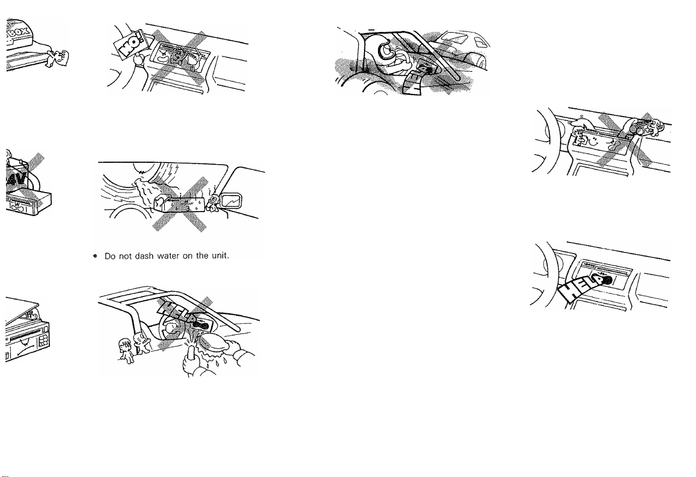
« Do not place the unit, where it will be ex
posed to direct sunlight or dose to heat
ing device.
If an abnormal smell or smoke is detect
ed, immediately turn the power off.
if you have difficulty in installing the set
in your car, please contact your
KENWOOD dealer.
(En)
Page 3

screws (05 X 50)
4
mmn
on and wiring, remove the
3ut and output cords of the system,
ound to the metal chassis of the car.
iwer supply lead iyeilow}.
nd after confirming the installation and wirings are correct, connect the
the battery.
trol
jntro! adjasts the input sensitivity
y to 6.0 V continuously, enabling
5 systems. This unit has been set
nit
.)
Amplifier input
, sensitivity
0.1 V
0.3-0.5 V
terminai of the battery to prevent short-
INPUT
SENSITIVITY
0.3
Air outlet
2, installation location
CAUTION
When making the hole,
do not damage the fuel
tank, brake tube, wiring
harnesses, etc. on the
other side.
CUfCiy lUI Scsiwiy UMVMiy.
•Use screws supplied as
accessories when install
ing the unit,
•Install the unit in a wellventilated place and do
not place the (heavy) ob
ject on it.
• This unit incorporates a
cooler fan, which starts
rotation automatically
when the temperature
rises during use. Take
care not to block the air
inlet and outlet for this
fan.
Input sensitivity
controller for B
Input sensitivity
controller for A
Since the power amplifier has no parts which require operation, it can be installed at a
position away from the driver's seat without any hinderances.
As generally accepted positions for its installation, places such as inside the trunk, etc.
can be considered.
Use the extension cables. CA-5W (0.5 m), CA-15W dm), CA-25W (2 m), CA-45W (4 m),
and CA-65W (6 m) (optional) when the connected models are to be installed away from
the power amplifier.
(En) 5
Page 4

USE OF THE OPERATIOH PANEL ACCORDING TO SYSTEM TYPE
.......................................................
mill
...........
....
..............................................................
Ill
.........
..................
.
HOW TO USE THE SUB WOOFER SYSTEM
SUB WOOFER
FREQUENCY ' ] =P on
OOFF ONO
30
aoo(Hz]
HOW TO USE THE HIGH PASS
FILTER SYSTEM
HFPASS
30 aooiH^i
Turning ON the high pass switch can cut the
low frequency range at the A side output.
The high pass frequency can be adjusted by
the knob.
I
OPF ON
OOFF ONO
The upper mode switch is for A, while the low
er for B.
By setting the switch on the right to ON, you
can set the B output of this unit for sub woof
er output (monaura! output). The contro! on
the left can be used to adjust the sub woofer
cut-off frequency.
HOW TO USE THE MODE
SWITCH I
Set this switch according to the impedance of
the speakers or the output method, as shown
below.
When 4-ohm When 2-ohm
speakers are speakers are
connected connected
Efl e«ooeo
When using
a bridged
output(See
the right
statement.)
(DUD
m SYSTEM EXAMPLES
Setting the mode switch to the bridge output can double the output of this unit (Monaural
output for 4-ohm speakers}. The following systems can be assumed by combining this unit
with the foregoing function or sub woofer system.
Cassette receiver/
Graphic equalizer
etc.
Output
j / A left input
B left iriput
B left input
B right input
B left input
B right input
Left output
left speaker
Right speaker
Left output
Right output
A left input
A right input
qQ Left speaker
Right speaker
Sub-woofer speaker
Left output
Right output
A left input
A right input
Left speaker
< Selecting condition of switch >
Output
Switch
Mode
switch
Sub-woofer
switch
A output B output
Bridged Bridged
OFF
< Selecting condition of switch >
Output
Switch
Mode
switch
Sub-woofer
switch
A output
2Q/4 0
B output
Bridged
-
ON
< Selecting condition of switch >
Output
Switch
Mode
switch
Sub-woofer
switch
A output
2 0/4 0
~
B output
2 0/4 0
ON
6 !En)
Right speaker
Sub-woofer speaker
Sub-woofer speaker
(£n) 7
Page 5

Page 6

TROUBLESHOOTING GUIDE
What often appears to be a malfunction is often due to user error in operation or connection.
When trouble occurs with your unit, please check the following before calling for service.
Symptom Cause
The sound ievel is tow.
(No sound from one
side.)
The sound quality is
bad. (The sound is dis
torted.)
A speaker cord has become uncon
nected.
1. The speakers are connected to
2. A speaker cord is pinched by a
the same wires,
screw in the car body.
Check the speaker cord con
nections.
1. Connect each speaker tennina!
to its respective speaker output,
2, Check the speaker wiring.
Remedy
SPECIFICATIONS
Specifications subject to change without notice.
Audio section
Max Power Output (1 kHz, 4 fl)
2 Channel Mode
3 Channel Mode........................................................................................80 Wx2+160 W
4 Channel Mode....................................................................................80 Wx2 + 80 Wx2
Power Output
2 Channel Mode (1 kHz, 412, 0.5% THD).........................................................80 W + 80 W
3 Channel Mode (20 Hz~-20 kHz, 4 12, less than 0.5% THD}............................40 Wx2
4 Channel Mode (20 Hz^20 kHz, 4 12, less than 0,5% THD}
Frequency Response (~3 dB)..............................................................................2 Hz-100 kHz
Signal to Noise Ratio...:....................................................................................................
Input Sensitivity (rated output} MAX.......................................................................................0.1 V
Input Impedance.........................................................................................................................10 kO
Damping Factor (100 Hz).....................................................................................More than 150
Sub-Woofer Frequency (variable).............................................................................30-200 Hz
High-Pass Filter Frequency (variable)
General
operating Voltage.........................................................................14.4 V (11 - 16 V allowable)
Current Consumption (MAX.)................................................................................................30 A
Dimensions (WxHxD)...................................................................................280x50x200 mm
Weight...................................................................................................................3.1 kg (6.8 lb)
...........................................................................................
or (1 kHz, 2 12, 0.5% THD)
+ n kHz, 4 0, 0.5% THD}
............... ..........................
...................................................................
...........
160 W-t-160 W
.........
40 Wx2
40 Wx2 + 40 Wx2
(1 kHz, 2 12, 0.5% THD)...............................................40 Wx2 + 40 Wx2
105 dB
MIN.......................................................................................5.0 V
......................................................................
30-200 Hz
(11 X1-15/16X7-7/8 in.)
80 W
10 (Efi)
 Loading...