

Page 1

KENWOOD
KAC-8401
4-CHANNEL POWER AMPLIFIER
b
page
2-13
INSTRUCTION MANUAL
AMPLIFICATEUR DE PUISSANCE 4 CANAUX
b
page
14-25
MODE D’EMPLOI
b
pagina
AMPLIFICADOR DE POTENCIA DE 4 CANALES
26-36
MANUAL DE INSTRUCCIONES
KENWOOD
CORPORATION
Take the time to read through this instruction manual.
Familiarity with installation and operation procedures will help
you obtain the best performance from your new power amplifier.
For
your
Record the serial number, found on the back
designated on the warranty card, and in the space provided below.
Refer to the model and serial numbers whenever you call upon your
KENWOOD
Model
0
PRINTED
records
dealer for information or service on the product.
KAC-8401 Serial number
IN
CHINA
B64-2573-00/00
(KV/EV)
of
the unit, in the spaces
Page 2
Safety precautions
I
AWARNING
To
prevent injury or fire, take the following
precautions:
When extending the ignition, battery, or
ground wires, make sure to use automotivegrade wires or other wires with
(AWG
deterioration and damage to the wire coating.
To prevent a short circuit, never put or leave
any metallic objects (such as coins or metal
tools) inside the unit.
If the unit starts to emit smoke or strange
smells, turn off the power immediately and
consult your Kenwood dealer.
Do not touch the unit during use because the
surface of the unit becomes hot and may
cause burns if touched.
1
ACAUTION
To
prevent damage to the machine, take the
following precautions:
Be sure the unit
power supply with
connection.
Do not open the top or bottom covers of the
unit.
Do not install the unit in a spot exposed to
direct sunlight or excessive heat or humidity.
Also avoid places with too much dust or the
possibility of water splashing.
When replacing a fuse, only use a new one
with the prescribed rating. Using
the wrong rating may cause your unit to
malfunction.
To prevent a short circuit when replacing
fuse, first disconnect the wiring harness.
pEEl
If you experience problems during
installation, consult your Kenwood dealer.
If the unit does not seem to be working right,
consult your Kenwood dealer.
FCC
WARNING
This equipment may generate or use radio
frequency energy. Changes or modifications
to this equipment may cause harmful
interference unless the modifications are
expressly approved in the instruction manual.
The user could lose the authority to operate
this equipment if an unauthorized change or
modification is made.
I
10)
or more to prevent wire
1
is
connected to
a
negative ground
a
5
mm2
a
12V
a
fuse with
DC
Cleaning the unit
If the front panel gets dirty, turn off the power
and wipe the panel with
soft cloth.
I
ACAUTION
Do not wipe the panel with a hard cloth or
cloth dampened by volatile solvents such as
paint thinner and alcohol. They can scratch the
surface of the panel and/or cause the indicator
letters to peel off.
To
prevent battery rise
When the unit is used in the ACC
without turning the engine
battery. Use it after starting the engine.
I
a
dry silicon cloth or
ON,
Protection function
There
is a Protection function installed in the
unit to protect the unit and speakers from
various problems. When Protection operates,
the indicator informs you of the condition.
(Refer to page
5)
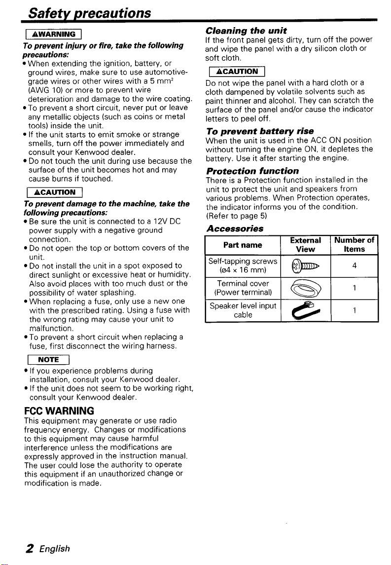
Accessories
External
View
Self-tapping screws
I
a
Part name
(04x
16
mm)
a
ON
position
it depletes the
Number
Items
of
2
English
Page 3
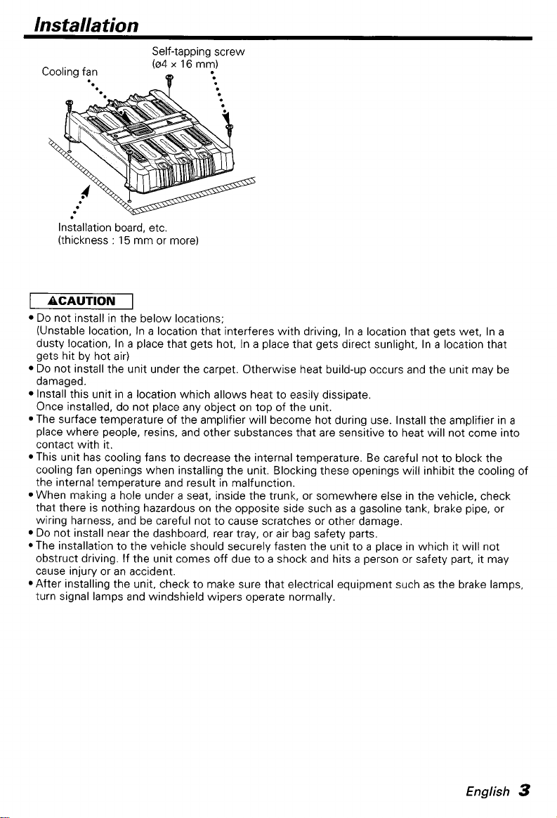
lnstalla tion
Self-tapping screw
(04
x
16
Cooling fan
Installation board, etc.
(thickness
I
ACAUTION
Do
not install in the below locations;
(Unstable location, In
dusty location, In a place that gets hot, In a place that gets direct sunlight, In
gets hit by hot air)
Do
not install the unit under the carpet. Otherwise heat build-up occurs and the unit may be
damaged.
Install this unit in a location which allows heat to easily dissipate.
Once installed, do not place any object on top of the unit.
*The surface temperature of the amplifier will become hot during use. Install the amplifier in
place where people, resins, and other substances that are sensitive to heat will not come into
contact with it.
*This unit has cooling fans to decrease the internal temperature. Be careful not to block the
cooling fan openings when installing the unit. Blocking these openings will inhibit the cooling of
the internal temperature and result in malfunction.
When making a hole under a seat, inside the trunk, or somewhere else in the vehicle, check
that there
wiring harness, and be careful not to cause scratches or other damage.
Do
not install near the dashboard, rear tray, or air bag safety parts.
*The installation to the vehicle should securely fasten the unit to
obstruct driving. If the unit comes off due to a shock and hits
cause injury or an accident.
*After installing the unit, check to make sure that electrical equipment such as the brake lamps,
turn signal lamps and windshield wipers operate normally.
:
15
mm or more)
I
a
is
nothing hazardous on the opposite side such as a gasoline tank, brake pipe, or
my)
location that interferes with driving, In a location that gets wet, In a
a
place in which it will not
a
person or safety part, it may
a
location that
a
English
3
Page 4
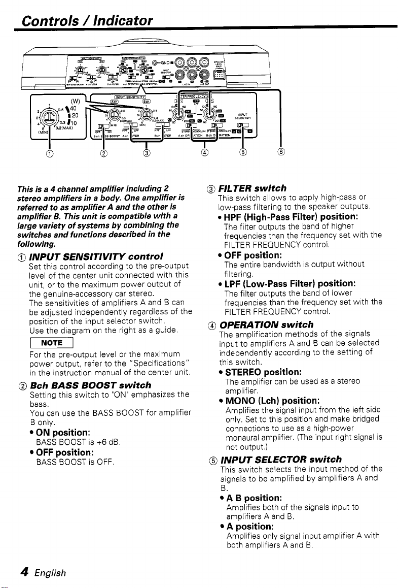
Controls / Indicator
This is a 4 channel amplifier including
stereo amplifiers in a body. One amplifier is
referred to as amplifier
amplifier
large variety of systems by combining the
switches and functions described in the
following.
@
@
B.
This unit is compatible with a
INPUT SENSITIVITY control
Set this control according to the pre-output
level of the center unit connected with this
unit, or to the maximum power output
the genuine-accessory car stereo.
The sensitivities of amplifiers A and B can
be adjusted independently regardless of the
position of the input selector switch.
Use the diagram on the right as a guide.
I
NOTE
For the pre-output level or the maximum
power output, refer to the "Specifications"
in the instruction manual of the center unit.
I
Bch BASS
Setting this switch to "ON" emphasizes the
bass.
You can use the BASS BOOST for amplifier
B only.
ON
position:
BASS BOOST is
OFF
position:
BASS BOOST is OFF.
BOOST
+6
A
and the other
switch
dB.
2
is
of
6
@
@
6
FILTER switch
This switch allows to apply high-pass or
low-pass filtering to the speaker outputs.
0
HPF (High-Pass Filter) position:
The filter outputs the band of higher
frequencies than the frequency set with the
FILTER FREQUENCY control.
OFF
position:
The entire bandwidth is output without
filtering.
0
LPF (Low-Pass Filter) position:
The filter outputs the band
frequencies than the frequency set with the
FILTER FREQUENCY control.
OPERATION switch
The amplification methods of the signals
input to amplifiers A and B can be selected
independently according to the setting of
this switch.
STEREO
The amplifier can be used as a stereo
amplifier.
MONO
Amplifies the signal input from the left side
only. Set to this position and make bridged
connections to use as a high-power
monaural amplifier. (The input right signal is
not output.)
@
INPUT SELECTOR switch
This switch selects the input method
signals to be amplified by amplifiers A and
6.
A
Amplifies both of the signals input to
amplifiers A and 6.
A
Amplifies only signal input amplifier A with
both amplifiers A and 6.
position:
(Lch) position:
B
position:
position:
of
lower
of
the
4
English
Page 5
0
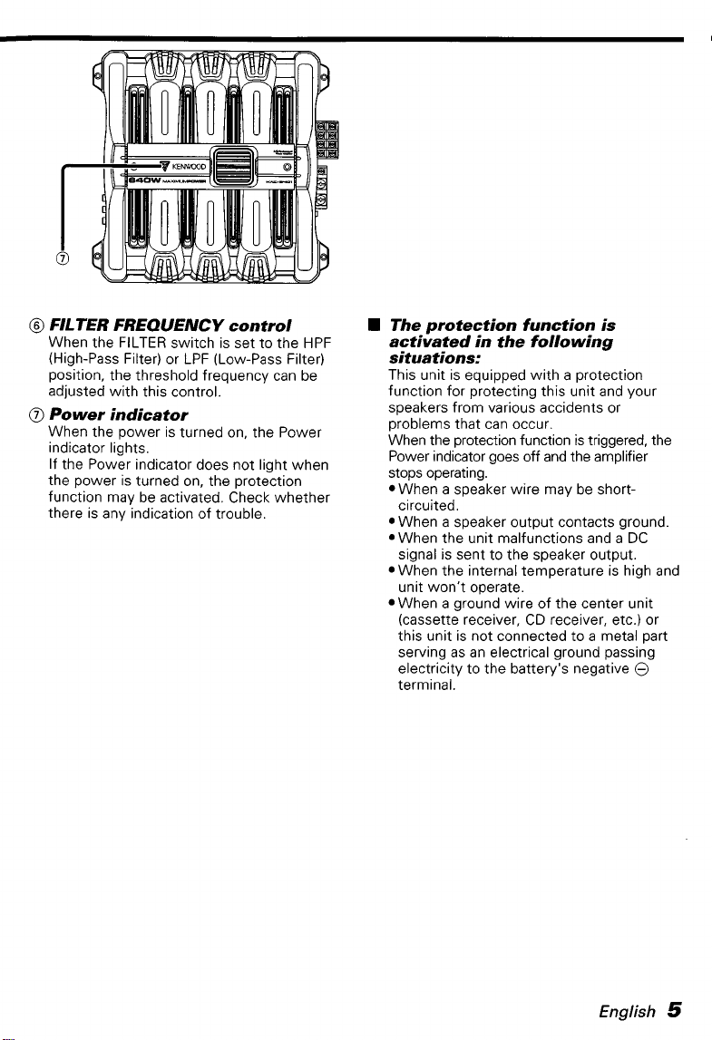
FILTER FREQUENCY control
When the FILTER switch is set to the HPF
(High-Pass Filter) or LPF (Low-Pass Filter)
position, the threshold frequency can be
adjusted with this control.
0
Power indicator
When the power is turned on, the Power
indicator lights.
If the Power indicator does not light when
the power is turned on, the protection
function may be activated. Check whether
there is any indication of trouble.
The protection function is
activated in the following
situations:
This unit is equipped with a protection
function for protecting this unit and your
speakers from various accidents or
problems that can occur.
When the protection function is triggered, the
Power indicator goes
stops operating.
When a speaker wire may be shortcircuited.
When a speaker output contacts ground.
When the unit malfunctions and a DC
signal is sent to the speaker output.
When the internal temperature is high and
unit won't operate.
When a ground wire of the center unit
(cassette receiver, CD receiver, etc.) or
this unit is not connected to
serving as an electrical ground passing
electricity to the battery's negative
terminal.
off
and the amplifier
a
metal part
@
English
5
Page 6

Connection
W
Terminal names
0
Fuse
(40
A)
VJ
If you can't find the specified capacity fuse
your store etc., consult your Kenwood dealer.
@
Battery terminal
@
Ground terminal
0
Power control terminal
Controls the unit ON/OFF.
I
NOTE
Controls the unit power. Be sure to connect
it
with all the systems.
0
Speaker output terminals
Stereo Connections:
When you wish to use the unit as a stereo
amplifier, stereo connections are used.
The speakers to be connected should
have an impedance of
When multiple speakers are to be
connected, ensure that the combined
impedance is
channel.
Bridged Connections:
When you wish to use the unit as
output monaural amplifier, bridged
connections are used. (Make connections
to the LEFT channel
.
channel
The speakers to be connected should
have an impedance of
When multiple speakers are to be
connected, ensure that the combined
impedance is
1
ACAUTION
The rated input of the speakers should be
no less than the maximum output of the
6
English
I
2sL
or greater.
252
or greater for each
0
0
SPEAKER OUTPUT terminals.)
4Q
and the RIGHT
452
or greater.
or greater.
I
a
at
high-
amplifier. Otherwise malfunction may
result.
@
RCA
cable ground lead terminal
When using an RCA cable with a ground
lead attached, connect the ground lead to
this terminal.
@
LINE IN terminal
@
LINE OUT terminal
These jacks output respectively the signals
input to amplifiers A and B. They always
output the stereo signals regardless of the
position of the OPERATION switch.
@
Speaker level input terminals
-1
The genuine-accessory car stereo shall
have a maximum power output of no
more than
Do
from a power amplifier (Optional) to the
speaker level input terminals of this unit,
for this may cause malfunction or
damage.
Do
RCA cable input jacks and the speaker
level input terminals simultaneously, for
this may cause malfunction or damage.
Connect the power control lead to a
power supply which can be turned
ON/OFF by the ignition key switch (ACC
line). With this connection, shock noise
may be generated when the power of the
genuine-accessory car stereo is switched
0
NIO
40
not connect the speaker output leads
not connect cables and leads to both
W.
F F.
Page 7

H
Installation procedure
Since there are large variety of settings and
connections possible according to applications,
read the instruction manual well to select the
proper setting and connection.
1,
Remove the ignition key and disconnect the
negative
prevent short circuits.
2.
Set the unit according to the intended usage.
3.
Connect the input and output wires of the
units.
4.
Connect the speaker wires.
5.
Connect the power wire, power control wire
and grounding wire following this order.
6.
Install the unit in the car.
7.
Connect the negative @ terminal of the
battery.
I
AWARNING
To prevent fire caused by a short in the wiring,
connect
battery's positive terminal.
1
If sound is not output normally, immediately
turn power off and check connections.
Be sure to turn the power off before
changing the setting of any switch.
If
then replace the fuse with one of the same
rating.
Check that no unconnected wires or
connectors are touching the car body.
not remove caps from unconnected wires or
connectors to prevent short circuits.
Connect the speaker wires to appropriate
speaker connectors separately. Sharing the
negative wire of the speaker or grounding
speaker wires to the metal body of the car
can cause this unit to fail.
*After installation, check that the brake
lamps, winkers, and wipers work properly.
@
terminal of the battery to
I
a
fusible link or breaker nearby the
ACAUTION
the fuse blows, check wires for shorts,
1
Do
H
Wiring
Take the battery wire for this unit directly
from the battery. If it's connected to the
vehicle's wiring harness, it can cause blown
fuses etc.
If a buzzing noise is heard from the speakers
when the engine is running, connect
noise filter (optional) to each of the battery
wire.
Do
not allow the wire to directly contact the
edge of the iron plate by using Grommets.
Connect the ground wire to a metal part of
the car chassis that acts as an electrical
ground passing electricity to the battery's
negative
on if the ground wire is not connected.
Be sure to install a protective fuse in the
power cord near the battery. The protective
fuse should be the same capacity as the
unit's fuse capacity or somewhat larger.
For the power cord and ground, use a vehicle
type (fireproof) power wring cord with
current capacity greater than the unit's fuse
capacity. (Use
diameter
When more than one power amplifier are
going to be used, use
wire and protective fuse of greater current-
handling capacity than the total maximum
current drawn by each amplifier.
W
*The rated input power of the speakers that
are going to be connected should be greater
than the maximum output power (in Watts) of
the amplifier. Use
power ratings that are less than the output
power of the amplifier will cause smoke to be
emitted
*The impedance
going to be connected should be
greater (for stereo connections), or
greater (for bridged connections). When more
than one set of speakers are going to be
used, calculate the combined impedance of
the speakers and then connect suitable
speakers to the amplifier.
@
terminal.
of
5
Do
a
power wiring cord with
mm2 (AWG
a
Speaker Selection
of
speakers having input
as
well as damage.
of
the speakers that are
not turn the power
10)
power supply wiring
a
line
a
or greater.)
2Q
or
4Q
or
a
4
Q
1..
. . .
Combined impedance
0..
4Q
English
7
Page 8

Connection
RCA cable ground terminal
A channel
Left input
A channel B channel
Right input Right input
1.1.-.-.-.-.-.-.1.-._._._.1.1._._._.1.1.~.-.-.-.-.-.-.
(Speaker level input Connections)
Cable Color
m
0
0
1
of
Achannel
Left
Left
B channel
Right
the
connector
j0
0
White
0
White/Black
@
Green/Black
Purple Car fuse box
0
Purole/Black
:
RCA cable"
*
B channel
:
Left input Power control wire
c+..
(Blue/ White)
...........
8
English
Battery
ACC
............
Page 9

Speaker wire connection
I"
Commercially available parts
I
.
. .
(Stereo Connections)
Lead terminal*
17
W
Power wire connection
-.-
-1
----I
A channel
Left speaker
11
B channel
Right speaker
B channel
Left speaker
A channel
Speaker (Bridged)
B channel
Speaker (Bridged)
:......+
Protective Fuse"
II
Ground wire*
Battery
\
English
9
Page 10

System examples
rn
4-channel system
")
rn
I
CENTERUNIT
3-channel system
r
#
0
mm
........
Front Left speaker
Front Right speaker
Rear Left speaker
Rear Right speaker
Left speaker (High pass)
Right speaker (High pass)
Subwoofer
(Bridged)
(L + R)
131
ILf
I
I
CENTERUNIT
L
h7
Page 11

Tri-mode
CENTER
.Principle
Method of frequency band division using a coil and capacitor.. . in case of GdB/oct. slope
0
dB
-3
dB
UNIT
I
of
Tri-mode
Crossover Frequency
/
\;/
Frequency
...........
I
Coil
CaDacitor
L=
(High pass)
L,
r.
(L):
Passes low frequencies and blocks high
frequencies. (Low pass)
(CI:
Passes hiah freauencies and blocks low
..
frequenci&. (High pass)
~
15'
fc
(mH)
Subwoofer
(L + R)
(Bridged)
fc=Cut of Freauencv (Hz)
R=Speaker Impedance
..
(Q)
.Example:
When it
impedance of 4 ohms.
Prepare commercially-available coil and capacitor with the closest ratings to the results
calculated from the formula above. The capacitor rating should be as close as possible to
(pF)
I
ACAUTION
*If you wish to bridge-connect a speaker, the speaker impedance must be no less than 4 ohms.
Connecting a speaker with an impedance lower than
Be sure to connect capacitors to speakers to which high frequencies will be passed. Failure to
do
Ensure that the withstand voltage and current ratings of the capacitors (C) and coils (L) are
sufficient.
is
required to set a crossover frequency of
and the coil rating should be as close
as
possible to
120
5.3
I
4
ohms may damage the unit.
so
will
result in a drop of the combined impedance with the subwoofer.
Hz
using speakers with an
(mH).
331.25
Page 12

Troubleshooting Guide
What might appear to be a malfunction in your unit may just be the result of slight
misoperation or miswiring. Before calling service, first check the following table for possible
problems.
PROBLEM POSSIBLE CAUSE SOLUTION
No
sound.
(No sound from one side.)
(Blown fuse.)
Input (or output) cables are
disconnected. cables.
Protection circuit may be
activated. to "Indicator".
Volume is too high.
The speaker cord is shorted.
Connect the input (or output)
Check connections by referring
Replace the fuse and use lower
volume.
After check the speaker cord and
fixing the cause of the short,
replace the fuse.
The output level is too
small (or too large).
The sound quality is bad.
(The sound is distorted.)
The input sensitivity adjusting
control is not set to the correct
position.
The speakers wire are
connected with wrong
polarity. wires well.
A
speaker wire is pinched by a
screw in the car body.
The switches may be set
improperly. referring to "System examples".
@
/
Adjust the control correctly
referring to "Controls".
Connect them properly checking
@ / @
the
@
Connect the speaker wire again
so
anything.
Set switches properly by
of the terminals and
that
it
is not pinched by
72
English
Page 13

Specifications
Specifications subject to change without notice.
Audio
Section
Max Power Output
Rated Power Outpu
Normal (4
Q)
(20
(4
Q)
(DIN : 45324,
(2
Q)
(1 kHz,
Hz
General
Operating Voltage
Current Consumption (4
Dimensions (W
Weight
x H x
.....................................................................................
.................................................................................................
-
20 kHz, 0.08
0.8
%
Yo
+B
THD)
THD)
=
14.4V)
......................................
.......................................
...............................................................
.............................................................
.................
Q,
1
D)
......................................................................................
.............................................
....................................................
320 W x 2
.................................
14.4V(11 - 16Vallowable)
11-1/4~2-1/4~ 10-9/16inch
285 x 57 x 268 mm
................
2.96 kg (6.5 Ibs)
39 A
English
13
Page 14

This warranty will be honored only in the U.S.A.
KENWOOD LIMITED WARRANTY FOR CAR STEREO COMPONENTS
IS
HOW LONG
Kenwood U.S.A. Corporation ("Kenwood") warrants this product for a period of one
purchase.
WHAT
Except as specified below, this warranty covers ail defects in material and workmanship in Kenwood car stereo
components. The following are not covered by the warranty:
1.
Any product which is not distributed in the U.S.A. by Kenwood or which is not purchased in the U.S.A. from an
authorized Kenwood car stereo dealer or an automobile dealer, unless the product is purchased through the USA
Military Exchange Service.
2.
Any product on which the serial number has been defaced, modified or removed.
3.
Damage, deterioration or malfunction resulting from:
Any shipment of the product (claims must be presented to the carrier).
a.
Installation or removal of the product.
b.
Accident, acts of nature, misuse, abuse, neglect, unauthorized product modification or failure to follow
c.
instructions supplied with the product.
Repair or attempted repair by anyone not authorized by Kenwood.
d.
Any other cause which does not relate to a product defect.
e.
WHO
IS
This warranty is enforceable only by the original purchaser.
WHAT WE WILL PAY
We will pay for all labor and material expenses for covered items, Payment of shipping charges is discussed in the next
section of this warranty.
HOW TO OBTAIN WARRANTY SERVICE
If your KENWOOD product ever needs service:
1.
Take or ship it to any KENWOOD Authorized Service Center in the U.S.A. along with &complete description of the
problem. (if you are uncertain as to whether a Service Center is authorized, please call
Service Center.
Although you must pay any shipping charges if
2.
the return shipping charges if the repairs are covered by the warranty within the United States.
Whenever your units are taken or sent for warranty service, you must include a copy of the original dated sales receipt
3.
as proof of warranty coverage.
LIMITATION
ALL IMPLIED WARRANTIES, INCLUDING WARRANTIES
PURPOSE, ARE LIMITED IN DURATION TO THE LENGTH OF THIS WARRANTY.
EXCLUSION
KENWOODS LIABILITY FOR ANY DEFECTIVE PRODUCT
AT OUR OPTION. KENWOOD SHALL NOT BE LIABLE FOR:
1.
INSTALLATION
CAR STEREO COMPONENTS, DAMAGES BASED UPON INCONVENIENCE, LOSS
2.
ANY OTHER DAMAGES, WHETHER INCIDENTAL, CONSEQUENTIAL
SOME STATES DO NOT ALLOW LIMITATIONS ON HOW LONG AN IMPLIED WARRANTY LASTS AND/OR DO NOT ALLOW
THE EXCLUSION
EXCLUSIONS MAY NOT APPLY TO YOU.
This warranty gives you specific legal rights, and you may also have other rights which vary from state to state.
If a problem develops during or after the Limited Warranty Period, or if you have any questions regarding the Operation
of the product, you should contact your KENWOOD Authorized Dealer or Authorized Service Center. If the problem or your
question is not handled to your satisfaction, please contact our Customer Relations Department at the address listed
below:
THE WARRANTY
IS
COVERED AND WHAT
PROTECTED
FOR
1-800-536-9663).
OF
IMPLIED WARRANTIES
OF
DAMAGES
OR
REMOVAL CHARGES, DAMAGE TO OTHER PROPERTY CAUSED
OR
LIMITATION OF INCIDENTAL
Box
P.0
IS
NOT COVERED
it
OR
CONSEQUENTIAL DAMAGES,
KENWOOD U.S.A. CORPORATION
2274%
2201 East
Dominguer
Tel: 1310)
(1)
year from the date of original
1-800-KENWOOD
is necessary to ship the product for warranty service, we will pay
OF
MERCHANTABILITY AND FITNESS FOR A PARTICULAR
IS
LIMITED
TO
Street,
639-5300
THE REPAIR
Long
OR
OTHERWISE.
Beach CA
OR
REPLACEMENTOF THE PRODUCT
BY
ANY DEFECTS IN KENWOOD
OF
USE
SO
THE ABOVE LIMITATIONS AND
908016745
OF
THE PRODUCT;
for the nearest
OR
 Loading...