

Page 1

STEREO POWER AMPLiFlER
KAC-1021
INSTRUCTION MANUAL
KENWOOD CORPORATION
Take the time to read through this instruction manual.
Familiarity with installation and operation procedures will
help you obtain the best performance from your new pow
er amplifier.
For your records
Record the serial number found on the bottom of the unit in
the spaces designated on the warranty card and in the space
provided below. Refer to the model and serial numbers
whenever you call upon your KENWOOD dealer for informa
tion or service on this product.
Model KAC-1021 Serial number------------------------------------------
©PRINTED IN JAPAN 850-7924-00(K)ft)
SO/12 1110 987654321 89/12 1110
Page 2
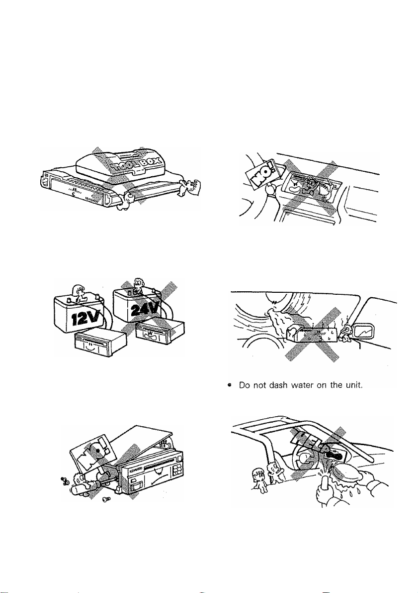
AWARNING
TO PREVENT ELECTRIC SHOCK, FIRE AND OTHER INJURY. PLEASE NOTE THE FOLLOWINGS;
To keep good ventiiation, do not anything
on top of the unit.
The unit is designed to be connected
12 V DC and negative grounding.
Do not open enclosure, such as front
panel, top or bottom cover.
® Do not drop pieces of meta!, needles,
coins and other electrically conductive
materials into the unit.
Do not place the unit, where it will be ex
posed to direct sunlight or close to heat
ing device.
2 (EnJ
Page 3
Do not place the unit in areas of exces
sive dust, high humidity or on unstable
surfaces.
KAC-1021 is designed to be profession
ally installed. The length and nature of
your warranty are dramatically affected
if you attempt to install it yourself. Skill
and experience are required to achieve
high-end sound, reliability, and appear
ance in a high-powered autosound sys
tem. If you want to install your own unit,
read this booklet completely, research
speaker systems and source units exten
sively.
Under normal operation, the amplifier
may become too hot to touch. Please use
caution.
When removing the amplifier, dis
connect the fusible link at the battery pri
or to disconnecting the amplifier.
CLEANING
1. Turn the po\A/er off, before cleaning the
unit.
2. Do not use any type of abrasive pad, thin
ner, benzine and any such kind of
objects.
3. Wipe the front panel and other exterior
surfaces of the unit with a soft dry cloth
or a soft cloth lightly moistened with a
neutral detergent.
If an abnormal smell or smoke is detect
ed, immediately turn the power off.
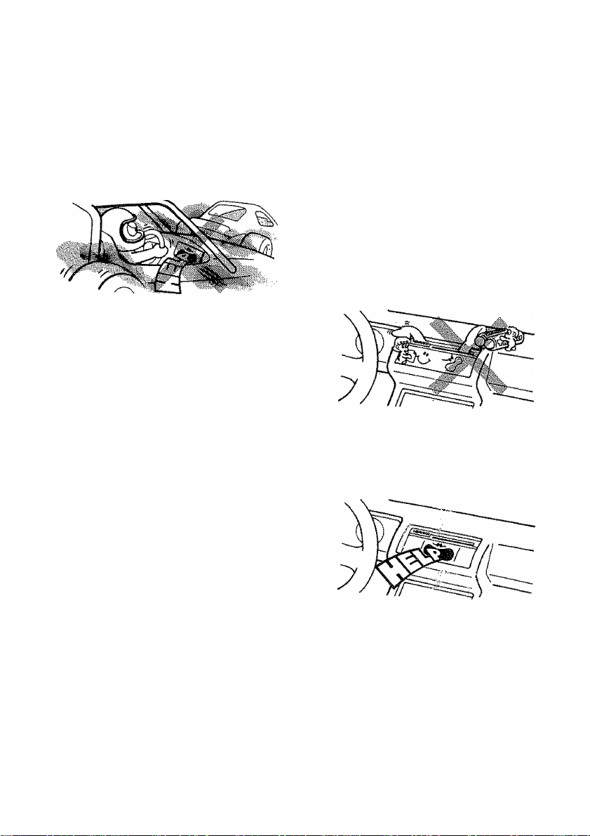
If you have difficulty in installing the set
in your car, please contact your
KENWOOD dealer.
(En)
Page 4

Battery and charging system
KAC-1021 amplifier draws enough current to put a substantial additional demand on automotive
eiectricai systems. When piayed very loudly, the KAC-1021 may draw 20 to 40 Amperes
on the average, with peak demands up to 120 Amperes!
A typical stock battery and alternator in good condition will handle moderate to low average
levels, with occasional brief episodes of hard use. However, alternator and battery life will
be shortened. We strongly recommend that a premium deep-cyde battery and heavy-duty
alternator be used with KAC-1021 systems.
If the sound system will be used when the car is not running, the battery will obviously be
discharged ~ perhaps enough to prevent restarting. The discharge/recharge cycle will reduce
battery life, and alternator life will be shorter because of the high-current recharge requirements.
If problems arise:
a} Use a premium battery or deep-discharge marine battery.
b) Use a heavy duty alternator.
c) Use a trickle-charger or battery charger.
d) Install a second battery for the amp, with a switching system for recharge.
4 (En)
Page 5

Mo.
0
Part name External View
Power supply cord (Yellow) 1
Number of
units
Fusible link
@
Tapping screws (^5x50)
®
g trr)Tm>
1
4
(En) 5
Page 6

CONNECTIONS
K Before making connections
» Before installing the amplifier, be sure to disconnect the wire from the battery's negative
(-) terminal to prevent hazards caused by short-circuiting,
« When the amplifier installation and wiring have been completed, first check that they are
correct, then set the volume control to the minimum position to prevent speaker damage
due to high volume when power is supplied. After this, re-connect the battery's negative
[-) terminal which was disconnected previously,
M
Caution on fuse
When the fuse is blown, first check that the cables are not short-circuited, then replace it
with a 15 Ax4 (60 A) fuse. (Use a 30 Ax4 fuse when measuring the maximum power
output.)
M
Caution on speakers
This unit is an amplifier featuring a large power output of 420 W -t- 420 W (840 W in the
case of a bridged output) (when speakers with an impedance of 4 ohms are used).
Therefore, the speakers to be used should have a high maximum input capacity. If you have
to use speakers with a small maximum input rating, regulate the volume with careful con
sideration to prevent speaker damage. The speakers must have an impedance of more than
4 ohms.
Ü Caution on RCA pin-plug cords
• When an audio system from manufacturers other than KENWOOD is connected to the
RCA pin jacks of this unit, adjust the input sensitivity adjustment potentiometer of this unit
according to the output level of the system.
• Because the RCA pin-plug cord is more sensitive to external noise than the DIN cable,
use consideration when placing the cord.
(En)
Page 7

Thîs unît is provided with a bridged output function which enables you
to double the unit's power output. Since the output becomes monaural
when the bridged output function Is used, systems can be configured
such as those shown below, (for 4 0 speakers)
» When using a KENWOOD DIN output system:
KAC-1021
« When using an RCA pin-piug cord output system:
Power control power supply
(En) 7
Page 8

To exhibit the fuif perfor
mance of this unit, use
speaker cords containing
wires of AWG16 or more.
c(
round lead
Power supply cord
Left speaker
To ground the unit, remove the
coating on the metailic part of the
chassis to which the battery's
negative terminal is con
nected, and attach the grounding
cable securely using a bolt.
c:>
• if you hear noise when starting the en
gine, connect two line noise filters (op
tional) to the power supply cords of
this unit as shown below.
Power supply cord
[j-j {yeîîow}
V
Interior Engine
© Power supply
cord
(Yellow) @
jjiJ (option)
8e sure to use a fusibie link, and
connect it directly to the battery's
positive ® terminal.
The wiring length should be as
short as possible. When an exten
sion is required, use cables with
wires of AWG8 or more.
Soideriess
terminal
When connecting the cord, be sure
to use soideriess terminals and cap
them with shrink tubings.
cjra
Shrink
tubing
Do not allow the cord to direct
ly contact the edge of the iron
plate by using grommets (sup
plied).
©
Battery TÏÏÏÏT
©
(En) S
Page 9

INSTALLATION
1. installation
» When instaliing to the car, install the unit securely for safety driving.
» Use screws supplied as accessories when instaliing the unit.
* Instai! the unit in a well-ventilated piace and do not place the (heavy) object on it.
10 {En}
Page 10

2. Instailation location
Since the power amplifier has no parts which require operation, it can be installed at a
position away from the driver's seat without any hinderances.
As generally accepted positions for its installation, places such as inside the trunk, etc.
can be considered.
Use the extension cables. CA-8L (0.5 m), CA-18L (1 m), CA-28L (2 m), CA-48L (4 m),
and CA-68L (6 m) (optional) when the connected models are to be installed away from
the power amplifier.
This unit incorporates a cooler fan, which starts rotation automatically when the tempera
ture rises during use. Take care not to block the air inlet and outlet for this fan.
(Eni 11
Page 11

TROUBLESHOOTING GUIDE
What often appears to be a malfunction is often due to user error in operation or connection.
When trouble occurs with your unit, please check the following before calling for service.
Symptom Cause Remedy
The sound level is low.
(No sound from one
side.)
The sound quality is
bad. (The sound is dis
torted.)
A speaker cord has become uncon
nected.
1. The speakers are connected to
the same wires.
2. A speaker cord is pinched by a
screw in the car body.
Check the speaker cord con
nections.
1. Connect each speaker terminal
to its respective speaker output.
2. Check the speaker wiring.
SPECIFICATIONS
Specifications subject to change without notice.
Audio section
Max Power Output (1 kHz, 4 i2)
Normal...........................................................................................................420 W4-420 W
Bridged............................................................................................................................840 W
Power Output
Normal {20 Hz~20 kHz, 4 fi, less than 0,08% THD) .....................................220 W-h220 W
Bridged (1 kHz, 4 0, 0.08% THD)
Output Power
Normal (1 kHz, 2 0, 0.08% THD)...................................................................370 W-f-370 W
Frequency Response (-3 dB)...............................................................................2 Hz-'lOO kHz
Sensitivity {rated output) MAX...................................................................................................0.1 V
MIN.................................................................................................5.0 V
Signal to Noise Ratio...........................................................................................................105 dB
Input Impedance....................................................................................................................10 ki2
Damping Factor (100 Hz)...............................................................................More than 5000
Sub Woofer Frequency..............................................................
...................................................................................
..............
30-150 Hz (variable)
440 W
General
Operating Voltage
Current Consumption (MAX.).....................................................................................................60 A
Dimensions (WxHxD)...............................................................;
Weight................................................................................................................6.9 kg (15.2 lb)
12 (En)
........................................................................
(15-3/4x2-3/16x11-13/16 in.)
14.4 V (11-16 V allowable)
...................
400x55x300 mm
 Loading...