

Page 1

COMPACT HI-FI COMPONENT SYSTEM
K-501USB
Read Before Use
Read the opposite side for
the "Operating Procedures".
B60-5655-00 00 MA (E,X) BT 0607
Page 2
Before applying power
Caution : Read this page carefully to
ensure safe operation.
Units are designed for operation as follows.
Australia ........................................................... AC 240 V only
Europe .............................................................. AC 230 V only
Safety precautions
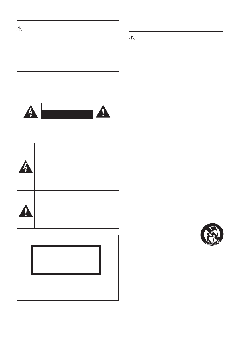
WARNING : TO PREVENT FIRE
OR ELECTRIC SHOCK, DO NOT
EXPOSE THIS APPLIANCE TO
RAIN OR MOISTURE.
CAUTION
RISK OF ELECTRIC SHOCK
DO NOT OPEN
CAUTION: TO REDUCE THE RISK OF ELECTRIC SHOCK,
DO NOT REMOVE COVER (OR BACK). NO USERSERVICEABLE PARTS INSIDE. REFER SERVICING TO
QUALIFIED SERVICE PERSONNEL.
THE LIGHTNING FLASH WITH ARROWHEAD
SYMB OL , WITH IN AN EQUILATERAL T RI
ANGLE, IS INTENDED TO ALERT THE USER
TO THE PRESENCE OF UNINSULATED “DANGEROUS VOLTAGE” WITHIN THE PRODUC T’
S ENCLOSURE THAT MAY BE OF SUFFICIENT
MAGNITUDE TO CONST IT UT E A RI SK OF
ELECTRIC SHOCK TO PERSONS.
THE EXCLAMATION POINT WITHIN AN EQUILATERAL TRIANGLE IS INTENDED TO ALERT
THE USER TO THE PRESENCE OF IMPORTANT
OPERATING AND MAINTENANCE (SERVICING) INSTRUCTIONS IN THE LITERATURE ACCOMPANYING THE APPLIANCE.
The marking of products using lasers
CLASS 1
LASER PRODUCT
The marking this product has been classified as
Class 1. It means that there is no danger of hazardous radiation outside the product.
Location: Back panel
IMPORTANT SAFETY
INSTRUCTIONS
Caution : Read this page carefully to
ensure safe operation.
Read Instructions – All the safety and operating
instructions should be read before the product is
operated.
Retain Instructions – The safety and operating
instructions should be retained for future reference.
Heed Warnings – All warnings on the product and
in the operating instructions should be adhered to.
Fol low Instructions – All operating and use
instructions should be followed.
1. Cleaning – Unplug this product from the wall
outlet before cleaning. Do not use liquid cleaners or
aerosol cleaners. Use a damp cloth for cleaning.
2. Attachments – Do not use attachments not
recommended by the product manufacturer as they
may cause hazards.
3. Water and Moisture – This product shall not be
exposed to dripping and splashing – for example,
near a bath tub, wash bowl, kitchen sink, or laundry
tub; in a wet basement; or near a swimming pool;
and the like. Do not place an object containing
liquid, such as a flower vase, on the appliance.
4. Accessories – Do not place this prod uct on
an unstable cart, stand, tripod, bracket, or table.
The product may fall, causing serious injur y to a
child or adult, and serious damage to the product.
Use only with a cart, stand, tripod, bracket, or table
recommended by the manufacturer. Any mounting
of the product should follow the manufacturer’s
instructions, and should use a mounting accessory
recommended by the manufacturer.
A produ ct an d car t comb inati on
shou ld be moved with ca re. Qu ick
stops, exce ss ive force, an d unev en
surfaces may cause the product and
cart combination to overturn.
5. Ventilation – Slots and openings in the cabinet
are provided for ventilation and to ensure reliable
ope ration of the product and to protect it fro m
over heating, and the se openin gs must not be
blocked or covered. The openings should never be
blocked by placing the product on a bed, sofa, rug,
or other similar surface. This product should not be
placed in a built-in installation such as a bookcase
or rack unless proper ventilation is provided or the
manufacturer’s instructions have been adhered to.
Page 3
I
6. Power Sources –
only from the type of power sou rc e in di ca ted on the
product. If you are not sure of the type of power supply
to your home, consult your product dealer or local power
company.
7.
CAUTION
be equipped with a polarized alternating-current line
plug (a plug having one blade wider than the other).
This plug will fit into the power outlet only one way. This
is a safety feature. If you are unable to insert the plug
fully into the outlet, try reversing the plug. If the plug
should still fail to fit, contact your electrician to replace
your obsolete outlet. Do not defeat the safety purpose
of the polarized plug.
8. Power Cord Protection – Pow er -s up pl y co rd s
sh ou ld be rou te d so th at they are not likel y to be
walked on or pinched by items placed upon or against
them, paying particular attention to cords at plugs,
convenience receptacles, and the point where they exit
from the product.
9. Lightning – For added protection for this product
during a lightning storm, or when it is left unattended
and unused for long periods of time, unplug it from
the wall outlet and disconnect the antenna or cable
system. This will prevent damage to the product due to
lightning and power-line surges.
10. Ove rlo adi ng – Do not ove rlo ad wal l o utl ets ,
extension cords, or integral convenience receptacles as
this can result in a risk of fire or electric shock.
11. Object and Liquid Entry – Never push objects of
any kind into this product through openings as they
may touch dangerous voltage points or short-out parts
that could result in a fire or electric shock. Never spill
liquid of any kind on the product.
12. Servicing – Do not attempt to service this product
yourself as opening or removing covers may expose
you to dangerous voltage or other hazards. Refer all
servicing to qualified service personnel.
13. Damage Requiring Service – Unplug this product
from the wall outlet and refer servi cing to qualified
service personnel under the following conditions:
a) When the power-supply cord or plug is damaged,
b) If liquid has been spilled, or objects have fallen
into the product,
c) If the product has been exposed to rain or water,
d) If th e pr od uct does no t operate norma ll y by
following the operating instructions.
e) If the product has been dropped or damaged in
any way, and
f) When the product exhibits a distinct change in
performance – this indicates a need for service.
g) If an abnormal smell or smoke is detected.
This product should be operated
– Polarization – This product may
14.
Replacement Parts – When replacement parts
are required, be sure the service technician has used
replacement part s specified by the manufacturer
or have the same characteristics as the original part.
Unauthorized substitutions may result in fire, electric
shock, or other hazards.
15. Safety Check – Upon completion of any service
or repairs to this product, ask the service technician
to perform safe ty che cks to determine that the
product is in proper operating condition.
16. Wa ll or Ceili ng Mou nti ng – Thi s pro duc t
shou ld be mo unte d to a wall or ceil in g on ly as
recommended by the manufacturer.
17. Heat – This product should be situated away
from heat sources such as radiators, heat registers,
stoves, or other products that produce heat. Do not
place a flaming object, such as a candle or lantern,
or near the product.
18. Po wer Lin es – An ou tside ante nna sys tem
should not be located in the vicinity of overhead
power lines or other electric light or power circuits,
or where it can fall into such power lines or circuits.
When installing an outside antenna system, extreme
care should be taken to keep from touching such
power lines or circuits as contact with them might
be fatal.
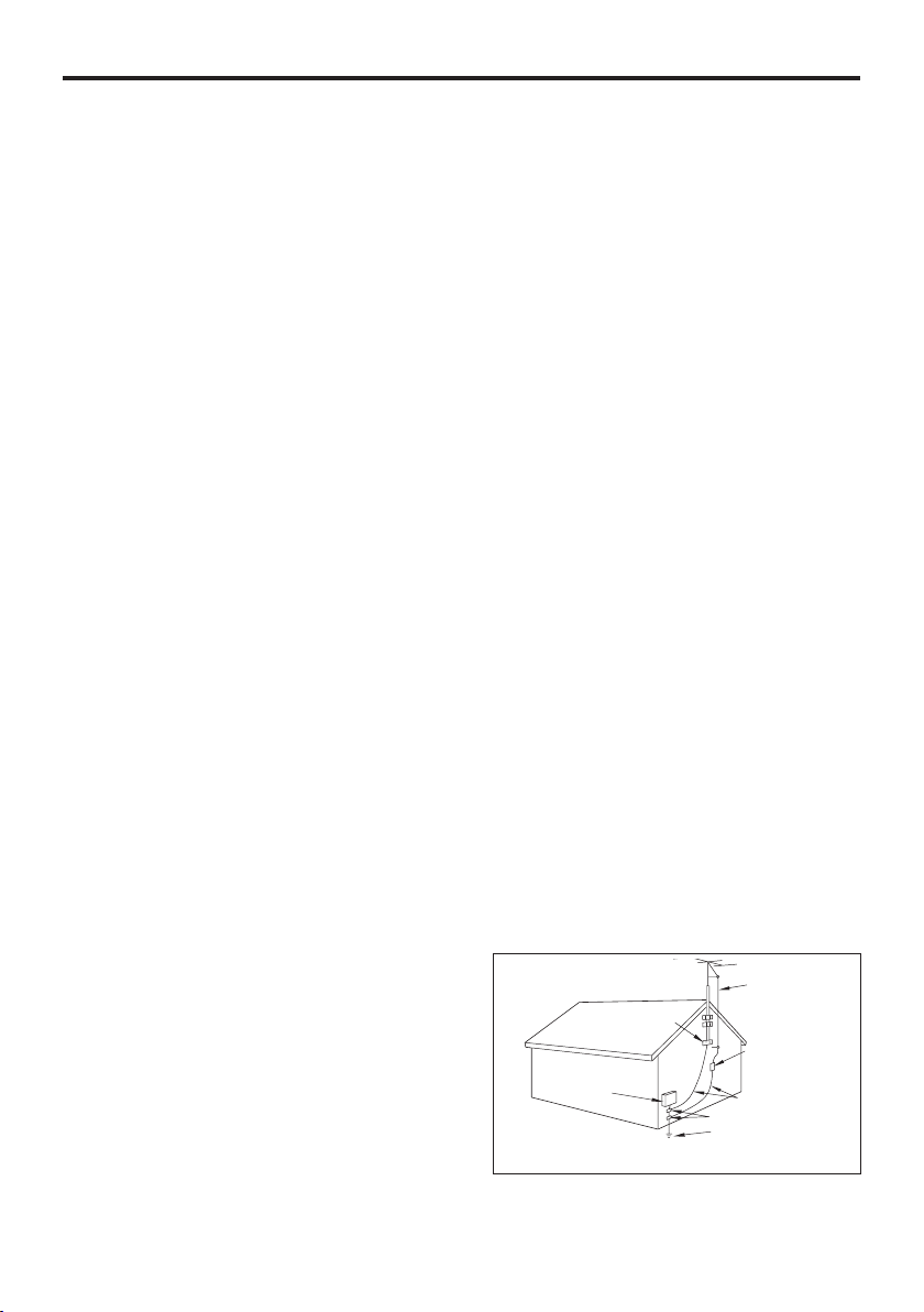
19. Outdoor Antenna Grounding – If an outside
an ten na or ca ble sys tem is con nect ed to the
product, be sure the antenn a or cable system is
grounded so as to provide some protection against
voltage surges and built-up static charges. Article
810 of the Nat io na l Elec trical Code, ANSI /N FPA
70, provides information with regard to p rope r
grounding of the mast and supporting structure,
gr ound ing of th e le ad- in wi re to an an tenn a
di sch arge uni t, si ze of grou ndi ng co ndu cto rs,
location of antenna-discharge unit, connection to
grounding electrodes, and requirements for the
grounding electrode.
EXAMPLE OF ANTENNA
GROUNDING AS PER NATIONAL
ELECTRICAL CODE
GROUND CLAMPS
ELECTRIC
SERVICE
EQUIPMENT
NEC – NATIONAL ELECTRICAL CODE
ANTENNA
LEAD IN WIRE
ANTENNA
DISCHARGE UNIT
(NEC SECTION 810-20)
GROUNDING CONDUCTORS
(NEC SECTION 810-21)
GROUND CLAMP
POWER SERVICE GROUNDING
ELECTRODE SYSTEM
(NEC ART 250, PART H)
Notes:
1. Item 7 is not required except for grounded or
polarized equipment.
2. Item 19 complies with UL in the U.S.A.
Page 4
Information on Disposal of Old Electrical
and Electronic Equipment (applicable for
EU countries that have adopted separate
waste collection systems)
Products with the symbol (crossed-out wheeled bin)
cannot be disposed as household waste.
Old electrical and electronic equipment should be
detrimental effects on our health and the environment.
recycled at a facility capable of handling
these items and their waste byproducts.
Contact your local authority for details in
locating a recycle facility nearest to you.
Proper recycling and waste disposal will
help conserve resources whilst preventing
Page 5
Contents (For "Read Before Use")
To ensure safety, read the items carrying
this marking carefully.
Before applying power ...............................................................................
IMPORTANT SAFETY INSTRUCTIONS ...................2
Accessories/Associated Products .................................................................
Installation ............................................................................................................
Connections .........................................................................................................
Controls, Connectors and Indicators ........................................................
Additional Information ..................................................................................
Before Recording .............................................................................................
Folders and Music Files .................................................................................
How to Use This Volume "Operating Procedures" ...............................
Basic Operation ................................................................................................
Care and Storage .............................................................................................
Specifications ....................................................................................................
2
6
7
8
12
16
19
20
22
24
26
27
Page 6
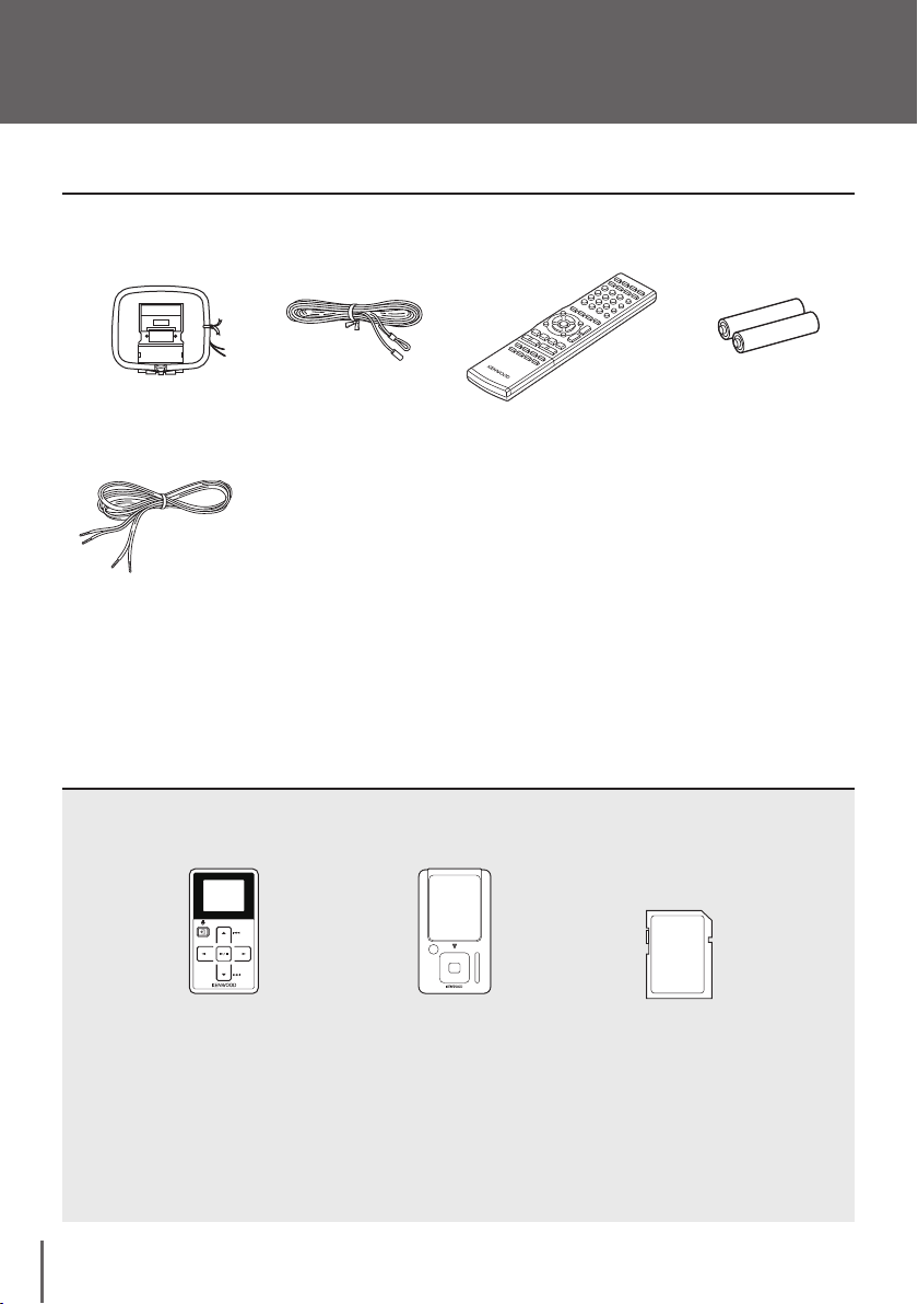
Accessories/Associated Products
Check that all accessories are present in the package.
AM loop antenna
(x 1)
Speaker cords
(2 m x 2)
Packaged together with speakers
If any accessories are missing, or if the unit is damaged or fails to operate, notify your dealer immediately. If
the unit was shipped to you directly, notify your shipper immediately. Kenwood recommends that you retain
the original carton and packing materials in case you need to move or ship the unit in the future.
Keep this manual handy for future reference.
Associated Products
Connect to USB connector
for recording and playback
FM indoor antenna
(x 1)
Connect to D.AUDIO IN
connector for playback.
Remote control unit
(RC-F0508E x 1)
Insert into the memory
card slo t for recording
music.
Remote control
batteries
(R03 x 2)
as of Sep. 2006
Kenwood
Digital Memory
Audio Player
M1GC7 HD20GA7
English
6
Kenwood
Digital HDD
Audio Player
Memory Card
(SD Card)
Page 7
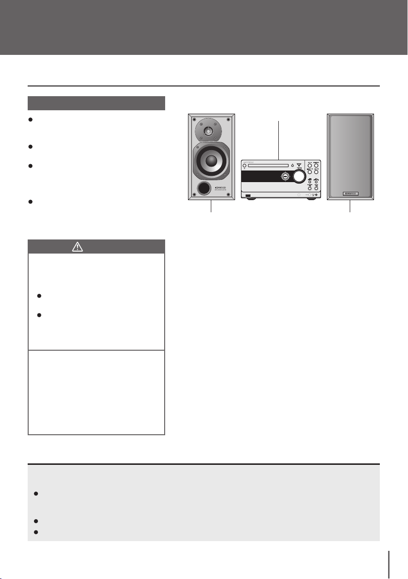
Installation
Install this system as shown below.
Installation Method
Place the left and right speakers correctly. If
they are placed in wrong locations, the left and
right audio cannot be reproduced correctly.
Place the main unit by leaving a space of at
least 1 cm from each speaker.
Always install the system on a level, stable
surface. If the system is installed on a bench
or desktop, be sure to check its stre ngth
before installation.
Th e magnetis m from the spea kers may
cause color irregularities on a nearby TV or
PC screen. Always install the speakers at a
distance from a TV or PC.
CAUTION
Ob se rve th e fo llo wing c au tio ns w hen
in sta lli ng the syst em. Ins uff ici ent heat
radiati on may buil d up intern al h eat and
cause a malfunction or fire hazard.
Do not place an object that may hinder
heat radiation on the system.
Le ave th e sp ace s sp ecif ied be low
around the cabinets of the main unit.
Top panel: 50 cm or more
Back panel: 10 cm or more
Left speaker Right speaker
Main unit
Install the system so that the power outlet is
easily accessible from the user, and unplug
th e pow er cord f rom the p ower ou tle t
immediately in case of a trouble.
Note that the power supply to the system is
not shut down completely by simply setting
the power key to OFF.
To shut down the power supply completely,
it is required to unplug the power cord.
To improve the audio effects
The audio is variable depending on how the speakers are installed. Ensure the following points to enjoy music with
higher quality.
Make the environments around the left and right speakers as equal as possible. Also reduce the sound reflections in
these environments as low as possible.
(For example, install the left and right speakers at distances from the walls and hang a thick curtain on glass windows.)
Place the left and right speakers at a large distance between each other.
Place the left and right speakers on the same height as the ears of the listener.
7
Page 8
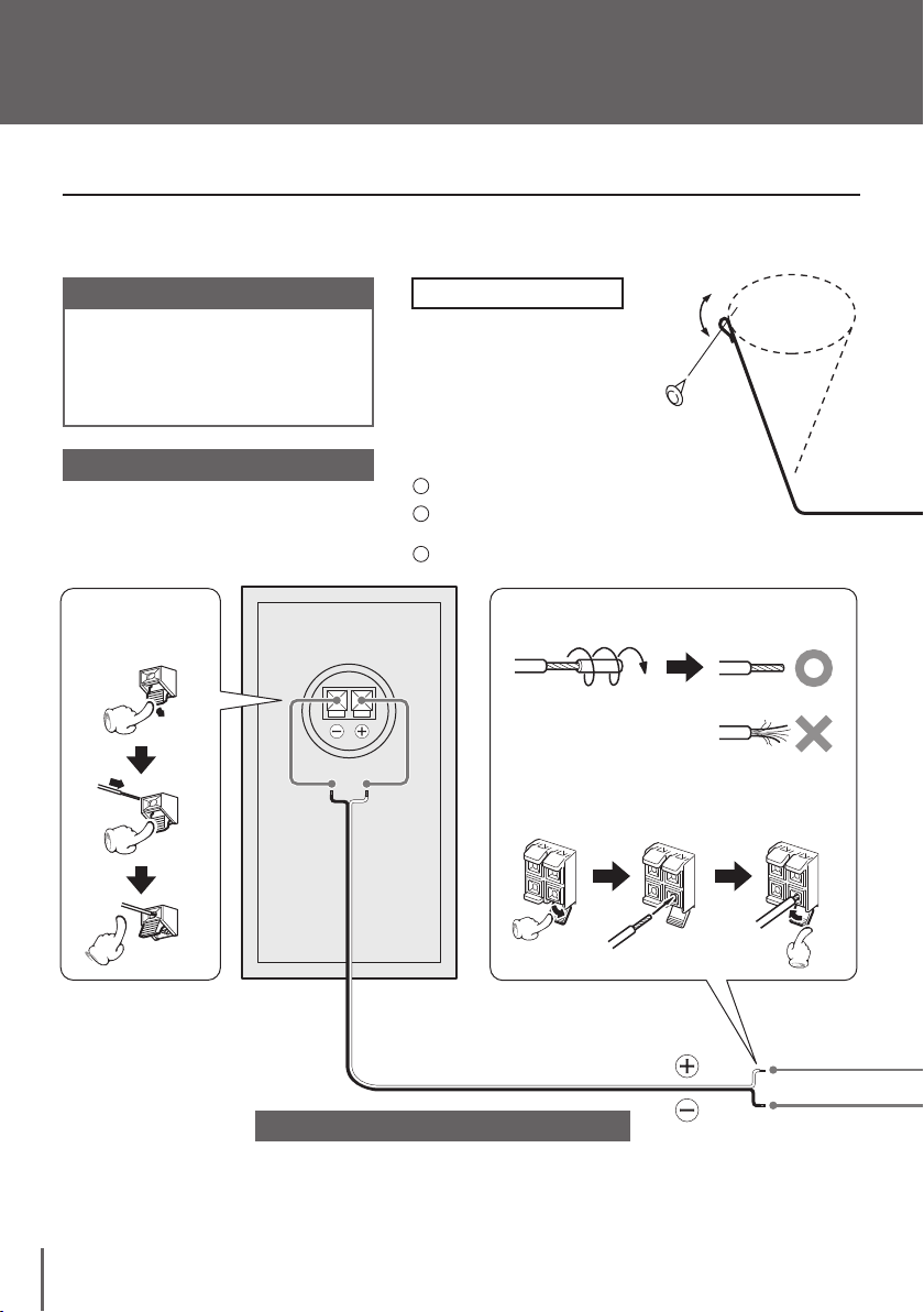
Connections
1
2
3
Connecting the main unit and accessories
Conn ec t ever y con nection c or d f ir mly .
Incomplete insertion may cause loss of a udio
output or generation of noise.
Caution for connection
Do not pl ug the power cord i nto the power
outlet until all other connections are completed.
Before unplugging a connected cord or cable, be
sure to set the power key to OFF and unplug the
power cord from the power outlet in advance.
Malfunction of microcomputer
If the system does not work properly or the display
shows wron g i nfor mati on even when corr ect
connections are made, refer to page 7 1 of the
“Operating Procedures” to take proper measure.
Connecting a speaker
cord to the speaker
FM indoor antenna
Th e pr ov ide d FM an te nna is a
si mp lifi ed o ne f or indo or u se,
in tende d for temp orary u se. To
re cei ve FM st ati ons s tab ly, it i s
recommen ded to use an o utdoor
antenna (commercially available).
Remove the simplified antenna after
connecting the outdoor antenna.
Connect the antenna to the antenna terminal.
Find the antenna locati on t hat offers best
reception.
Fix the antenna in the found location.
Treatment of the speaker cord extremities
Twist a nd re move the vinyl
co ati ng on t he ex tre mit y
of each s peaker cord. Also,
apply the same treatment to
the antenna cord extremities.
Connecting a speaker cord to the main unit
LS-K501 R
(Right speaker)
White line on transparent coating
Caution for speaker cord connection
Be careful not to short-circuit the + and – conductors of
the speaker cord.
If the speaker cord is connected by inverting the + and
– polarity, the reproduced audio will be unnatural with
unclear positioning of musical instruments.
English
8
Page 9
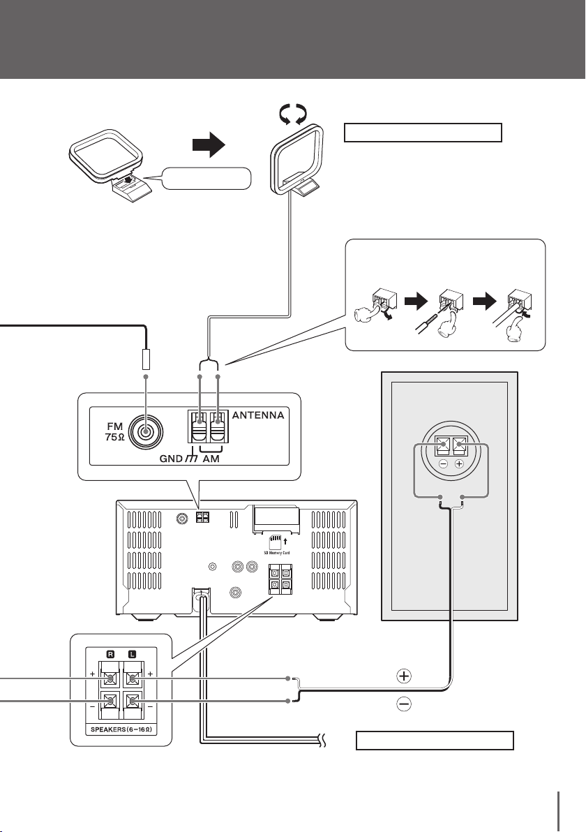
Fit into the groove.
AM loop antenna
The provided AM antenna is an indoor
antenna. Install it as apar t as possible
from the main unit, TV s et, speaker
cords and power cord and orient it in
the direction that offers best reception
condition.
Connecting a antenna cord
to the main unit
AC Power Cord
To AC wall outlet
LS-K501 L
(Left speaker)
White line on
transparent coating
Power Cord
Insert the power plug all the way into
the power outlet.
9
Page 10

Connections
Connecting Associated Products (Commercially Available)
Before connecting associated system products,
be sure to read their instruction manuals.
Connect every connection cord firmly.
Incomplete insertion may cause loss of a udio
output or generation of noise.
Caution for connection
Set the mai n uni t i n t he stan dby mode
before connecting any associated product
to it and do not set the power key to ON
until all connections are completed.
Bef ore unplu gging a conn ected cord or
cable, be sure to set the power key to OFF
and unplug the power cord from the power
outlet in advance.
USB mode
Storage
Player
* Ce r ta in m od e ls
d is pl ay th e US B
connectio n mode
selectio n menu. In
this case, select the
“Storage” mode.
Conn ect a Kenwo od di gita l
a ud io playe r ( se pa ratel y
available
C on ne ct i ng it u si ng th e
ded ic at ed ca bl e m ak es i t
possible to control it from the
mai n u nit or remo te control
unit (Refer to page 10 of the
“Operating Procedures”.)
D.AUDIO IN connector
HD20GA7 or M1GC7).
USB connector
Connect a Kenwood digital memory audio player
(separately available M1GC7) or other USB mass
storage class-compatible digital audio player.
* With certain models, it takes a certain period
before the connection is recognized.
Caution for USB connection
Do not conne ct a component other than
a US B ma ss st orag e cla ss-c ompa tib le
digital audio player to the USB connector.
Kenwood will not assume any liabilities for
the m alfunc tion, damage or loss of data
that may result from connec tion of other
kind of component.
English
10
PHONES jack
Con nect headphon es (separ atel y a vail able )
equipped with a stereo mini-plug.
Page 11

Memory card slot
Ins er t a me mo ry card (s epar atel y
available).
(Refe r t o p age 53 of the “Opera ting
Procedures”.)
FM outdoor antenna
Use a 75-Ω coaxial cabl e, lead it indoors and
connec t to the FM 75 Ω terminal. Remove the
simplified FM indoor antenna after connecting
the outdoor antenna.
Caution for outdoor antenna installation
Since antenna installation necessitates skill
and experience, always consult your dealer
bef ore inst allation. The antenn a s hould
be placed at a dis tance from the power
dist ributio n wires. Otherwise, an elec tric
shock accident may occur if the antenna
falls down.
R
L
AUX IN jacks
Co nn ec t to a ud io a utpu t of an
auxiliary component such as a VCR
or a tu rnt abl e inco rpo rat ing an
RIAA equalizer amplifier (separately
available P-110).
D.AUDIO OUT (ANALOG) jack
Connec t a d igital audio player with
direc t enco ding c apab ilit y usin g a
commercially c ord with stereo mini
plugs. Note that the D.AUDIO OUT jack
outputs an analog signal.
SUB WOOFER PRE OUT jack
Co nnect t he powered su bwoo fer
(separately available SW-40HT, etc.).
11
Page 12

Controls, Connectors and Indicators
1
2
3
4
5
6
7
8
11
13
14
15
16
9
10
12
18
19
17
20
3
5
6
7
8
9
10
11
1213
14
15
16
17
18
19
20
4
1
2
SETUP/D EMO
SETUP/D EMO
Display
English
12
Character information display
Available operation key indicators
The indicators light to indicate the MULTI CONTROL keys that
can currently be pressed for editing or selection operation.
Timer indicator (Refer to page 46 of the “Operating Procedures”.)
The indicator lights up when the timer is activated.
D.AUDIO indicator
The indicator lights when a Kenwood digital audio
player is connected through the dedicated cable.
Sound setup indicator (Refer to page 18
of the “Operating Procedures”.)
The indicator lights when the sound setup is enabled.
Music file type indicators
An i nd ica tor li ght s up a cco rdin g to the ty pe
(compression format) of the music file being played.
Source operation indicators
The indicators for the connected (inserted) audio
input source or recording condition light or blink.
REC REMAIN indicator (Refer to page 54
of the “Operating Procedures”.)
Th e in dica to r ligh ts when th e re main ing
recording time is being displayed.
Tuner and time -relate d i ndicato rs (Refe r to
pages 20 and 54 of the “Operating Procedures”.)
O.T.E. (One-Touch Edit) recording indicator (Refer
to pages 26 to 29 of the “Operating Procedures”.)
The indicator lights during O.T.E. recording.
Mode-related indicators (Refer to pages
6 to 15 of the “Operating Procedures”.)
One of the indicators light according to the selected mode.
: Repeat play mode
: Random play mode
: Folder mode
: Program mode
A.P.S. (Auto Power Save) indicator (Refer
to page 68 of the “Operating Procedures”.)
The display design mention ed in th e foll owing
text may differ from the actual design
Recording progress indicator
The indicator segments show the progress of recording.
Record mode -related indicators (Refer to
page 56 of the “Operating Procedures”.)
Th e indi cat ors li ght to i ndi cate t he mod es of
recording in the USB audio player and memory card.
MUTE indicator (See page 24.)
The indicator lights during audio muting.
Play/record/pause indicators
Record setup indicators (Refer to page 57 of
the “Operating Procedures”.)
The indicators light according to the recording speed and input settings.
RDS-related indicators (See page 24, 25.)
: Lights in SETUP or TOOL operation.
: Lights when a folder in a USB audio player or
memory card is selected.
: Lights when a music file in a USB audio player or
memory card is selected
Selection cursors
Ei th er cur sor li gh ts to in dica te the ch arac te r
information being selected.
Demonstration function
This system incorporates a demonstration function (display only). In the
demonstration mode, the lighting operation indicators vary in sequence
but this variation is accompanied with no change in played audio.
To cancel (switching demonstration off)
Press during
To start (switching demonstration on)
* The demonstration is switched on automatically when a
power failure occurs or the power cord is unplugged or
plugged in again while the system power is ON.
demonstration.
Press and hold for more than 2 seconds
while the system power is ON.
Page 13

1
2
3
4
5
16
5
6
7
8
9
10
11
12
13
14
15
Main unit
SETUP/DEMO
MULTICONTOROL
VOLUME
PHONE
MEMORYCDUSB
INPUT
SELECTOR
TUNER/BAND
CD MEMORY
O.T.E.
CD USB
O.T.E.
STOP
[AUTO/MONO]
IN
3
5
7
6
8
9
1011
12
131415
4
16
1
2
Power key (See page 25.)
Press to switch the power of the system ON/OFF
(standby mode).
Standby/timer indicator
The indicator lights when the system power is
set to the standby mode.
Red lighting: Ordinary standby mode
Amber lighting: Timer standby mode
CD tray (See page 25.)
Place a CD on the tray.
CD open/close key (See page 25.)
Press to open or close the CD tray.
SET UP/DEMO key
Press to set up the system of this unit.
(Refer to page 42 of the “Operating Procedures”.)
Press or hold to switch demonstration on/off. (See page 12.)
Play/pause keys (Refer to pages 6~ of the “Operating Procedures”.)
Press to start or let pause the playback of each audio input source.
TUNER/BAND key (Refer to page 20 of the “Operating Procedures”.)
Press to select the tuner source.
Also, press to select the radio-broadcasting band
STOP [AUTO/MONO] key
Press to stop playb ack or record ing. (Refer t o page 6~ the
“Operating Procedures”.)
Press during a setup to stop it in the middle.
When the tuner source is selected, press to select the auto or
manual tuning. (Refer to page 21 of the “Operating Procedures”.)
Press in the standby mode to dis play the current time for 5
seconds. (Refer to page 69 of the “Operating Procedures”.)
CD USB O.T.E. key
(Refer to page 26 of the “Operating Procedures”.)
Press to start O.T.E. recording of a CD.
CD MEMORY O.T.E. key
(Refer to page 28 of the “Operating Procedures”.)
Press to start O.T.E. recording of a CD.
D.AUDIO IN connector (Refer to page 10 of the
“Operating Procedures”.)
Connect a Kenwood digital audio player using
the dedicated cable.
Headphones jack (See page 10.)
Connect headphones (separately available) equipped
with a stereo mini-plug.
INPUT SELECTOR key
(Refer to pages 9 to 11 of the “Operating Procedures”.)
Press to select the source for D.AUDIO or AUX.
VOLUME control knob (See page 28.)
Pres s to adjust the listening volume . Turn ing the
knob clockwise increase the volume and turning it
counterclockwise decreases the volume.
Remote control sensor (See page 15.)
USB connector (See page 10.)
Connect a USB audio player.
MULTI CONTROL knob
Press to select music, music file or broadcasting station.
Use during playback to fast forward or fast reverse it.
Use during setting to select and enter an item.
Standby mode
When the standby/timer indicator is lit, a small amount of
power is supplied to the system to back up the memory. This
status is referred to as the standby mode. During this mode,
the system can be switched OFF from the remote control unit.
One-touch operation function
The syst em incorpo rates the conven ient on e-to uch
operation function. When the system is in standby mode,
pressing one of the keys switches the system ON. If
a disc is loaded in the selected audio input source, its
playback also starts at the same time.
13
Page 14

Controls, Connectors and Indicators
1
2
3
4
5
6
7
8
9
10
11
12
13
14
1
4
6
7
8
9
10
11
12
13
14
15
16
17
21
22
23
24
25
26
27
29
28
30
31
20
19
18
5
3
2
Remote Control unit
English
14
The ke ys having the sa me name s a s t he keys on the ma in unit
function in the same way as the main unit keys with the same times.
Power key (See page 25.)
Press to switch the power of the system ON/OFF (standby mode).
DIMMER key (Refer to page 66 of the “Operating Procedures”.)
Press to adjust the display brightness
PTY key (Refer to page 25 of the “Operating
Procedures”.)
Press to enter PTY mode.
DISPLAY/CHARAC. key (Refer to pages 38
and 54 of the “Operating Procedures”.)
Press to display a title, broadcasting station name or time.
Press during character input to switch the character group.
TIME DISP. key (Refer to pages 54 of the “Operating Procedures”.)
Press to switch the time display information.
CLEAR key (Refer to pages 25, 39 and 57 of the “Operating Procedures”.)
Press to clear a track during program play mode.
Also, press to clear a preset station.
Press during character input to clear a character.
FLAT key (Refer to page 19 of the “Operating Procedures”.)
Press to cancel temporarily the TONE, D-BASS and
MANUAL EQ setups.
Tone setting keys (Refer to page 18 of the “Operating Procedures”.)
Press to switch the TONE, D-BASS, MANUAL EQ or SPRM setup.
SET UP key (Refer to page 42~ of the “Operating Procedures”.)
Press to set up the system of this unit.
VOLUME keys (See page 24.)
Press to adjust the listening volume. Pressing the upper key increases
the volume and pressing the lower key decreases the volume.
MUTE key (See page 24.)
Press to mute the audio temporarily.
STOP [AUTO/MONO] key
Pre ss to sto p p layback or re cordi ng. (Refer to pag e 6 ~ o f the
“Operat ing Procedures”.) Press during a setup to stop it in the
middle. When the tuner source is selected, press to select the auto
or manual tuning. (Refer to page 21 of the “Operating Procedures”.)
Press in the standby mode to display the current time for 5 seconds.
(Refer to page 69 of the “Operating Procedures”.)
TUNING key (Refer to page 7 to 21 of the
“Operating Procedures”)
Press to fast forward or fast reverse music.
When the tuner source is selected, press to select a
broadcasting station.
D.AUDIO play/pause key
Press to start or let pause the playback of the Kenwood digital
audio player connected to the D.AUDIO IN connector using the
dedicated cable. (Refer to page 10 of the “Operating Procedures”.)
Page 15

29
30
15
16
17
18
19
20
21
22
23
24
25
26
27
31
28
1
2
3
30° 30°
Approx.
6m
TIMER key (Refer to page 46 of the “Operating Procedures”.)
Press to activate or deactivate the timer.
INTRO SCAN key (Refer to page 16 of the “Operating Procedures”.)
Press to start the Intro Scan of all music files or the
files in the selected folder.
P.MODE key (Refer to pages 6, 14 and 16 of
the “Operating Procedures”.)
Press to select the play mode (all-track play mode, folder
play mode or program play mode).
REPEAT ke y (Refe r t o pa ge 13 of th e
“Operating Procedures”.)
Press to start repeat playback.
RA NDOM k ey (Re fer to p age 12 o f the
“Operating Procedures”.)
Press to start random playback.
TUNER [FM/AM] key (Refer to page 20 of the “Operating Procedures”.)
Press to select FM or AM.
AUX key (Refer to page 9 of the “Operating Procedures”.)
Press to select AUX.
P.CALL key (Refer to page 7 to 20 of the “Operating Procedures”.)
Press to sk ip music. W hen the tuner source is
selected, press to select a broadcasting station.
Play/pause key (Refer to page 6~ of the “Operating Procedures”.)
Press to start or let pause the playback of each audio input source.
RETURN key
Press dur ing settin g o r e diting to return to th e
previous item or previous display page.
MULTI CONTROL keys
Press to select music, music file or broadcasting station.
Use during playback to fast forward or fast reverse it.
Use during setting to select and enter an item.
TOOL key
Press during editing.
Numeric keys/character input keys
Press to select a title. (Refer to page 7~ of the “Operating Procedures”.)
Press to input a title. (Refer to page 38 of the “Operating Procedures”.)
O.T.E. key (Refer to page 26 to 29 of the “Operating Procedures”.)
Press to start O.T.E. recording of a CD.
MEMORY USB key
(Refer to page 30 of the “Operating Procedures”.)
Press to start transfer of music files from the memory
card to the USB audio player.
MEMORY REC key
Press to start recording on the memory card.
(Refer to page 32 to 35 of the “Operating Procedures”.)
SLEEP key(Refer to page 47 of the “Operating Procedures”.)
Press to set the sleep timer.
Operation
Plug the power cord of the system to a power outlet
and press the power key on the remote control unit
to turn the system ON.
After the system is switched ON, press the desired
operation key.
The system may malfunction if the remote control
sensor is exposed to direct sunlight or the light of
a fluorescent lamp with high-frequency lighting
system (inverter system, etc.).In this case, change
the system installation to prevent malfunction.
Loading batteries in the remote control unit
When the remote control batteries are exhausted,
replace them with a pair of new R03 batteries.
Remove the battery cover
Replace the batteries with
new R03 batteries
* Insert batteries with
correct polarity.
Close the battery cover
The p rovided batter ies are intend ed for use in
checking operations and their life may be shorter
than usual.
15
Page 16

Additional Information
Media Usable With This System
Icon on this system
Kenwood Digital
Audio Player
USB
USB mass storage class-
compatible
digital audio player
SD memory card
Memory
Card
CD
SD logo is a trademark.
miniSD is a trademark of the SD Association.
miniSDTM card
Commercially available
music CD
A CD-R or CD -RW that
has b een reco rded in
the CD-DA format
TM
NoteMedium
Do not connect a component other than a USB mass storage classcompatible digital audio player to the USB connector. Kenwood will
not assume any liabilities for the malfunction, damage or loss of
data that may result from connection of other kind of component.
A memory card of 32 MB to 2 GB can be used. It is recommended to
use a memory card with 5 MB/S or more transfer speed.
A SDHC card (4 GB or more) cannot be used.
A multimedia card (MMC) cannot be used.
A special adapter is required for using a miniSDTM card.
Playback of a disc not compliant with the CD standard, such as a
copy controlled CD, is not guaranteed.
A CD-R or CD-RW that has been recorded in the CD-DA format and
finalized after recording can be played back.
Certain CD-R and CD-RW discs may not be playable on this system depending on
the equipment used for recording, the recording condition or the type of disc.
16
English
Page 17

Handling of USB Device and Memory Card (SD Card)
Handling precautions
Be sure to read the instruction manuals provided with
each USB device or memory card.
This system is not provided with a USB device and memory
card. Please purchase a commercially available product.
(See page 10.)
This system is compatible with USB 2.0. (Full speed).
It is not permitted to connect a USB device through a USB hub.
The data saved in the USB device or memory card may be
lost depending on the usage conditions. Kenwood will not
assume any liabilities for the damage incurred due to loss
of saved data.
Playable data
This syste m can play back data in the M P3 and WMA
formats.
It cannot play data recorded in the SD audio format.
MP3: Bit rate ………… 32 to 320 kbps
Sampling frequency … 8 to 48 kHz
Bit rate ………… 64 to 384 kbps (WMA9 compliant)
WMA:
Sampling frequency … 8 to 48 kHz
Recording and editing
This system records data in th e USB device or memor y
card using the WMA format.
To protect precious data…
Do not vibration the system or USB device, take out the
memor y card, dis connect the USB device or unplug
the p ower cord in the middle of recording or e diting.
Otherwise, the data in the USB device or memory device
an d the US B dev ice o r memo ry car d may b eco me
unusable.
Usable USB devices
The following restrictions are applicable to the type and
operating method of the USB device.
The US B devi ce sho uld be USB mas s stor age clas s
compatible.
For whether each USB device is compatible with the
USB mass storage class, consult its manufacturer.
The maximum current drain should be no more than
“500 mA”.
If a USB device other than specified above is used, the
music files may be unable to be played correctly. Also,
note that even a USB device complying with the above
specifications may be unable to play certain music files
depending on the type or condition of the music files.
Approximate recording capacity of USB devices and memory card
Record mode
Memory Capacity
32 MB
64 MB
128 MB
256 MB
512 MB
1 GB
2 GB
For the recording modes, refer to page 56 of the “Operating
Procedures”.
HQ
(192 kbps)
Approx. 20 minutes
Approx. 40 minutes
Approx. 1 hour 20 minutes
Approx. 2 hours 40 minutes
Approx. 5 hours 20 minutes
Approx. 10 hours 40 minutes
Approx. 21 hours 20 minutes
SQ
(128 kbps)
Approx. 30 minutes
Approx. 1 hour
Approx. 2 hours
Approx. 4 hours
Approx. 8 hours
Approx. 16 hours
Approx. 32 hours
17
Page 18

Additional Information
1
2
3
4
Handling of CD
Handling precautions
Hold a CD taking care not to touch the played surface.
Discs playable on the system
This system can play back a CD (12 cm, 8 cm), CD-R, CDRW or the audio part of a CD-EXTRA disc.
Notes on CD-R/CD-RW discs
If the CD-R or CD-RW disc in use has a printable label
surface, the disc may be unable to be taken out of the
system due to sticking of the label surface. To prevent
malfunction of the system, do not use such a disc.
Always use a disc carrying the marking.
A disc without this marking may be unable to be played
back correctly.
The disc rotates at a high speed during playback. Never
use a cracked, chipped or greatly warped disc. Otherwise,
damage or malfunction of the player may result.
Also, do not use a disc with a non-circular shape as this
may result in malfunction.
Cautions on CD discs
Memory Backup
The setups in the system are backed up for about a day even after the power cord has been unplugged from the power
outlet. The backed-up setups are as follows.
Input selection
Volume setting
Balance setting
Input level setting
D- BAS S, MA NUAL EQ a nd
SPRM function settings
Timer settings
DIMMER setting
A. P.S. (Au to P owe r Sa ve )
setting
Tuner setups Recording setups
Preset stations
Tuning mode
(Auto/manual)
Receiving band
Receiving frequency
Record mode
Recording speed
Auto marking setting
TEXT COPY setting
Recording level setting
Track mark setting
Caution for Transport or Movement
Before transporting or moving the system, prepare it as described below.
Disconnect the USB audio player and take out the memory card and CD.
Press the play/pause keys for the memory card and CD and confirm that message “NO CARD” or
“NO DISC” is displayed
Wait a while, and then turn the system OFF.
If an external component is connected, confirm that it is turned OFF and then unplug
the connection cable.
English
18
Page 19

Before Recording
×
×
×
×
Recordable and Non-Recordable Sources
Re cord ing
Recording
Source
External component
(connected to AUX)
: Digital recording possible : Analog recording in normal recording speed only × : Not possible recording
*1
Destination
USB audio player
Memory Card
CD
Kenwood digital audio
playe r c onne cted to
D.AUDIO IN
Radio
: Recording of music from the memory card to the USB audio player has the same effect as moving the music
files from the former to the latter.
USB audio player
*1
Memory card
Digital audio player
connected to D.AUDIO
OUT jack
Recording in USB Audio Player or Memory Card
Folders and music files
Every time recording of music files is started, a new folder
is created automatically in the KWD folder and the music
files are stored in the new folder. The created folder and
files are numbered automatically.
See page 20 for details.
Number of folders and music files that can be handled with the system
The maximum number of folder is 200.
A USB audio player or memory card cannot record more
than 200 folders.
The maximum number of music files is 1000
within the recording capacity.
A USB audio player or memory card cannot record more
than 1000 music files even when there is rem aining
recording capacity in it.
Copyright Information
The materials you record c anno t be us ed
without permission of their copyright owners
except for personal use.
Mater ials recorded from broadcasting, discs or other recorded
materials (music tapes, karaoke tapes, etc.) are protected by the
copy right just like the verses and melodies of songs.
The copy righ t l aw pres crib es that the permi ssio n fro m t he
copyright owners is required to sell, distribute, transfer or lend
the materials recorded from the above recorded materials or to
use them on a commercial basis (including background music in
shops, etc.).
19
Page 20

Folders and Music Files
With this system, the music data recorded in a USB audio player or memory card is
referred to as a “music file”
The music files are saved in locations called the “folders”
A folder is created every time music files are recorded in the USB audio player or
memory card to store the recorded music files in it.
.
.
When selecting a folde r or mus ic file, press the MULTI
CONTROL keys by referring to the following chart.
(They can also be selected with the MULTI CONTROL knob
on the main unit.)
KWD
Move using
left/right keys.
KWD folder
Created automatically
in the first recording
in a USB audio player
or memory card.
He rea fte r all o f the
rec orded mu sic file s
an d crea ted folde rs
are placed under the
KWD folder.
memory card
AL_A01
left/right keys.
Move using
up/down keys.
AL_A02
left/right keys.
Move using
up/down keys.
Move using
Move using
Move using
up/down keys.
Data layout in USB audio player and
TR001.WMA
TR002.WMA
TR011.WMA
TR001.WMA
TR002.WMA
TR003.WMA
TR004.WMA
AL_A01
TR001.WMA
Move using
up/down keys.
Repre sent s
a folder.
Re presents a
music file.
Select a music file
and press ,
*
it will be played.
AL_A03
* FXXX shows a music file order. It manages automatically by
the number by the order of the row of the folder and the
order of the row of a music file. Playback can be started with
any music file by selecting it with numeric keys on the remote
control unit. (Refer to page 7 of the "Operating Procedures".)
English
20
Example) To select F007:
To select F102
,
Page 21

The recorded mus ic files and folde rs accommo dating them are
numbered automatically. These number can later be modified.
Numbers assigned to folders:
AL_A01…AL_A99…
…AL_Z99
Numbers assigned to music files:
TR001.WMA,
TR002.WMA……
This system records data in the USB device or memory card using
the WMA format.
When music is recorded from this system to
USB audio player or memory card
M ax im u m n um bers of
fo ld ers a nd m usic fi le s
handled by the KWD folder
Folder …………… 200
Music files ………
For the maximum numbers
of f olders and mu sic fil es
handled by the KWD folder,
re fe r to p ag e 51 of th e
“Operating Procedures”.
1000
Example:
When a CD is recorded:
When tracks selected
fro m ano th er CD is
recorded in the same
memory card:
Track 1
Track 2
Track 11
Track 3
Track 5
Track 8
Track 9
Data layout in USB audio player and
memory card
AL_A01 folder
KWD
AL_A01
is automatically
created.
TR001.WMA
TR002.WMA
TR011.WMA
Data layout in USB audio player and
memory card
AL_A01 folder
KWD
AL_A01
AL_A02
created in previous
recording.
AL_A02 folder is
newly created.
TR001.WMA
TR002.WMA
TR003.WMA
TR004.WMA
21
Page 22

How to Use This Volume “Operating Procedures”
32 33
Recording Music from Kenwood Digital Audio
Player
1
2
3
4
1
2
5
Select the D.AUDIO source.
Prepare recording
.
Pr ep ar at io ns
Connect a Kenwood digital audio player
to the D.
AUDIO IN connector. (Refer to
page 10 of "Read Before Use".)
Make sure that t he mem ory ca rd is in
stop mode.
If is lit
,
press the
RANDO M ke y to canc el th e
random play mode.
Memory card only
To stop recording
Enter record-pause mode.
Select the music fi le to be recorded.
Let playback pause
temporarily.
Start recording.
Pr ess the ME MOR Y
REC key again to enter
record mode.
If the memory card contains a folder named AL_Z90
or higher, a message [CHECK REFRESH] is displayed
and record ing cannot be star ted. In t his case, it
is r equired to
rearran ge th e fold ers b y mea ns of
refreshing. (See page 52.)
To le t rec ord in g pau se
temporarily
* When the dedicated cable is used, the Kenwood digital
audio player ca n be controlled from the main unit or
remote control unit
.
*
Playback pauses at the beginning of the selected music le.
* If the dedicated cable is not use d for the connection,
prepare recording on the connected Kenwood digital
audio player.
Dividing music during recording
Dur ing reco rdin g f rom the TUNE R,
AUX or D.AUDIO source to a memor y
card, the recorded music file can be
divid ed in to m ultiple musi c fi les b y
manually entering a track mark (music
division mark). Each p ress of the ke y
or knob creates a new music le from
that point.
* To
r esum e reco rdin g, pre ss the
same key again. Note that a ne w
music
le is created at this time.
or
* Do not connect a USB audio player during
recording, as this will stop the recording.
* To
cha nge th e record mode setup,
see pages 56 to 61.
A me ssage [ STOP REC No C apacity]
is d isplayed. Erase th e unnece ssar
music
fi les before retrying recording
from the beginning. (See page 36.)
*
Do not switch the system OFF or apply shock or
vibration to it while [DATA WRITING] is displayed.
The m emory card sto ps and a mes sage
[DATA WRITING] is displayed.
*
If the power to the system is shut o before [DATA
WRITING] disappears, the recorded data will be lost.
When the memor y car d bec omes
full before completion of recording:
When recording completes:
* A message [Don't remove
MEMORY CARD] is scrolled
.
* If the ded icat ed cable is n ot used
for the
connection, start playback on the connected
Kenwood digital audio player.
If the audio recorded is distorted
or too lo
w
Adjust the recording level. (See page 58.)
The memory card is put
to record-pause mode.
Start playback of the Kenwood
digital audio player.
* A message [Don't remove
MEMORY CARD] is scrolled
.
Hint
Operation-target audio sources
USB audio player
connected to the
USB connector
Kenwood digital audio
player connected to the
D.AUDIO IN connector
Memory card
inserted in the
main unit
Radio
CD
Auxi liary c omponent
connected to the AUX
IN connector
Preparations before operation
* Cor re ct o per at ion may no t
be p oss ible wi thout c orrec t
preparations.
*
The section “Preparations” does not
mention how to load a CD, insert
a memory card o r connect the
system compo nents. Fo r de tails,
refer to "Connections" on page 8
or "Basic Operation" on page 24.
* Cer tain pag es show the speci fic
preparation procedures in place of
the illustration below showing the
remote control unit and main unit.
Keys for use in operation from
the remote control unit
* Certai n pages do not show
this illustration.
Keys for use in operation from
the main unit
* Certai n pages do not show
this illustration.
English
22
Page 23

4
5
Record
Recording Music from Kenwood Digital Audio Player
Start recording.
Pr ess the ME MOR Y
REC key again to enter
record mode.
If the memory card contains a folder named AL_Z90
or higher, a message [CHECK REFRESH] is displayed
and record ing cannot be star ted. In t his case, it
is r equired to
rearran ge th e fold ers b y mea ns of
refreshing. (See page 52.)
Dividing music during recording
Dur ing reco rdin g f rom the TUNE R,
AUX or D.AUDIO source to a memor y
card, the recorded music file can be
divid ed in to m ultiple musi c fi les b y
manually entering a track mark (music
division mark). Each p ress of the ke y
or knob creates a new music le from
that point.
Pres s at the poi nt you
want to divide the music
.
* The track marks can
al so b e en te re d
automatically. (See
page 59.)
A me ssage [ STOP REC No C apacity]
is d isplayed. Erase th e unnece ssar
y
music
fi les before retrying recording
from the beginning. (See page 36.)
*
Do not switch the system OFF or apply shock or
vibration to it while [DATA WRITING] is displayed.
The m emory card sto ps and a mes sage
[DATA WRITING] is displayed.
*
If the power to the system is shut o before [DATA
WRITING] disappears, the recorded data will be lost.
When the memor y car d bec omes
full before completion of recording:
When recording completes:
* A message [Don't remove
MEMORY CARD] is scrolled
.
* If the ded icat ed cable is n ot used
for the
connection, start playback on the connected
Kenwood digital audio player.
If the audio recorded is distorted
or too lo
w
Adjust the recording level. (See page 58.)
Start playback of the Kenwood
digital audio player.
Hint
These are the operating procedures.
Indicat es a ste p usi ng the
rem ote con trol un it. Pre ss
the remote control unit keys
to perform this operation.
Indicates a step using the
main unit. Press the main
unit keys to perform this
operation.
* Steps with which both and are shown can be performed
using either the remote control unit or main unit.
Display during or after each
Th e tex t re prese nts the cha rac ters
displayed as the character information
on the display by enclosing them in [ ].
Example: Select [INTRO SCAN].
* The display illustrations in this manual
have been drawn exclusively for use
in explanation. They may differ from
the actual views of the display.
Supplementary tips on
operation
operations
Items and operations related
to the above operation
23
Page 24

Basic Operation
1
2
3
Preparations
Install the system in a proper location.
(See page 7.)
Check the connections.
(See pages 8 to 11.)
Prepare the remote control unit.
(See page 15.)
Inserting a memory card
* Be s ure to set the system to the
st andb y mode i n advance . For
detai ls, refer to page 53 of the
“Operating Procedures”.
Press the bottom edge of the
memory card slot to open the
cover.
Insert a memory card.
Close the memory card slot
cover.
Be careful of orientation!
Hold and insert the card
so that the labeled side
faces down and the cut
corner comes on the left.
1 2
3
Adjusting the volume
Increases
volume
Decreases
volume
Adjust in the range from 0 to 40 (max.).
* Turning the knob quickly (on the main unit) or
holding a key depressed (on the remote control
unit) accelerates the volume variation speed.
Decreas es
volume
3
Muting the audio temporarily
Increases
volume
To cancel muting
Press the MUTE key again
(t o return to the pre vio us vol ume
level).
Adjust the volume.
English
24
Page 25

Turn the system ON (OFF).
1
2
3
USB
1
Load a disc.
2
Open the tray.
Place a CD on the tray.
Close the tray.
* Pressing the play/pause key of the desired audio
input sourc e al so t urns the syste m ON (Onetouch operation function). (See page 13.)
* Pressing the power key while the system is ON
switches it OFF (standby mode).
Press the CD
open/close key.
Place a CD with label
side up.
Play music.
3
Press the play/pause
key of the desired audio
source.
* Fo r deta ils , refe r to the
description on playback of
each aud io sourc e i n t he
“Operating Procedures”.
25
Page 26

Care and Storage
Care and storage of main unit
Do not place in the following locations.
Place exposed to direct sunlight.
Place subjected to excessive humidity or dirt.
Place exposed to direct heat from heating equipment.
Be careful against condensation
Whe n the difference i n temperatures betw een the
main unit and the environmental air is large, dew may
be condensed inside the main u nit and may cause
malfunction of the main unit. If this happens, leave the
main unit for a few hours until its internal mechanisms
are dried up.
Take special care against condensation when the main
unit is moved between places with a large temperature
difference or into a room with high humidity.
When a main unit becomes dirty
When the front panel or case gets dirty, wipe with a soft
dry cloth. Do not use lacquer thinner, benzine, alcohol
or contact revitalizer for t hese chemicals will cause
discoloration or deformation.
Care and storage of CD
Before storing the CD
When the main unit is not to be used for a long period,
take out the CD and store in the case.
When a CD becomes dirty
When a disc is contam inated with fingerprints or
other stains, wipe gently in the radial direction using
a soft dry cloth.
Do not use an analog disk cleaner, lacquer thinner,
benzine or alcohol.
Do not use a disc accessory (stabilizer, protective
sheet, protective ring, etc.) or lens cleaner.
Other cautions
Do no t write le tter s on a CD us ing a pen cil or
ballpoint pen.
Do not use a CD if the sticker or label on it is peeled
off or bond is overflowed around the sticker or label.
Do not stick a sheet of paper, sticker or label on a CD.
Care and storage of SD card
Before storing the SD card
Always store the SD card in its case.
Avo id lo cati ons wit h a ver y hig h temp era ture
(such as a place exposed to direct sunlight) or high
humidity.
When a SD card becomes dirty
Wipe gently with a soft, dry cloth.
Do not use lacquer thinner, benzine or alcohol.
Other cautions
Do not attempt to open or modify a card.
Do not peel off the label from the card.
Do not attach a label or sticker on the card.
Do not touch the metallic terminals on the back side
with a hand or metallic object.
Caution for disposal/transfer of memory card
“Initia liza tion” o r “delet ion” of the card usi ng this
system or a PC simply modifies the file management
in for mat ion a nd do es no t era se th e dat a in the
memor y card completely. Before disposal or transfer
of a memory card, it is recommended to destroy the
memory c ard physi cally or to d estroy the data in it
completely by u sing commercially available PC data
destruction software.
The data in the memory card should be managed on
the user’s own responsibility.
Care and storage of USB device
Be sure to read the instruction manuals provided with
each USB device.
English
26
Page 27

Specifications
Main unit (RD-K501USB)
[Amplifier block]
Effective output power during STEREO operation (1 kHz,
10%, T.H.D., at 6 Ω)
..................................................................................20 W + 20 W (RMS)
Total harmonic distortion .....................................................0.025%
D-BASS (+10) ............................................... +9.0 dB (60 Hz, Vol. 30)
Input (Sensitivity/impedance)
LINE (AUX) .......................
LINE (D. AUDIO) ............
Output (Level/Impedance)
PRE OUT (D. AUDIO) ...................................900 mV/10 kΩ (HIGH)
..............................................................................550 mV/10 kΩ (LOW)
SUB WOOFER PREOUT ................................................... 1.6 V/10 kΩ
(1 kHz, 10 W, 6 Ω, 30 kHz LPF)
350 mV / 22 kΩ (Max INPUT LEVEL)
350 mV / 10 kΩ (Max INPUT LEVEL)
[CD player block]
Laser ................................................................... Semiconductor laser
D/A converter ..................................................................................1 bit
Oversampling .............................................................8 fs (352.8 kHz)
Frequency response .................................................. 20 Hz~20 kHz
Wow & flutter ............................................
Below measurable limit
[Tuner block]
FM tuner
Tuning frequency range ...........................
AM tuner
Tuning frequency range ...........................
87.5 MHz~108 MHz
531 kHz~1,602 kHz
[USB block]
Usable USB device ......................................USB Mass strage class
Interface ...................... USB 2.0 (Full speed) USB 1.1 compatible
File system .....................................................................
Recording format
WMA SQ ......................................128 kbps/44.1 kHz STEREO
HQ .....................................
Playing format
MP3 Sampling frequency .....................................
Bit rate (CBR/VBR *) ................................
WMA (WMA9
Sampling frequency .....................................
Bit rate (CBR/VBR *) ................................
ID3 tag ..............................................................Non-correspondence
Maximum numbers of folders ....................................................200
Maximum folder hierarchical number ....................................... 10
Maximum numbers of files .......................................................
Maximum current drain ........................................................
compliant, DRM non-correspondence)
192 kbps/44.1 kHz STEREO
FAT 12/16/32
8~48 kHz
32~320 kbps
8~48 kHz
64~384 kbps
1000
500 mA
[Memory card block]
Usable memory card .............. SD memory card, miniSDTM card
Usable memory card capacity ...................................32 MB~2 GB
File system .....................................................................
Recording format
WMA SQ ......................................128 kbps/44.1 kHz STEREO
HQ .....................................
Playing format
MP3 Sampling frequency .....................................
Bit rate (CBR/VBR *) ................................
WMA (WMA9
Sampling frequency .....................................
Bit rate (CBR/VBR *) ................................
ID3 tag ..............................................................Non-correspondence
Maximum numbers of folders ....................................................200
Maximum folder hierarchical number ....................................... 10
Maximum numbers of files .......................................................
* The audio data of VB R may be come beyond the limits
of the bit rate the above- mention ed, and may n ot be
playable on this system.
compliant, DRM non-correspondence)
192 kbps/44.1 kHz STEREO
FAT 12/16/32
8~48 kHz
32~320 kbps
8~48 kHz
64~384 kbps
1000
[Power supply and other blocks]
Power consumption .....................................................................73 W
Standby power consumption .................................... 0.4 W or less
Dimensions ............................................... Width 240 mm (9-7/16")
Height 121.5 mm (4-13/16")
Depth 361 mm (14-3/16")
Weight (net) .................................................................5.3 kg (11.7 lb)
Speakers (LS-K501)
Enclosure ............................................................. Bass-Refrex system
Speaker unit configuration
Woofer .............................................................
Tweeter .........................................
Impedance .......................................................................................... 6 Ω
Power handling capacity ............................................................20 W
Dimensions ................................................. Width 140 mm (5-1/2")
Height 260 mm (10-1/4")
Depth 209 mm (8-1/4")
Weight (net) .....................................................2.2 kg (4.9 lb) (1 pcs)
Design and specifications are subject to change without
notice.
Full pe rformance is not guaranteed in extremely cold
environments (under water-freezing temperatures).
100 mm cone type
25 mm balanced dome type
For your records
Record the serial number, found on the back of the unit, in the
spaces designated on the warranty card, and in the space provided
below. Refer to the model and serial numbers whenever you call
upon your dealer for information or service on this product.
Model
Serial Number
27
Page 28

28
English
 Loading...