

Page 1
(to the next page)
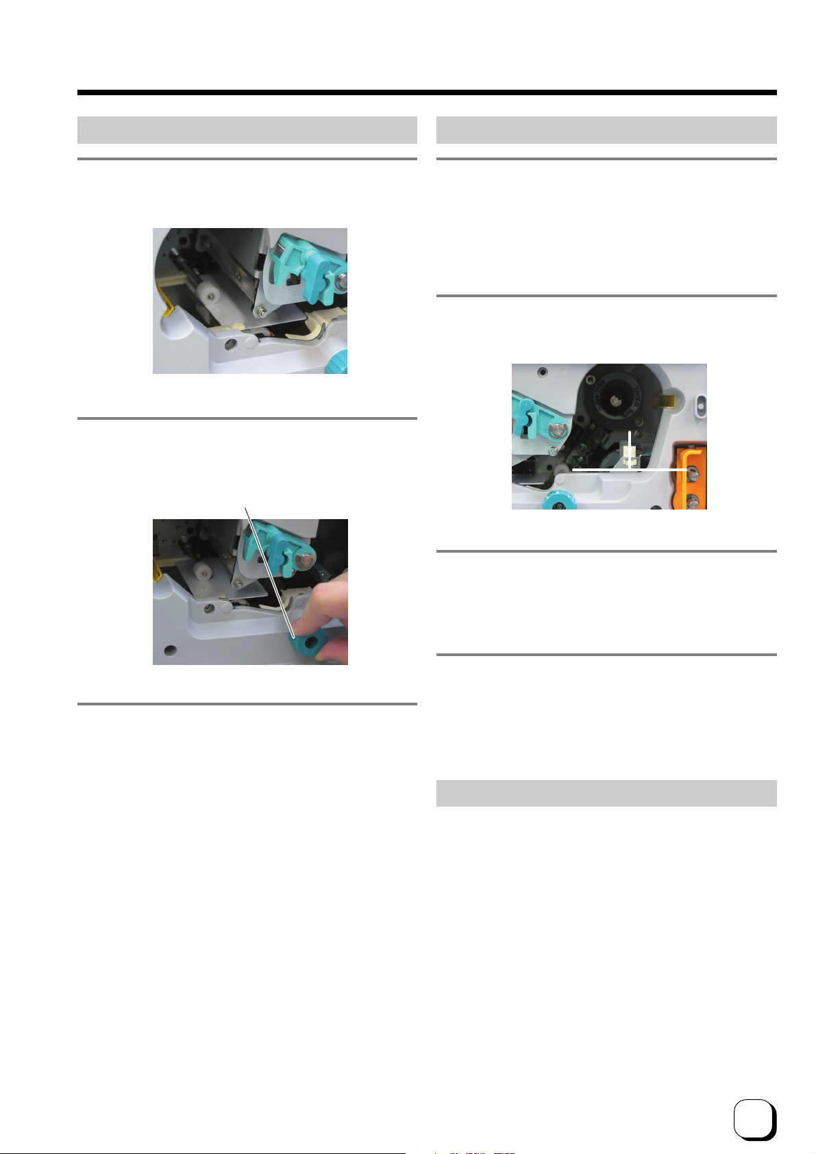
B. When card is at the left (near printing unit)
1.
Adjust the direction of the tilted card with your
hand such that it is parallel with the card guide.
2.
Turn the knob of the card transfer in the anticlockwise direction to transfer card to the
stacker.
Card Transfer Knob
C. When card can barely be seen from the encoding unit
1.
Open the jog cover behind the card cassette, turn
the jog dial in the anti-clockwise (upward)
direction to move card into the encoder. Refer
to Feed Jam (page 29 of this manual) on how to
open the jog cover.
2.
If the inverter is not vertical, turn it to a vertical
position with your hand.
3.
Install the ink cassette and close the printer door.
Refer to pages 13 and 14 of this manual.
Printer will start to initialize and return to the Ready mode.
3.
Turn the jog dial clockwise (down) to move card
from the encoding unit to the inverter, followed
by removing it with your hand.
4.
Install the ink cassette and close the printer door.
Refer to pages 13 and 14 of this manual.
Printer will start to initialize and return to the Ready
mode.
Jam Inside Laminator
Refer to the instruction manual of the laminating unit
on procedures to remove the jammed card.
31
Page 2
Troubleshooting (continued)
Procedures for Changing Thermal Head
CAUTION
discharged to the thermal head may cause it to break
down. Before exchange, touch metal parts of the printer
such as the screw to release the static electricity.
Do not touch the heating unit of the thermal head with
your hand. If you have done so, follow procedures on
the page 25 of this manual to perform cleaning upon
changing the thermal head.
Carry out the work carefully and avoid knocking the
heating unit of the thermal head against any hard object.
Ensure that printer is switched off before changing.
Do not loosen or remove any screws for which
instructions are not given in the procedures.
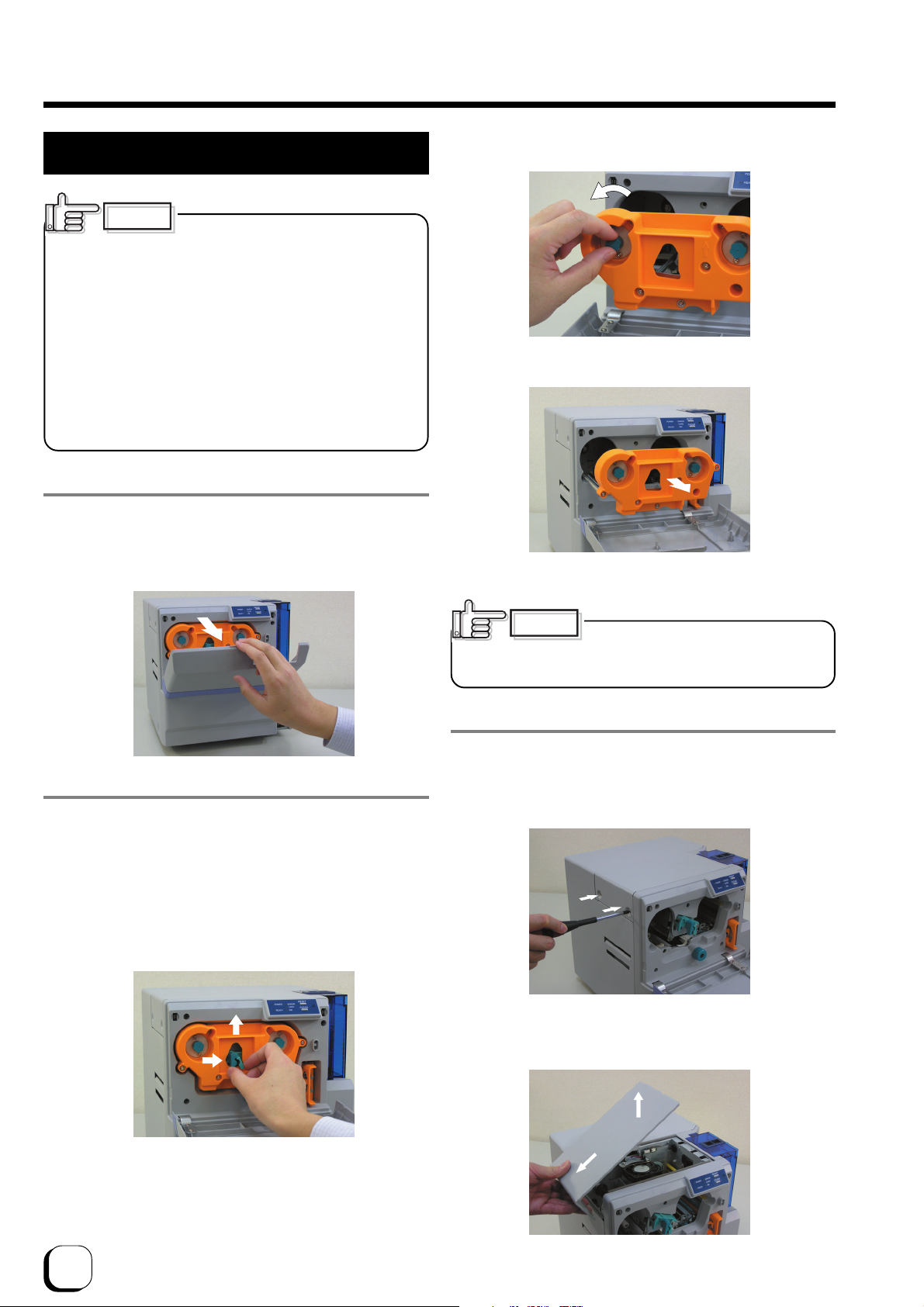
1.
Place your fingers on top of the door and open
by pulling it towards you.
Open slowly while supporting it with your hands.
Static electricity in our bodies
Remove sag
Eject cassette
CAUTION
careful not to drop the ink ribbon into the interior of the
printer when removing the cassette.
When the ink ribbon is installed, be
2.
Remove ink ribbon cassette
Hold the lock lever with your fingers and lift it to unlock.
When ink ribbon is installed, pull out the cassette by about
3cm and turn the knob on the cassette in the direction
indicated by the arrow to tighten the ribbon sag.
Remove the cassette while supporting it with both hands.
Stand cassette on a flat and firm surface.
2
1
Unlock
3.
Open the door for head exchange
Remove the 2 fastening screws on the left of the printer’s
head exchange door using a – (flathead) driver.
Slide the head exchange door to the left and remove by
lifting it up.
2
1
32
Page 3
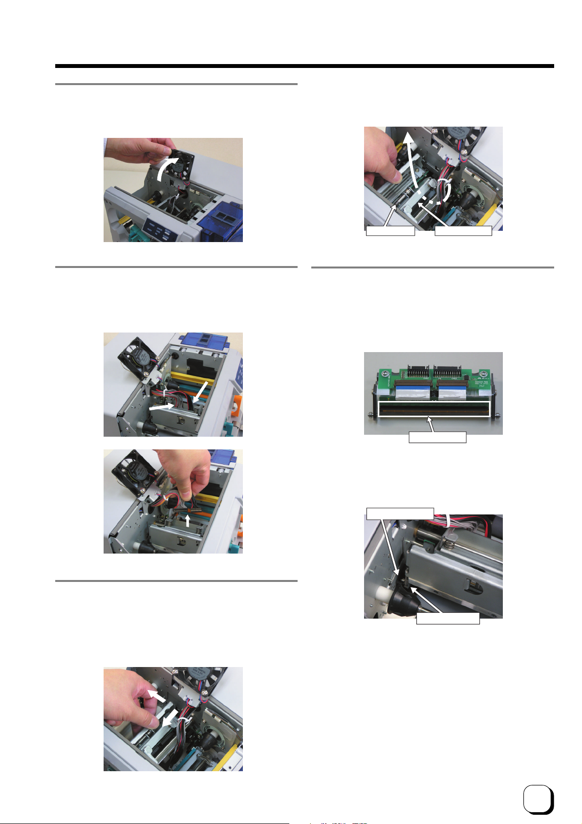
4.
Move the head cooling fan.
Lift towards you and lean it backwards.
5.
Remove head cables A and B.
Hold the part of cable that is directly above the connector
and remove by lifting them up carefully one by one.
(to the next page)
View from the top
Head shaft Head bracket
7.
Install a new thermal head
Be careful not to hit the heating element of the thermal
head against any hard object.
Reverse steps in 6. to install the thermal head while paying
attention not to catch the head cable.
B
A
6.
Remove the thermal head.
To remove the thermal head from the shaft, hold and move
it to the left while pulling forward.
Lift it up while leading it through from underneath the
head bracket.
Heating Unit
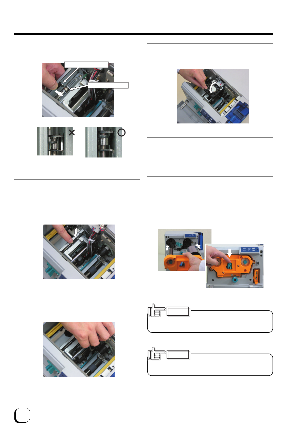
Check if the guide bearing of the thermal slot is inside
the guiding slot.
Guiding Groove
Guide Bearing
2
1
33
Page 4
Troubleshooting (continued)
Push the fastening bearing at the head fastening unit
forward and insert to the right to lock it securely.
Head Fastening Unit
Fastening Bearing
9.
Return the head cooling fan to its original
position.
8.
Insert head cables A and B.
Press the head down slowly so that the cables can be
easily inserted.
A click sound will be heard, indicating that the cassette
is locked.
10.
Mount the head exchange door by reversing the steps in
3.
11.
Unlock the cassette again. Refer to step 1.
While making sure that the ink ribbon does not sag, push
the cassette all the way in along the guide rail and lower
the lock lever to lock the cassette.
Mount the head exchange door
and fasten the 2 screws securely.
Insert cassette against the guide rail.
Hold the part that is directly above the cable connector
and insert them slowly and securely one by one.
34
CAUTION
ribbon and uneven color caused by wrinkles when the
cassette is attached.
CAUTION
the guide shaft is not properly placed in the guide rail
may damage the device.
Ribbon sags will result in jammed ink
Inserting the cassette by force when
Page 5
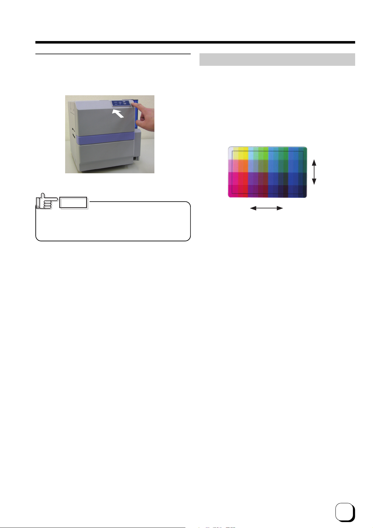
12.
Shut the printer door tightly by pressing on the top right
section of the door indicated by the word “PUSH”.
Close printer door.
Checking After Changing Thermal Head
After changing the thermal head, confirm print
position by carrying out test print using color ink
ribbons.
To perform a test print, press the Reset and Clean
buttons on the control panel simultaneously for more
than 1 second when the Ready LED is lit.
A test pattern will be printed. Ensure that margins
around the card are almost equal (approximately 0.2
~ 0.3 mm) on the top, bottom, left and right.
To p
Bottom
CAUTION
in such a way that it cannot be closed properly when
the ink ribbon cassette is not locked or when the
cassette is not inserted. Closing the door by force in
such a case may damage the device.
To prevent damage, the door is made
Left Right
Direction of test pattern: Yellow on the top left
Adjust the printer setting function on the status
monitor if the margin is not equal. Procedures for
using the status monitor can be found in the
instruction manual (electronic manual).
The density of print may change slightly before and
after changing the thermal head. Slight adjustment
of the density can be carried out using the printer
setting function on the status monitor.
Procedure for changing thermal head is now complete.
35
Page 6

Consumable/Optional Items
Consult your dealer for additional purchase of consumables, optional items and the Card Hopper for use
with the various types of cards.
Consumable Items
• Cleaning Card (for cleaning roller)
Part No. CX-120-CC1 (10 pieces)
• Cleaning Kit
Part No. CX210-CKIT1
Content
Alcohol (50 ml)
MG Cleaning Card (5 pieces)
Cotton Swab (10 pieces)
Kimwipe (1 box)
• Cleaning Unit
Part No. CX-120-CL-001
• Thermal Head
Part No. CX-120-HD-001
Optional Items
• Ink Ribbon
YMCKO 750 screen pages, Part No. CY-15C-75
YMCKOK 600 screen pages, Part No. CY-16K-60
• Card Cassette
Part No. CX-120-HP-001
• Laminator Unit
Model Name CL-50
• Hand Gloves
Model No. U105-M for size M
Model No. U105-L for size L
Microsoft, Windows is a registered trademark of Microsoft Corporation U.S.A. in United States of America and other
countries.
In this book, the names for Microsoft®WindowsXP® operating system Japanese Edition and Microsoft®Windows
2000 operating system Japanese Edition are written as Windows XP and Windows 2000 respectively
36
®
Page 7
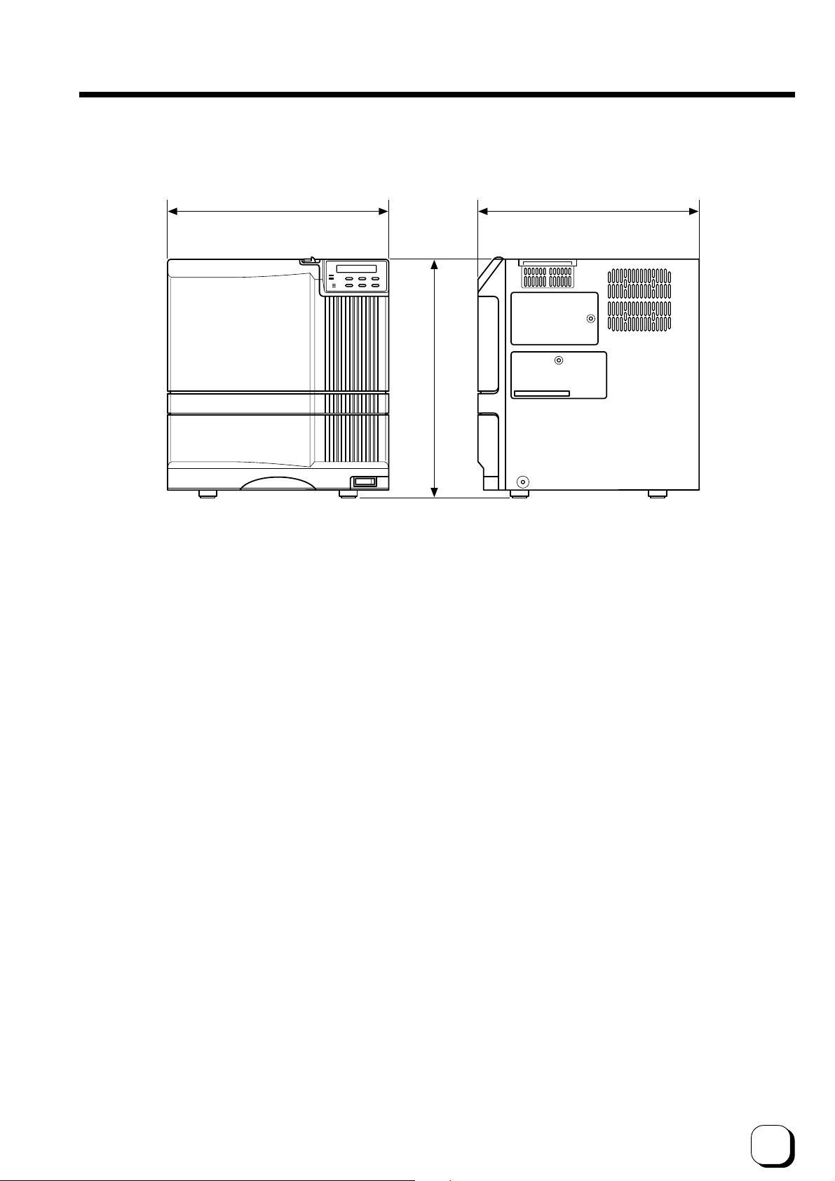
External appearance and dimensions
343
Front view
347
381
Side view
unit/mm
37
Page 8

MEMO
38
Page 9

Direct Dye Sublimation Printer CX-120 Startup Guide
Victor Data Systems Company of Japan, Ltd.
2969-2 Ishikawa-cho, Hachioji-shi, Tokyo, Japan
C
2005 Victor Company of Japan, Limited
KAT-T
0503(VP)
 Loading...