

Page 1

MICRO HI-FI COMPONENT SYSTEM
TEXT
AP
HM-582MD
INSTRUCTION MANUAL
KENWOOD CORPORATION
Before installation, be sure to read “System configuration” and “Installation” in this manual to ensure correct installation. 6
COMPACT
DIGITAL AUDIO
TEXT
B60-4705-00 00 CH (T)
0001
Page 2
Contents
2
Before applying power
Units are designed for operation as follows.
Europe and U.K. ........................................................... AC 230 V only
For the United Kingdom
Factory fitted moulded mains plug
1. The mains plug contains a fuse. For replacement, use only
a 13-Amp ASTA-approved (BS1362) fuse.
2. The fuse cover must be refitted when replacing the fuse in
the moulded plug.
3. Do not cut off the mains plug from this equipment. If the
Preparation section
plug fitted is not suitable for the power points in your home
or the cable is too short to reach a power point, then obtain
an appropriate safety approved extension lead or adapter,
or consult your dealer.
If nonetheless the mains plug is cut off, remove the fuse
and dispose of the plug immediately, to avoid a possible
shock hazard by inadvertent connection to the mains supply.
Caution : Read this page carefully to ensure safe operation.
IMPORTANT: The wires in the mains lead are coloured in
accordance with the following code:
Blue : Neutral
Brown : Live
Do not connect those leads to the earth terminal of a threepin plug.
Introduction
Safety precautions
Basic section
WARNING : TO PREVENT FIRE OR ELECTRIC SHOCK, DO NOT EXPOSE
THIS APPLIANCE TO RAIN OR MOISTURE.
CAUTION: TO REDUCE THE RISK OF ELECTRIC SHOCK, DO NOT REMOVE
COVER (OR BACK). NO USER-SERVICEABLE PARTS INSIDE. REFER SERVICING TO QUALIFIED SERVICE PERSONNEL.
RISK OF ELECTRIC SHOCK
Apprication section
CAUTION
DO NOT OPEN
THE LIGHTNING FLASH WITH ARROWHEAD SYMBOL, WITHIN AN EQUILATERAL TRIANGLE,
IS INTENDED TO ALERT THE USER TO THE PRESENCE OF UNINSULATED “DANGEROUS
VOLTAGE” WITHIN THE PRODUCT’S ENCLOSURE THAT MAY BE OF SUFFICIENT MAGNITUDE TO CONSTITUTE A RISK OF ELECTRIC SHOCK TO PERSONS.
THE EXCLAMATION POINT WITHIN AN EQUILATERAL TRIANGLE IS INTENDED TO ALERT
THE USER TO THE PRESENCE OF IMPORTANT OPERATING AND MAINTENANCE (SERVICING) INSTRUCTIONS IN THE LITERATURE ACCOMPANYING THE APPLIANCE.
The marking of products using lasers
The marking is located on the rear panel and says that the component uses laser beams that have been classified as Class 1. It
means that the unit is utilizing laser beams that are of a weaker
Knowledge section
class. There is no danger of hazardous radiation outside the unit.
CLASS 1
LASER PRODUCT
CAUTION
INVISIBLE LASER RADIATION
WHEN OPEN. AVOID EXPOSURE
TO BEAM.
Inside of this laser product, a component (a laser diode: Wavelength: 760-800nm) classified as Class 3A laser radiation is contained as alerted by the internal caution label shown above. To
avoid exposure to laser beams, do not open the cover.
Page 3
Contents
Introduction
Special features
❑
Layout free
The system components can be installed vertically on the sides (lengthwise) as well as the
conventional, horizontally stacked installation.
Try various layouts of the main unit and speakers and find that match your listening room.
❑
CD =MD high-speed (2x-speed) dubbing
A convenient feature enabling dubbing from CD to MD with simple operation and short period.
(Single CD track dubbing is newly available in addition to the all-track dubbing.)
❑
Frosty door with interior design considerations
The main unit is provided with a storable door, a feature that cannot be found in previous stereo
systems. The door does not only protect the system from damage and dirt but also suits the
interior of many listening rooms.
❑
Low standby power consumption
The power consumption during standby is no more than 2 W.
Introduction
3
Preparation section
Basic section
❑
LCD (Liquid Crystal Display) with backlit illumination
A high-definition graphic display on each component shows the operating modes such as CD
playback and tuner reception conditions at a glance. The display orientation can be changed
according to whether the system components are installed vertically or stacked horizontally.
❑
CD-TEXT data display
When discs conforming to CD-TEXT are played with this unit, the text information recorded on the
CD (disc name or titles) is displayed automatically. Some CDs conforming to CD-TEXT may not
display text information.
❑
R.D.S. (Radio Data System)
The RDS data included in FM broadcasts can be used to search for the intended broadcasting
contents and for automatic reception from standby.
❑
Convenient timer functions
1 O.T.T. timer :
When the set time comes, a source starts to play automatically only for an hour.
2 Program timer for playback (AI timer playback) and timer recording:
Two timer programs (PROG.1 and PROG.2) are available for each of the timer playback (AI timer
playback) and timer recording functions. (When playback is started with the AI timer, the
volume increases automatically until the specified level.)
3 Sleep timer :
When the set time comes, the power of the system is set automatically to OFF (standby). This
is convenient for example when you want to fall asleep while listening to music.
Application section
Knowledge section
❑
Sampling rate converter built in
The unit incorporates a sampling rate converter to handle different kinds of digital sources (32kHz,
44.1kHz, 48kHz).
Page 4

4
Introduction
Contents
Preparation section
Before applying power................................ 2
Safety precautions ............................................................... 2
Introduction ........................................................ 3
Special features .......................................................................... 3
Front door ...................................................................................... 5
Installation.......................................................... 6
Preparation section
System connection........................................... 7
1. Connection of the System Accessories............................ 7
2. Connection of Other Accessories
(Commercially Available Parts) ......................................... 9
Controls and indicators ................................. 10
Main unit .................................................................................... 10
Remote control unit ................................................................. 12
Operation of remote control unit ........................................... 13
Display ........................................................................................ 14
Clock adjustment............................................ 15
Menu mode ...................................................... 16
Basic section
Operation in menu mode .......................................................... 16
Caution : Read the pages marked
MD Edit Functions .......................................... 47
Selecting the editing function type ...................................... 47
Reordering several tracks at a time (QUICK MOVE) .......... 48
Moving the order of the track being played in a disc
(MOVE) ......................................................................................... 50
Dividing a track during playback (DIVIDE) ......................... 52
Combining tracks during playback (COMBINE) ................ 54
Erasing several tracks at a time (QUICK ERASE)................ 56
Erasing a single track during playback (ERASE)................ 58
Erasing all tracks on a disc (ALL ERASE) ............................. 59
Assigning a title to a disc or track ....................................... 60
Copying titles in title memos for use as titles
of other MDs or tracks(TITLE COPY)(TITLE MEMO)...... 65
To delete the edited contents (EDIT CANCEL) .................... 68
Listening to an AUX input source ................. 70
Timer operation............................................... 71
Setting the O.T.T. timer ............................................................ 71
Program timer playback (AI timer playback)
and timer recording .............................................................. 72
Sleep timer ................................................................................ 75
carefully to ensure safe operation.
Basic section
Hearing sound ................................................. 18
Playback of CD................................................ 20
Playback of MD ............................................... 23
Searching a desired track by its title (TITLE SEARCH) ..... 25
Receiving broadcast station ......................... 26
Using R.D.S.
Searching for a desired program type (PTY search) ......... 30
Recording on MD............................................. 32
Apprication section
(Radio Data System) .....................................
Application section
Various CD/MD playback features .............. 38
Listening in the desired sequence (program playback) .. 38
Repeated playback .................................................................. 40
Playing tracks in a random order (random playback) ...... 41
Convenient Recording Methods .................. 42
Selection of the Recording type ............................................. 42
High-speed recording of all tracks in a CD ......................... 43
High-speed recording of a single track in a CD ................. 44
One-touch recording ................................................................ 45
Knowledge section
Program recording .................................................................... 46
Knowledge section
Important Items ............................................... 76
Maintenance ............................................................................. 76
Reference ................................................................................... 77
Handling of discs...................................................................... 78
Handling of Mini disc .............................................................. 78
In case of difficulty ........................................ 79
29
Specifications ................................................. 83
Page 5
Contents
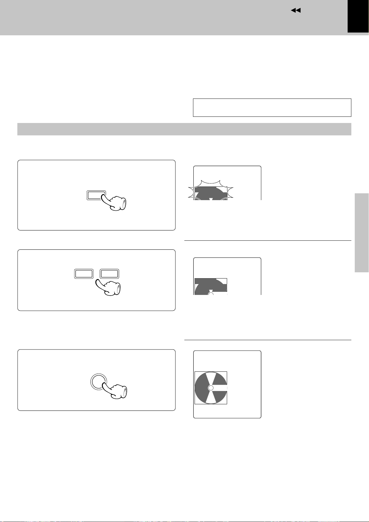
Front door
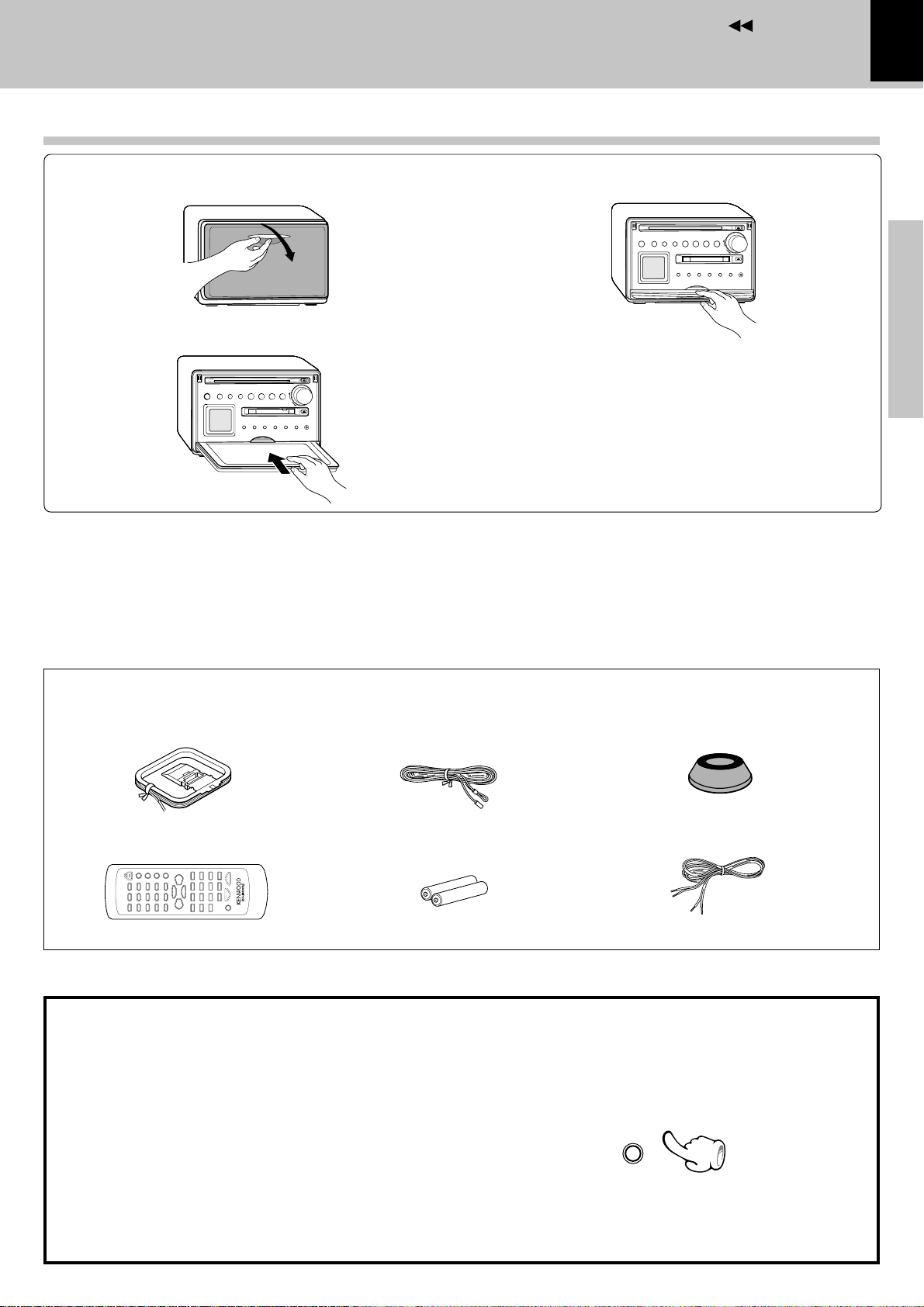
1 Open the front door.
2 Store the door by sliding in.
Introduction
5
3 Lock.
Preparation section
÷ Push in the door until it clicks.
÷ To close the door, unlock it by pushing it slightly and reverse
the above procedure.
Unpacking
Unpack the unit carefully and make sure that all accessories are put aside so they will not be lost.
Examine the unit for any possibility of shipping damage. If your unit is damaged or fails to operate, notify your dealer immediately. If your unit was shipped
to you directly, notify the shipping company without delay. Only the consignee (the person or company receiving the unit) can file a claim against the
carrier for shipping damage.
We recommend that you retain the original carton and packing materials for use should you transport or ship the unit in the future.
Keep this manual handy for future reference.
Accessories
AM loop antenna (1)
Remote control unit (1)
FM indoor antenna (1)
Batteries (R6/AA) (2)
Feet for speaker (8)
Speaker cord (2)
Basic section
Application section
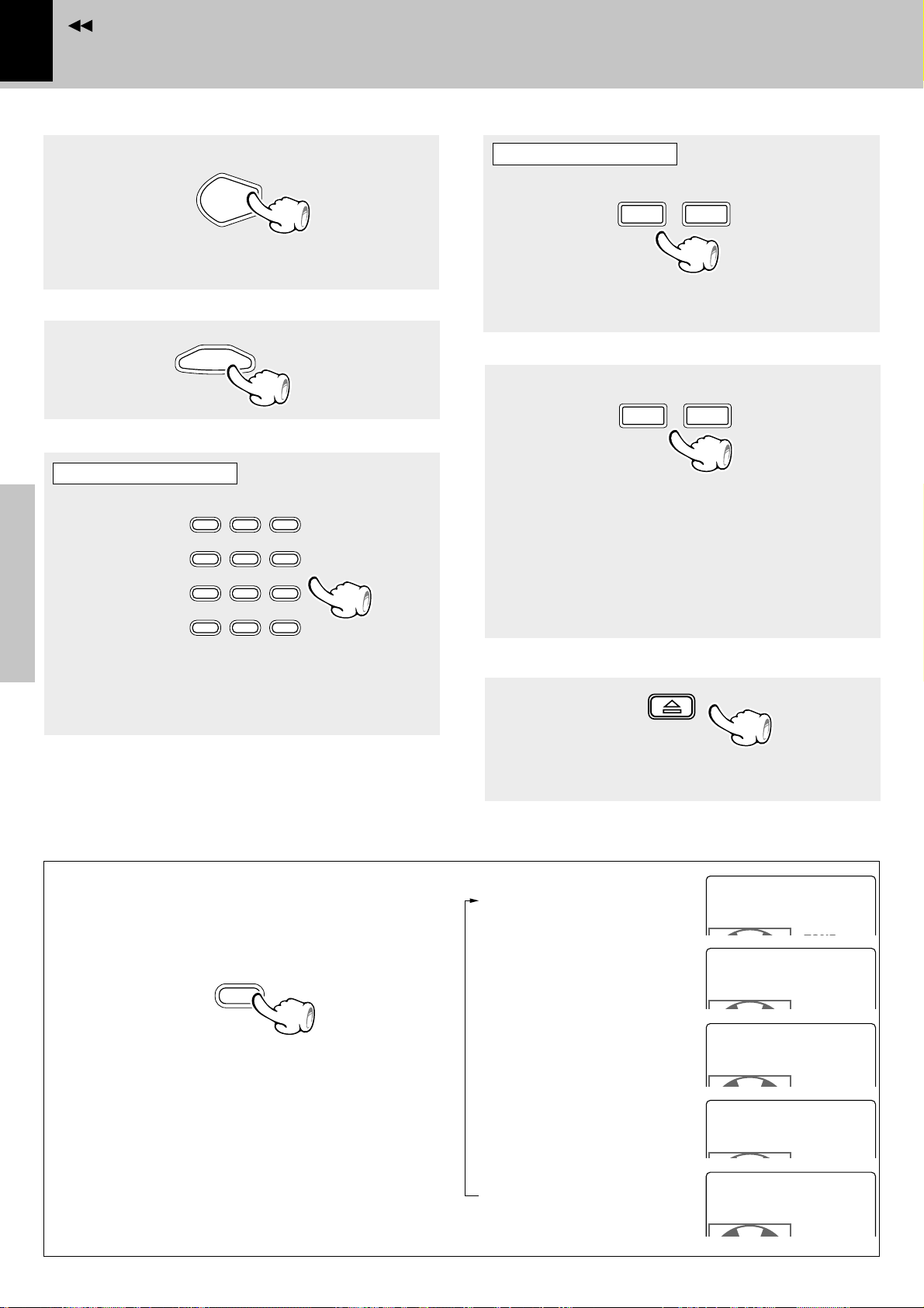
Demonstration
The demonstration consists of sequential switching
of display for showing the functions available with
the system.
The audio does not change while the demonstration
is active.
Demonstration cannot be started during playback
(or recording) of a source.
÷ Provided that the power is set to ON, demonstration is
switched automatically to “DEMO ON” after there is a
power failure or the power cord is unplugged then plugged
in again.
DEMO ON (Demonstration executed):
Knowledge section
While the power is set to ON , press and hold the
menu/demo key on the main unit for more than 2
seconds.
menu
/demo
DEMO OFF (Demonstration cancelled):
÷ Press the menu/demo key in the “DEMO ON” mode.
Page 6
Contents
Notes
6
Installation
System connection
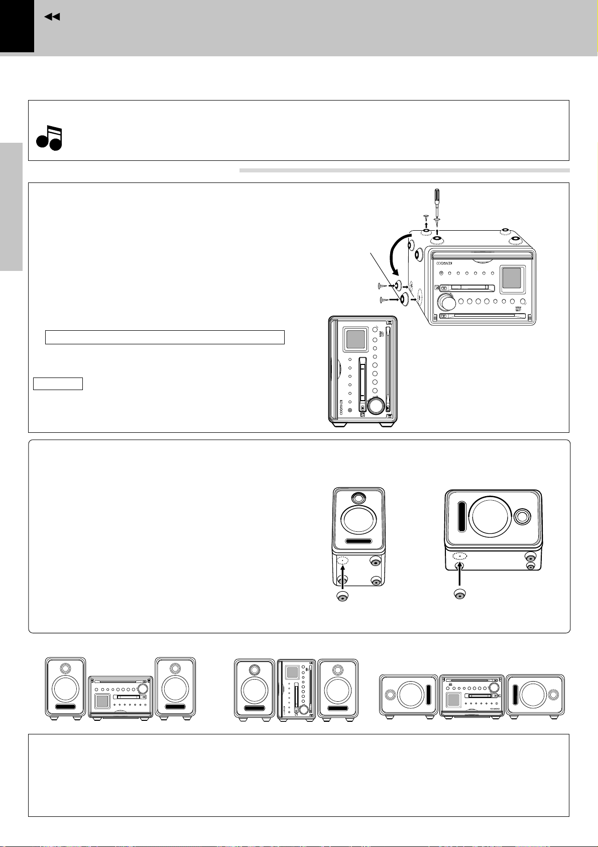
The system features a free layout with which both the main unit and speakers can be installed either on their
bottom (horizontally, or widthwise) or on their side (vertically, or lengthwise).
CAUTION
÷ When attaching replacement front feet, use only the screws which have been used with the removed feet. (Using other
Notes
Notes
screws may result in a fire or malfunction.)
÷ Eject the CD, MD and unplug the power cord before installation.
Changing the installation method
Main unit
At the factory, the feet have been attached to the
bottom panel for “horizontal” installation.
Step 1
Vertical installation
Remove the foot from the bottom panel and attach
Preparation section
them onto the side panel.
1 Remove the four feet on the front and rear part of
the bottom panel using a screwdriver.
2 Attach the feet to the specified positions on the
side panel.
Use the screws removed in 1 for attaching.
3 Place the main unit so that the LCD panel comes at
the top as shown in the figure.
CAUTION
Do not install the main unit without feet. Otherwise,
Basic section
the heat produced inside cannot be well ventilated
and a fire hazard or malfunction may result.
Speakers
The speakers are shipped without feet attached.
Attach the feet by adhesion to the specified positions according to the desired layout.
Attach the four feet with the following procedure.
Feet removed
in step 1
Step 2
Micro hi-fi component system VH-5MD
timer
rem
o
te
$
›
display
TU
/BA
N
/dem
PUSH
ER
m
enu
N
D
o
M
D
^
set
disc loading mechanism
CD
^
sound
&
S
TOP
multi control
AUX
volume/
rec
phones
Vertical installation
PUSH
p
h
A
r
o
U
e
n
c
X
e
s
multi control
volume/
&
S
T
O
P
d
s
i
o
s
s
u
p
e
m
/
n
la
t
d
e
d
e
y
n
m
u
o
disc loading mechanism
$
›
M
C
D
D
T
/
^
U
^
B
N
A
N
E
R
D
View of “vertical” installation
Horizontal installation
r
e
m
o
t
e
Micro hi-fi component system VH-5MD
timer
1 Remove dust and dirt from the positions you
want to attach the feet.
2 Peel off the double-side adhesive tape from each
of the provided speaker feet. Attach each feet to
the specified position.
Apprication section
÷ When you want to change the speaker layout, peel off and
attach the feet again using commercially-available doubleside adhesive tape.
Layout examples
CAUTION
Be sure to adhere followings. Or proper ventilation will be blocked causing damage or fire hazard.
Knowledge section
÷ Do not place any objects impairing heat radiation onto the top of unit.
÷ Leave a space around the unit (from the largest outside dimension including projection) equal or greater than,
shown below.
Top panel : 50 cm Back panel : 10 cm
Page 7
Contents
System connection
1. Connection of the System Accessories
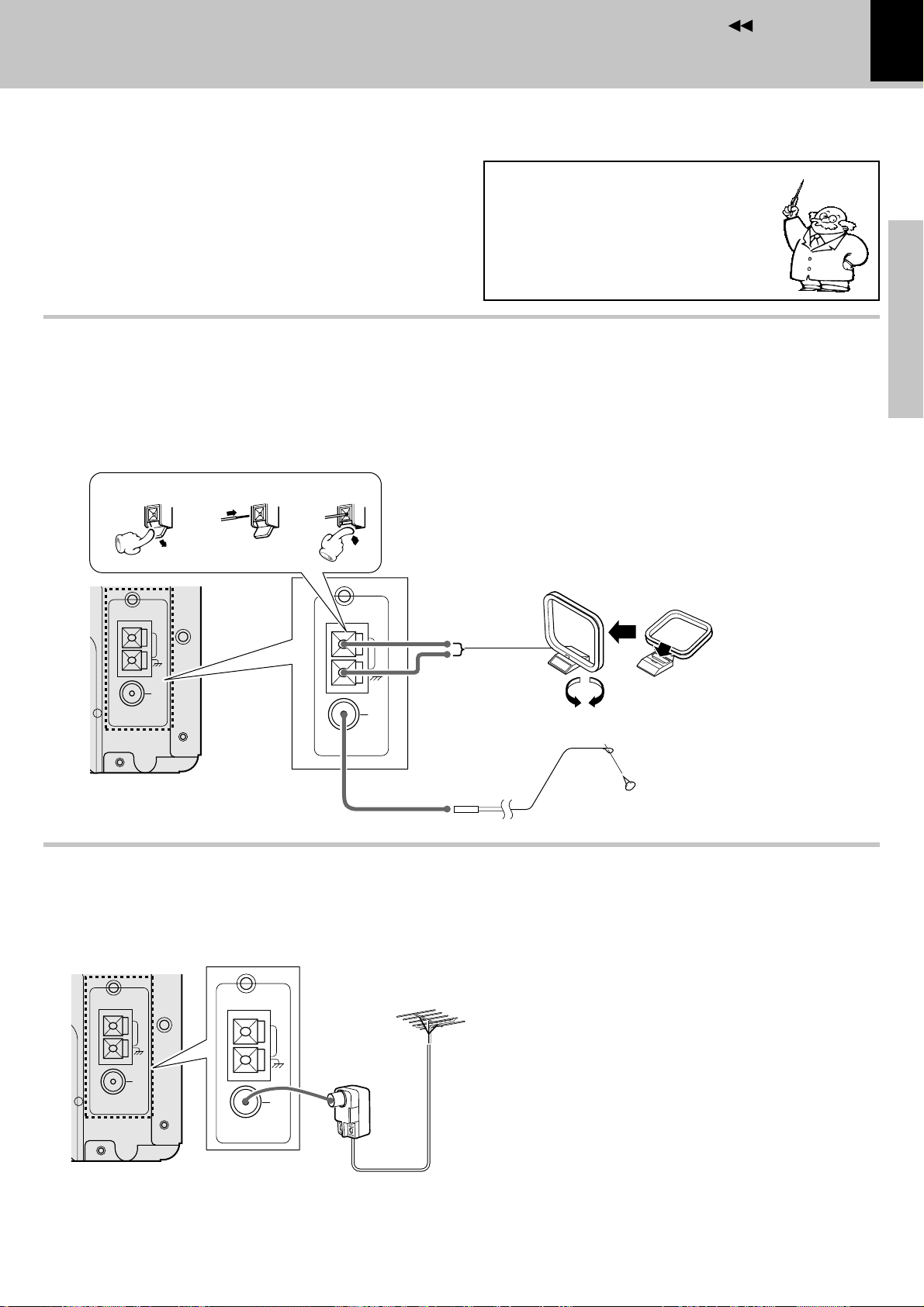
Connect the antenna as shown in the figure.
Do not plug the power cord into a wall AC outlet until
the connection has been completed.
Connection of the Accessory Antenna
AM loop antenna
The supplied antenna is for indoor use. Place it as far as
possible from the main system, TV set, speaker cords and
power cord, and set it to a direction which provides the best
reception.
1
23
Malfunction of microcomputer
If operation is not possible or erroneous display appears even though all
connections have been made properly, reset the microcomputer referring to “In case of difficulty”. l
FM indoor antenna
The accessory antenna is for temporary indoor use only. For
stable signal reception we recommend using an outdoor
antenna. Remove the indoor antenna if you connect one
outdoors.
1 Plug into the terminal.
2 Locate the position providing good re-
ception condition.
3 Fix the antenna.
System connection
7
Preparation section
Basic section
AM loop antenna
ANTENNA
GND
75Ω
AM
FM
AM
GND
FM
75Ω
ANTENNA
Assembling the antenna
FM indoor antenna
In case of bad reception
FM outdoor antenna
Lead the 75Ω coaxial cable connected to the FM outdoor antenna into the room and connect it to the FM 75Ω terminal.
Please remove the indoor antenna after an outdoor antenna has been installed.
AM
GND
FM
75Ω
ANTENNA
(Commercially available)
AM
(Commercially
available)
GND
FM
75Ω
ANTENNA
FM outdoor antenna
(Commercially available)
75Ω coaxial cable
(Commercially available)
Application section
Knowledge section
Page 8
Contents
Notes
8
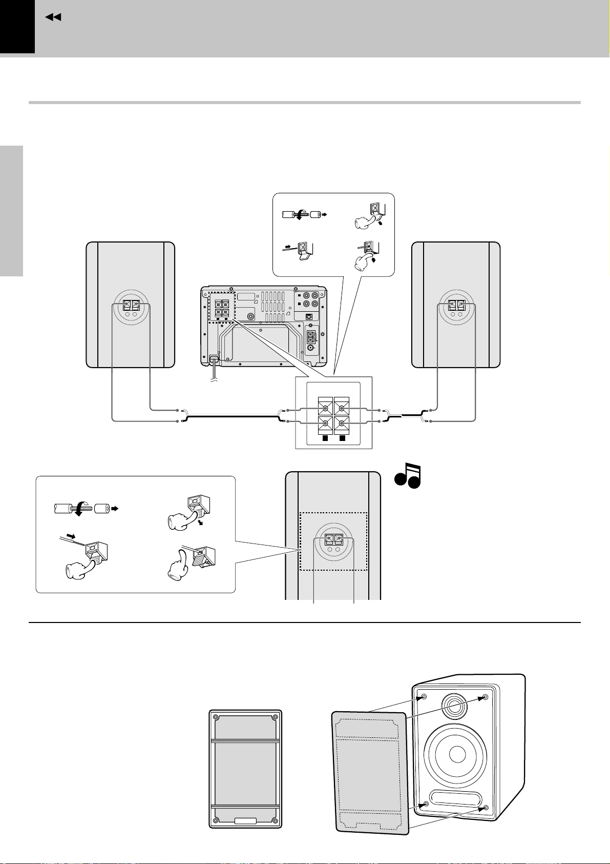
Connection of speakers
÷ Never short-circuit the + and – speaker cords.
The protection circuit will operate and no sound will be put out.
÷ The + and – polarity are inverted, the sound will be unnatural with unclear localization of musical instruments.
÷ With the speakers of this system, there is no distinction between the left and right speakers.
Main unit
System connection
Speaker (Right)
Preparation section
Basic section
Speaker rear panel
1
twist
3
Apprication section
−
+
+-+
To wall AC outlet
Speaker cord (accessories)
2
4
1
twist
3
SERIAL NO.
SUB
WOOFER
PREOUT
-
(TAPE/MD)
L
AUX
R
OUT IN
DIGITAL IN
OPTICAL
AM
GND
FM
75Ω
ANTENNA
SPEAKERS
+
-
(
)
6-16Ω
RL
2
4
+
-
Speaker cord (accessories)
Speaker (Left)
Notes
Notes
−
+
1. Be sure to insert all connection cords securely. If their connections are imperfect,
the sound may not be produced or noise
may interfere.
−
+
2. Before plugging or unplugging a connection
cord, be sure to unplug the power cord from
the wall AC outlet.
If connection cords are plugged or unplugged
with the power cord left plugged in, malfunction or damage may result.
Attaching the speaker nets
Use the following procedure when you want to attach the speaker net to each speaker.
Align the projections on the back of the speaker net
with the holes on the top edge of the speaker, and
push in gently to attach the speaker net to the speaker.
Back of the speaker net
Top
÷ The speaker net has the distinction
between the top and bottom. Check
Knowledge section
its back side to attach it in the correct
direction.
Bottom
Page 9
Contents
Notes
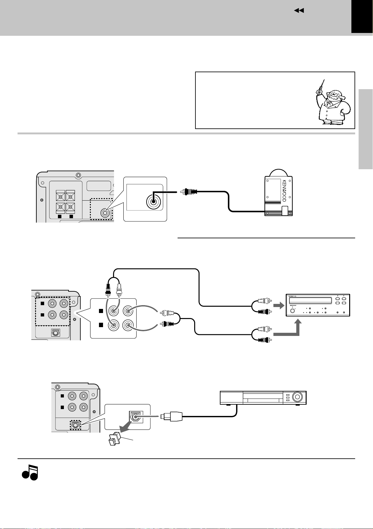
2. Connection of Other Accessories
CAUTION
When connections are to be made, make sure that
the power plug is not plugged into a wall AC outlet.
Connect the equipment as shown in the figures.
Conection of Subwoofer (optional)
Extremely low frequency sound is played back powerfully.
SERIAL NO.
+
SUB
WOOFER
PREOUT
-
SUB
WOOFER
PREOUT
+
-
SPEAKERS
(
6-16Ω
R L
)
Malfunction of microcomputer
If operation is not possible or erroneous display appears even though all
connections have been made properly, reset the microcomputer referring to “In case of difficulty”.
System connection
9
(Commercially Available Parts)
Preparation section
l
Subwoofer
Basic section
Connection of external source component
Analog signal connection
The AUX (TAPE/MD) input jacks on the rear panel can be used to connect a cassette deck, etc.
L
AUX
(TAPE/MD)
R
OUT IN
DIGITAL IN
OPTICAL
Digital signal connection
The OPTICAL digital input jack on the rear panel can be used to connect a digital component.
L
AUX
(TAPE/MD)
R
OUT IN
DIGITAL IN
OPTICAL
L
AUX
(TAPE/MD)
R
DIGITAL IN
OPTICAL
audio input
INOUT
audio output
Digital component
Optical fiber cable
Optical digital audio output
Cassette deck etc.
8
¶
027
1
3
¡
Application section
Knowledge section
Notes
Notes
* Be sure to retain the cap removed above.
1.In case an associated system component is connected, also read the instruction manual of the component.
2.Insert the optical-fiber cable straight into the connector until it clicks.
3.Be sure to attach the protection cap when the connector is not used.
4.Never bend or bundle the optical-fiber cable.
Page 10
Contents
10
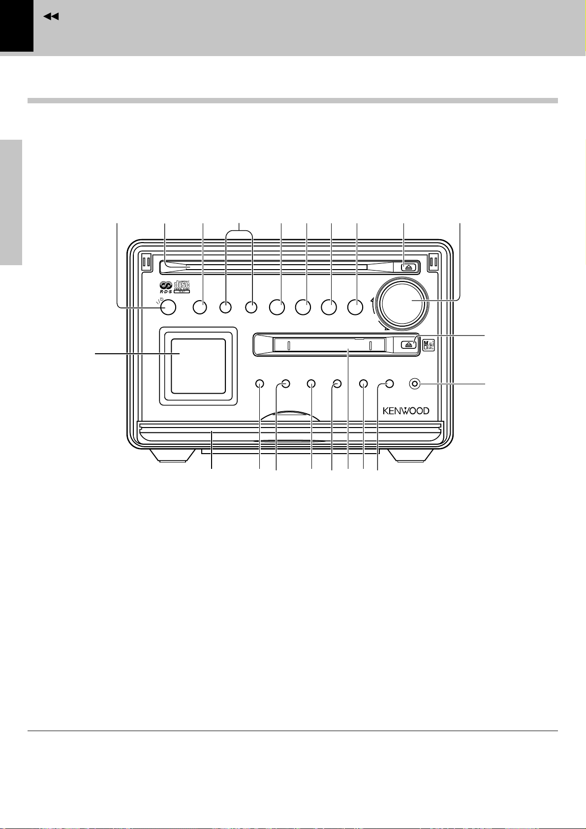
Controls and indicators
Main unit
Controls and indicators
Preparation section
!
Basic section
1 0
2
timer
micro hi-fi component system
34
remote
$
5 6 7 8 9
^
TUNER
/BAND
›
menu
display
/demo
PUSH
$ ^
MD
^
CD
disc loading mechanism
set
sound
&
&*# %@
STOP
volume/
multi-control
AUX
(
rec
phones
¡
)
Apprication section
Standby mode
Knowledge section
While the standby indicator of the unit is lit, a small amount of current is flowing into the unit’s internal circuitry to back
up the memory. This condition is referred to as the standby mode of the unit. While the unit is in the standby mode, it
can be turned ON from the remote control unit.
Page 11

Contents
1 /timer key (indicator)
Key
Press to switch the power ON and OFF (standby).
*af
Indicator
When power is ON :Light in green.
When power is OFF (standby) :Lights in red.0
During timer standby :Lights in amber.
2CD insertion slot
3Remote sensor (remote)
44 ¢ keys
During CD/MD playback:
Press to skip CD/MD tracks ¡¢
During tuner reception:
Press to select a radio station. §
5TUNER/BAND key
When power is ON:
Press to select the tuner input. §
When power is OFF (standby):
Press to turn the system power ON and start radio
reception on the tuner. *
During tuner reception:
Press to switch the radio band. §
6MD 6 key
When power is ON:
Press to select the MD input. £
When power is OFF (standby):
Press to turn the system power ON and start MD
playback. *
When MD input is selected:
Press to start playback or let it pause. £
Press when playing or recording the input source
connected to the DIGITAL INPUT jacks.¤∏
7CD 6 key
When power is ON:
Press to select the CD input. )
When power is OFF (standby):
Press to turn the system power ON and start CD
playback. *
When CD input is selected:
Press to start playback or let it pause. )
af
Controls and indicators
8 7 STOP key
When power is OFF (standby) :
Press to display the time of the day for 5 seconds.
%
During CD/MD playback : Press to stop playback.
¡¢
During MD recording : Press to stop recording.
‹
9 0 (CD eject) key
This key is pressed to remove CD. The key lights when
a CD is loaded inside. ¡
0 volume/multi-control knob
This knob is usually used to adjust the listening volume
but can also be used in setting selection, timer reservation and clock adjustment operations.
%^&*
! Character data display
@ Front door 5
# display key
Press to switch the graphics in the display. $
$ menu/demo key
Press to switch on/off the setting selection modes and
demonstration mode. 5%^
% set key
When power is ON :
Press to set or enter a menu item. %^
^ sound key
Press to adjust the tone. (
& MD insertion slot
* AUX key
Press when playing or recording the input source connected to the AUX (analog) input jacks. ¤∏
( rec key
Press to start recording. ‹
) phones jack
Plug headphones with a stereo mini-plug (optional).
(
¡ 0 (MD eject) key
This key is pressed to remove MD. The key lights
when a MD is loaded inside. ¢
11
Preparation section
Basic section
Application section
Knowledge section
Page 12
Contents
12
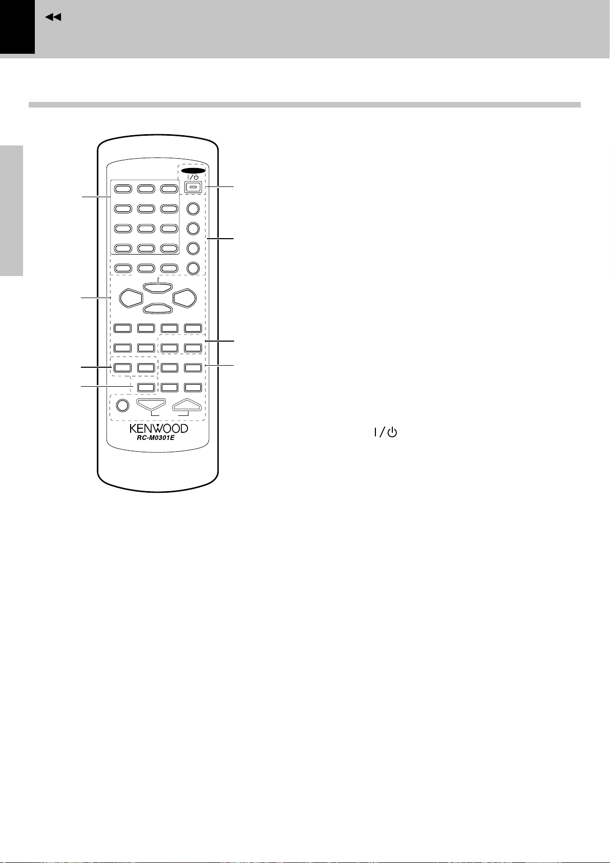
Remote control unit
1 2 ABC 3 DEF
1
Preparation section
2
3
4
Basic section
4 GHI 5JKL 6 MNO
7 PRS 8TUV 9 WXY
+100
( )
&
-
0QZ +10’,:
CLEAR
PGM
TIME
/SPACE
MD
66
TUNING P.CALL
14
AUX
REPEAT RANDOM SLEEP
MUTE
/CHARAC.
AUTO/MONO
DISPLAY
PTY
STOP
7
1
/DELETE
TUNER/BAND
MD O.T.E.
TONE
VOLUME
POWER
TITLE INPUT
TRACK EDIT
SET
ENTER
CD
¢
TITLE
SEARCH
TIMER
SOUND
5
6
7
8
Controls and indicators
4,¢ keys
During CD or MD playback:
Press to skip CD or MD tracks ¡¢
During tuner reception:
Press to select a radio station. §
1,¡ keys
During CD or MD playback:
Press to fast forward or fast reverse the disc.
¡¢
During tuner reception:
Press to select radio stations. •
AUX key
Press when playing or recording the input source
connected to the AUX (analog) input jacks.¤∏
DISPLAY key
Press to switch the graphics in the display. $
3Keys related to CD and MD
REPEAT key
Press for repeat playback of a CD or MD. ‚
RANDOM key
Press to play the tracks in a CD or MD in a random
order. q
4PTY key
Used at the time of program type detection. º
5POWER ( ) key *af
Infrared ray system
Model : RC-M0301E
1Character/numeric keys
When CD or MD input is selected:
Press to enter numbers. ¡¢
During tuner reception:
Press when recalling a preset radio station.
Apprication section
When MD title input operation
Used to enter alphanumeric and symbol characters.
2Basic operation keys
TUNER/BAND key
Press to select the tuner input. §
This key is also used to switch the broadcast bands.
MD6 (play/pause) key *£
CD6 (play/pause) key *)
STOP 7 (stop) key
When power is OFF (standby) :
Press to display the time of the day for 5 seconds.
Knowledge section
During CD or MD playback : Press to stop playback.
During MD recording : Press to stop recording.
§•
Œ
§
%
¡¢
‹
6Keys related to MD
TITLE INPUT key
This is used in MD title input operation. P
TRACK EDIT key
This is used in MD editing for reordering tracks,
deleting tracks, etc.
ipWRYIO
SET key
When CD or MD input is selected:
Press to set or enter a program. °i
ENTER key
When MD input is selected:
This is used to execute an MD editing operation or
to enter an input title. ∞ioQE
TYUIO´´
During tuner reception:
Press to enter a manual preset station. •
TIME/SPACE key
When CD or MD input is selected:
Press to switch the time information displayed
during CD or MD playback. ™¢
Press to enter a space during MD title entry.
Œ„
Press to vary the character scrolling speed. &
During tuner reception:
Press to change the radio station name display or
frequency display. ª
Page 13
Contents
PGM/CHARAC.(AUTO/MONO) key
When CD or MD input is selected:
Press when selecting program playback or an
input character group. °Œ„
During tuner reception:
Press to switch the tuning mode of the tuner.
CLEAR/DELETE key
This key is used to clear the program. During title
input, it is used to delete a character.·Œ„
7 Keys related to MD
TITLE SEARCH key
This is used in searching an MD title. ∞
MD O.T.E. key
Press during CD playback to record the currently
playing track onto MD. rt
Press during stop to record a CD from track number 1.
•
et
Controls and indicators
8 Keys related to timer and sound
TIMER key
Press to execute or cancel a timer program.
SLEEP key
Press to set the sleep timer. g
SOUND key
Press to select S.DIRECT, N.B.1, N.B.2 or TONE.
TONE key
Press to adjust the highest and lowest frequencies.
VOLUME key
Press to adjust the listening volume or tone.
Press to select the PTY SEARCH. º
MUTE key
Press to mute sound temporarily. (
a
(
(
*(
13
Preparation section
Basic section
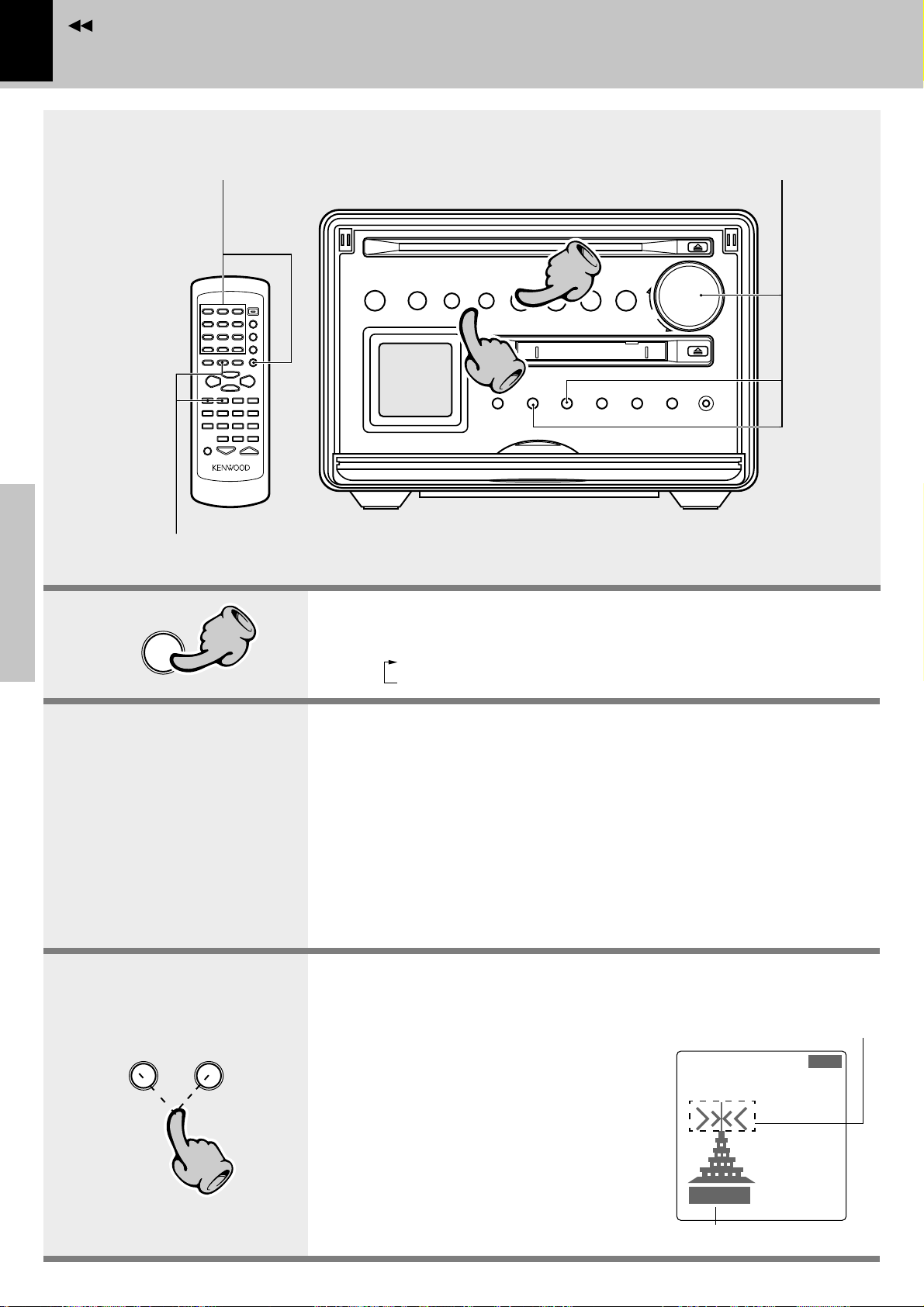
Operation of remote control unit
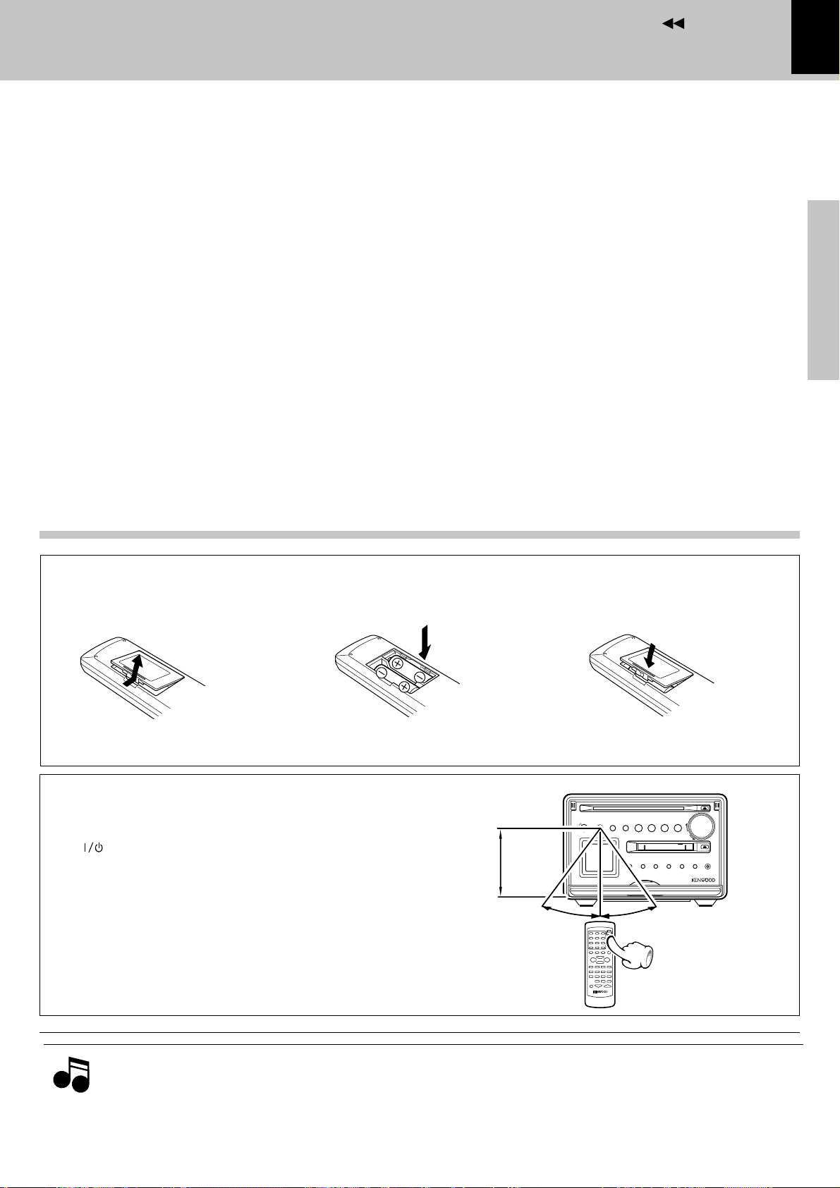
Loading batteries
1 Remove the cover. 2 Insert batteries.
÷ Insert two R6 (“AA”-size) batteries fol-
lowing the polarity indications.
Operation
Plug the power cord into a power outlet and press
the “ POWER” key on the remote control unit to
switch the power ON. Then press the key of the
function you want to control.
÷ When pressing more than one remote control keys suc-
cessively, press the keys securely by leaving an interval of
1 second or more between keys.
6m
3 Close the cover.
R
D
E
N
N
A
30˚
e
t
o
m
e
r
timer
^
U
B
^
T
/
D
D
$
C
›
M
disc loading mechanism
o
u
m
n
y
e
e
a
d
t
l
m
/
e
p
s
is
d
PUSH
30˚
Application section
P
O
T
S
&
volume/
multi control
s
d
e
X
n
c
n
e
u
U
o
r
o
A
h
s
p
Knowledge section
Notes
Notes
1. The provided batteries are intended for use in operation checking, and their service life may be short.
2. When the remote controllable distance becomes short, replace both of the batteries with new ones.
3. If direct sunlight or the light of a high- frequency fluorescent lamp (inverter type, etc.) is incident to the remote sensor,
malfunction may occur. In such a case, change the installation position to avoid malfunction.
Page 14
Contents
14
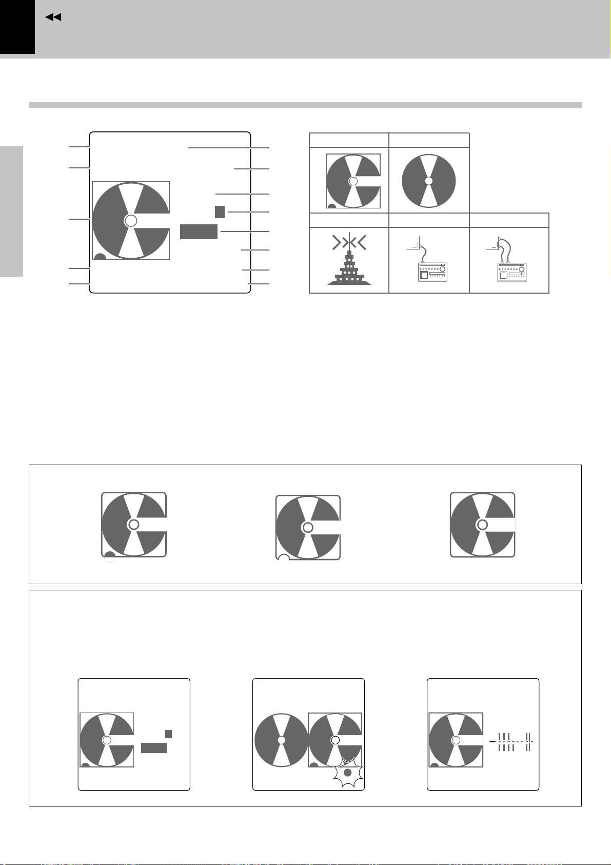
Display
1
2
3
Preparation section
4
5
1 Selector display (MD,CD,AM, FM, AUX)
2 Play(3)/Pause(8) indicator
3 Graphic display
4 Playback/tuning indicators
(TRACK, PROGRAM, RANDOM, STEREO)
5 Total tracks of entire MD
6 Track No.being played
7 Character information display
Basic section
(play time, title display, etc.)
MD0004000
‰
8:26
TONE
PROG.1
A.P.S.
12:30PM
TRACK
015
1:30
¶8
R
6
7
8
9
0
!
@
#
Controls and indicators
*1
MD CD
TUNER DIGITAL AUX
AU TO
8 Tone related indicators
(S.DIRECT, N.B.1, N.B.2, TONE)
9 TIMER-related display
(O.T.T., PROG.1, PROG.2)
0 Auto Power Save display
! Time display
@ MD rec(¶)/Pause(8) indicator
# Remaining MD recordable time display
OPT
AUX
L
R
*1 Display when an MD is loaded
Recordable MD
Apprication section
In regard to DISPLAY key
Each press of the DISPLAY key switches the graphic display. (Example of display)
Normal display
MD0004000
‰
Knowledge section
TRACK
015
8:26
TONE
PROG.1
A.P.S.
12:30PM
1:30
R
Recording-protectedMD Playback-onlyMD
Graphic display
CD 01
‰
TRACK
015
0:32
1:30
R
Level meter display
MD 005
‰
TRACK
015
26:35
TONE
L
R
12:30PM
1:30
R
Page 15
Contents
T
IME
A
DJUST
1:30
PM
TONE
TIME ADJUST
12:HOUR
‰
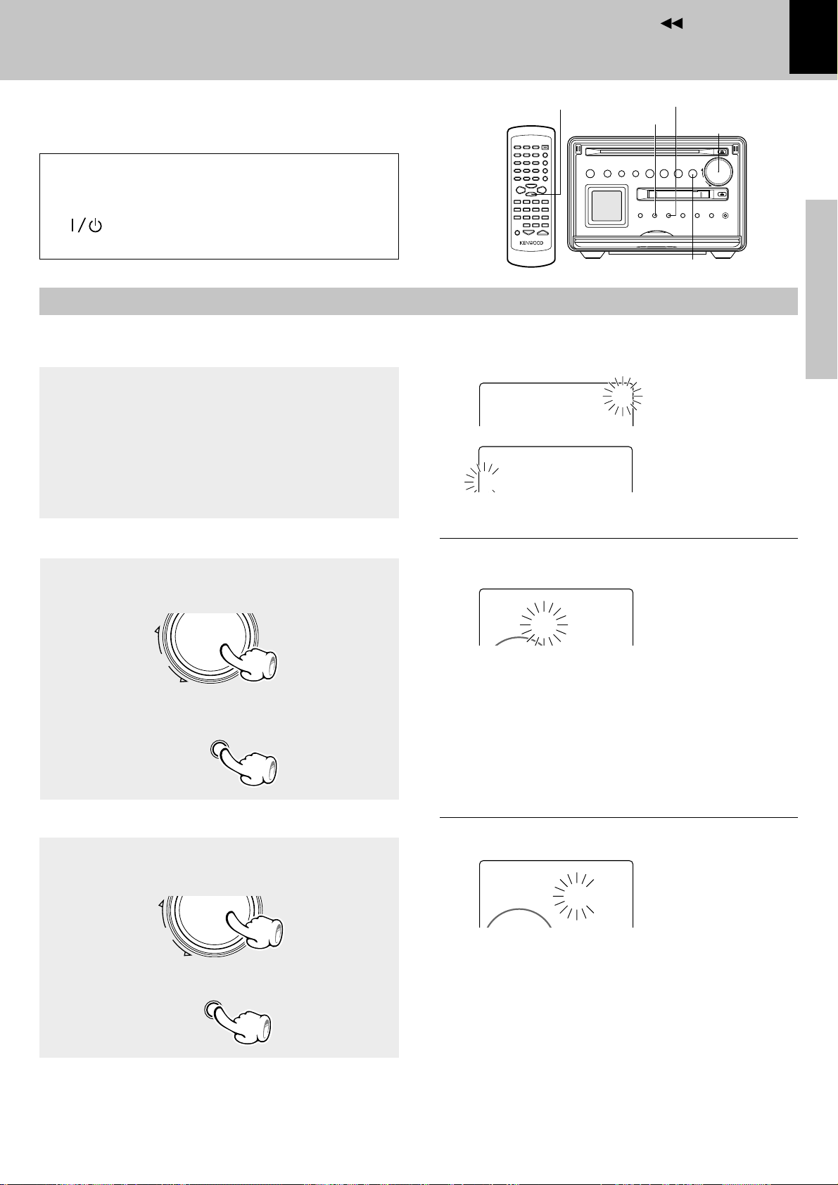
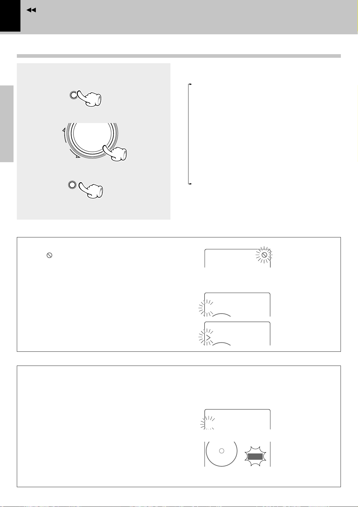
Clock adjustment
This unit incorporates a clock function. Be sure to
adjust the correct time before using the timer function.
If there is a power failure or the power cord is
unplugged then plugged in again while the power
set to off (STANDBY mode) after a timer is activated,
the /timer indicator blinks in amber.
In this case, adjust the clock again.
Switching the power ON
Activate the clock adjustment mode.
1
1 Press the menu/demo key.
2 Rotate the volume/multi-control knob to select
“TIME ADJUST ?”, then press the set key.
7 STOP
menu/demo
2 Select “TIME ADJUST ?”
T
IMEADJUST
00
?
:
3 Select the time display mode.
Menu mode
15
set
volume/
multi-control
Preparation section
7 STOP
Blinks
3 Select “12 HOUR” or “24 HOUR” by rotating the
volume/multi-control knob, then press the set
key.
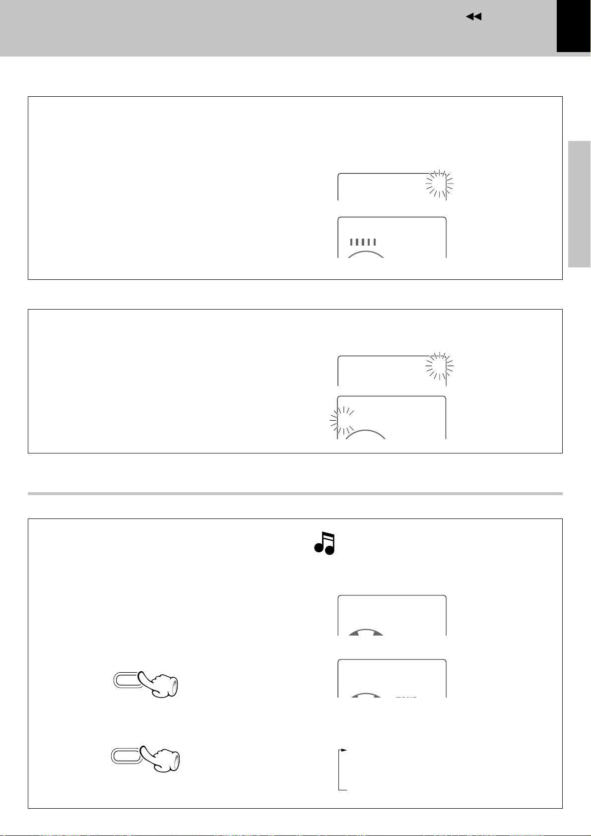
Enter the hour.
2
1 Adjust the figure of hour by rotating the volume/
multi-control knob.
To put back
the time
2 Press the set key.
Enter the minute.
3
1 Adjust the figure of minute by rotating the vol-
ume/multi-control knob.
volume/
multi-control
set
To advance
the time
Blinks
÷ The time of the day is represented in 12-hour or 24-hour
method.
1 Setting the hour
T
IME
÷ The time display starts to blink.
÷ Press the set key. The hour is entered and the minute display
starts to blink.
1 Setting the minute
Blinks
A
DJUST
1:00
PM
Example for adjusting at
0
1:30PM
Basic section
Application section
To put back
the time
2 Press the set key.
When power is OFF (standby) :
Press the 7 STOP key to display the time of the day
for 5 seconds.
volume/
multi-control
set
To advance
the time
Blinks
÷ If you pressed the set key by mistake, press the menu/
demo key and restart from the beginning.
÷ To adjust correct time, press the set key at the same moment
as a time announcement.
Knowledge section
Page 16
Contents
TIME ADJUST
12:HOUR
‰
T
IME
A
DJUST
24:H
OUR
menu
/demo
16
Menu mode
Operation in menu mode
Menu mode
1 Press the menu/demo key.
2 Select the item to be set.
Preparation section
3 Press the set key.
Set other items by repeating 2 and 3 for each.
volume/
multi-control
set
Display in menu mode
Basic section
÷ Some items cannot be selected depending on the current
mode. “
by pressing the set key.
” blinks in this case. The cause can be displayed
Each turn changes the displayed item.
“CD=MD O.T.E. ?“ .... erty
“REC TNO MARK ?“ .............................. ›
“REC INPUT ?“ .............................. ›
“AUX D. LEVEL ?“ ...................... fi∏
“AUX A. LEVEL ?“ ...................... fi∏
“MONITOR ?“ .............................. ›
“TIMER SET ?“ ......................as
“AUTOPOWERSAVE ?“ .............................. ^
“TIME ADJUST ?“ .............................. %
“AUTO MEMORY ?“ .............................. ¶
“CONTRAST ?“ .............................. &
“BACK LIGHT ?“ .............................. &
“BALANCE ?“ .............................. (
÷ The setting mode is canceled if no key or dial has been
operated for more than 20 seconds during the above.
AUXA.L
EVEL
Blinks
=
÷ The current setting is indicated by “3” and an option item is
indicated by “>”.
Apprication section
Auto Power Save (A.P.S.)
When the power has been left ON for more than
30 minutes while the unit has been doing neither recording or playback in this period, the
A.P.S. function switches the power OFF
(standby) automatically. Whether the A.P.S.
function is to be used or not can be set with the
following steps.
1 Press the menu/demo key.
2 Rotate the volume/multi-control knob to
select “AUTOPOWERSAVE ?”, then press
Knowledge section
the set key.
3 Select “ON” or “OFF” by rotating the vol-
ume/multi-control knob, then press the set
key.
“AUX A. LEVEL” is not available unless the input selector is set to “AUX”. Select the “AUX” input.
Current setting
Option item
÷ With the TUNER and AUX input, A.P.S. functions
only when the volume is set to zero.
÷ The LCD shows “A.P.S.” while this function is ac-
tive.
Blinks
A
UTOPOWERSAVE
‰
0ON
A.P.S.
12:30PM
?
Lights
Page 17
Contents
C
ONTRAST
–
00000
• • • • • • • • • •
+
CD 003
0MY Best so
‰
BACK0LIGHT
0
0HIGH
‰
LCD contrast adjustment (CONTRAST)
The contrast of the LCD display on the main unit
can be switched as desired.
÷ Adjust the contrast when the LCD display is hard to read
due to a problem in the installation position or to the
ambient temperature condition, etc.
1 Press the menu/demo key.
2 Rotate the volume/multi-control knob to select
“CONTRAST ?”, then press the set key.
3 Select the desired brightness (display density)
by rotating the volume/multi-control knob, then
press the set key.
LCD back light adjustment (BACK LIGHT)
The brightness of the back light of the LCD panel can
be switched as desired.
Menu mode
If the LCD display is hard to view (due to too high or low
contrast), press and hold the display key on the main unit
for more than 2 seconds. This resets the contrast to the
initial value.
C
ONTRAST
?
Blinks
17
Preparation section
Basic section
1 Press the menu/demo key.
2 Rotate the volume/multi-control knob to select
“BACK LIGHT ?”, then press the set key.
3 Select “LOW” or “HIGH” by rotating the vol-
ume/multi-control knob, then press the set key.
LCD scroll speed adjustment
When CD text or MD title characters scrolled on the
LCD panel are hard to read, the scrolling speed can
be switched as desired.
÷ Adjust the contrast when the LCD display is hard to read
due to a problem in the installation position or to the
ambient temperature condition, etc.
Select the “CD“ or “MD“ input. )£
1Press the TIME/SPACE key repeatedly to enter
title display mode.
TIME
/SPACE
Blinks
BACK0LIGHT00?
‰
Pressing and holding the TIME/SPACE key for more than
5 seconds resets the scroll speed to the initial value.
Title display mode
Title is scrolled.
SCROLL M IDDLE
Blinks
My Best son
Application section
Knowledge section
2 Press and hold the TIME/SPACE key for more
than 2 seconds.
3 Repeat step 2 until the desired scroll speed is
selected.
TIME
/SPACE
The scroll speed is switched every time the
operation is repeated.
“SCROLL FAST +“ High speed
(Initial value)
“SCROLL MIDDLE“ Middle speed
“SCROLL SLOW“ Slow speed
Page 18
Contents
18
Hearing sound
Hearing sound
Muting the sound temporarily
Bass and treble compensation
Preparation section
Tone adjustment
Basic section
11
Balance adjustment
Listening through headphones
33
22
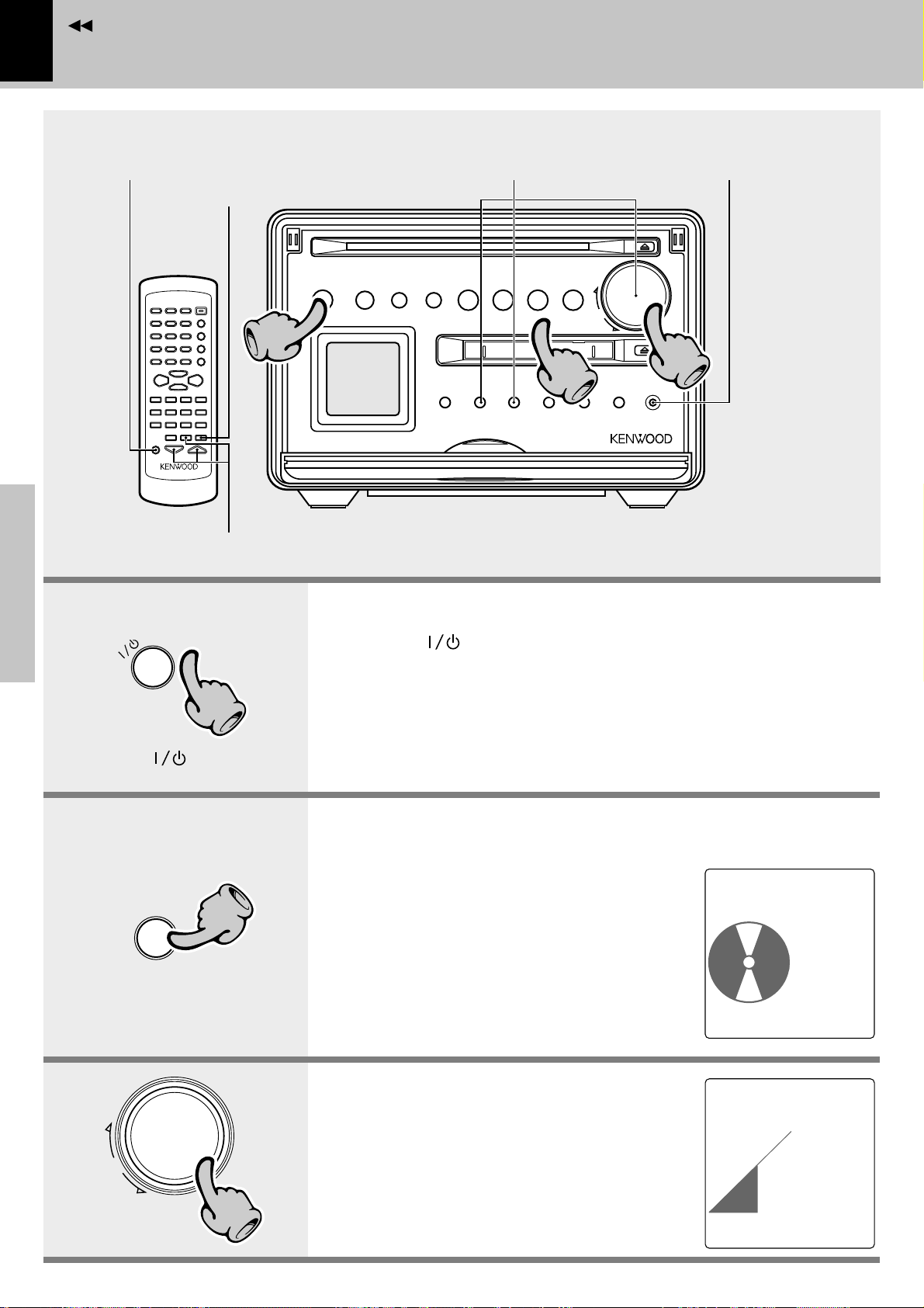
1. Switching the power ON (OFF).
When the /timer key is pressed while the power is ON, the power
will be switched OFF.
timer
Press the /timer key.
When CD has been selected.
^
Apprication section
volume/
Knowledge section
multi-control
D
C
11
22
33
÷ To protect the internal circuitry, the sound is muted for about 5 seconds after the
power is switched ON.
÷ Pressing the CD 6 , MD 6, AUX or TUNER/BAND key also turns power on and
starts playback (reception) of the corresponding input. (One-touch operation)
2. Selecting the desired output.
When CD has been
TUNER (radio broadcasting) §
CD )
MD £
AUX ∏
÷ When CD 6 or MD 6 is selected, playback
will start when a disc already has been inserted.
3. Volume adjustment.
Volume display
÷ The same function is also available using the
VOLUME keys on the remote control unit.
÷ The display shows a reference value (0~40).
selected.
CD0001
‰
TRACK
FMFMF1:30
CD0001
‰
VOL.
014
0:08
TONE
A.P.S.
12:30PM
R
1:35
TONE
A.P.S.
12:30PM
Page 19
Contents
TONE
S
OUND
0
C
ONTROL
S.DIRECT
S.DIRECT
A.P.S.
B
ALANCE
L
---+---
R
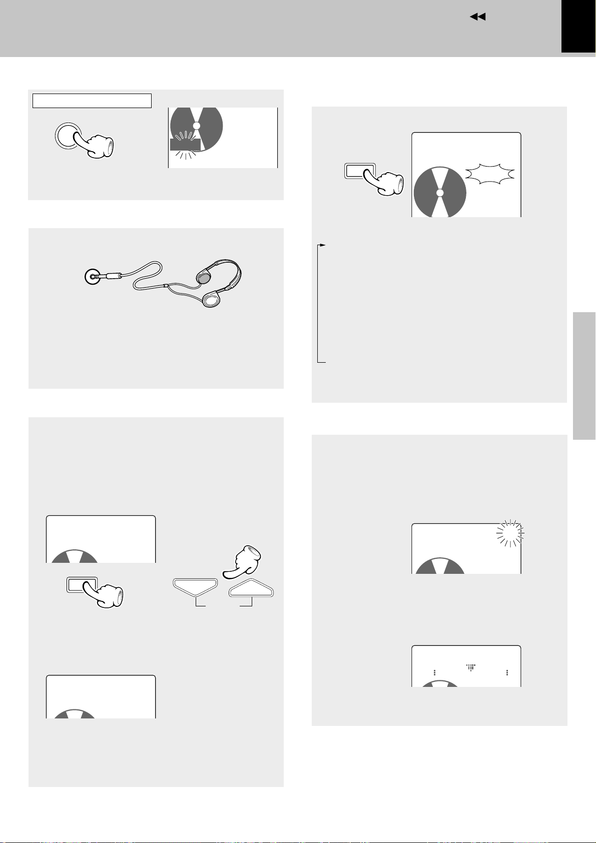
Muting the sound temporarily (MUTE)
Remote control unit only
A.P.S.
MUTE
÷ Press again to resume the original volume.
÷ This is also cancelled when the volume is adjusted.
Blinks
MUTE
TRACK
12:30PM
Listening through headphones
1 Insert the headphone plug into the phones jack.
phones
÷ Headphones with a stereo mini plug can be connected.
÷ The sounds from all speakers are cut off.
2 Adjust the volume with the volume/multi-control
knob.
Hearing sound
Bass and treble compensation
(N.B.: Natural Bass circuit)
SOUND
Each press switch the modes as follows.
“S.DIRECT” ... The source signal from a CD or MD
can be reproduced with high fidelity to the original sound by bypassing the tone control circuitry in the
main unit.
“TONE” ......... The source signal is processed by
the tone control circuitry before being output from the main unit.
“N.B.1” .......... Only the lowest frequencies are en-
hanced.
“N.B.2” .......... The lowest and highest frequen-
cies are enhanced according to the
current volume level.
19
Preparation section
Lights
Basic section
Tone adjustment (Remote control unit only)
The responses of the lowest frequencies (BASS) and
highest frequencies (TREBLE) can be adjusted as desired.
After this adjustment, the N.B. effect will be disabled.
1 Press the TONE key to select ”BASS”.
Adjust the level of lowest frequencies as desired
using the VOLUME keys.
T
ONECONTROL
0BASS 0
TONE
TONE
\
\
2 Press the TONE key again while “BASS” is dis-
played to select “TREBLE”. Adjust the level of
the highest frequencies using the VOLUME keys.
T
ONE
C
ONTROL
0TREBLE0+4
VOLUME
Balance adjustment
The balance of volumes from the left and right
speakers can be adjusted as follows.
1 Press the menu/demo key.
2 Rotate the volume/multi-control knob to select
“BALANCE ?”, then press the set key.
BALANCE
3 Adjust the left and right speaker balance by rotat-
ing the volume/multi-control knob.
4 Press the set key.
÷ This adjustment is not available when “S.DIRECT” is
selected.
00000
TONE
?
Blinks
Application section
Knowledge section
3 Press the TONE key once more.
÷ The BASS and TREBLE can be adjusted independ-
ently in the range from –4 to +4.
Page 20
Contents
20
Playback of CD
Hearing sound
Playback from
desired track
Preparation section
To fast forward
and backward
Basic section
To pause playback
To stop playback
Skipping tracks
To pause playback
11
Skipping tracks
To stop playback
22
To eject
a disc
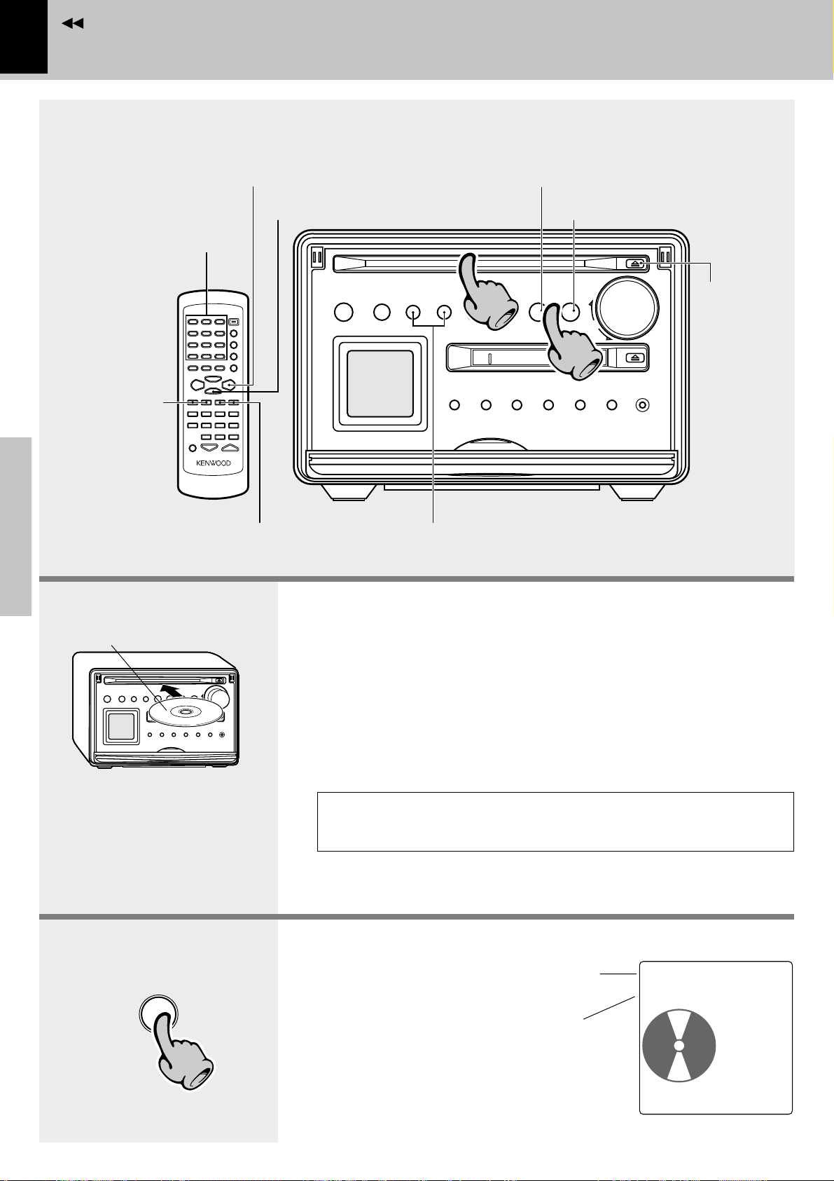
The label must be on top.
Do not touch the played surface.
Insert a disc in the insertion slot;
Apprication section
it will be pulled in automatically
into the deep of the unit.
^
CD
Knowledge section
22
1. Load/eject a disc.
Press the 0 key to eject the disc.
When taking the disc out of the unit, be sure to pull the disc straight out.
If the CD is pulled out in an oblique direction, the played surface may be
damaged.
÷ No adapter is necessary to play an 8 cm CD.
÷ Discs with certain special designs (transparent discs, etc.) may not be able to be
ejected by the first press. In such a case, try holding the 0 key depressed.
÷ If a disc cannot be inserted smoothly, try pushing it with a light force; this may
promote the automatic insertion of the disc.
The CD cannot be loaded or ejected while the unit is in standby mode.
Do not force load a CD in standby mode, otherwise malfunction will
result.
2. Start playback.
÷ After a few seconds, play starts from track No.1.
(The “CD” input is selected automatically.)
Track No. being played
(Upper line)
Elapsed track playing time
(Lower line)
CD0001
‰
TRACK
FMFMF1:30
0:08
TONE
A.P.S.
12:30PM
R
Page 21
Contents
:
To pause playback
CD
6
÷ Each press pauses and plays the CD alternately.
÷ The graphic display blinks.
To stop playback
STOP
7
Playback from desired track
Remote control unit only
Select the desired
track No.
1 2 ABC 3 DEF
4 GHI 5 JKL 6 MNO
7 PRS 8 TUV 9 WXY
+100
( )
0 QZ +10’,
-
&
Playback of CD
Hearing sound
To fast forward and backward
Remote control unit only
TUNING
1
To backward
÷ Playback starts from the position where the key is re-
leased.
1
To forward
Skipping tracks
P.CALL
¢4
To skip backward
÷ The track in the direction of the button pressed is skipped,
and the selected track will be played from the beginning.
÷ When the 4 key is pressed once during playback, the
track being played will be played from the beginning.
÷ To skip further to the previous track, press the 4 key
quickly.
÷ Tracks can be skipped by pressing the 4 or ¢ key even
in stop mode. In this case, playback starts automatically
after skipping.
To skip forward
21
Preparation section
Basic section
To eject a disc
Press the numeric keys as shown below....
To select track No. 12 .. +10, 2
To select track No. 20 .. +10, +10, 0
If the disc is stopped in the middle of loading or ejection, message “PLEASE PUSH EJECT KEY or PLAY KEY” is
displayed and the 0 key blinks. In this case, press the 0 key to eject the disc.
÷ When the 0 key is pressed, the disc is pulled inside the unit then ejected. When the CD 6 key is pressed, the disc is pulled in
and starts to be played.
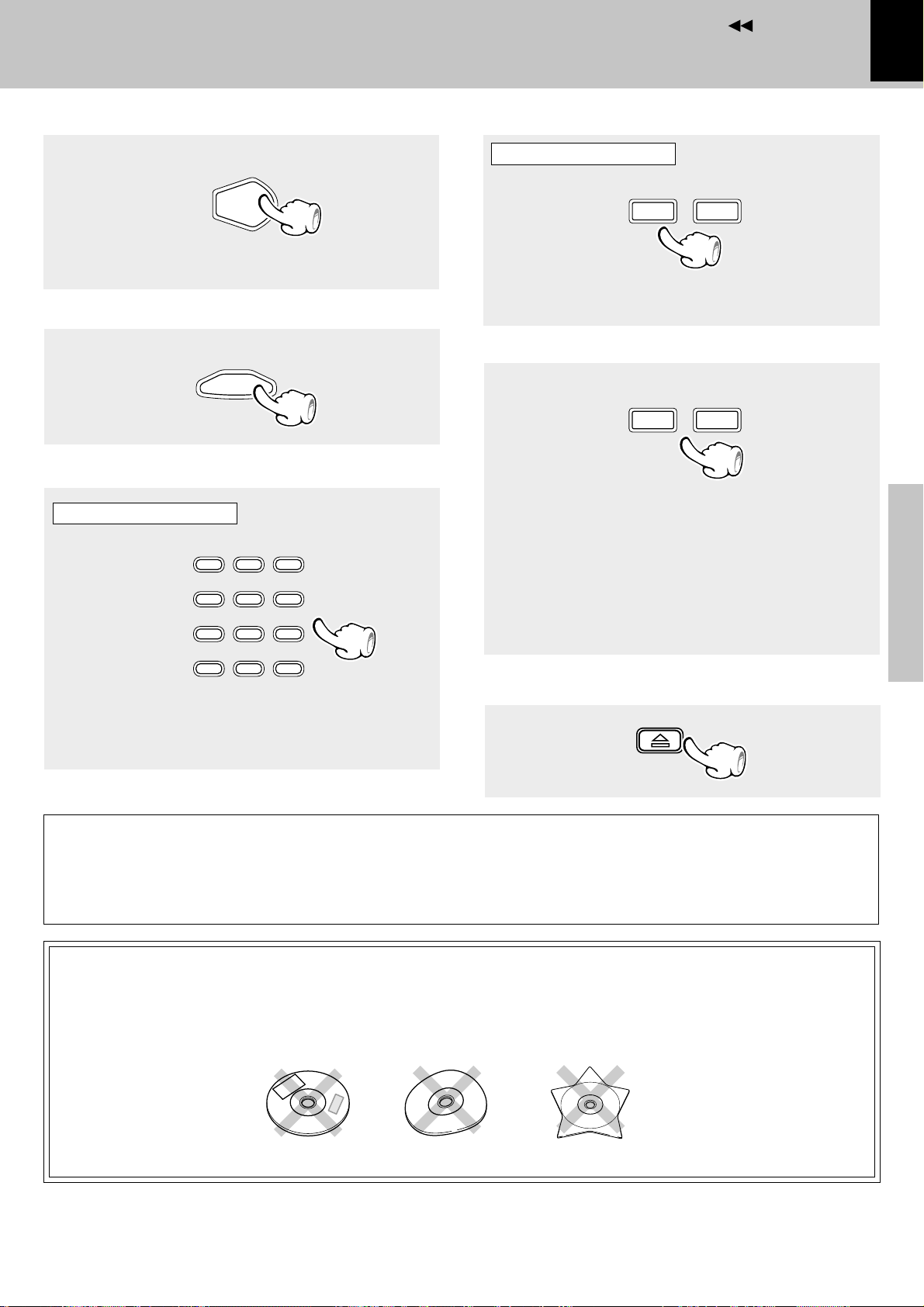
Do not attempt to insert a disc with peculiar shape (star shaped, heart
shaped, etc.), crack or important warp or a stabilizer marketed for disc
protection. Otherwise malfunction may result.
Application section
Knowledge section
Page 22
Contents
22
Time display on CD player (Remote control unit only)
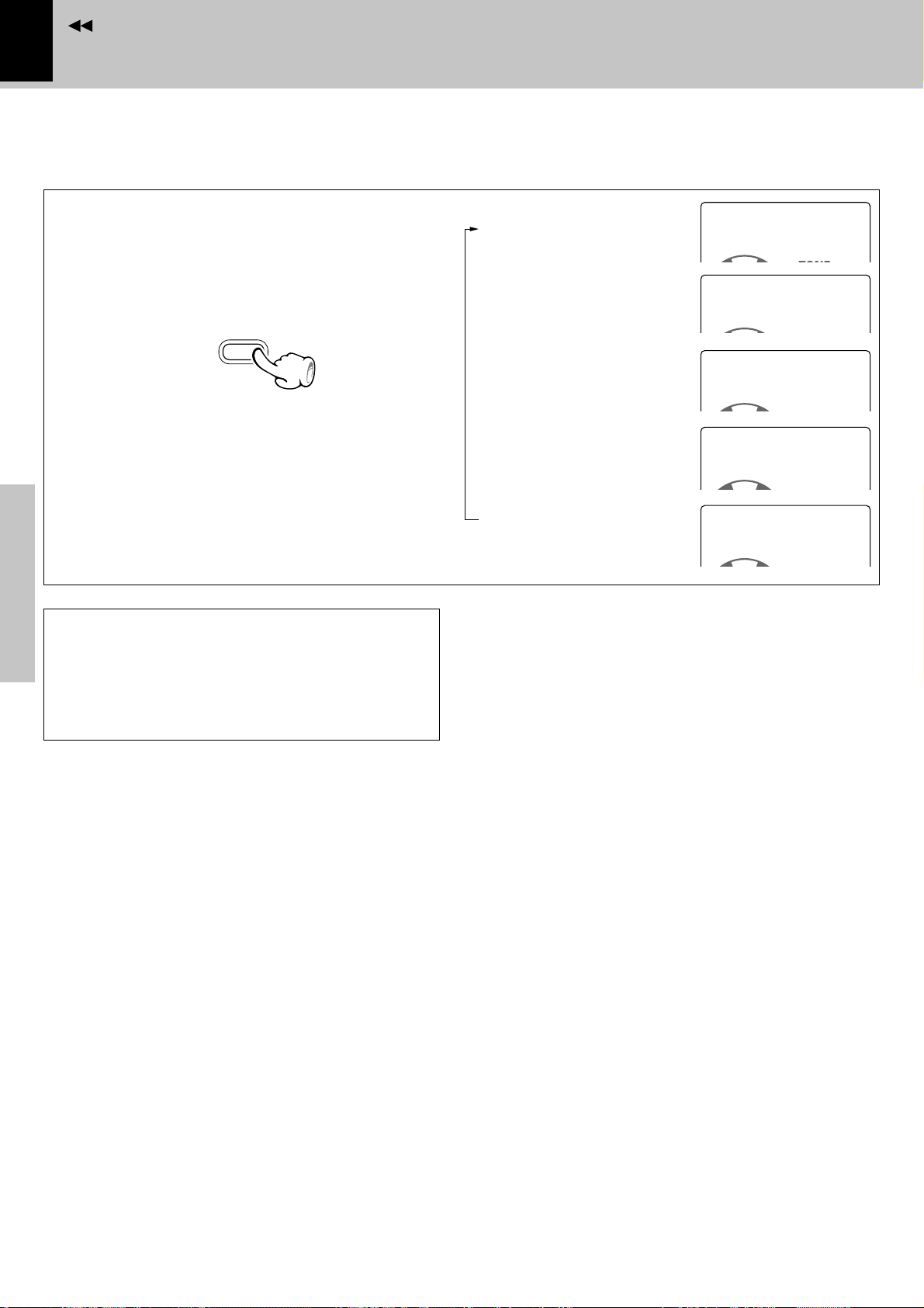
Each press of the TIME/SPACE key switches the
displayed information items one after another.
TIME
/SPACE
Preparation section
÷ When the total playing time of the tracks programmed for
program playback reaches 256 minutes or more, the
display shows “---:--T” and the time display becomes
unavailable.
÷ When a non-CD-TEXT disc is played, the CD text informa-
tion display shows “............”
Elapsed time of track
being played .........................
Remaining time of track
being played .........................
Elapsed time of
entire disc .............................
Remaining time on
entire disc .............................
CD TEXT data display
(Compatible disc only) ........
Playback of CD
Hearing sound
CD0003
‰
CD000300
‰
CD0003
‰
CD0003
‰
CD 003
‰
0MY Best so
1:28
-3:08
13:50
-47:28
T
T
CD TEXT function
Basic section
When discs conforming to CD-TEXT are played with
this unit, the text information recorded on the CD
(disc name or titles) is displayed automatically. Some
CDs conforming to CD-TEXT may not display text
information.
Apprication section
Knowledge section
Page 23
Contents
Playback of MD
To stop playback
Playback from desired track
To pause
playback
Skipping tracks
To pause playback
22
11
Hearing sound
23
To stop playback
Preparation section
Ejecting
the disc
To fast forward
and backward
In the direction of the arrow
Skipping tracks
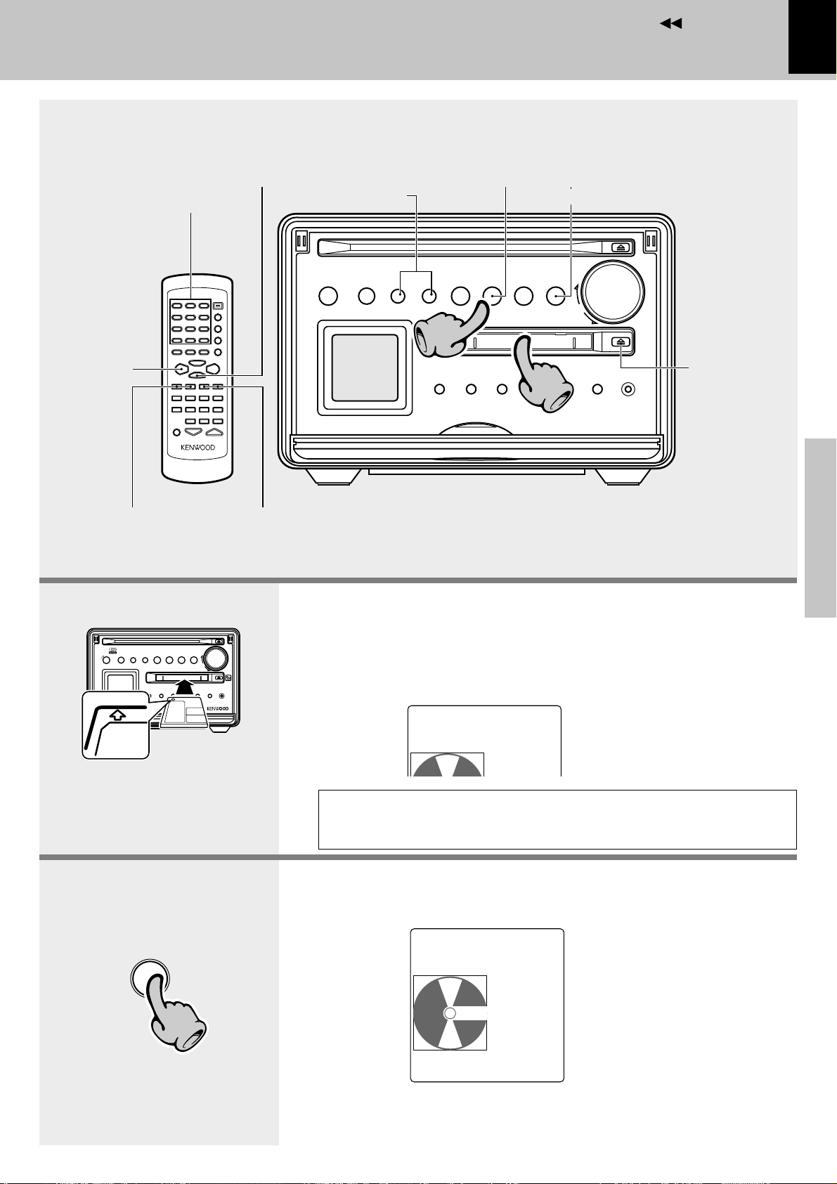
1. Load a Mini Disc
2. Start playback.
÷ Insert the minidisc correctly into the slot of this unit.
÷ The disc indicator (0) lights up when an MD is inserted.
÷ “READING” is displayed while the contents of the MD are checked.
÷ If a title has been assigned to the disc, that title will be displayed.
MD0001
0:000
TONE
The MD cannot be loaded or ejected while the unit is in standby mode.
Do not force load a MD in standby mode, otherwise malfunction will
result.
(The “MD” input is selected automatically.)
Basic section
Application section
Track No. being played
^
D
M
22
÷ After a few seconds, play starts from track No.1.
MD 001
‰
TRACK
FMFM
015
0:12
TONE
A.P.S.
12:30PM
F1:30
Elapsed time of track being played
Remaining recording time of disc
R
Continued on next page
Knowledge section
Page 24
Contents
:
24
To pause playback
MD
6
÷ Each press pauses and plays the MD alternately.
÷ The graphic display blinks.
To stop playback
STOP
7
Preparation section
Playback from desired track
Remote control unit only
1 2 ABC 3 DEF
Select the desired
track No.
Basic section
4 GHI 5 JKL 6 MNO
7 PRS 8 TUV 9 WXY
+100
( )
0 QZ +10’,
-
&
Playback of MD
Hearing sound
To fast forward and backward
Remote control unit only
TUNING
1
÷ Playback starts from the position where the key is
released.
1
To forwardTo backward
Skipping tracks
P.CALL
¢4
To skip backward
÷ The track in the direction of the button pressed is skipped,
and the selected track will be played from the beginning.
÷ When the 4 key is pressed once during playback, the
track being played will be played from the beginning.
÷ To skip further to the previous track, press the 4 key
quickly.
÷ Tracks can be skipped by pressing the 4 or ¢ key even
in stop mode. In this case, playback starts automatically
after skipping.
To skip forward
Press the numeric keys as shown below....
To select track No. 12 ... +10, 2
To select track No. 20 ... +10, +10, 0
Ejecting the disc
÷ Do not leave a Mini Disc half ejected on the insertion slot.
Time display on MD recorder (Remote control unit only)
Each press of the TIME/SPACE key switches the
displayed information items one after another.
Apprication section
TIME
/SPACE
Elapsed time of track
being played ...........................
Remaining time of track
being played ...........................
Elapsed time of
entire disc ...............................
MD0003
‰
MD000300
‰
MD0003
‰
1:28
-3:08
13:50
T
÷ When the total playing time of the tracks programmed for
program playback reaches 256 minutes or more, the
display shows “---:--T” and the time display becomes
unavailable.
Knowledge section
÷ When a track without title is played, the track number and
“............” are displayed.
Remaining time on
entire disc ...............................
MD title display ......................
MD0003
‰
-47:28
MD 003
‰
0MY Best so
T
Page 25
Contents
Playback of MD
Hearing sound
Searching a desired track by its title
(TITLE SEARCH)
When the titles of the tracks recorded on a minidisc for recording are entered in advance, search by title is
possible for the tracks to be played.
Before using the editing function, press the PGM/
CHARAC. key so that “TRACK” lights.
Select the “MD” input.
Press the TITLE SEARCH key.
1
SEARCH
TITLE
£
TITLE
‰
001 KENWO
TITLE
SEARCH
TONE
Characters flow
toward the left.
25
Preparation section
Select the desired ttitle.
2
P.CALL
¢4
To smaller
track No.
To abort operation, press the TITLE SEARCH key again
Start playback.
3
ENTER
To larger
track No.
÷ With a track to which no title has been assigned, the track
number and “• • • • • • •” are displayed.
Track played
TITLE
‰
0002 Fines
TITLE
SEARCH
÷ The track can also be selected using the numeric keys.
MD 0060
‰
Happy Hap
TONE
TONE
Characters flow
toward the left.
Characters flow
toward the left.
Basic section
Application section
TRACK
015
A.P.S.
12:30PM
1:30
R
Knowledge section
Page 26
Contents
11
26
Receiving broadcast station
One-by-one presetting
Preparation section
33
Receiving broadcast station
Presetting R.D.S.stations
(auto memory)
Tuning a non-preset
radio station
Basic section
TUNER
/BAND
Apprication section
11
1. Select the tuner input.
Each press of the TUNER/BAND key switches the band as follows.
FM
AM
2. Preset a radio station in memory .
Presetting R.D.S.stations (auto memory)
Follow the procedure in “Presetting R.D.S.stations (auto memory)” to
preset automatically the tunable radio stations in your area. ¶
÷ Once stations are stored by auto memory, the present procedure is not
required from the next time, unless you move of house or re-execute presetting
of all tunable stations.
One-by-one presetting (manual preset) •
A station can also be tuned even when it is not preset. For details, read
“Tuning a non-preset radio station (Auto tuning, Manual tuning)”•
3. Tuning (Preset Call)
$
Knowledge section
›
33
If radio stations have already been stored
with auto presetting or manual presetting,
select a station using the 4,¢ key.
Each press of the same key switches the
preset stations in sequence.
Press ¢ for the order of
1=2=3 ... 38=39=40=1...
Press 4 for the order of
40=39=38 ... 3=2=1=40...
÷ To select a preset station from the remote,
use the 4, ¢ key or numeric keys.
Tuning indicator lights up
when a station is received.
FM P08
RDS
BAYERN 3
TONE
AU TO
STEREO
Lights during stereo reception
A.P.S.
12:30PM
Page 27

Contents
Presetting R.D.S.stations (auto memory)
1 Press the TUNER/BAND key to select the TUNER
input.
TUNER
/BAND
2 Press the menu/demo key.
menu
/demo
3 Rotate the volume/multi-control knob to select
“AUTO MEMORY ?”, then press the set key.
Receiving broadcast station
Up to 40 stations can be memorized.
27
Preparation section
volume/
multi-control
\
\
set
A
UTO
M
EMORY
÷ The station name is not displayed if the tuned frequency does
not have the station name setting or when the Tuning
indicator ( ) is not lit.
÷ When auto preset completes, the first station preset by it will
be displayed.
÷ The previously preset frequencies are overwritten.
÷ For use of the RDS function, stations must be memorized by
RDS auto presetting.
÷ RDS stations are given priority during auto presetting. If there
is memory left after presetting, the receiver continues presetting regular FM stations.
÷ For memorizing of stations other than RDS stations (FM,
AM), memorize the stations according to chapter “One-by-
one presetting (manual preset)”. •
?
Blinks
Basic section
Application section
Knowledge section
Page 28

Contents
FM P--
MEMORY
28
Tuning a non-preset radio station (Auto tuning, Manual tuning)
1 Press the TUNER/BAND key to select “FM” or
“AM”.
2 Press the PGM/CHARAC. key to select auto tun-
ing or manual tuning.
Normally, use the “AUTO” (Auto tuning) mode.
Preparation section
AUTO/MONO
3 Press the 1,¡ key to receive a station.
Auto tuning mode :
Each press receives a new station.
Manual tuning mode :
Press repeatedly until the desired station is re-
Basic section
ceived.
1
To decrease
frequency
PGM
/CHARAC.
TUNING
TUNER/BAND
1
To increase
frequency
÷ Use the manual tuning mode when reception is noisy due to
weak reception. (In the manual mode, stereo broadcasts are
received in monaural.)
Each press of the key alternates these tuning
modes.
“AUTO”
AU TO
STEREO
“MANUAL”
MAN UAL
Receiving broadcast station
TONE
A.P.S.
12:30PM
TONE
A.P.S.
12:30PM
One-by-one presetting (manual preset)
1 Perform the procedure in “Tuning a non-preset
radio station” to receive the station you want to
preset.
Apprication section
2 Press the ENTER key during reception.
ENTER
3 Select the desired preset number between 1 and
40 using the numeric keys on the remote control
unit.
4 Press the ENTER key.
ENTER
Knowledge section
The preset operation is canceled when no key has been
pressed for more than 20 seconds during operation.
Blinks
÷ Repeat steps 1~4 to preset other stations.
÷ If several stations are preset under the same number,
the previous memory is replaced with the latest
memory contents.
FM P03
MEMORY
Lights
90.00MHz
Page 29

Contents
Using R.D.S.
RDS is a system that transmits useful information (in
the form of digital data) for FM broadcasts along with
the broadcast signal. Tuners and receivers designed
for RDS reception can extract the information from
the broadcast signal for use with various functions,
such as automatic display of the station name.
(Radio Data System)
This unit is equipped with the following
functions utilizing RDS data:
PS (Program Service Name) Display : (See below.)
When an RDS broadcast is received, the station name
is automatically displayed.
PTY (Program Type Identification) Search : º
The tuner automatically searches for a station which is
currently broadcasting a specified program type (genre).
Receiving broadcast station
For reception of RDS stations, the RDS auto presetting function must be used to preset the stations.
¶
FM P08
RDS
BAYERN 3
TONE
AU TO
STEREO
The “RDS” indicator lights up when
an RDS broadcast (signal) is received.
Some functions may not be provided or be given different
names depending on countries or areas.
A.P.S.
12:30PM
29
Preparation section
Basic section
To switch the display contents
Press the TIME/SPACE key.
Pressing the TIME/SPACE key changes the
display contents.
TIME
/SPACE
Display mode priority ranking
PS (Program Service Name) Display :
FM P08
RDS
BAYERN 3
When an RDS broadcast is received, the station name
is automatically displayed.
If no PS data was sent, “NO PS” is displayed.
Frequency Display :
FM P08
RDS
106.60MHz
The frequency of the current station is displayed.
Application section
Knowledge section
Page 30

Contents
30
Searching for a desired program type
By specifying the type of program (genre) you want
to listen to, the tuner automatically searches for a
station which is currently broadcasting a program of
the specified type.
Under certain receiving conditions, it may take more
than 1 minute to complete the search.
Set the reception band to FM.
Activate the PTY search mode.
1
Preparation section
Press the PTY key.
PTY
Select the program type you desire.
2
Use the program type table on the right for your
convenience.
To select using the VOLUME keys
Basic section
Previous
program type
The VOLUME keys let you select from all 29
program types in the order shown at right.
Press the key and release it when the desired
type is displayed.
VOLUME
Next
program type
Apprication section
For reception of RDS stations, the RDS auto presetting function must be used to preset the stations.
PTY S
When an RDS broadcast is received, the program type
is shown on the display. If no PTY data is available, or
if the station is not an RDS station, “NONE” is displayed.
Program type table
(fi)
DOWN
5
(%)
UP
Receiving broadcast station
(PTY search)
EARCH
POP M
Program Type Name Display
Pop Music POP M
Rock Music ROCK M
Easy Listening Music EASY M
Light Classical LIGHT M
Serious Classical CLASSICS
Other Music OTHER M
News NEWS
Current Affairs AFFAIRS
Information INFO
5
Sport SPORT
Education EDUCATE
Drama DRAMA
Culture CULTURE
Science SCIENCE
Varied VARIED
Weather WEATHER
Finance FINANCE
Children’s programs CHILDREN
Social Affairs SOCIAL
Religion RELIGION
Phone In PHONE IN
Travel TRAVEL
Leisure LEISURE
Jazz Music JAZZ
Country Music COUNTRY
National Music NATION M
Oldies Music OLDIES
Folk Music FOLK M
Documentary DOCUMENT
Using R.D.S.
¶
Knowledge section
Page 31

Contents
AU TO
FM P08
BAYERN 3
TONE
STEREO
A.P.S.
12:30PM
RDS
Start the search.
3
Press the PTY key.
PTY
To select another program type
Repeat steps 1, 2 and 3.
÷ No sound is heard while “ROCK M” is blinking.
÷ If the desired program type cannot be found, “NO PRO-
GRAM” is displayed, then after several seconds the display
returns to the original display.
÷ If the desired program type is found, that program is re-
ceived. The program type display changes temporarily to the
frequency display, and then to the station name display.
Receiving broadcast station
EXAMPLE: Searching for a Rock Music broadcast.
Display while searching
PTY SEARCH
Blinks
Using R.D.S.
ROCK M
Program type name display
÷ When the PTY is received, the PTY name blinks and the
“ROCK M” lights up.
Display when a station is received.
Station name display
31
Preparation section
Basic section
Application section
Knowledge section
Page 32

Contents
22
32
Recording on MD
Recording on MD
To pause recording
Preparation section
Basic section
To stop recording
11
To pause recording
1. Make the preparations for recording.
To stop recording
55
44
In the direction of the arrow
Apprication section
When CD has been
selected.
^
D
C
Knowledge section
22
1 Open the write protect tab of the Mini Disc to make it recordable.
2 Load the Mini Disc.
The MD cannot be loaded or ejected while the unit is in standby mode.
Do not force load a MD in standby mode, otherwise malfunction will
result.
2. Select the source to be recorded.
TUNER (Broadcasts) : Press the TUNER/BAND key
CD : Press the CD 6 key
AUX
Analog recording : Press the AUX key
AUX
Digital recording : Press the MD 6 key
÷ If a CD or MD has already been loaded, it starts to play
now. Press the 7 STOP key to stop it.
÷ When AUX (digital) is selected, the audio cannot be
monitored unless the MONITOR mode in the menu
is set to “ON”. ›
When a CD-TEXT disc is recorded, the text
data is not copied onto the MD.
CD 01
0:00
TONE
A.P.S.
12:30PM
TRACK
The selected recording
source is displayed.
Page 33

Contents
Note
rec
Recording on MD
3. Make the preparations for recording.
TUNER (Broadcasts) : Select a station
CD : Enter pause mode at the beginning of the track
to be recorded.
AUX
Analog recording : Make preparation for tuning or playback.∏
Digital recording : Set the MONITOR mode of the menu to “ON”
then make preparation for tuning or playback.
÷ The recording format can be selected according to the input source as required.
(REC INPUT) ›
÷ The input level of an external input source can be selected as required.
(AUX A. LEVEL/AUX D. LEVEL) fi
÷ When recording an MD, the track number assignment can be selected as required.
(REC TNO MARK) ›
4. Start recording.
1 Press the rec key. (the unit enters record-pause mode)
2 When the preparation is complete, press the rec key again.
33
Preparation section
›∏
Basic section
÷ When the input source is a CD, the MD recording starts at the same time as the
CD 6 key is pressed. (Synchronized recording)
3 Play (or tune) the music source to be recorded.
5. After recording , eject the MD.
÷ Be sure to eject the MD after recording. The data on the recording is written in the
MD while “WRITING” is displayed, then the disc is ejected.
While “WRITING” is displayed, do not apply shock or vibra-
Note
Note
tion to the unit because information is being written on the
Mini Disc.
Pause the recording Stop the recording
^
D
M
÷ In record-pause mode, press the same key again to resume
recording from the same position. Note that the track
number increments at this time.
÷ Recording can also be started by pressing the rec key.
÷ When recording CD playback, pressing the CD 6 key lets
both MD recording and CD playback pause temporarily. To
resume the CD playback and MD recording together, press
the CD 6 key again.
÷ If the key is pressed during recording from a CD, the CD
playback also stops.
&
Application section
P
TO
S
Knowledge section
Page 34

Contents
MONITOR
ON
‰
REC TNO MARK ?
REC TNO MARK
AUTO
‰
34
Recording on MD
Turning the monitor mode ON (External digital component) (MONITOR)
The audio being recorded from an external source component
can be listened to (monitored) through this audio system.
1 Press the menu/demo key.
2 Rotate the volume/multi-control knob to select
“MONITOR ?”, then press the set key.
3 Select “ON” by rotating the multi-control knob,
then press the set key.
÷ The audio cannot be monitored while “READING” or “WRITING” of MD is displayed.
Selecting the recording input signal (REC INPUT)
Preparation section
Select the recording input signal as required.
Blinks
MONITOR ?
Blinks
1 Press the menu/demo key.
2 Rotate the volume/multi-control knob to select
“REC INPUT ?”, then press the set key.
3 Select the desired recording input signal by rotat-
ing the volume/multi-control knob and press the
set key.
÷ When recording from a CD or MD, digital recording of certain
discs may be inhibited by the SCMS*. With such a disc,
record the ANALOG input signal. (*SCMS fl)
Recorded source Recording input signal
TUNER MONO/ANALOG
CD ANALOG/DIGITAL/MONO
AUX MONO/ANALOG
AUX(MD) Digital only
REC INPUT ?
Blinks
Basic section
Track number marking in MD recording (REC TNO MARK)
When you press the set key while “REC TNO MARK” is displayed, a menu for selecting whether the track
numbers are to be marked automatically during recording (AUTO) or marked manually by yourself during or
after recording (MANUAL). Select either option with the volume/multi-control knob and press the set key.
The initial setting is “AUTO”. The track numbers are used when playing back the recording, searching for a
track or programming tracks.
1 Press the menu/demo key.
2 Rotate the volume/multi-control knob to select “REC
TNO MARK ?”, then press the set key.
3 Select “AUTO” or “MANUAL” by rotating the vol-
ume/multi-control knob, then press the set key.
Blinks
Blinks
AUTO
Usually, use this position for recording. When CD playback is recorded, the MD track number increments as the CD track
Apprication section
changes. When an external input is recorded, the MD track also increments by “1” at the moment the input signal which has
been below a certain level for more than 2 seconds increases above the level. (When tuner reception is recorded, the track
number may sometimes fail to increment due to signal noise, etc.). When recording music containing a continuous section with
a very low level, for example when recording classic music, the track number may be incremented by “1” after such a section.
In this case, cancel the track number later. It is recommended to use the MANUAL mode when recording such a kind of music.
During digital recording of CD, the track number is incremented automatically by “1” according to the data contained in the
digital information. The no-sound blank is not detected.
When the CD track number is increased during manual search of a CD, the track number recorded on the MD may sometimes
fail to be incremented.
A no sound track may sometimes created at the moment the played CD stops.
MANUAL
With this setting, the MD track number is not incremented automatically during recording. Track
numbers can be marked either during editing (by pressing the TRACK EDIT key) or after recording
Knowledge section
(by executing the DIVIDE operation W).
This setting is convenient when recording a CD which has been recorded in live or which contains
very low-level sound such as a classical music CD.
TRACK EDIT
Press during recording.
Page 35

Contents
Recording on MD
Adjusting the recording level of digital input from the auxiliary source (AUX D. LEVEL)
The level for recording the digital input signal from an auxiliary source component such as a satellite tuner or MD recorder can be adjusted.
1 Select the “MD” input. £
2 Set the MONITOR mode to “ON”. ›
3 Press the menu/demo key
4 Rotate the volume/multi-control knob to select “AUX
D. LEVEL ?”, then press the set key.
5 Press the display key to display the level meter. $
6 Adjust the recording level (-∞ ~ +12) by rotating the
volume/multi-control knob.
7 Press the set key to set the selection.
AUX D.LEVEL
AUX D.LEVEL
-12dBd
TONE
OPT L
R
A.P.S.
12:30PM
d
Blinks
?
B
Level value
B
Adjust so that these
segments light at times.
Adjusting the recording level of analog input from the auxiliary source (AUX A. LEVEL)
35
Preparation section
The level for recording the analog input signal from an auxiliary source component such as cassette deck can be adjusted.
1 Select the recording input signal (REC INPUT) as required.
›
2 Press the menu/demo key.
3 Rotate the volume/multi-control knob to select
“MONITOR ?”, then press the set key.
4 Select “ON” by rotating the volume/multi-con-
trol knob, then press the set key.
5 Press the menu/demo key
6 Rotate the volume/multi-control knob to select
“AUX A. LEVEL ?”, then press the set key.
7 Press the display key to display the level meter.
$
8 Adjust the recording level (-4 ~ +3) by rotating the
volume/multi-control knob.
9 Press the set key to set the selection.
AUX
A
UX
L
A.
A.L
R
LEVEL
EVEL
+3
L
R
A.P.S.
12:30PM
Blinks
?
Level value
Adjust so that these
segments light at times.
Basic section
Application section
Knowledge section
Page 36

Contents
36
Recording on MD
Sampling frequency
Three types of digital signals are usually used according to the sampling frequencies. The sampling frequencies
vary depending on the types of digital equipment as shown below.
32 kHz : Standard and long-hour modes of DAT, etc.
44.1 kHz : Standard mode of DAT, CD, MD, etc.
48 kHz : Standard mode of DAT, etc.
(DAT : Digital Audio Tape deck)
In general, high-quality recording based on digital signal transmission is not possible unless the source and
recorder components use the same sampling frequency. As this unit has a built-in sampling rate converter, digital
signals with 32 kHz and 48 kHz can be recorded by conversion to the MD sampling frequency (44.1 kHz).
Preparation section
Digital recording and SCMS
Designed for copyright protection, the SCMS is a
prescription that copying of digital signals as they
are in the digital form between digital audio equipment is allowable only for one generation.
Digital recording is not available with commercially
marketed music software (CD, MD, etc.) containing
the copy prohibit code.
Basic section
Copy using
analog input
In regard to display messages
Recording is not possible when one of the following messages is displayed.
Apprication section
Recording is not possible if the following characters
are displayed.
Digital recording is not possible if the following
characters are displayed.
Copy using
digital input
Copy using
analog input
Copy using
digital input
Copy using
analog input
Copy using
digital input
Digital copy
cannot be
repeated.
Copy using
digital input
“DISC FULL” : Disc is full
\ Erase undesired tracks.
YIO
“PROTECTED” : The accidental erasure protect tab is
open.
\ Close it. k
“PLAY ONLY” : A playback-only Mini Disc is loaded.
\ Load a recordable Mini Disc.
“Please Wait” : An attempt is made to record a CD in
less than 74 minutes after high-speed
recording of the same CD was started
Knowledge section
before.
\ Start high-speed recording after
the displayed time has elapsed or
record the CD with normal-speed
recording.
“UNLOCK” : The sampling frequency is not 32
kHz, 44.1 kHz, 48kHz. fl
\ Use analog recording. ‹
: The optical fiber cable is un-
plugged or loosened. (The connector is not connected.)
\ Connect the optical fiber cable
correctly. 9
“SCMS” : Digital recording is prohibited by
SCMS. fl
\ Use analog recording. ›
“NOT AUDIO” : The input digital signal is not an
audio signal.
Page 37

Contents
;
;
;
;
;
;
Recording on MD
37
Preparation section
;;
;;
;;;
;;;
Basic section
Application section
;;
;;
Knowledge section
Page 38

Contents
:
PROGRAM
A.P.S.
12:30PM
PGM-01: 07
Funny
TONE
38
Various CD/MD playback features
Various CD/MD playback features
Listening in the desired sequence
(program playback)
Desired tracks in a disc can be programmed in the desired
order and played back. (Max. 32 tracks)
Select the “CD” or“MD” input.
Check that the unit is in the stop mode.
1
Preparation section
If it is in play mode
Press the 7 STOP key.
7
Light the “PROGRAM” indicator.
2
STOP
)£
Numeric keys
PGM/CHARAC.
CD/MD 6
CD0001
0:00 0
TONE
A.P.S.
SET
CLEAR/DELETE
7 STOP
CD/MD 6
7 STOP
set
Press the PGM/CHARAC. key.
PGM
/CHARAC.
Basic section
AUTO/MONO
Enter track Nos. in the order you want to play them.
3
1 Select a track number using numeric keys.
Press the numeric keys as shown below....
To enter track No. 12 .... +10, 2
Application section
To select track No. 20 ... +10, +10, 0
2 Press the SET key.
3 Repeat steps 1 and 2.
1 2 ABC 3 DEF
4 GHI 5 JKL 6 MNO
7 PRS 8 TUV 9 WXY
+100
( )
0 QZ +10’,
&
-
SET
Lights
2 Programming1 Track selection
Blinks
PGM-01: 07
Lights
Funny son
\
\
÷ Up to 32 tracks can be programmed. When “PGM FULL” is
displayed, no more tracks can be programmed.
÷ If you do not press the SET key before the track number
display stops blinking, the track number entry is canceled.
÷ With a CD containing CD text or MD containing title text, the
text is displayed scrolling on the LCD.
TONE
Start playback.
4
Press the 6 key.
MD
6
Knowledge section
CD
6
÷ Tracks will be played in the order they were programmed (in
order of PGM-Nos.).
÷ When the 4 or ¢ key is pressed during play, the program
will jump to the preceding or the following track respectively.
÷ When the 4 key is pressed once during playback, the play
position returns to the beginning of the current track being
played.
Page 39

Contents
:
P-04 CLEAR
Notes
To add a track to the program (Remote control unit only)
1 Select the track number to be added using the
numeric keys.
Press in stop mode
Press the numeric keys as shown below....
To enter track No. 12 ..... +10, 2
To select track No. 20 .... +10, +10, 0
2 Press the SET key.
1 2 ABC 3 DEF
4 GHI 5 JKL 6 MNO
7 PRS 8 TUV 9 WXY
+100
( )
0 QZ +10’,
-
&
SET
÷ Up to 32 tracks can be programmed. When “PGM FULL” is
displayed, no more tracks can be programmed.
÷ When a track No. is entered, the track will be added to the
end of the existing program.
Various CD/MD playback features
PGM-06: 03
Funny son
TONE
A.P.S.
12:30PM
PROGRAM
39
Preparation section
Blinks
Basic section
To delete a programmed track (Remote control unit only)
Press the CLEAR/DELETE key.
Press in stop mode
CLEAR
/DELETE
÷ Each press of the CLEAR/DELETE key clears the last track in
the program.
To quit the program mode (Remote control unit only)
Press the PGM/CHARAC. key.
Press in stop mode
PGM
/CHARAC.
AUTO/MONO
÷ This unit cannot program CD and MD tracks together.
Notes
Notes
÷ The set program mode is canceled when the power is turned off.
÷ The program mode of MD is canceled when recording is started on the MD recorder.
CD 01
0:00
TRACK
Lights
Application section
TONE
Knowledge section
A.P.S.
12:30PM
Page 40

Contents
CD 07 1
4:260
‰
:
40
Repeated playback
Desired track(s) or disc can be played repeatedly.
Select the “CD” or“MD” input.
To repeat a disc
Preparation section
1 Press the PGM/CHARAC. key so that “TRACK”
lights.
2 Press the REPEAT key repeatedly until “pALL” is
displayed.
3 Press the 6 key.
Basic section
REPEAT
)£
CD
6
Numeric keys
PGM/CHARAC.
REPEAT
2 “p ALL”
CD 01
TRACK
0:00
TONE
A.P.S.
12:30PM
Various CD/MD playback features
CD/MD 6
ALL
4,¢
4,¢
Lights
CD/MD 6
To repeat a single track
1 Press the PGM/CHARAC. key so that “TRACK”
lights.
2 Select the track number to be repeated using the
numeric keys or the 4 or ¢ key. The CD or MD
playback of the selected track will start.
1 2 ABC 3 DEF
4 GHI 5 JKL 6 MNO
7 PRS 8 TUV 9 WXY
+100
( )
0 QZ +10’,
-
&
Application section
Press the numeric keys as shown below....
To enter track No. 12 .......... +10, 2
To select track No. 20 ......... +10, +10, 0
3 During playback, press the REPEAT key repeat-
edly until “p1” is displayed.
REPEAT
P.CALL
¢4
3 “p1”
Lights
To repeat selected tracks
1 Program the desired tracks by performing the
Knowledge section
procedure in “Listening in the desired sequence
(program playback)” until step 3. °
2 Press the REPEAT key to select “pALL”.
3 Press the 6 key.
To stop repeated playback
Press the REPEAT key repeatedly until any repeatrelated indicator disappears.
÷ Normal playback will continue even after the “p” indica-
tors have turned off.
Page 41

Contents
TONE
Playing tracks in a random order
(random playback)
As the titles each time are selected randomly, the
music can be enjoyed without getting tired of it.
Select the “CD” or “MD” input.
Confirm that the “TRACK” indicator is lit.
1
Press the PGM/CHARAC. key so that “TRACK” lights.
PGM
/CHARAC.
)£
PGM/CHARAC.
RANDOM
Various CD/MD playback features
7 STOP
4,¢
4,¢
7 STOP
41
Preparation section
AUTO/MONO
Start random playback.
2
Press the RANDOM key.
RANDOM
To select another track in the middle of playing one
A.P.S.
12:30PM
RANDOM
Lights
÷ Playback stops after each track has been played once.
÷ When the REPEAT key is pressed to select “
random playback will be repeated.
pp
pALL”, the
pp
To cancel random playback
Basic section
Application section
Press the ¢ key.
P.CALL
¢4
÷ Pressing the 4 key once returns to the beginning of the
track being played.
Press the RANDOM or 7 STOP key during random
playback.
STOP
RANDOM
7
or
÷ Pressing the RANDOM key continues playback of tracks in
the order they are recorded, while pressing the 7 STOP key
stops playback.
Knowledge section
Page 42

Contents
Note
42
Convenient Recording Methods
Convenient Recording Methods
Selection of the Recording Type
This unit provides the following recording features in addition to normal recording. Select the appropriate method
according to the purpose of recording.
To record a CD simpler and faster
One-touch edit high-speed recording (O.T.E.) (HIGH SPEED) (Main unit only)
All-track high-speed recording
(HIGH SPEED)
Preparation section
Single-track high-speed recording
(HIGH SPEED)
\
\
Records a CD onto an MD in a short period.
All tracks in a CD can be recorded onto an MD in half
the normal playback period. e
Records a CD onto an MD in a short period.
Records only one CD track being played onto an MD
in half the normal playback period.
(This is convenient for recording of desired tracks
from a disc being heard for the first time.) r
To record CD with a simplified method
One-touch edit normal-speed recording (O.T.E.) (NORMAL SPEED)
Basic section
All-track recording
(NORMAL SPEED)
Single-track recording
(NORMAL SPEED)
To record desired CD tracks by reordering them
Application section
\
\
Records all tracks in a CD onto an MD. t
Records only one CD track being played onto an MD.
(This is convenient for recording of desired tracks
from a disc being heard for the first time.) t
Program recording (PGM mode + O.T.E.)
Recording of programmed tracks in the programmed
Program recording
\
order.
(Convenient for recording only the desired CD tracks
in the desired order.) y
After recording an MD, be sure to eject the disc by pressing the 0 key. The information on the recording is written
Note
Note
on the disc before it is ejected.
Knowledge section
Page 43

Contents
PleaseAIT
W
ait
74
min.
High-speed recording of all tracks in a CD
One-touch edit high-speed all-track recording (O.T.E.) (HIGH SPEED)
Records a CD onto an MD in a short period. (Main unit only)
Be sure to put the MD recorder in stop mode
Make the preparations for recording.
1
1 Insert a recordable disc into the MD recorder.
2 Insert disc in the CD player.
Check the current play mode of the CD player.
2
If it is in play mode, stop it.
P
STO
&
Convenient Recording Methods
43
Preparation section
Start recording.
3
1 Press the menu/demo key.
2 Rotate the volume/multi-control knob to select
“CD=MD O.T.E. ?”, then press the set key.
3 Select “HIGH SPEED” by rotating the volume/
multi-control knob, then press the set key to start
high-speed recording.
set
volume/
multi-control
After recording , eject the MD.
4
\
\
Turning the knob switches the display contents.
1 NORMAL SPEED (normal-speed recording)
2 HIGH SPEED (high-speed recording)
÷ During high-speed recording, the CD playback audio is played
at a high speed and low volume.
÷ If you are operating the remote, press the MD O.T.E. key.
(Only “NORMAL SPEED” recording is available from the
remote control unit.)
÷ High-speed recording starts with the first track in the CD and
continues until the last track.
÷ When either high-speed CD playback or MD high-speed
recording stops, the other operation also stops.
÷ The digital input is recorded automatically.
One high-speed recording starts, it is not permitted
to record the same disc with high-speed recording
for 74 minutes after the start of recording. If you
want to record the same disc immediately, use
normal-speed recording.
Basic section
Application section
To interrupt a recording
(Recording and playback will be stopped.)
Note
Note
While “WRITING” is displayed, do not apply
shock or vibration to the unit because information is being written on the Mini Disc.
&
STO
P
÷ When “HIGH SPEED” is selected in step 3, “¶ 8”
is displayed for a few seconds until actual recording starts. If the high-speed recording is canceled
by pressing the 7 STOP key in this period, highspeed recording of the same disc can be started
without waiting for more 74 minutes.
Knowledge section
Page 44

Contents
PleaseAIT
W
ait
74
min.
44
High-speed recording of a single track in a CD
One-touch edit high-speed a single-track recording (O.T.E.) (HIGH SPEED)
Records a CD onto an MD in a short period. (Main unit only)
Be sure to put the MD recorder in stop mode
Make the preparations for recording.
1
1 Insert a recordable disc into the MD recorder.
2 Insert disc in the CD player.
Preparation section
Check the current play mode of the CD player.
2
^
Select the desired CD
track and play it.
D
C
Convenient Recording Methods
Start recording.
3
1 Press the menu/demo key.
2 Rotate the volume/multi-control knob to select
Basic section
“CD=MD O.T.E. ?”, then press the set key.
3 Select “HIGH SPEED” by rotating the volume/
multi-control knob, then press the set key to start
high-speed recording.
set
\
volume/
multi-control
After recording , eject the MD.
4
Application section
\
To interrupt a recording
P
TO
S
&
Turning the knob switches the display contents.
1 NORMAL SPEED (normal-speed recording)
2 HIGH SPEED (high-speed recording)
÷ During high-speed recording, the CD playback audio is played
at a high speed and low volume.
÷ If you are operating the remote, press the MD O.T.E. key.
(Only “NORMAL SPEED” recording is available from the
remote control unit.)
÷ Even when the recording is started in the middle of the track,
playback restarts and recording start from the beginning of
the track.
÷ After the track has been recorded, the MD recorder stops and
the CD player enters pause mode.
÷ When either high-speed CD playback or MD high-speed
recording stops, the other operation also stops.
÷ The digital input is recorded automatically.
One high-speed recording starts, it is not permitted
to record the same disc with high-speed recording
for 74 minutes after the start of recording. If you
want to record the same disc immediately, use
normal-speed recording.
(Recording and playback will be stopped.)
Knowledge section
Note
Note
While “WRITING” is displayed, do not apply
shock or vibration to the unit because information is being written on the Mini Disc.
÷ When “HIGH SPEED” is selected in step 3, “¶ 8”
is displayed for a few seconds until actual recording starts. If the high-speed recording is canceled
by pressing the 7 STOP key in this period, highspeed recording of the same disc can be started
without waiting for more 74 minutes.
Page 45

Contents
One-touch recording
One-touch edit normal-speed recording (O.T.E.) (NORMAL SPEED)
Records all tracks in a CD with a simple operation. (All-track recording)
Records a single CD track being played from the beginning. (Single-track recording)
Be sure to put the MD recorder in stop mode
Make the preparations for recording.
1
1 Insert a recordable disc into the MD recorder.
2 Insert disc in the CD player.
Check the current play mode of the unit.
2
All track recording Single-track recording
Convenient Recording Methods
45
Preparation section
If it is in play mode, stop it.
STOP
7
Start recording.
3
MD O.T.E.
After recording , eject the MD.
4
Select the desired CD track and play it.
÷ Even when the recording is started in the middle of the track,
playback restarts and recording start from the beginning of
the track.
÷ After the track has been recorded, the MD recorder stops and
the CD player enters pause mode.
÷ When either CD playback or MD recording stops, the other
operation also stops.
÷ The digital input is recorded automatically.
÷ When you are operating the main unit, select “CD
O.T.E.” in the menu mode, then select ”NORMAL SPEED”
and press the set key to start recording.
CD
6
==
=MD
==
Basic section
Application section
To interrupt a recording
STOP
7
(Recording and playback will be stopped.)
Note
Note
Knowledge section
While “WRITING” is displayed, do not apply
shock or vibration to the unit because information is being written on the Mini Disc.
Page 46

Contents
46
Program recording
Desired CD tracks can be programmed in the desired sequence and recorded onto an MD.
Be sure to put the MD recorder in stop mode
Make the preparations for recording.
1
1 Insert a recordable disc into the MD recorder.
2 Insert disc in the CD player.
Preparation section
Check the current play mode of the CD player.
2
If it is in play mode, stop it.
STOP
7
(PGM mode+O.T.E.)
Convenient Recording Methods
Program the desired sequence of CD tracks.
3
Perform steps 2 and 3 of the procedure in ”Listen-
Basic section
ing in the desired sequence (program playback)”.
Start recording.
4
MD O.T.E.
After recording , eject the MD.
5
Application section
°
÷ Recording begins from the first track in the program and
completes when the entire program has been recorded.
÷ Recording stops automatically when the program playback of
the CD completes.
To interrupt a recording
STOP
7
(Recording and playback will be stopped.)
Knowledge section
Note
Note
While “WRITING” is displayed, do not apply
shock or vibration to the unit because information is being written on the Mini Disc.
Page 47

Contents
MD Edit Functions
MD Edit Functions
Selecting the editing function type
After recording of a commercially-available recordable Mini Disc, the recording can be edited in various
ways. Note that it is impossible to edit a playbackonly Mini Disc.
The MD recorder acts based on the data loaded from
the disc into the memory. As this data is written in
the disc at the moment it is ejected, be sure to eject
the disc every time after the title input or editing
operation.
Reordering tracks by moving them Dividing a track, combining two tracks
Reordering several tracks at a time (QUICK MOVE)
i
Moving the order of the track being played in a disc
(MOVE) p
Function Limitations because of the MD Standard
Some of the functions are limited because of the MD
standard. Please check “Symptoms related to MD standard” before assuming a malfunction. ;
Before using the editing function, press the PGM/
CHARAC. key so that “TRACK” lights.
Dividing a track during playback
(DIVIDE) W
47
Preparation section
Erasing track(s)
Erasing several tracks at a time
(QUICK ERASE) Y
CBA ED F
DCBA
DABC
E FCA
ALL ERASE O
Basic section
Combining tracks during playback
(COMBINE) R
Erasing a single track during playback
(ERASE) I
DCBA
Application section
CBA
DCBA
Assigning a Title to a Disc or a Track
P
Copying a Disc or Track Title in a Title Memo
(TITLE COPY)
ˇ
Entering characters in title memo
(TITLE MEMO)
¨
To delete the edited contents (EDIT CANCEL)
ˆ
Title input is possible simply by selecting one character after another from the characters shown on
the display. As the entered title is compatible between models, it will be displayed also when the
disc is set into a different MD recorder (player).
(The title compatibility is limited partly according
to the character types which can be displayed, the
number of characters, etc.)
Knowledge section
Page 48

Contents
48
Reordering several tracks at a time (QUICK MOVE)
Use the following procedure to reorder several tracks
in a disc simultaneously by selecting them.
Before using the editing function, press the PGM/
CHARAC. key so that “TRACK” lights.
Please execute operation in stopped condition.
Select “Q.MOVE ?”.
1
Preparation section
1 Press the TRACK EDIT key .
TRACK EDIT
Each press of the 4 or ¢ keys switches the operation.
1 Q.MOVE ?
2 Q.ERASE ?
3 CANCEL ?
MD Edit Functions
2 Select “Q.MOVE ?”.
Basic section
3 Set it.
Select track numbers in the new order you want.
2
1 Select a track number.
To decrease
Application section
track No.
2 Set it.
P.CALL
SET
P.CALL
÷ Editing is aborted if no operation has been performed for 8
seconds.
¢4
EDIT
x
Q.MOVE ?
Blinks
Q.MOVE
00
1
TITLE
Blinks
Number of selected tracks
¢4
To increase
track No.
Q.MOVEoo 3
004
TITLE
3 Repeat steps 1 and 2 above.
4 Complete the selection of track numbers to
be reordered.
Knowledge section
SET
ENTER
Track No. to be moved
÷ Up to 32 tracks can be selected.
÷ Pressing the 1 or ¡ key allows to check the current order
of tracks.
÷ Press the CLEAR/DELETE key to clear the last selected track
number.
Page 49

Contents
Execute the track reordering operation.
3
1 Select the move destination.
2 Set it
P.CALL
¢4
SET
MD Edit Functions
÷ The title is scrolled if present.
Example for moving between tracks No. 5 and No. 6
Q.MOVEo
–
4
005/__/006
49
Preparation section
Basic section
3 Reorder tracks.
ENTER
Eject the Mini Disc.
4
Even after completing MD editing, it is still possible
to cancel the settings in the current editing session
and restore the disc to the condition it was loaded
last time.
Note that this is possible provided that the MD is not
ejected yet. ˆ
Q.MOVE
oo
ok?
005/–4
Display after execution
“EDIT NOW” : Editing
“COMPLETE” : When editing is completed suc-
cessfully
“CAN'T EDIT” : When editing is impossible
TRACK
WRITING
Information is
being written.
While “WRITING” is displayed, do not impact
or move the unit because information about
Note
Note
recording and editing is being written to the
Mini Disc.
A.P.S.
12:30PM
MD MD
EJECT
TONE
Mini Disc has been
ejected.
NO DISC
TONE
Application section
Knowledge section
Image of Quick Move operation
1
2 3 456 7
Track No.
1243236
Example for moving the tracks selected for reordering to the position
between tracks No. 4 and No. 5 (step 3)
25 26 27 28 2923 24
1
3
Arrangement in the desired sequence (step 2)
25
57
24
24 26 27 28 29
Page 50

Contents
50
MD Edit Functions
Moving the order of the track being played in a disc (MOVE)
This procedure shows you how to play and move a
track to the track number you desire. The surrounding tracks are renumbered automatically.
Repeating this procedure lets you arrange the tracks
in the order you desire.
Be sure to put the MD recorder in stop or pause mode.
Select “MOVE ?”.
1
Preparation section
1 Press the TRACK EDIT key.
TRACK EDIT
Before using the editing function, press the PGM/
CHARAC. key so that “TRACK” lights.
÷ If the operation is started during playback, it pauses automati-
cally.
2 Select “MOVE ?”.
Basic section
3 Set it.
Select the moving destination track.
2
1 Select the track number.
To decrease
track No.
Application section
2 Set it.
P.CALL
SET
P.CALL
SET
Each press of the 4 or ¢ keys switches the operation.
¢4
1 DIVIDE ?
2 COMBINE ?
3 ERASE ?
4 MOVE ?
÷ Editing is aborted if no operation has been performed for 8
seconds.
EDIT
x
MOVE ?
÷ The title is scrolled if present.
Example for moving between tracks No. 6 and No. 7
¢4
To increase
track No.
MOVEoo
006/__/007
Track to be moved
–
003
Destination track
No.
Knowledge section
MOVEoooo
006/–003
ok?
Page 51

Contents
Move the track.
3
ENTER
MD Edit Functions
Display after execution
“EDIT NOW” : Editing
“COMPLETE” : When editing is completed suc-
cessfully
“CAN'T EDIT” : When editing is impossible
51
Preparation section
Eject the Mini Disc.
4
Even after completing MD editing, it is still possible
to cancel the settings in the current editing session
and restore the disc to the condition it was loaded
last time.
Note that this is possible provided that the MD is not
ejected yet. ˆ
Image of track reordering by Move
1 72 3 4 5
3 4 566
21
TRACK
12:30PM
WRITING
Information is
being written.
A.P.S.
MD MD
EJECT
TONE
Mini Disc has been
ejected.
While “WRITING” is displayed, do not impact
or move the unit because information about
Note
Note
recording and editing is being written to the
Mini Disc.
22
Select the track to be moved.
Select the move destination.
7
ENDTOP
22
NO DISC
TONE
Basic section
Application section
1
3 4 5 6
2
21
22
The track has been moved.
(The track numbers are readjusted.)
Knowledge section
Page 52

Contents
52
MD Edit Functions
Dividing a track during playback (DIVIDE)
Use the following procedure to divide a track into two by inserting a track number in its middle. For example, by
inserting an additional track number before the passage you are specially fond of, it is easy to skip to there when
you play the disc later. Note that the track numbers of the tracks located after the divided track are automatically
incremented.
The preview function can be used for fine adjustment
while repeatedly listening to the track division point.
Be sure to put the MD recorder in stop or pause mode.
Play the track to be divided.
1
Preparation section
Press the TRACK EDIT key at the desired position.
2
1 Press the TRACK EDIT key
TRACK EDIT
2 Select “DIVIDE ?”
P.CALL
¢4
Before using the editing function, press the PGM/
CHARAC. key so that “TRACK” lights.
÷ When dividing a track, set the dividing point at more than
about 2 seconds after the beginning of the track.
Track division is sometimes impossible if one of the divided
section becomes shorted than about 2 seconds.
÷ If the operation is started during playback, it pauses automati-
cally.
÷ Editing is aborted if no operation has been performed for 8
seconds.
Basic section
3 Set it
If no preview is to be performed, press the
ENTER key once and then go to step 4.
When preview is to be performed.
3
1 Preview execution
Application section
2 Perform fine adjustment of the division point.
SET
SET
P.CALL
EDIT
0DIVIDE ?
DIVIDEo+00
001<>002O?
Track No.
in pause
New track No. created after division
DIVIDEo00
PREVIEWo0s
÷ Repeated playback from the division point will be performed
for about 3 sec.
¢4
DIVIDEo+04
PREVIEWo0s
3 Decide the division point.
Knowledge section
SET
÷ The dividing point can be fine-adjusted in 60 ms (6/100 sec.)
steps, between -31 and +31 assuming that the point where
the TRACK EDIT key was pressed is 0 (i.e. in the range
covering about 4 seconds).
DIVIDE
oo
ok?
001<>002
Page 53

Contents
Execute the track divide operation.
4
ENTER
MD Edit Functions
Display after execution
“EDIT NOW” : Editing
“COMPLETE” : When editing is completed suc-
cessfully
“CAN'T EDIT” : When editing is impossible
÷ There is no blank space left between the two tracks.
÷ Track division may sometimes be impossible due to the
limitations of the MD standard.
÷ The MD recorder enters pause mode at the beginning of the
track newly created by division.
53
Preparation section
Basic section
Up to 255 track numbers can be inserted
additionally by repeating 1 to 4 for each of
them.
Eject the Mini Disc.
5
Even after completing MD editing, it is still possible
to cancel the settings in the current editing session
and restore the disc to the condition it was loaded
last time.
Note that this is possible provided that the MD is not
ejected yet. ˆ
Image of divide
Should be approx. 2 sec. or longer.
12 3
A B C
Track No. is adjusted
12 43
A.P.S.
TRACK
Information is
being written.
Note
Note
12:30PM
WRITING
While “WRITING” is displayed, do not impact
or move the unit because information about
recording and editing is being written to the
Mini Disc.
MD MD
EJECT
TONE
Mini Disc has been
ejected.
NO DISC
Image of preview
Point selected by fine adjustment of dividing point
Playback for 3 sec
Place where the TRACK EDIT
key has been pressed
TONE
Application section
Knowledge section
A B C
Divided track (second half)
Divided track (first half)
-31 0 +31
Fine adjustment range
Page 54

Contents
54
MD Edit Functions
Combining tracks during playback (COMBINE)
Use the following procedure to combine two tracks into one by deleting a track number. This operation allows to
connect several tracks or a piece of music divided into several parts. After this operation, the track numbers of
tracks located after the combined tracks are decreased automatically.
Before using the editing function, press the PGM/
CHARAC. key so that “TRACK” lights.
Be sure to put the MD recorder in stop or pause mode.
Play the title to be combined.
1
Preparation section
Select “COMBINE ?”.
2
1 Press the TRACK EDIT key
TRACK EDIT
÷ If the operation is started during playback, it pauses automati-
cally.
2 Select “COMBINE ?”.
Basic section
3 Set it.
When the title being played is to be combined
with the next title, press the ENTER key and
then go to step 4.
For combining with a different title
3
Application section
1 Select the track number.
To decrease
track No.
2 Set it.
P.CALL
SET
P.CALL
SET
÷ Editing is aborted if no operation has been performed for 8
seconds.
¢4
EDIT
x
COMBINE ?
Present title
COM.oo002+
The title is scrolled
if present.
003oTITLE
Next title
¢4
To increase
track No.
Connecting tracks 2 and 5.
COM.oo002+
005oABCDEF
The title is scrolled
if present.
Knowledge section
COMBINE
o
002+005
ok?
Page 55

Contents
Execute the track combine operation.
4
ENTER
MD Edit Functions
Display after execution
“EDIT NOW” : Editing
“COMPLETE” : When editing is completed suc-
cessfully
“CAN'T EDIT” : When editing is impossible
÷ Track combining may sometimes be impossible due to the
limitations of the MD standard.
÷ The MD recorder enters pause mode at the beginning of the
track newly created by combination.
55
Preparation section
Basic section
Eject the Mini Disc.
5
Even after completing MD editing, it is still possible
to cancel the settings in the current editing session
and restore the disc to the condition it was loaded
last time.
Note that this is possible provided that the MD is not
ejected yet. ˆ
Image of track combination
Should be approx. 2 sec. or longer.
1 2 43
A B D
1 2 3
A B D
TRACK
Information is
being written.
Note
Note
C
A.P.S.
12:30PM
WRITING
While “WRITING” is displayed, do not impact
or move the unit because information about
recording and editing is being written to the
Mini Disc.
Track No. is adjusted.
MD MD
EJECT
TONE
Mini Disc has been ejected.
NO DISC
TONE
Application section
Knowledge section
Track No. and title of the second track are cleared.
Track No. and title of the first track are left.
Page 56

Contents
56
MD Edit Functions
Erasing several tracks at a time (QUICK ERASE)
The selected track can be erased while the player is stop mode. Be careful in using this operation because the
erased tracks may not be recovered once it has been erased.
Before using the editing function, press the PGM/
CHARAC. key so that “TRACK” lights.
Please execute operation in stopped condition.
Select “Q. ERASE ?”.
1
Preparation section
1 Press the TRACK EDIT key.
TRACK EDIT
2 Select “Q.ERASE ?”.
P.CALL
¢4
÷ Editing is aborted if no operation has been performed for 8
seconds.
EDIT
Basic section
Application section
3 Set it.
Select the title to be erased.
2
1 Select the title to be erased.
2 Set it.
3 Repeat steps 1 and 2 above.
4 End the selection.
SET
P.CALL
SET
0Q.ERASE ?
Q.ERASE
ALL.ERASE?
The title to be erased will be displayed.
¢4
Q.ERASE
005
Q.ERASE
006
÷ Up to 32 tracks can be selected.
÷ Pressing the 1 or ¡ keys allow to check the current order
of tracks.
÷ When the CLEAR/DELETE key is pressed, the last selected
track in the list of tracks to be erased will be cleared from the
list.
KENWOO
1
ABCDEF
The title is scrolled
if present.
Knowledge section
ENTER
Q.ERASEo
ok?
012otracks
Number of tracks to be deleted
Page 57

Contents
Execute the track erasure operation.
3
ENTER
MD Edit Functions
Display after execution
“EDIT NOW” : Editing
“COMPLETE” : When editing is completed suc-
cessfully
“CAN'T EDIT” : When editing is impossible
57
Preparation section
Eject the Mini Disc.
4
TRACK
WRITING
Information is
Even after completing MD editing, it is still possible
to cancel the settings in the current editing session
and restore the disc to the condition it was loaded
last time.
Note that this is possible provided that the MD is not
ejected yet. ˆ
being written.
Note
Note
Image of erasing several tracks at a time (QUICK ERASE)
1
2
3
4
5
6
21
~
A.P.S.
12:30PM
While “WRITING” is displayed, do not impact
or move the unit because information about
recording and editing is being written to the
Mini Disc.
22
MDMD
EJECT
TONE
Mini Disc has been
ejected.
23
24
25
NO DISC
TONE
26
ZCBA ED F YXWVU
Basic section
Application section
1
3
5
6
22
23
25
26
Knowledge section
A
C
1
2
E F
3
4
F
~
~
19
20
21
22
Y
ZE YWVCA
ZWV
Page 58

Contents
58
MD Edit Functions
Erasing a single track during playback (ERASE)
During playback, it is possible to erase only the track being played. The track numbers of the tracks after the
erased track will be adjusted.
Be careful in using this operation because a track cannot be recovered once it has been erased.
Before using the editing function, press the PGM/
CHARAC. key so that “TRACK” lights.
Be sure to put the MD recorder in stop or pause mode.
Play the track to be erased.
1
Preparation section
Select “ERASE ?”.
2
1 Press the TRACK EDIT key
TRACK EDIT
÷ Editing is aborted if no operation has been performed for 8
seconds.
2 Select “ERASE ?”
Basic section
3 Set it.
Execute the track erasure operation.
3
1 Confirmation of erasing
Application section
2 Execute the track erasure operation.
P.CALL
SET
SET
ENTER
¢4
EDIT
oERASE ?
ERASE ?
003oKENWOO
Track No. to be erased
ERASE
ooo
ok?
The title is scrolled
if present.
003oKENWOO
Eject the Mini Disc.
4
Even after completing MD editing, it is still possible
to cancel the settings in the current editing session
Knowledge section
and restore the disc to the condition it was loaded
last time.
Note that this is possible provided that the MD is not
ejected yet. ˆ
÷ The track being played is erased (together with its track title).
A.P.S.
TRACK
Information is
being written.
Note
Note
12:30PM
WRITING
While “WRITING” is displayed, do not impact
or move the unit because information about
recording and editing is being written to the
Mini Disc.
MDMD
EJECT
TONE
Mini Disc has been ejected.
NO DISC
TONE
Page 59

Contents
MD Edit Functions
Erasing all tracks on a disc (ALL ERASE)
During stop, all tracks can be erased. Be careful in using this operation because the tracks cannot be recovered
once the entire minidisc has been erased.
Before using the editing function, press the PGM/
CHARAC. key so that “TRACK” lights.
Please execute operation in stopped condition.
Select “Q. ERASE ?”.
1
1 Press the TRACK EDIT key
TRACK EDIT
÷ Editing is aborted if no operation has been performed for 8
seconds.
59
Preparation section
2 Select “Q. ERASE ?”
P.CALL
¢4
3 Set it.
Press the SET key
2
Press while “ALL ?” is displayed.
Execute the track erasure operation.
3
SET
SET
ENTER
Basic section
EDIT
0Q.ERASE ?
Q.ERASE
ALL.ERASE?
Application section
Display after execution
“EDIT NOW” : Editing
“COMPLETE” : When editing is completed suc-
cessfully
“CAN'T EDIT” : When editing is impossible
Eject the Mini Disc.
4
Even after completing MD editing, it is still possible
to cancel the settings in the current editing session
and restore the disc to the condition it was loaded
last time.
Note that this is possible provided that the MD is not
ejected yet. ˆ
A.P.S.
TRACK
Information is
being written.
Note
Note
12:30PM
WRITING
While “WRITING” is displayed, do not impact
or move the unit because information about
recording and editing is being written to the
Mini Disc.
MDMD
EJECT
TONE
Mini Disc has been
ejected.
NO DISC
TONE
Knowledge section
Page 60

Contents
60
Assigning a title to a disc or track
When titles are assigned to a disc and its tracks, the titles cannot only be displayed during playback but title
search (searching a track by the title) is also made possible. The assigned titles can be changed or deleted with
the same procedure.
Select the “MD” input.
Activate the title input mode.
1
Preparation section
1 Press the TITLE INPUT key.
£
(Remote control unit only)
Before using the editing function, press the PGM/
CHARAC. key so that “TRACK” lights.
TITLE
MD Edit Functions
DISC ччччччччч
TITLE INPUT
TITLE
INPUT
TONE
2 Select the title to be edited.
P.CALL
¢4
To return
To advance
Basic section
3 Set the selection.
SET
To abort operation, press the TITLE INPUT key again.
Application section
Each press of the 4 or ¢ keys switches the operation.
1 DISC •••••••••••••••• (Disc title) *1
2 001, 002, ••••••••••• (Track title) *2
3 ALL ERASE ? ••••• (Complete erasure of disc and
track titles)
4 [1], [2], [3] ••••••••• (Title Memo) *3
*1 When step 1-1 is performed in stop mode, the
display starts with the disc title.
*2 Each press of the 4 or ¢ key displays a track title
in sequence from “001”, “002”.... When all track
titles have been displayed, 3 then 4 will be displayed.
When step 1-1 is performed in play mode, the
display begins with the information on the track
being played.
*3 Each press of the 4 or ¢ key causes the selected
title memo number to blink, after which 1 then 2
will be displayed.
In case of disc title :
Select “DISC”.
TITLE
Total number of title characters
Up to 1792 characters can be input per disc and up to
80 characters can be input per track. (In case of
alphanumeric and symbol characters)
A space (blank character) also required the same
amount of data as alphanumeric characters. When
deleting a title, it is not recommended to overwrite
spaces on previous characters but use the (CLEAR/
Knowledge section
DELETE) function. Œ„
DISC ччччччч
In case of track title :
Select the desired track No.
(The track can also be selected using the numeric keys.)
TITLE
001 ччччччч
÷ With a track without a title, the display shows “·······”.
Page 61

Contents
:
Characters can be selected either in the “character
input key mode” or “skip key mode”.
Input the title.
2
To select characters with the numeric keys (character input key mode)
If none of
the numeric keys.
To enter a title
1 Select a character group.
2 Select a character.
or
Aa
4 GHI 5 JKL 6 MNO
12
PGM
/CHARAC.
AUTO/MONO
1 2 ABC 3 DEF
is displayed, press one of
Press the PGM/CHARAC. key for the required number
of times to select one of the character groups below.
: A~Z, symbols, Title Memo ([1], [2], [3])
Aa
: 0~9, symbols
12
Aa
DISC
MD Edit Functions
‰
61
Preparation section
Basic section
7 PRS 8 TUV 9 WXY
+100
( )
0 QZ +10’,
-
&
When the same key is pressed repeatedly, the characters will change.
2 ABC
(Example : When
change in the order of A=B=C=a=b=c.)
÷ If you made a mistake, press the CLEAR/DELETE
key.
3 Set the selected character.
4 Repeat steps 1 to 3 above.
To change or clear a title
1 Move the character to the desired character
(to be changed).
is pressed, the characters will
SET
TUNING
1
1
To advanceTo return
Input place
÷ Use the 1 or ¡ key to move the input position cursor to
the left or right.
÷ To enter a space character, press the TIME/SPACE key.
Application section
Aa DISC
B DISC
The cursor moves and stands by for the
next character input.
÷ The character can be set also by pressing another numeric
key, ¡ key or the PGM/CHARAC. key.
Knowledge section
2 Delete the character.
CLEAR
/DELETE
3 Perform steps 1 to 4 of “To enter a title”.
÷ If you want to insert a character without deleting any (step
2), place the cursor on the character immediately after the
position you want to insert a character.
Continued on next page
Page 62

Contents
62
To select characters with the
If any of
¢ key.
To enter a title
Preparation section
1 Select a character group.
2 Select a character.
Aa
or
is displayed, press the 4 or
12
PGM
/CHARAC.
AUTO/MONO
P.CALL
¢4
4
To advanceTo return
and
¢
Characters can be selected either in the “character
input key mode” or “skip key mode”.
keys (skip key mode)
Press the PGM/CHARAC. key for the required number
of times to select one of the character groups below.
• A~Z, space (1 blank character)
• a~z, space
• 0~9, symbols
• Title Memo ([1 2 3]), Title Copy (disc title, track
title)
÷ The display can be scrolled so that any character (in a single
group) can be selected.
MD Edit Functions
‰
Basic section
3 Set the selected character.
4 Repeat steps 1 to 3 above.
To change or clear a title
Application section
1 Move the character to the desired char-
acter (to be changed).
1
SET
TUNING
1
Selected character
XYZoABCDEF
Input place
XYZoABCDEF
B SC
The cursor moves and stands by for the
next character input.
÷ To enter a space character, press the TIME/SPACE key.
÷ If you want to insert a character without deleting any (step
2), place the cursor on the character immediately after the
To advanceTo return
position you want to insert a character.
2 Delete the character.
Knowledge section
3 Perform steps 1 to 4 of “To enter a title”.
CLEAR
/DELETE
Page 63

Contents
Note
Execute title change or deletion.
3
1 Enter the title in memory.
÷ If required, enter other titles by repeating
steps 1-2 to 3-1 for each title.
2 Complete the operation.
Eject the Mini Disc.
4
ENTER
TITLE INPUT
DISC
ooSTORE
TOTAL
DISC
DISCOKENWO
The title is scrolled automatically.
MDMD
EJECT
TRACK
A.P.S.
12:30PM
WRITING
TONE
MD Edit Functions
NO DISC
TONE
63
Preparation section
Basic section
Even after completing MD editing, it is still possible
to cancel the settings in the current editing session
and restore the disc to the condition it was loaded
last time.
Note that this is possible provided that the MD is not
ejected yet. ˆ
Erasing all titles
1 Press the TITLE INPUT key.
TITLE INPUT
2 Select “ALL ERASE ?”.
To return
3 Press the ENTER key.
P.CALL
¢4
To advance
\
\
ENTER
SET
Information is
being written.
While “WRITING” is displayed, do not impact
or move the unit because information about
Note
Note
recording and editing is being written to the
Mini Disc.
Each press of the 4 or ¢ keys switches the operation.
1 DISC •••••••••••••••• (Disc title)
2 001, 002, ••••••••••• (Track title)
3 ALL ERASE ? ••••• (Complete erasure of disc and
4 [1], [2], [3] ••••••••• (Title Memo)
Mini Disc has been
ejected.
track titles)
In regard to key function
Application section
Knowledge section
4 Complete the operation.
TITLE INPUT
4 or ¢ key
Moves the cursor position.
CLEAR/DELETE key
Deletes the character on the cursor position and shifts the
subsequent characters leftward by one column. An entire
title can be deleted easily by pressing the key repeatedly
(or holding it depressed).
Page 64

Contents
64
List of characters available for title editing
Preparation section
The following alphabets and symbols can be selected for use in title editing.
When selecting characters with the numeric keys on the remote control unit
(character input key mode)
key
1
2ABC
3DEF
4GHI
5JKL
Basic section
6MNO
7PRS
8TUV
9WXY
0QZ
,
& ( ) – / +100
group
, : ? +10
Aa
Space [1] [2] [3]
ABCabc
DEFdef
GHIghi
JKLjkl
MNOmno
PRSprs
TUVtuv
WXYwxy
QZqz
,
, : ? ! ; . " _ ` $ ^
& ( ) – / + * = < > # % @
12
1
2
3
4
5
6
7
8
9
0
MD Edit Functions
÷ Title Copy cannot be selected with the numeric keys.
÷ The first alphabet which appears when a character input key is pressed may sometimes be an uppercase or sometimes a lowercase
letter depending on each occasion.
When selecting characters with the
Application section
(skip key mode)
English uppercase letter group ABCDEFGHIJKLMNOPQRSTUVWXYZ Space
English lowercase letter group abcdefghijklmnopqrstuvwxyz Space
Numeral/symbols group 0123456789 Space ! " # $ % & , ( ) * + , – . / : ; < = > ` ? @ ^ _
Title Memo/Title Copy group [1] [2] [3] [DISC] ([001]•••••)
4
and
¢
keys on the remote control unit
Knowledge section
Page 65

Contents
MD Edit Functions
Copying titles in title memos for use as titles of other MDs or
tracks
To make character entry simpler, disc titles, track titles and/or performer names can be saved in title memos ([1]
to [3]) and copied them with another disc or track. The title memos can save up to three sets of titles and/or input
character sets.
Select the “MD” input.
Copying a disc or track title in a title memo (TITLE COPY)
Example: To save track title “A. Songs” recorded and registered in track NO. 7 of an MD in memory No. [1]
Select the save destination title memo number
1
1 Press the TITLE INPUT key.
2 From the save destination memory numbers
(TITLE COPY) (TITLE MEMO) (Remote control unit only)
Before using the editing function, press the PGM/
CHARAC. key so that “TRACK” lights.
£
To abort operation, press the TITLE INPUT key
TITLE INPUT
([1] to [3]), select No. [1] and set the selection.
again.
TITLE
DISC ччччччччч
TITLE
INPUT
TONE
65
Preparation section
Basic section
To return
Select the title group([123]) containing the
2
P.CALL
To advance
¢4
\
\
SET
copy source title.
1 Enter the skip mode.
If any of
4 or ¢ key.
2 Select the title group([123]) containing the
copy source title.
Aa
or
12
PGM
/CHARAC.
AUTO/MONO
is displayed, press the
Each press of the 4 or ¢ keys switches the operation.
1 DISC •••••••••••••••• (Disc title)
2 001, 002 •••••••••••• (Track title)
3 ALL ERASE ? ••••• (Complete erasure of disc and
track titles)
4 [1], [2], [3] ••••••••• (Title Memo)
Press the PGM/CHARAC. key for the required number
of times to select one of the character groups below.
‰
• A~Z, space (1 blank character)
• a~z, space
• 0~9, symbols
• Title Memo ([1 2 3]), Title Copy (disc title, track
title)
Application section
Knowledge section
Continued on next page
Page 66

Contents
[1]
STORE
Notes
66
Select the track title to be copied.
3
To return
Preparation section
Save it in the save destination title memo.
4
P.CALL
To advance
¢4
\
\
SET
MD Edit Functions
Select track No. 7 “A. Songs”.
[007]
A.Song
Set the selection.
[007]
.Songs
A.Songs
TONE TONE
The title is scrolled.
÷ It is also possible to copy additional titles to the same title
memo by repeating steps
1-2 to 3.
ENTER
\
\
TITLE
[1]
A.Songs
Basic section
÷ “A. Songs” is memorized in title memo No. [1] which was
selected in step 1.
Press the TITLE INPUT key to complete editing.
5
TITLE INPUT
Copying title memo contents as the title of another disc or track
Application section
This editing operation is available by exchanging the parties (copy destination and copy source) in the procedure of “Copying a Disc or Track Title in a Title Memo (TITLE COPY)”. After performing steps 1 to 5 in the
procedure on page 65, change steps 1-2 and 3 as shown below. The input can be repeated by simply performing these two steps.
Step 1-2Select a disc or track title as the destination in place of the title memo.
Step 3 Select a title memo ([1] to [3]) as the copy source.
The title memo itself can also be edited.
÷ After performing step 3 in “Copying a disc or track title in a title memo (TITLE COPY)”, additional titles can be saved
Notes
Notes
Knowledge section
in the same title memo by repeating steps
÷ After performing step
by pressing the 4 or ¢ key then performing the character input operation in step 2 in “Assigning a title to a disc
or track”.
2-1 and 3 for each title.
3 in “Copying a disc or track title in a title memo (TITLE COPY)”, the copied title can be edited
Page 67

Contents
Select the “MD” input.
£
Entering characters in title memo (TITLE MEMO)
Example: To save characters “TREASURE” in title memo No. [2]
Select the save destination title memo number
1 Press the TITLE INPUT key.
TITLE INPUT
2 From the save destination memory numbers
([1] to [3]), select No. [2] and set the selection.
To return
P.CALL
To advance
¢4
\
\
SET
To abort operation, press the TITLE INPUT key
again.
Each press of the 4 or ¢ keys switches the operation.
MD Edit Functions
1 DISC •••••••••••••••• (Disc title)
2 001, 002 •••••••••••• (Track title)
3 ALL ERASE ? ••••• (Complete erasure of disc and
track titles)
4 [1], [2], [3] ••••••••• (Title Memo)
67
Preparation section
Basic section
3 Input characters “TREASURE” by performing
steps 2-1 to 2-3 in “Assigning a title to a disc
or track”. Œ„
4 Press the ENTER key to copy the characters in
the title memo.
ENTER
Aa
[2]
TREASUR
TONE
÷ “TREASURE” is memorized in title memo No. [2] which was
selected in step 2.
÷ If required, character input to other title memo can be
continued by repeating steps 1 to 4.
Application section
Knowledge section
Page 68

Contents
68
MD Edit Functions
To delete the edited contents (EDIT CANCEL)
When the following key operation is performed before the minidisc is removed, return is possible to the same
condition as when the disc was inserted. After cancellation, again perform the individual editing operations.
Before using the editing function, press the PGM/
CHARAC. key so that “TRACK” lights.
Select the “MD” input.
Press during stop
Preparation section
1 Press the TRACK EDIT key
£
TRACK EDIT
2 Select “CANCEL ?”
P.CALL
Basic section
3 Set it.
Application section
¢4
ENTER
Each press of the 4 or ¢ keys switches the operation.
To advanceTo return
\
\
SET
1 Q.MOVE ?
2 Q.ERASE ?
3 CANCEL ?
÷ If “CANCEL ” is displayed, it indicates that the past
editing cannot be canceled.
Cancellation is inhibited if the MD has already been
ejected after editing or when editing is started because
“UTOC ERROR” was displayed.
Knowledge section
Page 69

Contents
;
;
;
;
;
;
Timer operation
69
Preparation section
;;
;;
;;;
;;;
Basic section
Application section
;;
;;
Knowledge section
Page 70

Contents
VOLUME
Note
70
Listening to an AUX input source
A CD player with an analog or optical digital output, MD recorder, cassette deck or a similar component can be
connected to the system as the auxiliary input source.
Connect the component as described in “Connection of Other Accessories”9.
Listening to an Analog equipment Listening to a Digital equipment
Timer operation
1 Press the AUX key.
AUX
Preparation section
2 Play the connected equipment.
3 Ajust the volume.
VOLUME
Basic section
Adjusting the input level of the auxiliary source
1 Press the MD 6 key.
MD
6
÷ If a MD has already been loaded, it starts to play now.
Press the 7 STOP key to stop it.
2 Set the MONITOR mode to “ON”. ›
3 Play the connected equipment.
4 Ajust the volume.
1 Press the menu/demo key.
Application section
2 Rotate the volume/multi-control knob to se-
lect “AUX D. LEVEL ?” or “AUX A. LEVEL ?”,
then press the set key.
volume/
multi-control
Knowledge section
menu
/demo
3 Adjust to the desired input level using the
volume/multi-control knob.
AUX D LEVEL
AUX A LEVEL
........
........
-∞~+12 dB
-4~+3
4 Press the set key
set
When the input level is adjusted, the level of recording
of the signals from the auxiliary input source connected
Note
Note
to the AUX (TAPE/MD) input jacks and optical digital
input jack also changes.
Page 71

Contents
TIMER SET ?
TONE
O.T.T.
7:00
AM
TONE
O.T.T
menu
/demo
Timer operation
The timer makes it possible to play a CD or MD, receive radio or record CD or radio automatically in the
specified time zone. The O.T.T. timer works only once
when it is activated, the SLEEP timer switches power
off (Standby mode) automatically even after you fall
asleep, and the PROG. timer provides two timer programs which work every day once they are activated.
Be sure to adjust the clock before setting the timer.
ENTER
SLEEP
%
SET
TIMER
menu/demo
Timer operation
volume/
multi-control
set
Setting the O.T.T. timer
Timer playback which occurs only once and only for an hour can be programmed by simply setting the start time.
The timer playback reproduces the source selected at the last time the unit is turned off at the last set volume.
1 Select the desired source and adjust its volume.
2 Press the menu/demo key.
The program timer does not operate during
playback by the O.T.T. timer.
÷ Even if the O.T.T. timer is set for the digital AUX input
(external source), the MD will be played if an MD is left inside
the main unit.
71
Preparation section
Basic section
3 Rotate the volume/multi-control knob to select
“TIMER SET ?”, then press the set key.
set
\
volume/
multi-control
4 Rotate the volume/multi-control knob to select
“O.T.T. ?”, then press the set key.
5 Set the timer ON time by rotating the volume/
multi-control knob.
To put back
the time
6 Press the set key.
7 Select “ON” or “OFF” by rotating the volume/
multi-control knob, then press the set key.
8 Press the key to switch the power OFF
(standby).
(The /timer indicator lights in amber.)
volume/
multi-control
\
To advance
the time
timer
3 Timer setting selection
Blinks
5 ON time setting
Blinks
÷ The ON time can be set in steps of 5 minutes.
Remote control unit operation
Each press switch the modes as follows.
O.T.T.
PROG.1
TIMER
PROG.2
PROG.1,2
Goes off (OFF)
÷ The remote control unit can be used only to set the timer
activation ON or OFF. The time setting should be performed on the main unit.
To cancel O.T.T.
Application section
Knowledge section
After setting the timer, make sure that the power is
set to OFF (Standby).
÷ Switch the power ON and press the TIMER key repeat-
edly until “O.T.T.” disappears.
÷ When the TIMER key is pressed repeatedly until
“O.T.T.” disappears after the start of O.T.T. timer
playback, this will be changed to normal playback.
Page 72

Contents
TIMER SET ?
72
Timer operation
Program timer playback (AI timer playback) and timer recording
Two timer programs (PROG.1, PROG.2) are available. Both of them are 24-hour timer programs which can be
executed every day.
Each of timer reservation programs PROG.1 and PROG.2 can store the time zone and contents of timer operation,
which can be executed or deactivated as required.
÷ It is possible to execute both timer reservation programs PROG.1 and PROG.2 simultaneously.
÷ The time zones of PROG.1 and PROG.2 should be set by reserving an interval of 1 minute or more so that they are not overlapped.
Be sure to adjust the clock before setting the timer.
Preparation section
Select the source to be played (recorded) and adjust its playback volume.
1
÷ To listen to radio
The station should be preset prior.
§¶•
÷ To listen to MD
Insert a MD
(Program playback is not possible.)
£
÷ To listen to CD
Insert a CD
(Program playback is not possible.)
÷ For recording
Make preparations for recording.
¤‹ Steps 1 to 3
Basic section
%
)
÷ Recording or playing the AUX
source component
For timer playback or timer recording of a source component connected to the AUX jacks, connect it
properly by referring to “Connection of Other Accessories ”. 9
÷ In case an associated system compo-
nent is connected, also read the instruction manual of the component.
Select the timer reservation mode.
2
1 Press the menu/demo key.
2 Rotate the volume/multi-control knob to
select “TIMER SET ?” , then press the set
key.
3 Rotate the volume/multi-control knob to
select “PROG.1 ?”, then press the set key.
Application section
set
\
volume/
multi-control
\
Example for playing radio broadcast from 10:30am to
11:30am using PROG.1
2 Timer setting selection
Blinks
3 PROG.1 selection
TIMER SET
PROG.1 ?
TONE
PROG 1
÷ If you make a mistake in the middle, press the menu/demo
key to cancel the operation and restart it from step 2.
÷ When a timer reservation already has been made, the con-
tents will change to the new settings.
Blinks
Knowledge section
Page 73

Contents
volume/
multi-control
ON TIME
10:00
AM
TONE
PROG 1
OFF TIME
11:00
AM
TONE
PROG 1
Be sure to adjust the clock before setting the timer.
Enter the ON time.
3
1 Set the timer ON time by rotating the volume/
multi-control knob.
To put back
the time
volume/
multi-control
2 Press the set key.
set
3 After entering the “hour” with the procedure in
1 and 2, enter the “minute” using the same
procedure.
Enter the OFF time.
4
1 Set the timer OFF time by rotating the volume/
multi-control knob.
To put back
the time
volume/
multi-control
To advance
the time
To advance
the time
Timer operation
1 ON time setting
Blinks
÷ If you make a mistake in the middle, press the menu/demo
key to cancel the operation and restart it from step 2.
1 OFF time setting
Blinks
73
Preparation section
Basic section
2 Press the set key.
set
3 After entering the “hour” with the procedure in
1 and 2, enter the “minute” using the same
procedure.
Make the desired reservation.
5
÷ If you make a mistake in the middle, press the menu/demo
key to cancel the operation and restart it from step 2.
For timer playback or AI timer playback
1 Rotate the volume/multi-control knob to select the timer
mode.
1 Select “PLAY” or “AI PLAY”.
PLAY ........ Timer play
AI PLAY ... Timer play with gradually in-
volume/
multi-control
creasing volume
REC
\
\
2 Press the set key.
MODE
PLAY
set
TONE
For timer recording
1 Rotate the volume/multi-control
knob to select the record mode.
Select “REC”.
PLAY
\
\
set
AI PLAY
REC
Press the set key.
2 Select the input source.
Select the source to
be recording.
volume/
multi-control
set
\
\
TUNER
AUX (Analog)
DIGITAL AUX
Press the set key.
Application section
Knowledge section
Continued on next page
When you selected “DIGITAL AUX”, go
to step 6 now.
Continued on next page
Page 74

Contents
Notes
AU TO
PROG.1
‰
ON
TONE
PROG 1
74
Be sure to adjust the clock before setting the timer.
Timer operation
2 Select the input source.
1 Select the source to be played.
volume/
multi-control
set
\
\
2 Press the set key.
TUNER
CD
MD
AUX (Analog)
DIGITAL AUX (Digital)
SOURCE
TUNER
Preparation section
3 Select the broadcast station (only when TUNER is selected).
1 Select the preset station No.
volume/
multi-control
\
\
TUNER P01
TONE
PROG 1
90.00MHZ
set
2 Press the set key.
3 Select the broadcast station
(only when TUNER is selected).
Select the preset sta-
volume/
multi-control
4 Select the recording unit.
volume/
multi-control
\
\
set
(only when TUNER or AUX is selected)
\
\
set
tion No.
Press the set key.
ANALOG
MONO
Press the set key.
Basic section
Set the program.
6
1 Select “ON” or “OFF” by rotating the volume/
multi-control knob, then press the set key.
set
\
volume/
multi-control
÷ The set program contents are displayed when the
program is set to “ON”.
2 Press the /timer key to switch the power
OFF (standby).
(The /timer indicator lights in amber.)
Application section
Now the program timer reservation is complete.
Use the same procedure as above when you want to
reserve a program timer operation in PROG.2.
Ensure that the power is OFF.
\
timer
1 When ON is set
Blinks
÷ The timer operation will not occur if the program is not set to
ON.
Remote control unit operation
Each press switch the modes as follows.
O.T.T.
PROG.1
PROG.2
PROG.1, 2
Goes off (OFF)
÷ The remote control unit can be used only to set the timer
activation ON or OFF. The time setting should be performed on the main unit.
TIMER
Notes
Notes
Knowledge section
÷ With timer recording of radio broadcasting, the audio is muted automatically at the moment the power is switched ON by
the timer. (
÷ The reservation contents cannot be cleared. The contents are cleared only when they are changed.
÷ If the
In this case, set the clock again. %
÷ After the timer has been set and power is off (timer standby), if there is a power failure or the power cord is unplugged
from and plugged again into the power outlet, the standby/timer indicator blinks in amber. In this case, set the clock again.
/timer indicator blinks in amber when the power is switched OFF (Standby), the timer will not be executed.
Page 75

Contents
S
LEEPTIMER
10min
TRACK
TONE
12:30PM
Note
Be sure to adjust the clock before setting the timer.
To cancel execution of a timer program (Remote control unit only)
Press the TIMER key repeatedly until “PROG.1” or
“PROG.2” disappears.
TIMER
÷ The reservation contents are held in memory.
FM P08
BAYERN 3
AU TO
STEREO
To set the same timer program again (Remote control unit only)
Press the TIMER key repeatedly until “PROG.1” or
“PROG.2” appears.
FM P08
BAYERN 3
TIMER
AU TO
TONE
A.P.S.
12:30PM
TONE
PROG 1
A.P.S.
RDS
RDS
Goes off
Lights
Timer operation
75
Preparation section
Basic section
÷ Also prepare the disc and adjust the listening volume.
Sleep timer (SLEEP)
(Remote control unit only)
The sleep timer is used to set the period after which the power will switch OFF automatically.
Press the SLEEP key during CD or MD playback or
during radio reception.
SLEEP
÷ The unit is turned OFF automatically after the set time has
elapsed.
÷ Pressing the SLEEP key once allows you to check the
remaining time. When checking the remaining time, it can
be fine adjusted (in 1-minute steps) using the VOLUME
keys on the remote control unit.
÷ Each press increases the set time by 10 minutes. The sleep
timer can be set up to about 90 minutes.
10 =20=30 ....70 = 80= 90 = Cancel
S
LEEPTIMER
\
\
TRACK
÷ Blinking starts when re-
maining time is 5 minutes
or less.
To cancel
The system has been set so that the LCD brightness drops automatically during the sleep timer
operation. (Auto dimmer)
Turn the power OFF or press the SLEEP key until
the sleep time is cancelled.
Application section
5min
TONE
12:30PM
Knowledge section
Note
Note
After the timer has been set and power is off (timer standby), if there is a power failure or the power cord is unplugged from
and plugged again into the power outlet, the /timer indicator blinks in amber. In this case, set the clock again.
Page 76

Contents
76
Important Items
Maintenance
Cleaning the CD insertion slot
Insertion slot and its surroundings
The CD insertion slot should be cleaned because it
tends to collect dust.
If a CD is inserted while dust is accumulated around
the insertion slot, the disc may be damaged.
Maintenance of the unit
Preparation section
When the front panel or case becomes dirty, wipe with
a soft, dry cloth. Do not use thinner, benzine, alcohol,
etc. for these agents may cause discoloration.
In regard to contact cleaner
Do not use contact cleaners because it could cause a
malfunction. Be specially careful not to use contact
cleaners containing oil, for they may deform the plastic
component.
Note related to transportation and movement
Basic section
Before transporting or moving this unit, carry out the following operations.
1 Switch the power ON.
2 Select the CD or MD input, wait for a few seconds
and ensure that the LCD becomes as shown in
the figure below. If a disc is left in the main unit,
press the 0 key to eject it.
MD
NO DISC
3 Turn the power OFF.
Apprication section
US and foreign patents licensed from Dolby Laboratories.
Caution on MD-Clip data
Do not attempt to record or edit a disc in which MD-Clip
data (still images, etc.) have been recorded. Otherwise,
the Clip data may be lost.
CD
NO DISC
In case of difficulty
Memory backup function
Stored contents which are
cleared immediately when
power plug is unplugged
from power outlet
Stored contents which are
cleared in at least a day after power plug is unplugged from power outlet
Clock display
SOUND
“on/standby” status
(ON or STANDBY)
A.P.S.
Last input selection
Volume control value
Tone control levels
AUX input level
Balance setting
Rec levels
Rec input
Contrast setting
Backlight setting
Receiving band
Frequency
Preset stations
Auto/mono setting
Program timer setting
contents
Memory Backup for the MD Recorder Section
WhenthepowerissettoOFF(Standby)orthepowercord
isunpluggedfromthewalloutlet,thememorywillbe
backedupforabout3days.
The contents of the memory are not stored on the disc if
the power cord is unplugged.
If there is a power failure or if the power cord is unplugged, the recording or editing information (normally
recorded when the minidisc is removed) may be erased
or destroyed before it is recorded on the minidisc. Once
the information has disappeared, it can not be recovered.
After recording or editing, always remove the minidisc
to record the recording or editing information.
Knowledge section
Page 77

Contents
Reference
Caution on condensation
Condensation (of dew) may occur inside the unit when
there is a great difference in temperature between this
unit and the outside.
This unit may not function properly if condensation occurs. In this case, leave the unit for a few hours with
the power left ON, and restart the operation after the
condensation has dride up.
Be specially cautious against condensatin in a following circumsatance:
When this unit is carried from a place to another across
a large difference in temperature, when the humidity in
the room where this unit is installed increases, etc.
In case of difficulty
Important Items
When your unit needs to be repaired, bring the entire
set (Speakers excluded) to your dealer.
77
Preparation section
Basic section
Application section
Knowledge section
Page 78

Contents
DIGITAL AUDIO
COMPACT
78
Handling of discs
Disc handling precautions
Handling
Hold the discs so that you do not
touch the playing surface.
Label side
Playing side
Sticker
Do not attach paper or tape to ei-
Preparation section
Sticky paste
Basic section
ther the playing side or the label
side of the discs.
Cleaning
If fingerprints or foreign matter become attached to the disc, lightly
wipe the disc with a soft cotton
cloth (or similar) from the center of
the disc outwards in a radial manner.
Storage
When a disc is not to be played for
a long period of time, remove it
from the player and store it in its
case.
In case of difficulty
Important Items
Discs which can be played with this unit
CD (12 cm, 8 cm), and the audio part of CDV, CD-G, CD-EG
and CD-EXTRA.
Use discs that comply with the IEC standard, for example
a disc carrying the
COMPACT
marking on the label surface.
DIGITAL AUDIO
Never play a cracked or warped disc
During playback, the disc rotates at high speed in the
player.
Therefore, to avoid danger, never use a cracked or deformed disc or a disc repaired with tape or adhesive agent.
Please do not use discs which are not round because they
may cause a malfunction.
Disc accessories
The disc accessories (stabilizer, protection sheet, protection ring, etc.) which are marketed for improving the sound
quality or protecting discs as well as the disc cleaner
should not be used with this system because they may
cause malfunction.
Handling of Mini Disc
As the Mini Disc is accommodated inside a cartridge, it can be handled without caring about dust or fingerprint. However,
stained or soiled cartridge may cause malfunction. To enjoy beautiful sound for extended period of time, take care on the
following points.
Do not touch the disc directly.
Do not touch the disc by opening the shutter with your
hand. The cartridge will be damaged if it is forced open.
Apprication section
Storage position
Do not leave Mini Discs in place where the temperature
and/or humidity are extremely high (for example, in a
place subject to direct sunlight).
Dust countermeasure
The shutter of the disc cartridge is permanently open while
the disc is loaded in the set. Therefore, to prevent dust from
penetrating inside the disc, take the disc out of the unit
immediately after completion of recording or playback.
In regard to contact cleaner
Knowledge section
Do not use contact cleaners because it could cause a
malfunction. Be specially careful not to use contact cleaners containing oil, for they may deform the plastic component.
Care
Wipe periodically dust and dirt attached on the cartridge
with a dry cloth.
Write protect tab
To protect recorded contents against accidental erasure,
set the write protect tab of the disc open. Return the tab
to the original position when you want to record signals
on the disc.
Disc back side
Write protect tab
Slide open.
(Recording disabled)
Note on disc accessories
Do not use the lens cleaner for this may lead to malfunction
of the unit.
Note on the cartridge labels
Apply each label firmly to every corner so that it will not be
peeled off.
Slide close.
(Recording enabled)
Page 79

Contents
In case of difficulty
What seems to be a malfunction is not always so. Before calling for service, check the following table according
to the symptom of your trouble.
In case of difficulty
Operation to reset
The microcomputer may fall into malfunction (impossibility to operate, erroneous display, etc.) when the power cord
is unplugged while unit is ON or due to an external factor.
In this case, execute the following procedure to reset the
microcomputer and return it to normal condition.
÷ Please note that resetting the microcomputer clears the
contents stored in and it returns to condition when it left the
factory.
Unplug the power cord from the power outlet then,
while holding the menu/demo key depressed, plug the
power cord again.
menu
/demo
Amplifier section/Speakers
RemedySymptom
Sound is not produced.
/timer indicator blinks in red and no sound is
put out.
÷ Connect properly referring to “System connection”.
÷ Adjust to an required volume.
÷ Switch MUTE OFF.
÷ Unplug the headphone plug.
÷ A speaker cord is short-circuited. Turn power off and re-connect the
speaker cord.
78
*
(
(
8
79
Preparation section
Basic section
The /timer indicator blinks in amber.
No sound from the headphones.
Sound is not produced from the left or right speakers.
The clock display blinks without changing the figures.
Timer operation is not possible.
Tuner section
Symptom
Radio stations cannot be received.
Noise interferes.
A station has been preset but it cannot be received
by pressing the 1,¡ key.
÷ Adjust the present time again.
÷ Insert correctly.
÷ Adjust to an required volume.
÷ Connect properly referring to “System connection”.
÷ Adjust the optimum left and right balance.
÷ Adjust the present time again.
÷ Adjust the present time referring to “Clock adjustment”.
÷ Set the timer ON time and OFF time.
÷ Press the TIMER key to set up the execution.
Remedy
÷ Connect antennas.
÷ Select a band.
÷ Tune to the frequency of the desired station.
÷ Install the outdoor antenna in an apart position from the road.
÷ Switch the suspected electric appliance OFF.
÷ Install the TV or the system at an increased distance between
them.
÷ Preset stations with tunable frequencies.
÷ Preset stations again.
¶•
¶•
%
(
*
8
(
%
%
d
f
7
§
•
Application section
Knowledge section
Remote control unit
Symptom Remedy
Remote control operation is not possible.
÷ Replace with new batteries.
÷ Operate the unit inside the remote controllable range.
#
#
Page 80

Contents
80
CD player section
A CD is placed in the player but it cannot be played.
Sound is not produced.
Sound skips.
Symptoms related to MD standard
Preparation section
“DISC FULL” is displayed while the disc still has a
remaining recordable time.
The possible recording time does not increase even
when a short track is erased.
Symptom
In case of difficulty
RemedySymptom
÷ Place the disc properly, with the label side facing upward.
÷ Clean the disc referring to “Disc handling precautions”.
÷ Refer to “Caution on condensation” and remove the condensation
by evaporation.
÷ Press the CD 6 key.
÷ Clean the disc referring to “Disc handling precautions”.
÷ Clean the disc referring to “Disc handling precautions”.
÷ Install the unit in a place not subject to vibrations.
k
j
k
k
Cause
÷ More than 255 tracks (track No. 256 or more) cannot be recorded. (There
may be also cases in which recording is impossible while the track number
is less than 256.)
In such a case, the REMAIN time display shows “0:00”.
÷ When the remaining time of the entire disc is less than 12 sec, the
remaining time indication on the display becomes “0:00”. When the total
time of the deleted tracks exceeds 12 sec, the display changes to the
recordable time.
÷ When a short track is deleted on a repeatedly edited disc, the remaining
time may not increase.
Tracks can not be connected.
Basic section
The time which has been recorded on the MD and
the remaining time do not add up to the maximum
recording time (60, 74 and 80 min.).
When search is performed in a track which has
been compiled by editing, the sound is sometimes
interrupted.
The track numbers are not assigned correctly.
“READING” is displayed for an abnormally long
time.
The time display becomes inaccurate with a monaurally recorded disc.
Input of 1792 title characters is not possible.
Apprication section
MD recorder section (other symptoms)
Symptom
Sound is not output even when the play key is
pressed.
÷ Connection of the track resulting from edit processing may not be
possible.
÷ As recording is executed with 2 sec. as the minimum unit, the display time
may not coincide.
÷ This derives from the restriction in the MD system standard and not a
malfunction.
÷ Depending on the contents of the recorded source (CD etc.), the track
numbers may not be assigned correctly.
÷ When a new recordable MD (with nothing recorded) is inserted,
“READING” is displayed longer than usual.
÷ Monaural recording and stereo recording are executed according to
different formats. This is not a malfunction.
÷ The title recording area is used in units of 7 characters, so that input of
1792 characters may not be possible.
Remedy
÷ Load a prerecorded disc or playback-only disc.
Recording is not possible
Sound is distorted.
Noise is noticeable.
Knowledge section
÷ Change the position of the write protect tab to the write position or
use a recordable disc.
÷ Adjust the AUX input level.
÷ Set the input selector to the source to be recorded.
÷ Adjust the AUX input level.
÷ Install the unit at a position apart from an electric appliance or TV
set.
k
fi
¤
fi
Page 81

Contents
In case of difficulty
MD recorder section (Displayed messages and actions to be taken against them)
Displayed Message
NO DISC
CAN'T COPY
DISC FULL
FULL
BLANK DISC
NO TRACKS
READING
Meaning
÷No disc is placed on the tray.
÷An attempt is made to record digital
signal from a source while its digital
copy has been prohibited by SCMS.
÷An attempt is made to record a CD
containing recording of non-audio digital signal.
÷There is no recordable area on the disc.
÷An attempt is made to record a 256th
track.
÷An attempt is made to assign a title with
more characters than usable.
÷The disc does not contain any record-
ings.
÷The disc does not contain any tracks but
has a disc title.
÷The TOC *1 data of the disc is being
read.
÷Load a disc.
÷Switch to analog recording.
÷This unit cannot record this kind of signal.
÷Use another recordable disc.
÷More than 256 tracks cannot be recorded per
disc.(There may be also cases in which recording
is impossible while the track number is less than
256.)
÷Refer to “Total number of title characters”.
÷When playback is required, use a recorded disc.
÷The disc can be used for recording without any
problem.
÷This is a normal operation.
Action
81
Preparation section
Basic section
WRITING
UTOC ERROR
CAN'T EDIT
ok?(blinking)
PROTECTED
PLAY ONLY
Please wait XX min
Sorry Buffer Error
*1 All minidiscs contain a Table of Contents (TOC) in addition to sound signals. The TOC is similar to the table of contents in a book and
contains information, such as track numbers, track length, and character information, that cannot be rewritten.
÷The data related to editing or recording
is being written in the disc.
÷The contents of UTOC *2 are abnormal.
÷An attempt is made to perform editing
beyond the restrictions, for example to
erase a track which is too short.
÷This is a message for confirming if edit-
ing can really be executed.
÷The minidisc is write-protected.
÷The minidisc is only for playback.
÷An attempt is made to play a CD in less
than 74 minutes after high-speed recording of the same CD was started
before.
÷An attempt is made to record a 31st CD
in high-speed recording in the recent 74
minutes.
÷This is a normal operation.
÷Perform “ALL ERASE” operation. If this is not
possible, use another disc.
÷Perform editing following the restrictions.
÷Press the ENTER key to execute editing.
÷Cancel the write protection.
÷Insert a minidisc for recording.
÷Start high-speed recording after the displayed
time has elapsed or record the CD with normalspeed recording.
÷Start high-speed recording after the displayed
time has elapsed or record the CD with normalspeed recording.
Application section
Knowledge section
*2 In addition to the TOC, minidiscs also contain a special User’s Table of Contents (UTOC) that contains track number, track length,
and character information, that can be rewritten.
Page 82

Contents
82
Preparation section
In case of difficulty
Basic section
Apprication section
Knowledge section
Page 83

Contents
Notes
Specifications
Main unit
[Amplifier section]
Rated output power during STEREO operation
1 kHz, 1.0 % T.H.D., at 6 Ω ............................ 15 W + 15 W
Effective output power during STEREO operation
1 kHz, 10 % T.H.D., at 6
Frequency response
AUX ....................................... 50 Hz~50 kHz (0 dB ~ -3dB)
[Tuner section]
FM tuner section
Tuning frequency range ................... 87.5 MHz ~ 108 MHz
MW (AM) tuner section
Tuning frequency range .................... 531 kHz ~ 1,602 kHz
[MD recorder section]
Laser wave length ............................................. 765 to 805 nm
Laser power class........................................................Class 3A
Laser ........................................................Semiconductor laser
Recording method ....... Field modulation overwrite method
Audio compression
............... ATRAC (Adaptive TRansform Acoustic Coding)
D/A Conversion ................................................................. 1 Bit
Wow & flutter .......................... Less than unmeasurable limit
Ω ............................. 20 W + 20 W
In case of difficulty
Speakers
Enclosure ................................................ BASS RE-FREX type
Speaker configuration
Woofer ................................................. 100 mm, cone type
Tweeter ................................................ 19 mm, dome type
Impedance ........................................................................... 6 Ω
Maximum input level ........................................................ 30 W
Dimensions
(Horizontal installation) .................... W : 220 mm (8-11/16")
H : 150 mm (5-7/8")
D : 252 mm (9-15/16")
(Vertical installation) ......................... W : 142 mm (5-9/16")
H : 228 mm (9")
D : 252 mm (9-15/16")
Weight (net) ........................................ 2.3 kg (5.1 lb) (1 piece)
83
Preparation section
Basic section
[CD player section]
Laser wave length ............................................. 760 to 800 nm
Laser power class........................................................Class 3A
Laser ........................................................Semiconductor laser
D/A Conversion ................................................................. 1 Bit
Oversampling ................................................. 8 fs (352.8 kHz)
Frequency response .............................. 20 Hz~20 kHz, ± 1 dB
Wow and flutter ......................Less than unmeasurable limit
[General]
Power consumption......................................................... 60 W
Dimensions
(Horizontal installation) .................... W : 220 mm (8-11/16")
H : 150 mm (5-7/8")
D : 356 mm (14")
(Vertical installation) ......................... W : 142 mm (5-9/16")
H : 228 mm (9")
D : 356 mm (14")
Weight (net) ........................................................ 6 kg (13.2 lb)
Application section
Notes
Notes
Knowledge section
KENWOOD follows a policy of continuous advancements in development. For this reason specifications may be changed
without notice.
÷ Sufficient performance may not be exhibited at extremely cold locations (where water freezes).
Page 84

Contents
84
Preparation section
In case of difficulty
Basic section
Apprication section
Knowledge section
For your records
Record the serial number, found on the back of the unit, in the
spaces designated on the warranty card, and in the space
provided below. Refer to the model and serial numbers whenever you call upon your dealer for information or service on this
product.
Model Serial Number
 Loading...