

Kenwood HG600 Series, HG610 Series Instructions For Use Manual
HG600- HG610 Series
Instructions for use
Gebrauchsanweisung

A) If your appliance comes fitted with a plug,
it will incorporate a 13 Amp fuse. If it does not fit
your socket, the plug should be cut off from the
mains lead, and an appropriate plug fitted, as
below. WARNING: Very carefully dispose of the
cut off plug after removing the fuse: do not insert
in a 13 Amp socket elsewhere in the house as
this could cause a shock hazard.
With alternative plugs not incorporating a fuse,
the circuit must be protected by a 15 Amp fuse. If
the plug is a moulded-on type, the fuse cover
must be re-fitted when changing the fuse using a
13 Amp Asta approved fuse to BS 1362. In the
event of losing the fuse cover, the plug must
NOT be used until a replacement fuse cover can
be obtained from your nearest electrical dealer.
The colour of the correct replacement fuse cover
is that as marked on the base of the plug.
B)If your appliance is not fitted with a plug, please
follow the instructions provided below:
WARNING - THIS APPLIANCE MUST BE
EARTHED
IMPORTANT
The wires in the mains lead are coloured in
accordance with the following code:
Green and yellow: Earth
Blue: Neutral
Brown: Live
As the colours of the wires in the mains lead may
not correspond with the coloured markings identifying the terminals in your plug, proceed as follows:
The green and yellow wire must be connected to
the terminal in the plug marked with the letter E or
the earth symbol or coloured green or green and
yellow.
The blue wire must be connected to the terminal
marked with the letter N or coloured black. The
brown wire must be connected to the terminal
marked with the letter L or coloured red.
N
E
L
ELECTRICAL CONNECTION (UK ONLY)
POS. 1
P
OS. 2
P
OS. 3
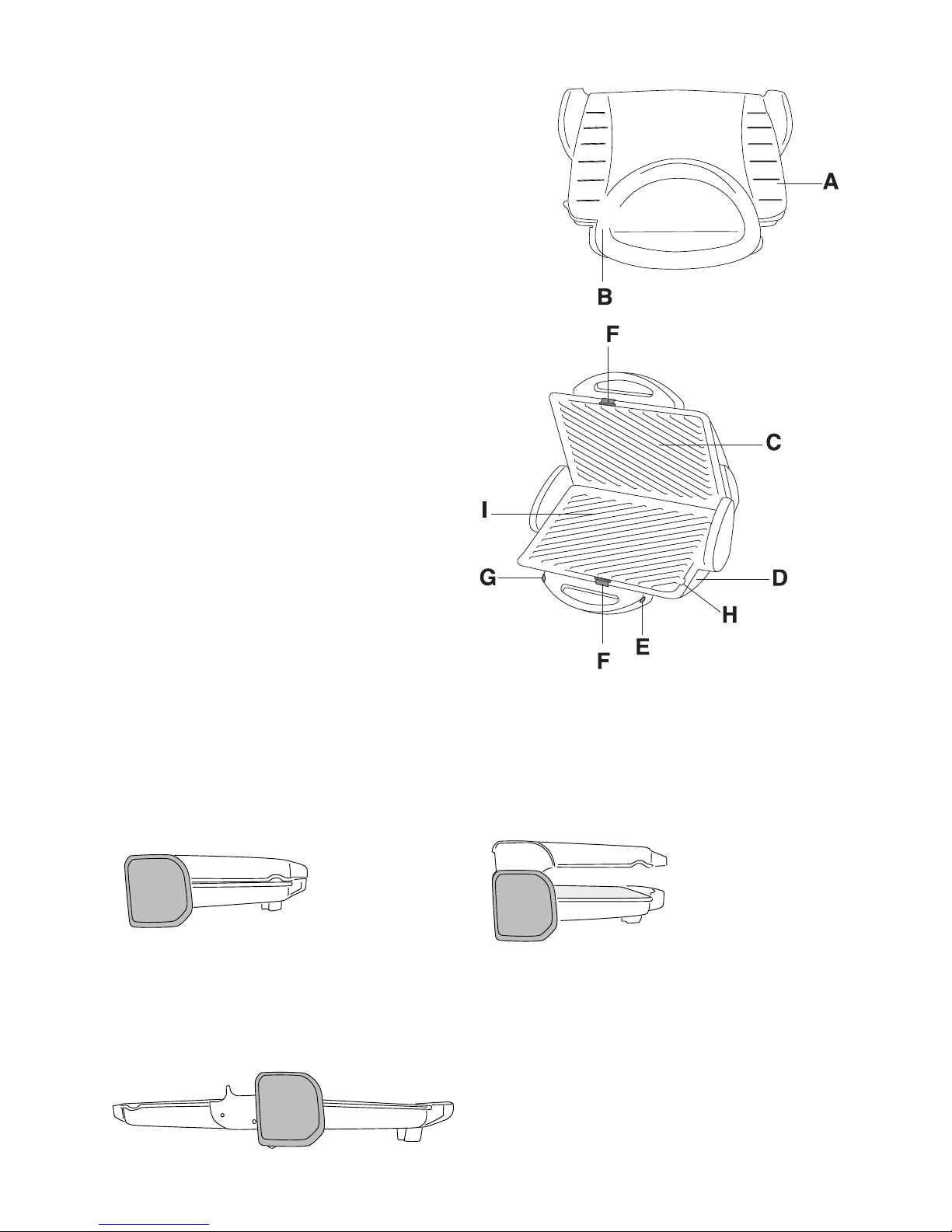
DESCRIPTION OF APPLIANCE
A Top of appliance
B Heat-insulated handle
C Top non-stick grill plate,
removable
D Base of appliance
E Temperature control knob
F Grill plate release catch
G Pilot light
H Drainage vent
I Bottom non-stick grill plate,
removable
TEILE DES GERÄTES
A Oberer Geräteteil
B Thermoisolierter Griff
C Obere antihaftbeschichtete
Wechselplatte
D Unterer Geräteteil
E Temperaturregler
F Klemme für die Plattenbefestigung
G Kontrolllampe
H Fettabfluss
I Untere antihaftbeschichtete
Wechselplatte
En
De
 Loading...