

Page 1

DVD RECEIVER
DVR-8100
INSTRUCTION MANUAL
KENWOOD CORPORATION
B60-5290-08 00 (E/T/X) WS 02/07
COMPACT
DIGITAL VIDEO
Page 2
2
Before applying power
Caution : Read this page carefully to ensure safe operation.
Units are designed for operation as follows.
U.S.A. and Canada ................ AC 120 V only
Australia ................................ AC 240 V only
Europe and U.K. ....................AC 230 V only
For the United Kingdom
Factory fitted moulded mains plug
1. The mains plug contains a fuse. For replacement,
use only a 13-Amp ASTA-approved (BS 1362) fuse.
2. The fuse cover must be refitted when replacing
the fuse in the moulded plug.
3. Do not cut off the mains plug from this equipment. If the plug fitted is not suitable for the power
points in your home or the cable is too short to reach
a power point, then obtain an appropriate safety
approved extension lead or adapter, or consult your
Preparations
dealer.
If nonetheless the mains plug is cut off, remove the
fuse and dispose of the plug immediately, to avoid
a possible shock hazard by inadvertent.
IMPORTANT :
The wires in the mains lead are coloured in accordancewith the following code:
Blue : Neutral
Brown : Live
Do not connect those leads to the earth terminal of
a three-pin plug.
DVR-8100 (EN)
China and Russia ...................AC 220 V only
Other countries ................... AC 220 - 240 V
Manufactured under license from Dolby Laboratories.
“DOLBY”, “Pro Logic” and the double-D symbol are
trademarks of Dolby Laboratories.
“DTS” and “DTS Digital Surround” are trademarks of
Digital Theater Systems, Inc.
Safety precautions
WARNING : TO PREVENT FIRE OR ELECTRIC SHOCK, DO NOT
EXPOSE THIS APPLIANCE TO RAIN OR MOISTURE.
CAUTION: TO REDUCE THE RISK OF ELECTRIC SHOCK,
CAUTION
RISK OF ELECTRIC SHOCK
DO NOT OPEN
THE LIGHTNING FLASH WITH ARROWHEAD SYMBOL, WITHIN AN EQUILATERAL TRIANGLE,
IS INTENDED TO ALERT THE USER TO THE PRESENCE OF UNINSULATED “DANGEROUS
VOLTAGE” WITHIN THE PRODUCT’S ENCLOSURE THAT MAY BE OF SUFFICIENT MAGNITUDE
TO CONSTITUTE A RISK OF ELECTRIC SHOCK TO PERSONS.
THE EXCLAMATION POINT WITHIN AN EQUILATERAL TRIANGLE IS INTENDED TO ALERT THE
USER TO THE PRESENCE OF IMPORTANT OPERATING AND MAINTENANCE (SERVICING)
INSTRUCTIONS IN THE LITERATURE ACCOMPANYING THE APPLIANCE.
The marking of products using lasers (For countries other than U.S.A., U.S.-Military and Canada)
CLASS 1
LASER PRODUCT
The marking this product has been classified as Class 1. It means that there is no
danger of hazardous radiation outside
the product.
Location: Back panel
Inside this laser product, a laser diode classified as Class 2 laser radiation is contained as
alerted by the internal caution label shown
above. Do not stare into beam.
Location: DVD laser pick-up unit cover inside
this product
CAUTION
VISIBLE LASER RADIATION
WHEN OPEN. DO NOT
STARE INTO BEAM.
DO NOT REMOVE COVER (OR BACK). NO USERSERVICEABLE PARTS INSIDE, REFER SERVICING TO
QUALIFIED SERVICE PERSONNEL.
CAUTION
INVISIBLE LASER RADIATION
WHEN OPEN. DO NOT STARE
INTO BEAM OR VIEW DIRECTLY
WITH OPTICAL INSTRUMENTS.
Inside this laser product, a laser diode classified as Class
3A laser radiation is contained as alerted by the internal
caution label shown above. Do not stare into beam or
view directly with optical instruments.
Location: CD laser pick-up unit cover inside this product
Page 3

Contents
3
DVR-8100 (EN)
Caution : Read the pages marked carefully to ensure safe operation.
Preparations
Before applying power ........................................................... 2
Safety precautions ............................................................. 2
Accessories ............................................................................... 4
IMPORTANT SAFEGUARDS .................................................... 5
Special features .............................................................................. 6
Reference ......................................................................................... 6
Maintenance .................................................................................... 7
Discs information ............................................................................ 8
Types of playable discs ........................................................... 8
Unplayable discs ...................................................................... 8
Icons on the DVD discs ............................................................ 8
Region codes ................................................................................... 9
Region codes in the world ...................................................... 9
Examples of TV screen display of each video format........ 9
Video formats ................................................................................. 10
Video formats of DVD discs that can be played on this unit......
System Connections .............................................................. 11
Loudspeakers .......................................................................... 11
AM loop antenna .................................................................... 12
FM antenna .............................................................................. 12
Connecting to a TV ................................................................. 13
Connecting to a Satellite Tuner or a Cable TV .................. 13
Connecting to Audio video equipments ............................. 14
Controls and indicators................................................................ 15
Operation of remote control unit ......................................... 16
Operations
Let's put out some sound ............................................................. 17
Basic use method ................................................................... 17
Adjusting the sound ...................................................................... 18
Selecting a LISTEN mode...................................................... 18
ACTIVE EQ. ............................................................................... 20
NIGHT mode (Dolby Digital sources only) ......................... 20
BASS and TREBLE Adjustments ........................................... 20
Adjusting the Pro Logic II MUSIC mode ............................. 21
Input Attenuator ...................................................................... 21
Display ............................................................................................ 22
Changing the display ............................................................. 22
Dimmer ..................................................................................... 22
Receiving broadcast station ....................................................... 23
Storing the broadcast stations (one-by-one presetting) . 24
Using RDS function (for Europe and U.K. only) ................. 25
PTY function (for Europe and U.K. only) ............................. 26
Playback of disc ............................................................................ 27
Basic play ................................................................................ 27
Disc playback features .......................................................... 28
Using the On-screen banner display ......................................... 29
Selecting a Title...................................................................... 30
Selecting a Chapter or Track ................................................ 30
Changing the Audio Language ............................................. 31
Changing the Subtitle Language.......................................... 31
Changing the Camera angle ................................................. 32
Using IntroScan function ...................................................... 32
Using Bookmarks ................................................................... 33
Repeat play .............................................................................. 34
A-B Repeat play ...................................................................... 34
Random play ............................................................................ 35
Program play .................................................................................. 36
Menu playback .............................................................................. 38
Hierarchical structure of VCD menus ................................. 38
Examples of operation keys and indications used during
VCD playback .................................................................... 38
Playback without using the menu playback function (In case
of a P.B.C.-compatible VCD) (To P.B.C. On or Off) .............
MP3 function .................................................................................. 40
Guidance of MP3 .................................................................... 40
Playing back MP3 ................................................................... 41
MP3 Repeat play ..................................................................... 43
MP3 Random play ................................................................... 43
MP3 Program play .................................................................. 44
Set Up functions ............................................................................ 45
Set up menu ............................................................................. 45
Select Audio Language ......................................................... 46
Select Subtitle Language ...................................................... 46
10
Select Menu Language .......................................................... 47
Select Rating ........................................................................... 47
Password ................................................................................. 48
TV aspect .................................................................................. 50
Speaker setting ............................................................................. 51
Speaker level setting ............................................................. 51
Delay time setting ................................................................... 52
Level setting using a music source..................................... 53
Changing the INPUT MODE ......................................................... 53
Control of a different device with the accessory remote
controller .................................................................................. 54
Register the setup codes for your audio and video.......... 54
Operating other devices ........................................................ 54
Setup code table ..................................................................... 55
Keys which can be used to operate connected devices 56
39
Preparations
Knowledge
Knowledge ..................................................................................... 57
DVD menu language code list .............................................. 57
In case of difficulty ....................................................................... 58
Specifications................................................................................ 61
Page 4
4
DVR-8100 (EN)
Unpacking
Unpack the unit carefully and make sure that all accessories are present.
If any accessories are missing, or if the unit is damaged or fails to operate, notify your dealer immediately. If your unit was shipped
to you directly, notify the shipper immediately.
KENWOOD recommends that you retain the original carton and packing materials in case you need to move or ship the unit in the future.
Keep this manual handy for future reference.
Accessories
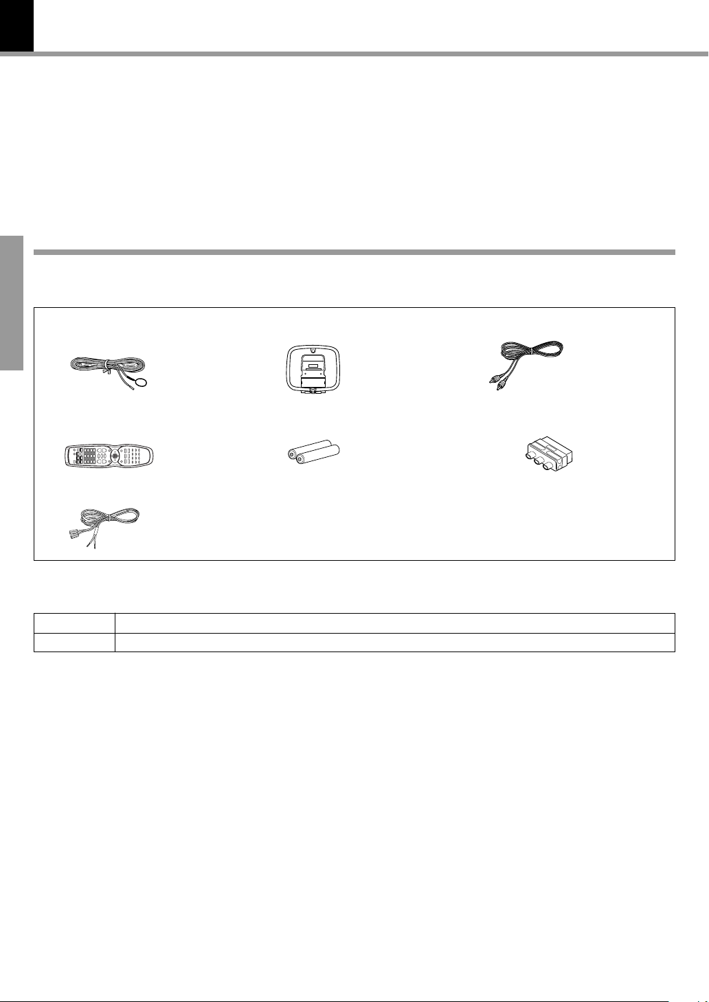
Please confirm that the following accessories are present.
Accessories packed with the main unit
FM indoor antenna (1) Loop antenna (1)
Video cord (1)
Preparations
Remote control unit (1) Batteries (R6/AA) (2)
Speaker cords (6)
SCART plug adaptor (1)
(Europe and U.K. only)
Speaker model names
System Speakers
DVR-8100 KSW-8100 (Left speaker, right speaker, center speaker, surround speakers and subwoofer)
Page 5

IMPORTANT SAFEGUARDS
Caution : Read this page carefully to ensure
safe operation.
DVR-8100 (EN)
5
Please read all of the safety and operating instructions before
operating this appliance. Adhere to all warnings on the appliance
and in the instruction manual. Follow all the safety and operating
instructions. These safety and operating instructions should be
retained for future reference.
1. Power sources – The appliance should be connected to a
power supply only of the type described in the instruction
manual or as marked on the appliance. If you are not sure of
the type of power supply to your home, consult your appliance
dealer or local power company. For appliances intended to
operate from battery power, or other sources, refer to the
instruction manual.
2. Power-cord protection – Power-supply cords should be
routed so that they are not likely to be walked on or pinched by
items placed upon or against them, pay particular attention to
cords at plugs, convenience receptacles, and the point where
they exit from the appliance.
3. Ventilation – Slots and openings in the cabinet are provided
for ventilation and to ensure reliable operation of the appliance
and to protect it from overheating, and these openings must
not be blocked or covered. The appliance should be situated so
that its location or position does not interfere with its proper
ventilation.
To maintain good ventilation, do not put records or a table-cloth
on the appliance. Place the appliance at least 10 cm away from
the walls.
Do not use the appliance on a bed, sofa, rug or similar surface
that may block the ventilation openings. This appliance should
not be placed in a built-in installation such as a bookcase or rack
unless proper ventilation is provided or the manufacturer’s
instructions have been adhered to.
4. Water and moisture – The appliance shall not be exposed to
dripping and splashing - for example, near a bathtub, washbowl,
kitchen sink, laundry tub, in a wet basement, or near a
swimming pool, etc. Do not place an object containing liquid,
such as a flower vase, on the appliance.
5. Temperature – The appliance may not function properly if
used at extremely low, or freezing temperatures. The ideal
ambient temperature is above +5°C (41°F).
6. Heat – The appliance should be situated away from heat
sources such as radiators, heat registers, stoves, or other
appliances (including amplifiers) that produce heat. Do not
place a flaming object, such as a candle or lantern, on or near
the appliance.
7. Electric shock – Care should be taken so that objects do not
fall and liquid is not spilled into the enclosure through openings.
If a metal objects, such as a hair pin or a needle, comes into
contact with the inside of this appliance, a dangerous electric
shock may result. For families with children, never permit
children to put anything, especially metal, inside this appliance.
8. Enclosure removal – Never remove the enclosure. If the
internal parts are touched accidentally, a serious electric shock
might occur.
10. Lightning – For added protection for this appliance during a
lightning storm, or when it is left unattended and unused for
long periods of time, unplug it from the wall outlet and
disconnect the antenna or cable system. This will prevent
damage to the appliance due to lightning and power-line
surges.
11. Abnormal smell – If an abnormal smell or smoke is detected,
immediately turn the power OFF and unplug the appliance
from the wall outlet. Contact your dealer or nearest service
center.
12. Damage requiring service – The appliance should be serviced
by qualified service personnel when:
A. The power-supply cord or the plug has been damaged.
B. Objects have fallen, or liquid has been spilled into the
appliance.
C. The appliance has been exposed to rain or water.
D. The appliance does not appear to operate normally by
following the instruction manual. Adjust only those controls
that are covered by the instruction manual as an improper
adjustment of other controls may result in damage and will
often require extensive work by a qualified technician to
restore the appliance to its normal operation.
E. The appliance has been dropped, or the enclosure
damaged.
F. The appliance exhibits a marked change in performance.
13. Servicing – The user should not attempt to service the
appliance beyond that described in the instruction manual. All
other servicing should be referred to qualified service personnel.
14. Power lines – An outside antenna system should not be
located in the vicinity of overhead power lines or other electric
light or power circuits, or where it can fall into such power lines
or circuits. When installing an outside antenna system, extreme
care should be taken to keep from touching such power lines
or circuits as contact with them might be fatal.
15. AC outlets – Do not connect other audio equipment with a
power consumption larger than that specified to the AC outlet
on the rear panel. Never connect other electrical appliances,
such as an iron or toaster, to it to prevent fire or electric shock.
16. Overloading – Do not overload wall outlets, extension cords,
or integral convenience receptacles as this can result in a risk
of fire or electric shock.
17. Attachment – Do not use attachments not recommended by
the appliance manufacturer as they may cause hazards.
18. Replacement parts – When replacement parts are required,
be sure the service technician has used replacement parts
specified by the manufacturer or have the same characteristics
as the original parts. Unauthorized substitutions may result in
fire, electric shock, or other hazards.
19. Safety check – Upon completion of any service or repairs to
this appliance, ask the service technician to perform safety
checks to determine that the appliance is in proper operating
condition.
Preparations
9. Cleaning – Unplug this appliance from the wall outlet before
cleaning. Do not use volatile solvents such as alcohol, paint
thinner, gasoline, or benzine, etc. to clean the cabinet. Use a
clean dry cloth.
Page 6
6
Special features
Special features
This document classifies the applications of each feature using the following marks
: Description of a feature that can be used with DVD.
DVD
: Description of a feature that can be used with CD.
CD
: Description of a feature that can be used with VCD.
VCD
DVD
Higher video quality than S-VHS video and LaserDisc
DVD
Higher audio quality than music CD
CD
DVD
VCD
Graphical user interface (GUI) compatibility
DVR-8100 (EN)
Preparations
DVD
DVD
CD
DVD
Versatile DVD playback features
CD
The DVR-8100 offers DTS decoder.
VCD
Dolby Pro Logic II decoder.
Reference
Caution on condensation
Condensation (of dew) may occur inside the unit when there is
a great difference in temperature between this unit and the
outside.
This unit may not function properly if condensation occurs. In
this case, leave the unit for a few hours, and restart the operation after the condensation has dried up.
Be specially cautious against condensation in a following
circumstances:
When this unit is carried from one place to another across a
large difference in temperature, when the humidity in the room
where this unit is installed increases, etc.
Memory backup function
Stored contents which are
cleared in at least a week
after power plug is unplugged from power outlet.
Amplifier section
Last input selection
Volume control value
Surround setting
ACTIVE EQ
Tuner section
Receiving band
Frequency
Preset stations
Tuning mode setting
DVD section
Menu setup
Power status
Note related to transportation and movement
Before transporting or moving this unit, carry out the
following operations.
1 Remove the disc from the unit.
2 Press the 6 key.
DIGITAL
AUTO ST.
CS DTS
SEQ112
DVD DIRECT
DVD AUDIO
RDM
PGM
DVD VIDEO
A-B
AUTO DETECT
TITLE
ACTIVE EQ
P.B.C.
CHAP
RDS
TRACK
SOUND EQ
3 Wait a few seconds and turn the unit OFF.
TUNED CLIP
DSP
Pro Logic
kHz fs192
kHz
kHz
MHz
LC
fs96
LS RS
R
LFESW
S
Page 7
Maintenance
7
DVR-8100 (EN)
Maintenance of the Set
When the front panel, the case, etc. becomes dirty, wipe with
a soft, dry cloth. Do not use thinner, alcohol, etc., as these can
cause discoloration.
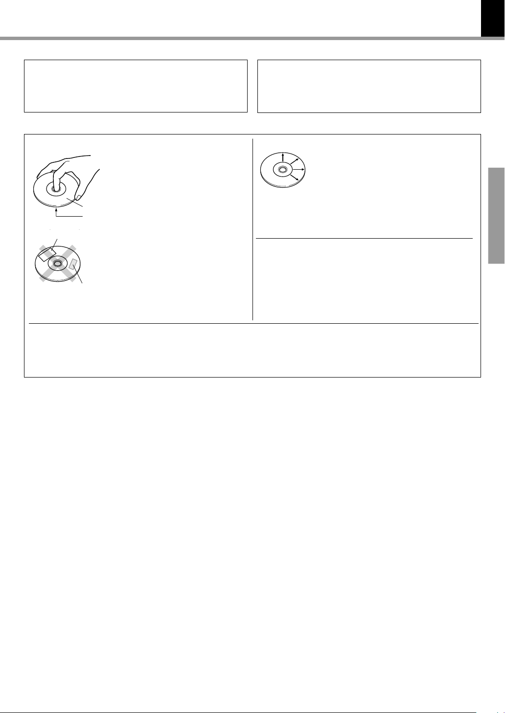
Disc handling precautions
Handling
Hold the discs so that you do not
touch the playing surface.
Label side
Playing side
Sticker
Do not attach paper or tape to either
the playing side or the label side of the
discs.
Sticky paste
In regard to contact cleaners
Do not use contact cleaners because it could cause a malfunction. Be specially careful not to use contact cleaners containing oil, for they may deform the plastic component.
Cleaning
If fingerprints or foreign matter become attached to the disc, lightly wipe the disc with a
soft cotton cloth (or similar) from the center of
the disc outwards in a radial manner.
Storage
When a disc is not to be played for a long period
of time, remove it from the player and store it
in its case.
Never play a cracked or warped disc
During playback, the disc rotates at high speed in the player.
Therefore, to avoid danger, never use a cracked or deformed
disc or a disc repaired with tape or adhesive agent.
Please do not use discs which are not round because they may
cause a malfunction.
Disc accessories
The disc accessories (stabilizer, protection sheet, protection ring, etc.) which are marketed for improving the sound quality or
protecting discs as well as the disc cleaner should not be used with this system because they may cause malfunction.
Preparations
Page 8
8
Discs information
DVR-8100 (EN)
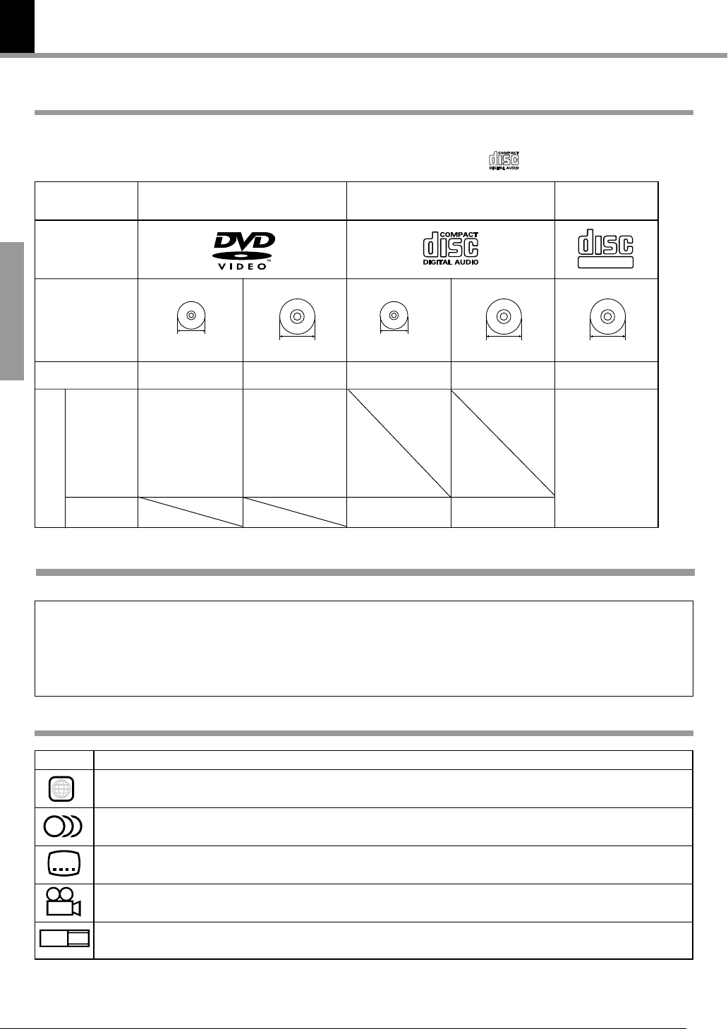
Types of playable discs
The system using this unit does not only play music from CD but can also play the discs listed below to offer you
high-quality entertainment of video of movies and live concerts.
Use discs that comply with the IEC standard, for example a disc carrying the
marking on the label surface.
Playable Disc
Logo mark on disc
Disc size
Preparations
Played sides
Contents
Video + Audio
8cm
One or both One or both
Approx. 41 min.
(1 side, 1 layer)
Approx. 75 min.
(1 side, 2 layers)
Approx. 82 min.
(2 sides, 1 layer)
Approx. 150 min.
(2 sides, 2 layers)
Audio
DVD CD (CD-DA)
12cm
Approx. 133 min.
(1 side, 1 layer)
Approx. 242 min.
(1 side, 2 layers)
Approx. 266 min.
(2 sides, 1 layer)
Approx. 484 min.
(2 sides, 2 layers)
Unplayable discs
This player cannot play back any of the following discs.
8cm
One side only One side only
Max. 20 min., digital Max. 74 min., digital
12cm
VCD
COMPACT
DIGITAL VIDEO
12cm
One side only
Max. 74 min.
÷ DVD-ROM discs
÷ DVD-R/DVD-RAM/DVD-RW discs
÷ VSD discs
÷ CDV discs (only the audio part can be reproduced.)
÷ CD-ROM discs (except MP3 (ISO 9660 level 1 format)
disc.)
Icons on the DVD discs
Icon Description
ALL
8
32
9
16:9 LB
Indicates the region code where the disc can be played.
Number of voice languages recorded with the audio function. The number in the icon indicates the number of voice languages.
(Max. 8 languages)
Number of subtitle languages recorded with the subtitle function. The number in the icon indicates the number of subtitle
languages. (Max. 32 languages)
Number of angles provided by the angle function. The number in the icon indicates the number of angles. (Max. 9 angles)
Aspect ratios that can be selected. “LB” stands for Letter Box and “PS” for Pan/Scan. In the example on the left, the 16:9 video
can be converted into letter box video.
÷ CD-G/CD-EG/CD-EXTRA discs (only the audio can be
reproduced.)
÷ Photo CD discs (never attempt to play them.)
÷ S-VCD discs
Page 9
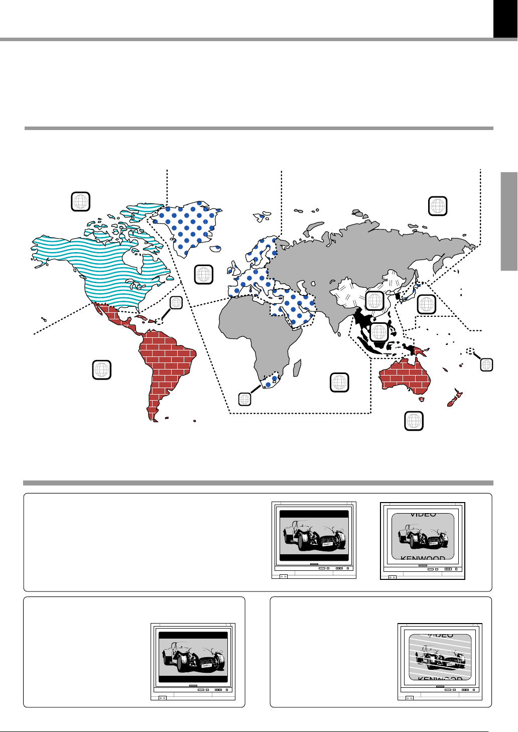
Region codes
DVR-8100 (EN)
Every player of this model has a certain region code assigned to it based on the country where the player is used.
When the player is used to play back DVD discs, it can only play the DVD discs carrying the region codes matching
the region code of the player.
The region code for this player is described on the rear panel of the player.
Region codes in the world
The DVD players are given a region code according to the country or area it is marketed, as shown in the following
map.
1
2
5
9
Preparations
1
6
3
4
5
2
Examples of TV screen display of each video format
When your TV is switchable between PAL/
NTSC
Try play a disc. If the picture is black and white or as shown on the right,
stop playback and switch the screen display formats of this unit and the
TV to another format. This will improve the played picture quality.
2
1
4
When your TV is compatible only with the
PAL format
With certain discs, the playback picture may have black spaces above
and below it (as shown on the right).
This is because the disc has been
recorded in the NTSC format. The
screen may be somewhat hard to
see but this is not malfunction.
When your TV is compatible only with the
NTSC format
With certain discs, the playback picture may be cut above and below it
(as shown on the right). This is because the disc has been recorded in
the PAL format. The screen may be
somewhat hard to see but this is not
malfunction.
Page 10
10
3
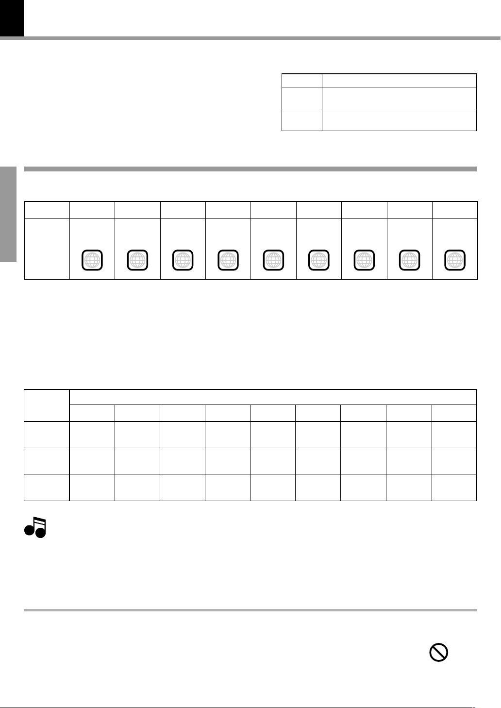
Video formats
DVR-8100 (EN)
The video signals used to display TV pictures and video
disc pictures are mainly based on two types of signal
formats (PAL and NTSC), which are assigned to each
country or area as shown on the right. As a result, it is
required to select discs according to the video format
used with your TV monitor (in your country or area).
TV formats of major countries
TV Format
NTSC
PAL
Japan, Taiwan, Korea, U.S.A., Canada, Mexico,
Philippines, Chile, etc.
China, U.K., Germany, Australia, New Zealand,
Kuwait, Singapore, etc.
Major Countries & Areas
Video formats of DVD discs that can be played on this unit
Region code table
District 1
Area or
Country
Preparations
Name,
Region
Code
North
America
Set the video formats of the DVD discs to be played on this unit as described below.
Check the video format(s) used by your TV monitor.
1
÷ Refer to the operating instructions of your TV monitor for details.
District 2-1
Europe
District 2-2
Japan
District 2-3
Middle East
1 2 2 2
District 3
Southeast
Asia
District 4-1
Oceania
4
District 4-2
South
America
District 5
4 5 6
Russia
District 6
China
Select DVD discs recorded with the playable video format by referring to the following table.
2
÷ See the region code table on this page for details on districts 1 to 6.
Your TV
format
NTSC only
PAL only
NTSC/PAL
switchable
Note
Note
When your TV is switchable between NTSC and PAL,
3
District 1
NTSC
NTSC*
NTSC
Normal video may not be reproduced when a disc recorded with the video format marked * in the above table is played. See “Examples of TV
screen display of each video format” for details. 9
÷ Districts 1, 2-2 and 4-2: Set the TV to NTSC.
÷ Districts 2-1, 4-1 and 5: Set the TV to PAL.
÷ Districts 2-3, 3 and 6: Set the TV according to each disc to be played.
District 2-1
NTSC
PAL*
NTSC*
PAL
NTSC
PAL
District 2-2
NTSC
NTSC*
NTSC
Playable Disc Formats
District 2-3
NTSC
PAL*
NTSC*
PAL
NTSC
PAL
District 3
NTSC
PAL*
NTSC*
PAL
NTSC
PAL
District 4-1
NTSC
PAL*
NTSC*
PAL
NTSC
PAL
District 4-2
NTSC
NTSC*
NTSC
District 5
NTSC
PAL*
NTSC*
PAL
NTSC
PAL
Restrictions due to difference between discs
Some DVD discs can be played only in certain playback modes according to the intentions of the software
producers. As this player plays discs according to their intentions, some functions may not work as
intended by you. Please be sure to read the instructions provided with each disc. When an inhibition icon
is displayed on the TV screen connected to the player, it indicates that the disc being played is under the
restriction as described above.
Inhibition icon
District 6
NTSC
PAL*
NTSC*
PAL
NTSC
PAL
Page 11
System Connections
Make connections as shown below.
When connecting the related system components, refer also
to the instruction manuals of the related components.
Caution : Read this page carefully to ensure
safe operation.
Caution:
DVR-8100 (EN)
Do not plug in the power lead until all connections are completed.
11
Caution
Be sure to adhere followings. Or proper ventilation will be blocked causing damage
or fire hazard.
÷ Do not place any objects impairing heat radiation onto the top of unit.
÷ Leave a space around the unit (from the largest outside dimension including
projection) equal or greater than, shown below.
Top panel : 50 cm Side panel : 10 cm Back panel : 10 cm
The power in this equipment will not be completely cut off from
the AC wall outlet when the main switch is turned OFF.
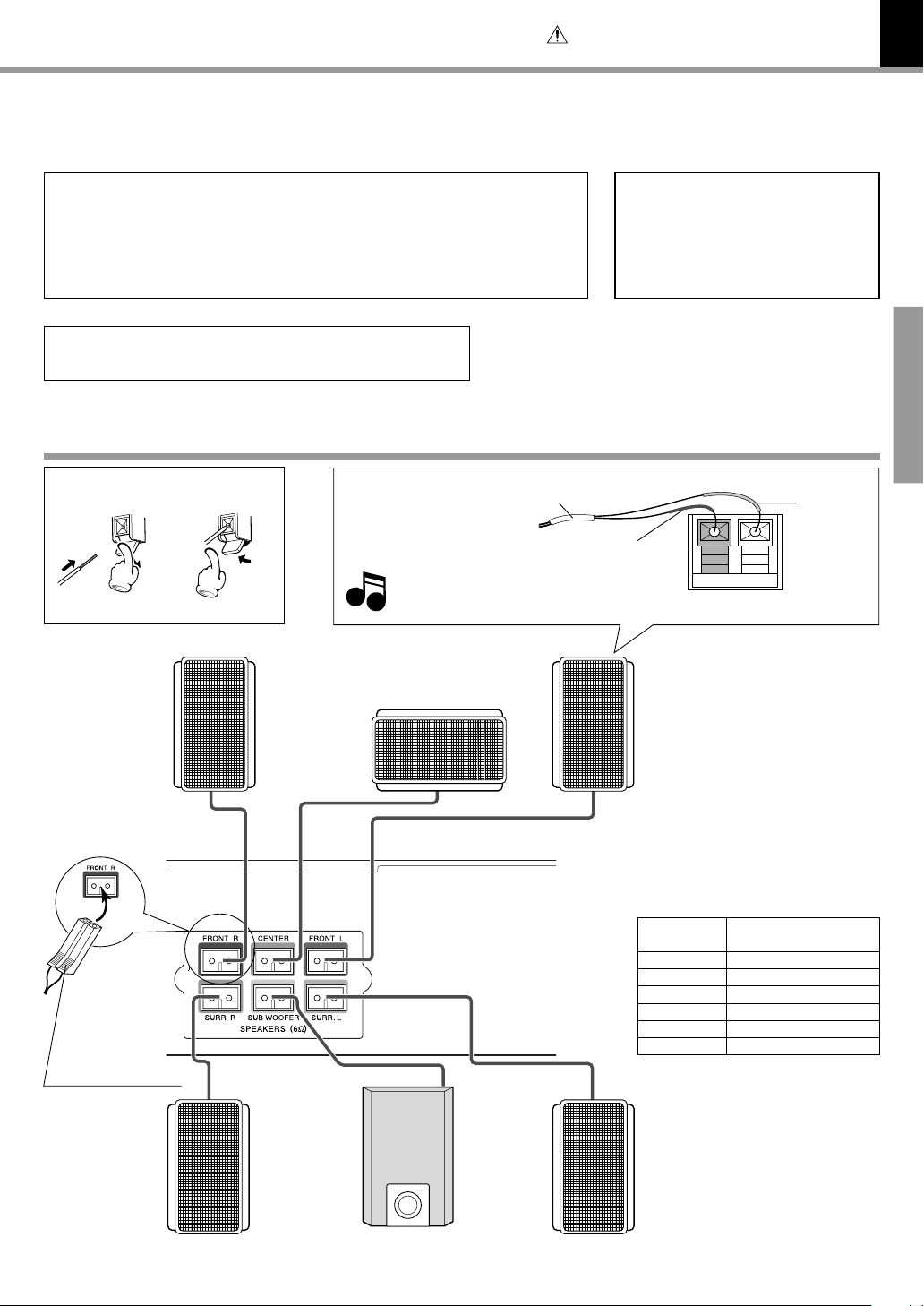
Loudspeakers
Speaker terminal
12
Front
speaker
R
Excessive insertion of the cable can
Note
Note
cause defective contact.
Center speaker
Color tube
Malfunction of microcomputer
If operation is not possible or erroneous
display appears even though all connections have been made properly, reset the
microcomputer referring to “In case of
difficulty”. I
Preparations
White
tube
Black tube
Front
speaker
L
Upper side mark
Surround
speaker
R
Subwoofer
Connect the speaker cable terminals
to the terminals with the same color
at the speaker terminal panel on the
main unit. Connect matching the
color of the speaker terminal (+ side)
and the color of the speaker cable
tube.
Speaker
Front right
Center
Front left
Surround right
Subwoofer
Surrond left
Surround
speaker
L
Color of the speaker terminal panel on the main unit
Red
Green
White
Gray
Purple
Blue
Page 12
12
(
(
ANTENNA
Caution : Read this page carefully to ensure safe operation.
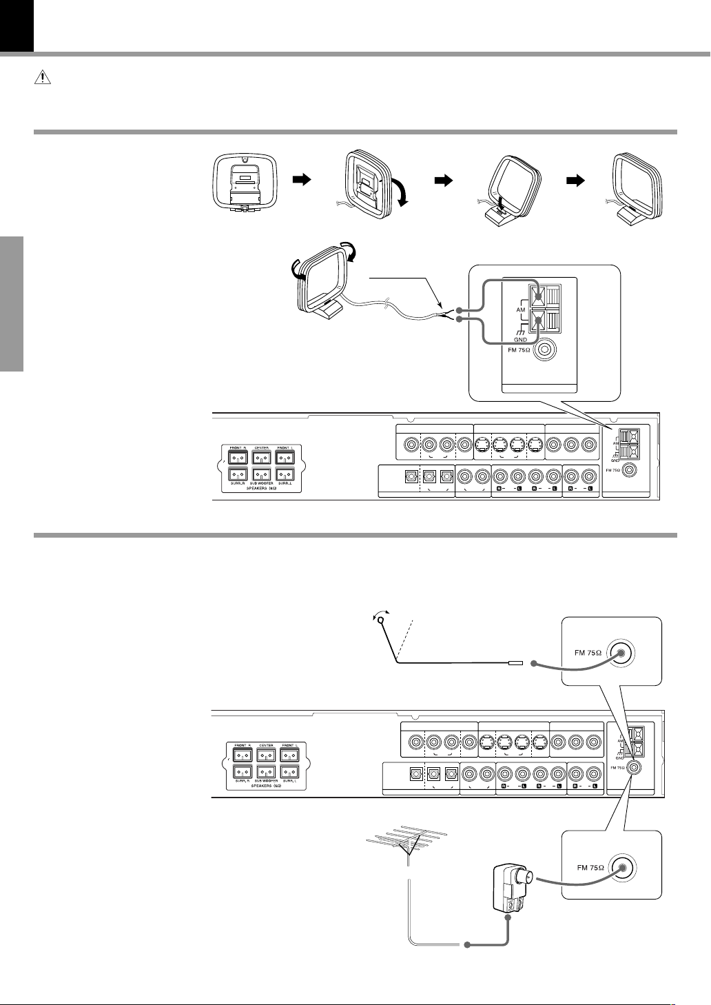
AM loop antenna
AM loop antenna connection
The supplied antenna is
for indoor use. Place it as
far as possible from the
main system, TV set,
speaker cords and power
cord, and set it to a direction which provides the
Preparations
best reception.
System Connections
DVR-8100 (EN)
White
FM antenna
FM indoor antenna connection
The accessory antenna is
for temporary indoor use
only. For stable signal reception we recommend
using an outdoor antenna.
Remove the indoor antenna if you connect one
outdoors.
FM outdoor antenna
(commercially available)
Lead the 75 Ω coaxial cable
connected to the FM outdoor antenna into the room
and connect it to the FM 75
Ω terminal.
IN INOUT
OUT
MON. MON.
VCR
BIT STREAM
/PCM
DIGITAL
SAT/CABLEVCR
OUT
DIGITAL IN
1 Connect to the antenna terminal.
2 Locate the position providing good
reception condition.
3 Fix the antenna.
IN INOUT
OUT
MON. MON.
VCR
BIT STREAM
(
(
/PCM
DIGITAL
SAT/CABLEVCR
OUT
DIGITAL IN
CABLE
VCR
SAT/
DIGITAL IN
SAT/
CABLE
VCR
SAT/CABLE
SAT/CABLE
DIGITAL IN
S-VIDEOVIDEO
OUT
VCR
S-VIDEOVIDEO
OUT
VCR
DVD COMPONENT
IN INOUT
VIDELO OUT
SAT/
CABLE
INOUT
VCRCOAXIALOPTICAL
IN INOUT
SAT/
CABLE
VCRCOAXIALOPTICAL
DVD COMPONENT
VIDELO OUT
INOUT
YC
BCR
IN
ANTENNASAT / CABLE
YC
BCR
IN
ANTENNASAT / CABLE
Page 13
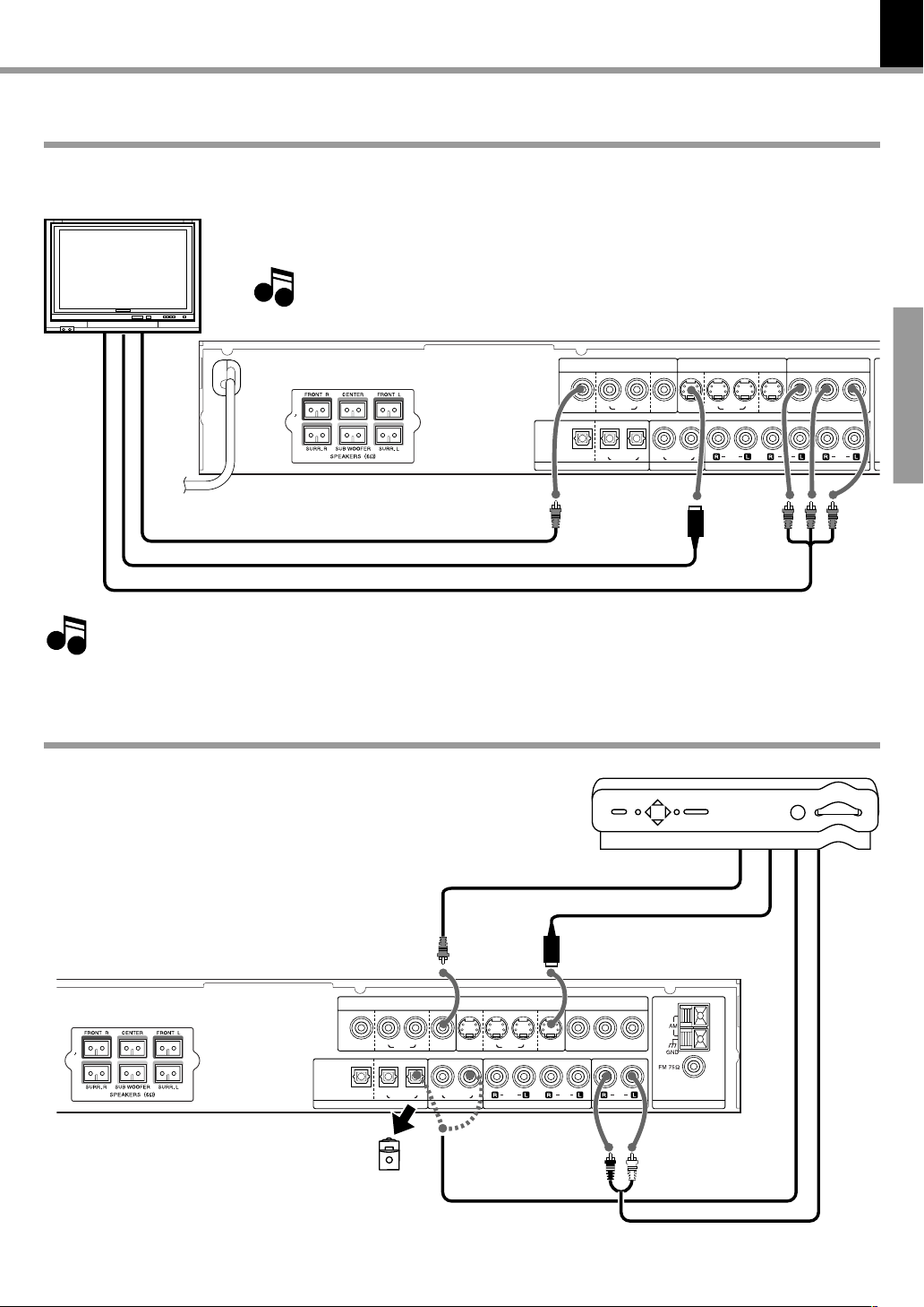
Connecting to a TV
Depending on the input switching, the output from the MONITOR OUT terminal will be one of the
following signals. Please note that a different signal type will not be put out.
TV
*COMPOSITE Video cord (accessory)
S-Video cord
COMPONENT Video cord
S-VIDEO terminal : S-video signals from the internal DVD player, from the component connected to
VIDEO terminal : Composite video signals from the internal DVD player, from the component
Note
Note
System Connections
the (VIDEO) VCR IN or the (VIDEO) SAT/CABLE terminal.
connected to the (VIDEO) VCR IN or the (VIDEO) SAT/CABLE terminal.
If you hear noise form the connected TV, install it apart from the unit.
SAT/CABLE
DIGITAL IN
S-VIDEOVIDEO
OUT
VCR
OUT
MON. MON.
BIT STREAM
(
(
/PCM
DIGITAL
OUT
DIGITAL IN
IN INOUT
SAT/
VCR
CABLE
VCR
SAT/CABLEVCR
13
DVR-8100 (EN)
Preparations
DVD COMPONENT
SAT/
CABLE
VIDELO OUT
YC
BCR
INOUT
IN
SAT / CABLE
IN INOUT
VCRCOAXIALOPTICAL
Regarding COMPONENT connection
When the TV has a COMPONENT terminal, the DVD image will be played
Note
Note
back with higher picture quality using COMPONENT connection.
In this case connect the S-video or the COMPOSITE video cord as well.
Connecting to a Satellite Tuner or a Cable TV
COMPOSITE video cord
S-Video cord
OUT
MON. MON.
VCR
BIT STREAM
(
(
/PCM
DIGITAL
SAT/CABLEVCR
OUT
DIGITAL IN
SAT/CABLE
DIGITAL IN
S-VIDEOVIDEO
OUT
IN INOUT
VCR
IN INOUT
SAT/
CABLE
VCR
DVD COMPONENT
VIDELO OUT
SAT/
CABLE
INOUT
VCRCOAXIALOPTICAL
* For Europe and U.K. only
If your TV set has a SCART terminal,
connect the accessory SCART plug to the
SCART terminal of the TV and connect
the COMPOSITE video cord.
Satellite tuner/Cable TV
YC
BCR
IN
ANTENNASAT / CABLE
Remove the protective cap
before using the jack
OPTICAL or COAXIAL
cable
Audio cord
Page 14

14
Connecting to Audio video equipments
In case of digital recording with an MD
recorder or a CD recorder
OPTICAL cable
Note
Note
This unit's digital out does not convert DVD bit stream data to
PCM format. When playing Dolby Digital or DTS format DVDs,
bit stream data is output from the digital out. To make digital
recordings, play PCM format discs.
Analog recording of DTS-encoded discs is not possible.
System Connections
DVR-8100 (EN)
Preparations
When DIGITAL OUT signal is PCM format
SAT/CABLE
DIGITAL IN
S-VIDEOVIDEO
OUT
IN INOUT
SAT/
VCR
CABLE
VCRCOAXIALOPTICAL
OUT
MON. MON.
VCR
BIT STREAM
(
(
/PCM
DIGITAL
SAT/CABLEVCR
OUT
DIGITAL IN
IN INOUT
SAT/
CABLE
VCR
Audio
cords
OPTICAL or
COAXIAL
cable
VCR
DVD COMPONENT
VIDELO OUT
YC
BCR
INOUT
IN
S-Video cords
S-Video cords
ANTENNASAT / CABLE
COMPOSITE
video cord
COMPOSITE
video cord
Page 15
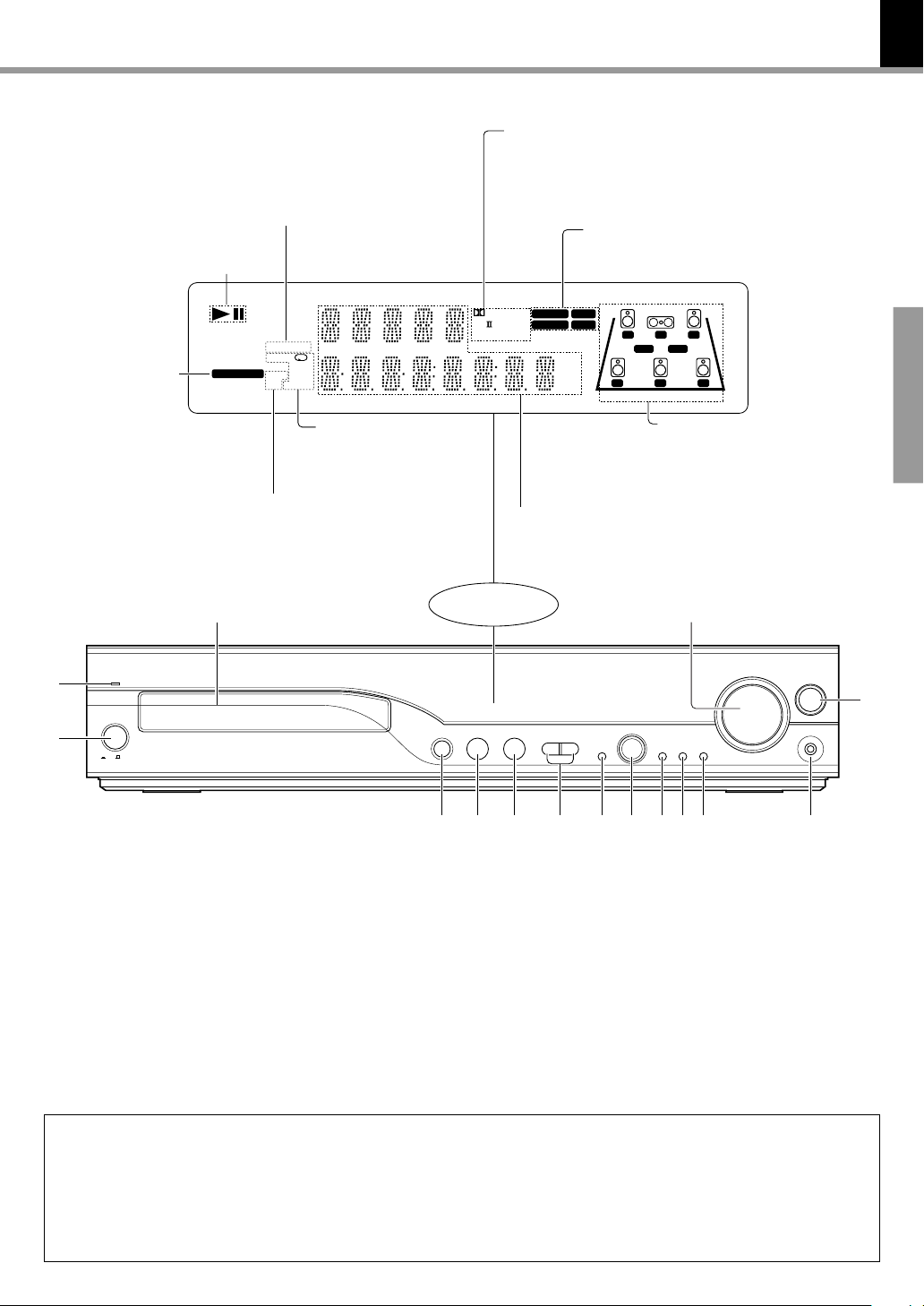
Controls and indicators
RDM (Random) indicator
PGM (Program) indicator
PLAY/PAUSE indicator
SEQ 112
DVD DIRECT
DVD AUDIO
RDM
ACTIVE EQ
indicator
DVD VIDEO
AUTO DETECT
ACTIVE EQ
SOUND EQ
A-B
P.B.C.
RDS
PGM
TITLE
CHAP
TRACK
DOLBY DIGITAL indicator
CS II indicator
DTS indicator
DSP indicator
Pro Logic indicator
AUTO indicator
TUNED indicator
ST. (Stereo) indicator
CLIP indicator
DIGITAL
Pro Logic
AUTO ST.
TUNED CLIP
kHz fs192
kHz
kHz
MHz
fs96
CS DTS
DSP
LC
LS RS
R
LFESW
S
15
DVR-8100 (EN)
Preparations
1
2
repeat indicators
1 repeat
A-B repeat
TITLE repeat
P.B.C. indicator
RDS indicator
CHAP (Chapter) repeat
TRACK repeat
(only for Europe
and U.K.)
STANDBY
POWER
OFF
ON
1 STANDBY indicator %
2 POWER switch &
3 0 (open/close) key ¶
4 6 (play/pause) key ¶
5 7 (stop) key ¶
6 4, ¢ (Skip) keys £•
7 ACTIVE EQ key )
8 MULTI CONTROL Up (5), Down (∞),
Right (3) and Left (2)/ENTER key
ªflwt
IN/OUT status indicator
L : Left speaker
C : Center speaker
R : Right speaker
LFE : Low Frequency Effect
SW : Subwoofer
LS : Left surround speaker
S : Surround speakers
RS : Right surround speaker
$%
5
23
MULTI CONTROL
∞
÷
ENTER
/
TOP MENU
MENU
Display
0
Character
information
display section
£
/
8
7
6
SKIP
ACTIVE EQ
¢4
7 8 90 ! @3 4 5
9 MENU key t
0 TOP MENU key ¶
! ON SCREEN key ª
@ PHONES jack &
# INPUT key &
$ VOLUME CONTROL knob &
% Disc tray ¶
ON SCREEN
VOLUME CONTROL
VOLUME CONTROL
INPUT
PHONES
#
STANDBY
The STANDBY indicator lights when the power cable is plugged into an outlet and the POWER switch is set to ON. While the
standby indicator is lit, a small amount of power is supplied to the system to back up the memory. When the POWER key on the
remote control unit is pressed in STANDBY status, the STANDBY indicator goes out and the main unit reaches operation status.
When the POWER switch is set to OFF in operation status, the unit will return to operation status when the POWER switch is set
to ON again. When the POWER switch is set to OFF in STANDBY status, the unit will return to STANDBY status when the POWER
switch is set to ON again.
Page 16
16
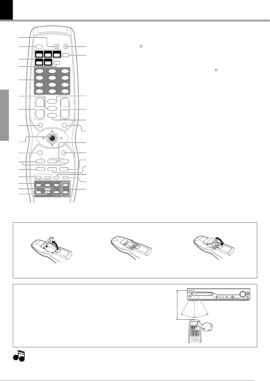
Operation of remote control unit
The keys on the remote control unit with the same names as on the
1
2
3
4
5
6
7
8
Preparations
9
0
!
@
#
$
%
^
SOURCE
0+100
SET
AUDIO
MUTE
TV INPUT
ENTER
REAR
SAT
TV
SW
POWER
INPUT MODE
RANDOM
321
654
987
CLEAR
+10
+
REPEAT
A-B
–
ON SCREEN
RDS
¢34
87¶
STEPSLOW
5
TRIM
∞
DISPLAY
TUNER
DVD/CD
BAND
CABLEVCR
PGM
+
VOLUME CH.
–
TOP MENU/P.B.C. MENU/PTY
RETURN
P.CALL
S.TITLE AUTO/MONO PRESET
REC
TUNE/TV VOL.
¡1
CENTER
FRONT
SETUP
Active EQ./Listen mode
SOUND
&
*
(
)
¡
™
£
¢
∞
§
¶
•
ª
main unit have the same function as the keys on the main unit.
1 SOURCE key RY
2 DISPLAY key ™
3 INPUT SELECTOR keys &
4 TV key Y
5 Numeric keys (0 - 9, +10,+100)
¢•ºwRY
PGM key flr
CLEAR key r
6 MUTE key &
7 VOLUME keys &
8 TOP MENU key ¶
/P.B.C. key ·
9 Cursor Up (5), Down (∞),
Left (2) and Right (3) keys
ENTER key
0 RETURN key ·t
! 4 / ¢ (Skip) keys
P.CALL keys £•
@ ¶ REC (record) key Y
S.TITLE key ⁄
# 1 / ¡ (Search) keys •
/ TUNE keys £
/ TV. VOL. keys Y
*+10 and +100 keys are not used for this
model.
ªflwt
$ Speaker select keys E
% Listen mode key *¡
^ Active EQ./SOUND key )
SETUP key Q
*
& POWER
key ^
* INPUT MODE / RANDOM key
( SET / AUDIO key Y
) CH. UP / DOWN keys Y
REPEAT / A-B keys ›e
¡ TV INPUT key Y
™ MENU key t
PTY key (U.K. and Europe only)
£ 3 (play) key ¶
¢ ON SCREEN key ª
RDS key (U.K. and Europe only)
∞ 8 (pause) key ¶
PRESET key ¢
§ 7 (stop) key ¶
AUTO/MONO key £
¶ SLOW key •
• STEP key •
ª TRIM / Up (5), Down (∞) keys
DVR-8100 (EN)
Efie
§
∞
*)Q
Model : RC-R0817E (for Europe and U.K.), RC-R0817 (for other countries)
Infrared ray system
Loading batteries
2 Insert batteries. 3 Close the cover.1 Remove the cover.
÷ Insert two R6 (“AA”) batteries follow-
ing the polarity indications.
Operation
Insert the power plug into a power outlet, press the POWER
switch of the main unit to ON, then press the POWER key
on the remote control.
÷ When pressing more than one remote control keys successively,
press the keys securely by leaving an interval of 1 second or more
between pressing of keys.
1. The provided batteries are intended for use in operation checking, and their service life may be short.
2. When the remote controllable distance becomes short, replace both of the batteries with new ones.
Notes
Notes
3. If direct sunlight or the light of a high- frequency fluorescent lamp (inverter type, etc.) is incident to the remote sensor, malfunction may occur.
In such a case, change the installation position to avoid malfunction.
Remote sensor
6m
Operating range (approx.)
30º
30º
Page 17
Let's put out some sound
Note
Note
17
DVR-8100 (EN)
Preparation
MAIN UNIT
POWER
ON
OFF
÷ set the POWER switch to the ON ( ) position.
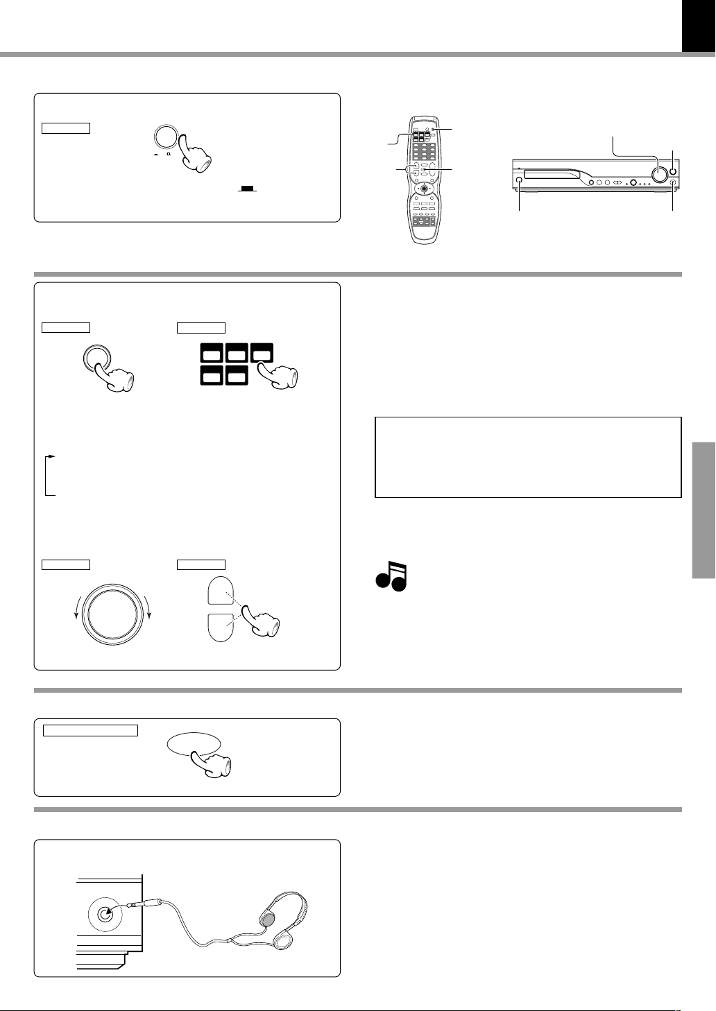
Basic use method
Selecting the desired input
1
MAIN UNIT
INPUT
Switching is done as follows when the INPUT key of the
main unit is pressed. (The parenthesized part shows an
operating example.)
1 Tuner (frequency display)
2 VCR (ANALOG or COAXIAL or OPTICAL)
3 SAT/CABLE (ANALOG or COAXIAL or OPTICAL)
4 DVD/CD
Volume adjustment
2
MAIN UNIT
To decrease To increase
VOLUME CONTROL
REMOTE
DVD/CD
REMOTE
+
VOLUME
–
TUNER
BAND
CABLEVCR
To increase
To decrease
SAT
POWER
INPUT
SELECTOR
VOLUME
÷ When one of the keys on the left is pressed while STANDBY
mode, the power will be switched on automatically and the input
will be selected.
÷ The power will be switched on and the respective operation will
be performed also when the
pause) key is pressed during STANDBY mode.
÷ When a disc is set in the disc tray and the DVD/CD key is pressed,
disc playback will start automatically.
In case of operation with the remote control unit, first select
the input or device to be operated with the INPUT SELECTOR keys then perform the desired operation.
The present mode of the remote control unit may not
coincide with the equipment to be operated.
÷ When using the remote to select SAT or CABLE;
SAT (ANALOG or COAXIAL or OPTICAL)
CABLE (ANALOG or COAXIAL or OPTICAL)
Normally "MAX" is displayed when the volume settings set to
the maximum value.
If you have adjusted the speaker level above 0db with the
TRIM key, (Q), "MAX" will not be displayed.
MUTE
POWER
00
0(open/close) key or the
00
The input mode can be switched with VCR and
SAT/CABLE. Refer to “Changing the INPUT MODE”
VOLUME CONTROL
66
6(play/
66
INPUT
PHONES
Operations
E
Muting the sound temporarily
Remote control unit only
MUTE
Listening through headphone
Insert the headphone plug into the PHONES jack.
PHONES
÷ Press the MUTE key.
÷ Press again to resume the original volume.
÷ The sound muting is also cancelled when the volume is
controlled.
This unit offers various surround modes, but it switches automatically to stereo mode when headphones are connected.
÷ The sounds from all speakers are cut off.
Page 18
18
Adjusting the sound
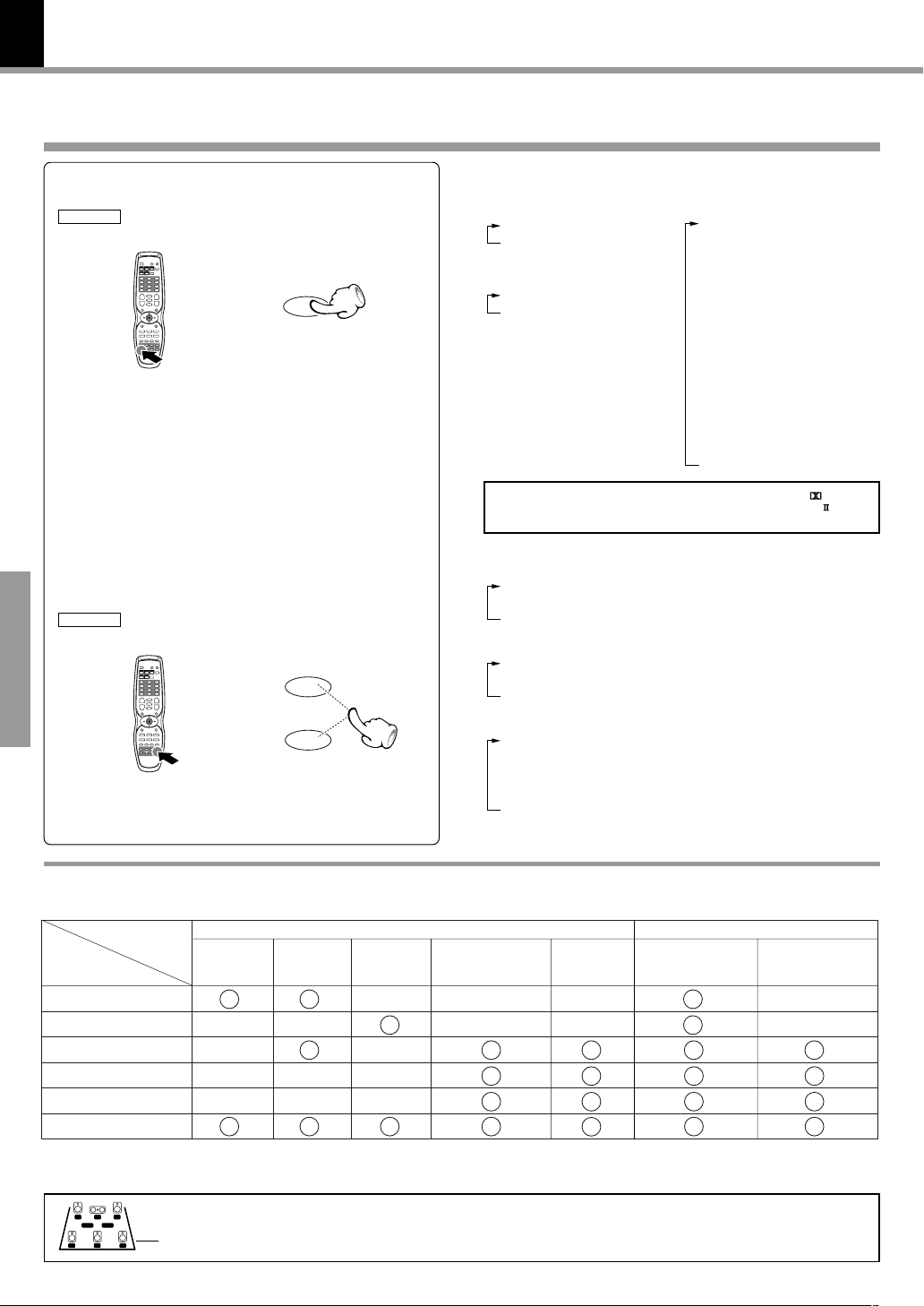
Selecting a LISTEN mode
DVR-8100 (EN)
Press the Listen mode key repeatedly
1
REMOTE
Press the TRIM (5/∞) keys to select the
2
mode while the display is scrolling
REMOTE
Operations
Listen mode
5
TRIM
∞
Each press switches the mode
(For DTS sources)
1 DTS
2 DTS STEREO
(For DOLBY DIGITAL sources)
1 DOLBY DIGITAL
2 STEREO
The indicator for the presently selected LISTEN
mode will light.
(For PCM sources)
1 Pro Logic II modes
÷ DOLBY PL II MOVIE
÷ DOLBY PL II MUSIC
÷ DOLBY PRO LOGIC
2 CS II modes
÷ CS II MUSIC
÷ CS II MONO
÷ CS II CINEMA
3 DSP modes
÷ ARENA
÷ JAZZ CLUB
÷ THEATER
÷ STADIUM
÷ DISCO
4 STEREO
÷ Pro Logic II modes
1 DOLBY PL II MOVIE
2 DOLBY PL II MUSIC
3 DOLBY PRO LOGIC
÷ CS II modes
1 CS II MUSIC
2 CS II MONO
3 CS II CINEMA
÷ DSP modes
1 ARENA
2 JAZZ CLUB
3 THEATER
4 STADIUM
5 DISCO
÷ STEREO
DIGITAL
CS DTS
DSP
Pro Logic
Listen modes available for each source
The following table shows which listen modes are available for each type of disc/source.
Sources
Listen modes
DOLBY DIGITAL
DTS
DOLBY PRO LOGIC II
CS II
DSP
STEREO
*1MPEG multichannel audio discs are downmixed to 2-channel stereo before output.
2
Selectable Listen modes for SAT/CABLE and VCR digital input differ according to the input source.
*
LC
LS RS
The IN/OUT indicators indicate input signals during playback of DOLBY DIGITAL or DTS sources and
R
LFESW
output signals at all other times.
S
DOLBY
DIGITAL
(5.1ch)
This bar will disappear when input signals of DOLBY DIGITAL or DTS sources are detected.
DOLBY
DIGITAL
(2ch)
Disc Type
DTS
*1MPEG MULTI-
CHANNEL AUDIO
VCD/CD
(PCM,
MP3)
INPUT
2
*
SAT/CABLE,
VCR
Digital COAX/OPTI
SAT/CABLE,
VCR
ANALOG
Page 19

Adjusting the sound
DVR-8100 (EN)
What are LISTEN modes?
You can experience true home-theater sound with your new system. This system incorporates several listen modes to let you
enjoy surround sound with a wide variety of program sources. Each produces multiple channels of surround-sound, but each
does it differently.
● Dolby Digital: Dolby Digital uses an encode/decode process based on its theatrical digital surround sound technology. The five
main channels are full-frequency and independent, so sound can completely envelop you or soar anywhere in the room, just
like at the movies.
Compared with Dolby Pro Logic, Dolby Digital has more clarity, greater surround envelopment, and more realistic sound
movement between channels.
● Dolby Pro Logic/Dolby Pro Logic II: Dolby Pro Logic reproduces a surround sound like in a movie theater from Dolby Surround-
encoded program source (videotape or LaserDisc software carrying the Dolby Surround logo), and features excellent sound
movement on the front and a surrounding atmosphere of movie theaters. Meanwhile, Dolby Pro Logic II decodes a signal
encoded in 2 channels into 5-channel signals composed of the left/right front signals, center signal and surround left/right signals.
Dolby Pro Logic II is an advanced version of the decoding technology used with Dolby Pro Logic. It inputs 2-channel signals from
a Dolby Surround-encoded source and reproduces 5-channel signals in which the surround channel is divided into independent
channels for the left and right. Dolby Pro Logic II has the MOVIE mode and MUSIC mode, and the MUSIC mode enables
independent adjustment of three parameters including Panorama mode, Dimension and Center Width.
● DTS : DTS has five full-frequency channels that create effects nearly identical to those in a theater. Sounds seem to zoom from
one place to another or entirely surround you. Like Dolby Digital, DTS has much-improved clarity, surround and sound movement
capability compared with Dolby Pro Logic. This listen mode is available on CD, LD, and DVD media. DTS is a strictly digital format
that can be supplied only by a CD, LD, or DVD player that supports DTS sound.
● DSP (Digital Signal Processing): DSP allows you to create your own custom surround sound environments and use them with
any source (except Dolby Digital and DTS). You can select the ambience of an ARENA, JAZZ CLUB, THEATER, STADIUM or
DISCO to your taste.
● SRS CS II (Circle Surround II): Circle Surround II™ improves on its predecessor Circle Surround (CS-5.1) by enabling you to
experience powerful multi-channel surround sound playback from mono, stereo or Dolby Surround encoded audio and video
sources. You already enjoy listening to Dolby Digital and DTS multi-channel sound through your multiple speakers. Now, with
CS II you can also listen to audio CDs, MDs, television and radio broadcasts in full surround sound. You will discover a new type
of sound experience through SRS Circle Surround II.
The CS system dramatically reduces storage space requirements for multi-channel content. It creates a listening environment
that places the listener “inside” music performances, and dramatically improves both hi-fi audio and conventional surround
encoded video material. In addition, the CS II decoder includes patented SRS Dialog Clarity Enhancement ™ and TruBass ™
technologies. When translated over home theater, dialog mixed for the cinema may become difficult to understand and SRS
Dialog Clarity solves this problem by improving dialog clarity, even when playing back Dolby Digital or DTS sources. TruBass
creates rich, deep bass in small speaker systems without the need for a subwooder.
● Stereo: Stereo listen mode provides standard stereo sound to the front left and right speakers.
19
Operations
“Circle Surround II” and
license from SRS Labs, Inc.
®
symbol are trademarks of SRS Labs, Inc. “Circle Surround II” technology is incorporated under
DTS disclaimer clause
DTS Digital Surround™ is a discrete 5.1 channel digital audio format available on CD, LD, and DVD software which consequently cannot be
decoded and played back inside most CD, LD, or DVD players. For this reason, when DTS-encoded software is played back through the
analog outputs of the CD, LD, or DVD player, excessive noise will be exhibited. To avoid possible damage to the audio system, proper
precautions should be taken by the consumer if the analog outputs are connected directly to an amplification system. To enjoy DTS Digital
Surround™ playback, an external 5.1 channel DTS Digital Surround™ decoder system must be connected to the digital output (S/P DIF,
AES/EBU, or TosLink) of the CD, LD or DVD player.
This unit is equipped with DTS Digital Surround™ decoder.
Page 20

20
Adjusting the sound
DVR-8100 (EN)
ACTIVE EQ.
You can enjoy more impressive sound effect when ACTIVE EQ is turned on during Dolby Digital and DTS playback
and, when in PCM and analog stereo mode. This function provides the best equalization for your speakers.
Press the ACTIVE EQ key repeatedly
MAIN UNIT
ACTIVE EQ
REMOTE
Active EQ./
SOUND
5
TRIM
∞
Each press switches the ACTIVE EQ.
1 CINEMA: effective when watching a movie
(ACTIVE EQ. indicator lit)
2 MUSIC: effective when listening to music
(ACTIVE EQ. indicator lit)
3 TV: effective when watching TV
(ACTIVE EQ. indicator lit)
4 OFF
÷ When operating the remote, press the Active EQ. key
repeatedly until the unit enters one of the ACTIVE EQ
modes above. Then press TRIM keys to select the desired
ACTIVE EQ mode.
NIGHT mode (Dolby Digital sources only)
Anytime you don’t want to experience the loud and soft volume extremes of recorded sound (for example, late at
night), use NIGHT function to reduce volume extremes.
Press the SOUND key repeatedly
1
REMOTE
Operations
Press the TRIM (5/∞) key
2
REMOTE
Active EQ./
SOUND
5
TRIM
∞
Displayed NIGHT OF(off) (or NIGHT ON).
DVD AUDIO
DVD VIDEO
AUTO DETECT
ACTIVE EQ
SOUND EQ
DIGITAL
Each press switches the mode
1 NIGHT OF (off)
2 NIGHT ON
÷ Adjust while the display is lit.
L C
LS RS
R
LFESW
S
BASS and TREBLE Adjustments
Press the SOUND key repeatedly
1
REMOTE
Active EQ./
SOUND
Press TRIM (5/∞) to adjust the level
2
REMOTE
To increase
5
TRIM
∞
To decrease
Select BASS (bass) or TRBL (treble).
DVD AUDIO
DVD VIDEO
AUTO DETECT
ACTIVE EQ
SOUND EQ
DIGITAL
L C
LFESW
S
LS RS
R
÷ The bass level can be adjusted between +10 and -10.
÷ The treble level can be adjusted between +10 and -10.
÷ Adjust while the display is lit.
÷ Front left and right speakers only.
Page 21

Adjusting the Pro Logic II MUSIC mode
Adjusting the sound
DVR-8100 (EN)
21
Press the Listen mode key repeatedly
1
and select Pro Logic ll mode
REMOTE
Listen mode
Press TRIM (5/∞) to select DOLBY PL ll
2
MUSIC.
REMOTE
Press the SOUND key repeatedly
3
REMOTE
Press TRIM (5/∞) to adjust the level
4
REMOTE
5
TRIM
∞
Active EQ./
SOUND
5
TRIM
∞
Select a Pro Logic II mode.
1 Pro Logic II modes
2 CS II modes
3 DSP modes
4 STEREO
DVD AUDIO
DVD VIDEO
AUTO DETECT
ACTIVE EQ
SOUND EQ
Pro Logic
L C
LFESW
S
LS RS
R
Operation is only possible in Pro Logic II MUSIC mode.
Select PANOR (panorama), DIMEN (dimension), or C WIDTH
(center width).
DVD AUDIO
DVD VIDEO
AUTO DETECT
ACTIVE EQ
SOUND EQ
Pro Logic
L C
LFESW
S
LS RS
R
÷ Panorama: Expands the image of front-channel stereo to the
surround speakers to create a sound environment that fills your
surroundings. Select: ON/OF (off)
÷ Dimension: This controls the balance between the Front and
Rear in 2 steps on the front and 2 steps on the rear. Set this
parameter to one of the Front steps if the surround effect is too
strong, or to one of the Back steps if it is too weak. Select: F-2,
F-3, R-2, R-3
÷ Center Width: The center channel signal can be divided and
distributed to the Front L/R channels. Use this adjustment when
the center image seems to be too strong. Select: 0~7
Operations
Input Attenuator
Use these adjustments if the CLIP indicator lights during playback of an external source. The input attenuator settings are stored
separately for each source. (for Analog sources only)
Select Pro Logic II, CS II, DSP or STEREO mode.
1 Pro Logic II modes
Press the Listen mode key repeatedly
1
REMOTE
Listen mode
Press the SOUND key repeatedly
2
REMOTE
Active EQ./
SOUND
Press TRIM (5/∞) to adjust the level
3
REMOTE
5
TRIM
∞
2 CS II modes
3 DSP modes
4 STEREO
DVD AUDIO
DVD VIDEO
AUTO DETECT
ACTIVE EQ
SOUND EQ
Pro Logic
L C
LFESW
S
LS RS
R
Operation is not possible with DOLBY DIGITAL and DTS
source.
Select I.ATT.
DVD AUDIO
DVD VIDEO
AUTO DETECT
ACTIVE EQ
SOUND EQ
Pro Logic
L C
LFESW
S
LS RS
R
Each press switches the I.ATT level
1 I.ATT 0
2 I.ATT –6
3 I.ATT –12
÷ Adjust while the display is lit.
Page 22

22
Display
Changing the display
DVR-8100 (EN)
Press the DISPLAY key.
REMOTE
DISPLAY
Each press switches the display.
When playing a CD
When playing a DVD
1 Track/chapter
2 Time
When playing a MP3 disc
1 Track
2 Title
3 Time
(VCD)
1 Track
2 Time
Dimmer
The brightness of the display can be changed in 3 levels. Adjust the brightness as you like by pressing the DISPLAY key.
Press the DISPLAY key for more than
2 seconds
REMOTE
Operations
Each press switches the Dimmer level
1 DIMMER OFF
2 DIMMER 1
3 DIMMER 2
DISPLAY
Page 23

Receiving broadcast station
It is also possible to receive them by one-touch operations
by storing up to 30 stations in the preset memory. (¢)
TUNER/
BAND
AUTO/
MONO
1, ¡
4, ¢
4, ¢
23
DVR-8100 (EN)
INPUT
Select the TUNER input
1
INPUT
Select the broadcast band
2
REMOTE
TUNER
BAND
Select a tuning mode
3
REMOTE
AUTO/MONO
7
REMOTEMAIN UNIT
TUNER
BAND
When using the main unit, press INPUT repeatedly to select
the tuner. When the BAND key on the remote is pressed, this
unit will be switched on automatically.
Auto tuning mode indicator
DVD AUDIO
DVD VIDEO
AUTO DETECT
ACTIVE EQ
SOUND EQ
Band display
Preset number
Stereo tuning indicator
AUTO ST.
TUNED CLIP
MHz
Frequency display
LC
LFESW
S
LS RS
Tuning indicator
R
Each press changes the band.
1 FM
2 AM
Each press switches the mode
1 auto tuning mode
AUTO
Lit
2 manual tuning mode
When the TUNE keys are pressed in AUTO mode, a station will be
tuned in automatically and tuning will stop. Stereo reception will be
made automatically when a stereo broadcast with sufficient signal
strength is received.
Operations
Select a station
4
P.CALL (preset call) AUTO (auto tuning) MANUAL (manual tuning)
REMOTEMAIN UNIT REMOTE
SKIP
¢4
P.CALL
¢34
Press the 4 , ¢ keys to select a
preset station.
TUNE/TV VOL.
¡1
Press the TUNE key to receive the next
tuned station automatically
REMOTE
TUNE/TV VOL.
¡1
Each time a key is pressed, the frequency
is changed by one step.
When a key is pressed continuously, the
frequency changes continuously.
Use the manual tuning mode when reception is noisy due to weak reception. (In the
manual mode, stereo broadcasts are received in monaural.)
Page 24

24
Receiving broadcast station
You can store up to 30 stations in the memory and recall with
a single touch of the key.
4, ¢
PRESET
Storing the broadcast stations (one-by-one presetting)
Select a station (auto tuning or manual
1
tuning)
Press the PRESET key
2
REMOTE
Operations
Select the desired preset number
3
REMOTE
£
PRESET
8
P.CALL
¢34
Presetting can be done with mixing of FM and AM stations.
(Example)
01: FM 90.00
02: AM 810
03: FM 88.00
Blinks
DVD AUDIO
DVD VIDEO
AUTO DETECT
ACTIVE EQ
SOUND EQ
PGM
Please perform the next operation while the indicator is
blinking.
In case of input with the
number keys, a preset number will be decided simply
by input of a 2-digit number
without pressing the ENTER
DVD AUDIO
DVD VIDEO
AUTO DETECT
ACTIVE EQ
SOUND EQ
key.
AUTO ST.
TUNED CLIP
PGM
DVR-8100 (EN)
MHz
Press the PRESET key
4
REMOTE
PRESET
8
Repeat steps 1 to 4 to preset other stations.
PGM
DVD AUDIO
DVD VIDEO
AUTO DETECT
ACTIVE EQ
SOUND EQ
CLEAR
321
654
987
+100+100
AUTO ST.
TUNED CLIP
MHz
Page 25

RDS is a system which transmits useful information (digital
TUNER/
BAND
1, ¡
RDS
4, ¢
data) for FM broadcasts together with the broadcast signal.
Tuners and receivers designed for RDS reception can extract
the information from the broadcast signal for use with
various functions such as automatic display of the station
name.
Using RDS function ( for U.K. and Europe only)
Functions made possible with RDS
Receiving broadcast station
DVR-8100 (EN)
25
PS (Program Service Name) Display :
When an RDS broadcast is received, the station name is automatically displayed.
PTY (Program Type Identification) Search :
The tuner automatically searches for a station which is currently
broadcasting a specified program type (genre).
Using the RDS Display function
Select the FM broadcast station
1
£
TUNE/TV VOL.
¡1
or
Press the RDS key
2
ON SCREEN
Each press switches the display mode as follows.
1 PS NAME display
2 PTY display
3 CT display
4 RT display
5 Current FM frequency display
P.CALL
¢34
RDS
CT (Clock Time) :
Decodes the real time clock from the FM frequency.
RT (Radio text) :
Displays the radio text data transmitted by some RDS stations
when you select the RT mode.
AUTO ST.
TUNED CLIP
LC
DVD AUDIO
DVD VIDEO
AUTO DETECT
ACTIVE EQ
SOUND EQ
MHz
LFESW
S
LS RS
R
PS NAME
÷ If the PS information is being received, the PS name (BBC,
AFO, NDR, etc.) is shown on the display.
÷ If the PS information is not received, the original FM fre-
quency is shown.
÷ Even though no RDS key is pressed, the reception of PS
information ensues the PS name is displayed.
CT display
÷ If the CT information will take up to 2 minutes to be decoded
therefore the clock is not displayed immediately.
÷ If the CT information is not received, the “NO TIME” is
shown on the display.
÷ The CT clock does not update the system clock.
RT display
÷ Text data accompanying the RDS broadcast scrolls across
the display (64 characters can be displayed).
Operations
AUTO ST.
TUNED CLIP
LC
DVD AUDIO
DVD VIDEO
AUTO DETECT
ACTIVE EQ
SOUND EQ
RDS
LFESW
S
LS RS
R
←Scrolled display
÷ If the RT information is not received, the “NO TEXT” is
shown on the display.
Page 26

26
PTY function (for U.K. and Europe only)
Receiving broadcast station
DVR-8100 (EN)
The PTY information is composed of an identification symbol, which helps the FM radio to recognize the program type
of each FM station.
The 29 PTY modes are shown in the display by pressing
the PTY key.
Using the PTY search function
Select the FM band
1
£
TUNER
BAND
Press the PTY key
2
MENU/PTY
÷ The PTY MODE (POP M, ROCK M etc.) ap-
pears on the display.
Press the PTY key repeatedly to select
3
the desired program type.
Operations
When the program type is selected,
4
press
After display of NO PTY, return is made to the
normal display.
1
Auto-search the station sequentially
÷ Press PTY key during search to cancel.
PTY found
Lit
PTY not found
MENU/PTY
or ¡key.
Blink
PS display
DVD AUDIO
DVD VIDEO
AUTO DETECT
ACTIVE EQ
RDS
SOUND EQ
AUTO ST.
TUNED CLIP
LS
TUNER/
BAND
PTY
1, ¡
RDS Program types
Program Type Name
News NEWS
Current Affairs AFFAIRS
Information INFO
Sport SPORT
Education EDUCATE
Drama DRAMA
Culture CULTURE
Science SCIENCE
Varied VARIED
Pop Music POP M
Rock Music ROCK M
Easy Listening Music EASY M
Light Classical Music LIGHT M
Serious Classical Music CLASSICS
Other Music OTHER M
Weather WEATHER
Finance FINANCE
Children’s programs CHILDREN
Social affairs SOCIAL
Religion RELIGION
Phone in PHONE IN
Travel TRAVEL
Leisure LEISURE
Jazz Music JAZZ
Country Music COUNTRY
National Music NATION M
Oldies Music OLDIES
Folk Music FOLK M
Documentary DOCUMENT
Receiver Display
Page 27

Playback of disc
27
DVR-8100 (EN)
Basic play
Load a disc
1
MAIN UNIT
0
Select the DVD/CD
2
MAIN UNIT REMOTE
INPUT
÷ When a disc is set on the tray and DVD/CD is selected,
playback of the disc will be started automatically.
DVD/CD
DVD/CD
3
8
6
7
0
Label side
1 Open the tray.
2 Place a disc.
3 Close the tray.
÷ When the
pressed instead of the
66
6 (play/pause) key on the main unit is
66
00
0 (open/close) key in step 3, the
00
tray will close and playback will start automatically.
When a Disc Menu appears on the screen
In case of interactive DVDs, a Disc Menu appears on the screen.
Then press ENTER to select specific menu you want to play by using
Cursor keys.
When a menu screen is recorded on the disc, the
menu screen will be displayed when the TOP MENU
key is pressed. At the menu screen, the menu can be
selected by pressing the Cursor keys.
INPUT
Operations
Start playback
3
MAIN UNIT REMOTE
£
/
8
÷ Each press 6 key on the
main unit pauses and plays
the disc alternately.
÷ Press 8 key on the remote
To stop playback
MAIN UNIT
7
3
control unit to pause the disc.
PRESET
8
REMOTE
AUTO/MONO
7
÷ When the 6 key on the main unit is pressed while an
input other than disc is selected, the unit will be switched
to DVD/CD and playback will start.
AUTO ST.
DVD AUDIO
DVD VIDEO
AUTO DETECT
TITLE
ACTIVE EQ
CHAP
TRACK
SOUND EQ
CHAPTER No. (DVD), TITLE No. (DVD), TRACK No. (CD),
Time display, etc.
TUNED CLIP
LC
LFESW
S
LS RS
R
RESUME playback
When the 7 key has been pressed once during
playback to stop the playback, and then playback is
started again, play will start from the point where
the playback had been stopped. This is called the
RESUME function. When the 7 key is pressed again
during stop, the RESUME function is cancelled.
RESUME is cancelled when 5 minutes have passed in
RESUME status.
Page 28

28
Disc playback features
Notes
Notes
÷ You won’t hear the sound (audio) on the DVD
when you’re using the Skip, Search, Step or Slow
motion features.
÷ Playback features are not available during the
opening credits of a movie.
CD
DVD
To skip
backward
÷ The chapter (or track) in the direction of the key
÷ When the 4 key is pressed once during playback,
VCD
Skipping chapters or tracks
MAIN UNIT
To skip
forward
SKIP
¢4
REMOTE
To skip
backward
P.CALL
pressed is skipped, and the selected chapter (or track)
will be played from the beginning.
the chapter (or track) being played will be played from
the beginning.
To skip
forward
¢34
Playback of disc
Numeric
keys
VCD
Searching
To search
backward
4, ¢
STEP
TUNE/TV VOL.
¡1
To search
forward
11
1 or
11
4, ¢
¡¡
¡ key
¡¡
1 × 2 (F.SEARCH 1)/(R.SEARCH 1)
2 × 4 (F.SEARCH 2)/(R.SEARCH 2)
3 × 8 (F.SEARCH 3)/(R.SEARCH 3)
4 × 16 (F.SEARCH 4)/(R.SEARCH 4)
*
At the time of DVD playback only
*
SLOW
1, ¡
CD
DVD
REMOTE
÷ During playback, press the
÷ Each press switches the searching speed.
÷ Press the 3(PLAY) key at any time to resume normal
playback.
÷ Audio is not output during F.SEARCH or R.SEARCH
playback.
DVR-8100 (EN)
CD
Playback from desired track
Operations
REMOTE
DVD
VCD
REMOTE
DVD
VCD
REMOTE
321
654
987
PGM
CLEAR
+100+100
STEP (freeze frame and frame advance)
TUNE/TV VOL.
STEP
¡1
Slow motion playback
SLOW
TUNE/TV VOL.
¡1
÷ Select the desired track No.
÷ Press the numeric keys as shown below
(Example)
To select track No. 23 : 23
÷ When a number exceeding the largest track No. on the
CD being played is specified, a question mark "Tr ?" will
be displayed.
÷ Each time you press the 1, ¡ keys, the picture
advances one frame.
÷ At the time of VCD playback, backward STEP is not
possible.
÷ Press the 3(PLAY) key to resume normal playback.
÷ During playback, press the SLOW key, then press the
1, ¡ keys.
÷ Each press 1, ¡ keys switches the motion speed.
(At the time of DVD playback)
1 F.SLOW 1/16 (R.SLOW 1/16)
2 F.SLOW 1/8 (R.SLOW 1/8)
3 F.SLOW 1/4 (R.SLOW 1/4)
4 F.SLOW 1/2 (R.SLOW 1/2)
(At the time of VCD playback)
1 F.SLOW 1/8 (R.SLOW is not possible)
2 F.SLOW 1/4 (R.SLOW is not possible)
3 F.SLOW 1/2 (R.SLOW is not possible)
÷ Press the 3(PLAY) key to resume normal playback.
Page 29

Using the On-screen banner display
Notes
Notes
MULTI CONTROL
/
÷
ENTER
23
5
∞
DVR-8100 (EN)
The on-screen Banner Display contains many playback features. To see the Banner Display, press the ON SCREEN
key while a disc is playing. Use the Cursor (Up/Down/Left/Right) keys to move through the different features in the
Banner Display. Each feature is illustrated with an icon.
1 During playback, press the ON SCREEN key.
When playing a DVD
29
MAIN UNIT
ON SCREEN
REMOTE
ON SCREEN
2 Press the Cursor left/right (2/3) keys to high-
light a banner display icon.
MAIN UNIT
5
23
MULTI CONTROL
∞
/
÷
ENTER
REMOTE
ENTER
3 Press the ENTER key.
MAIN UNIT
REMOTE
ENTER
CHAPTER SUBTITLES BOOKMARKS
TITLE AUDIO ANGLES DISC TYPE
TIME INDICATOR
When playing a CD/VCD
INTROSCAN TIME INFORMATION
TRACK BOOKMARKS DISC TYPE
TIME INDICATOR
Switch the CD time indicator as follows.
1 Select the time information with the cursor key.
2 Each time the ENTER key is pressed, the time
indicator changes as follows.
1 Track Elapsed
2 Track Remain (remaining time of the track being played)
3 Disc Elapsed (elapsed time of the disc being played)
4 Disc Remain (remaining time of the disc being played)
(elapsed time of the track being played)
Operations
To display disappear from the screen
Press the ON SCREEN key.
MAIN UNIT
ON SCREEN
REMOTE
ON SCREEN
÷ You can only access the banner display when you’re
playing a disc.
÷ The banner display feature are only available if the disc was
created with that particular feature (i.e., if you select the
Subtitle icon, you won’t be able to change the subtitle
language unless the author of the disc created the disc with
subtitles).
÷ The invalid symbol
appears on the screen when you
press a key that doesn’t have any function. If one of the
icons is “grayed out,” the banner display feature isn’t
available for the disc you’re playing.
Page 30

30
Notes
Notes
MULTI CONTROL
/
÷
ENTER
23
5
∞
ON SCREEN
DVD
Selecting a Title
DVD
CD
Using the On-screen banner display
VCD
Selecting a Chapter or Track
DVR-8100 (EN)
Some discs contain more than one title. For example,
there might be four movies on one disc (each movie
might be considered a title).
1 During playback, press the ON SCREEN key.
MAIN UNIT
ON SCREEN
REMOTE
ON SCREEN
2 Press the Cursor left/right (2/3) keys until the
TITLE icon is highlighted.
MAIN UNIT
5
23
MULTI CONTROL
∞
/
÷
ENTER
REMOTE
ENTER
3 Press the ENTER key.
(“T__” appears)
MAIN UNIT
Operations
REMOTE
ENTER
Because DVD discs use digital technology, a title can
be divided into individual chapters (similar to tracks on
a CD). You can skip a specific chapter by using the
Chapter section in the Banner Display.
1 During playback, press the ON SCREEN key.
MAIN UNIT REMOTE
ON SCREEN
2 Press the Cursor left/right (2/3) keys until the
CHAPTER or TRACK icon is highlighted.
MAIN UNIT REMOTE
5
23
MULTI CONTROL
∞
÷
ENTER
/
ENTER
3 Press the ENTER key.
(“C__” or “Tr__” appears)
MAIN UNIT REMOTE
5
23
MULTI CONTROL
∞
÷
ENTER
/
ENTER
4 Use the numeric keys on the remote or the cursor
keys on the main unit to enter the title number.
MAIN UNIT
5
23
MULTI CONTROL
∞
/
÷
ENTER
REMOTE
PGM
When you enter a one-digit Title number, you may
have to press ENTER on the remote after pressing
the numeric key (1~9) on the remote. Otherwise
press 0 first and the other value. Then play starts.
This varies depending on number of Title within the
disc you’re playing.
Note
Note
Some discs only have one title.
CLEAR
4 Use the numeric keys on the remote, or the SKIP
keys on the main unit to enter the chapter or track.
MAIN UNIT REMOTE
321
654
987
+100+100
SKIP
CLEAR
+100+100
321
654
987
¢4
PGM
When you enter a one-digit chapter or track number,
you may have to press ENTER on the remote after
pressing the numeric key (1~9) on the remote. Otherwise press 0 first and the other value. Then play
starts. This varies depending on number of chapter
or track within the disc you’re playing.
÷ The Chapter feature won’t work if the disc isn’t
formatted with separate chapters.
÷ P.B.C. on mode of VCD, the Selecting a Track
function may not work.
Page 31

Using the On-screen banner display
Notes
Notes
ON SCREEN
DVR-8100 (EN)
31
DVD
Changing the Audio Language
If the disc was created with different language tracks,
you can use the Banner Display to temporarily change
the DVD player’s Audio setting.
Using the on-screen banner display
1 During playback, press the ON SCREEN key.
MAIN UNIT
ON SCREEN
2 Press the Cursor left/right (2/3 ) keys until the
AUDIO icon is highlighted.
MAIN UNIT
5
23
MULTI CONTROL
∞
÷
ENTER
/
3 Press the ENTER key.
MAIN UNIT
5
23
MULTI CONTROL
∞
÷
ENTER
/
REMOTE
ON SCREEN ON SCREEN
REMOTE
ENTER
REMOTE
ENTER
DVD
Changing the Subtitle Language
You can change the Subtitle language while you’re
watching a disc (but only if the disc was created with
subtitles).
Using the on-screen banner display
1 During playback, press the ON SCREEN key.
MAIN UNIT REMOTE
2 Press the Cursor left/right (2/3) keys until the
SUBTITLE icon is highlighted.
MAIN UNIT REMOTE
5
23
MULTI CONTROL
∞
÷
ENTER
/
3 Press the ENTER key.
MAIN UNIT REMOTE
5
23
MULTI CONTROL
∞
÷
ENTER
/
ENTER
ENTER
Operations
The audio menu appears
4 Press the ENTER key repeatedly to select the
audio language.
MAIN UNIT
5
23
MULTI CONTROL
∞
/
÷
ENTER
REMOTE
÷ The menu is switched off when no operation is
performed for about 5 seconds.
1. The language feature only works if the disc was created with
Notes
Notes
multiple audio tracks.
2. When you chose an audio language from the Banner Display,
you only override the audio language setting in the DVD Player’s
main menu (in the Language Preferences menu within Setup
menu) temporarily.
ENTER
Displayed when
SUBTITLE is ON
The subtitle menu appears
4 Select the subtitle language with press the EN-
TER key.
MAIN UNIT REMOTE
5
23
MULTI CONTROL
∞
÷
ENTER
/
ENTER
5 Press the S.TITLE key to turn subtitles ON or OFF.
Remote control unit only
S.TITLE
REC
¶
÷ The menu is switched off when no operation is
performed for about 5 seconds.
1. The subtitle feature only works if the disc was created with
multiple subtitle tracks.
2. The subtitle menu of the disc appears in some discs.
Page 32

32
Note
Note
MULTI CONTROL
/
÷
ENTER
23
5
∞
MULTI CONTROL
/
÷
ENTER
23
5
∞
Using the On-screen banner display
DVR-8100 (EN)
DVD
Changing the Camera angle
Some disc contains multiple angles in particular scene
or sequence. If the disc only has one angle, this feature
won’t work.
Using the on-screen banner display
1 During playback, press the ON SCREEN key.
MAIN UNIT
ON SCREEN ON SCREEN
2 Press the Cursor left/right (2/3) keys until the
ANGLE icon is highlighted.
MAIN UNIT
5
23
MULTI CONTROL
∞
÷
ENTER
/
3 Press the ENTER key.
MAIN UNIT
Operations
REMOTE MAIN UNIT REMOTE
ON SCREEN ON SCREEN
REMOTE
ENTER
REMOTE
ENTER
VCD
CD
Using IntroScan function
IntroScan plays the first few seconds of each track on
only one disc similar to the scan feature that’s on many
car radios.
Using the on-screen banner display
1 During playback, press the ON SCREEN key.
2 Press the Cursor left/right (2/3) keys until the
IntroScan icon is highlighted.
MAIN UNIT REMOTE
3 Press the ENTER key.
MAIN UNIT REMOTE
5
23
MULTI CONTROL
∞
/
5
23
MULTI CONTROL
∞
/
÷
÷
ENTER
ENTER
ENTER
ENTER
The ANGLE menu appears
4 Press the ENTER key repeatedly to select the
angle.
MAIN UNIT
REMOTE
ENTER
÷ The menu is switched off when no operation is
performed for about 5 seconds.
÷ The first 10 seconds of each track play.
÷ After Intro Scan goes through all of the tracks, it
stops.
÷ If you want to stop IntroScan while it’s in progress,
just press ENTER key on the remote (the current
track starts playing in its entirety).
(When the On-screen display has gone out, press the
ON SCREEN key, select Intro Scan, and press the ENTER key.)
P.B.C. on mode of VCD, the IntroScan function may not
work.
Page 33

Using the On-screen banner display
ON SCREEN
MULTI CONTROL
/
÷
ENTER
23
5
∞
MULTI CONTROL
/
÷
ENTER
23
5
∞
DVR-8100 (EN)
33
CD
VCD
Using Bookmarks
DVD
The bookmark feature lets you mark a point on the disc that you can go to quickly. You can store up to 9 bookmarks.
Create the bookmark Recalling a bookmarked scene
1 During playback, press the ON SCREEN key.
MAIN UNIT
ON SCREEN
REMOTE
ON SCREEN ON SCREEN
2 Press the Cursor left/right (2/3) keys until the
BOOKMARK icon is highlighted.
MAIN UNIT REMOTE
5
23
MULTI CONTROL
∞
/
÷
ENTER
ENTER
3 Press the ENTER key.
MAIN UNIT REMOTE
ENTER
Return to the previous banner display
The bookmark menu appears
1 During playback, press the ON SCREEN key.
MAIN UNIT REMOTE
2 Press the Cursor left/right (2/3) keys until the
BOOKMARK icon is highlighted.
MAIN UNIT REMOTE
5
23
MULTI CONTROL
∞
/
÷
ENTER
ENTER
3 Press the ENTER key.
MAIN UNIT REMOTE
5
23
MULTI CONTROL
∞
÷
ENTER
/
The bookmark appears
ENTER
Operations
4 Move cursor to the Mark row, and press ENTER
when you reach the point you want to mark.
MAIN UNIT
÷ You can also make a bookmark by pressing a numeric
key (1~9) when the cursor is in the Mark row.
÷ Press the ON SCREEN key to switch the menu off.
REMOTE
ENTER
Mark row
Clearing a bookmark
÷ The bookmark is cleared each time the disc changes or
when the power is turned off.
Notes
Notes
÷ If all 9 bookmarks are in use, you can still mark new
scenes, but the previous bookmarks will be erased.
÷ Depending on the disc, the Bookmark function may not
work
÷ P.B.C. on mode of VCD, the Bookmark function may not
work.
4 Move the cursor to the Go To row and select the
bookmark scene you want to activate.
MAIN UNIT
5
23
MULTI CONTROL
∞
÷
ENTER
/
÷ You can also go to a bookmark by pressing a numeric
key (1~9) when the cursor is in the Go To row .
REMOTE
ENTER
Go To row
5 Press the ENTER key to active the bookmark.
MAIN UNIT
5
23
MULTI CONTROL
∞
÷
ENTER
/
÷ Press the ON SCREEN key to switch the menu off.
REMOTE
ENTER
Page 34

34
Note
Note
Using the On-screen banner display
DVR-8100 (EN)
CD
VCD
Repeat play
DVD
Desired titles or discs can be played back repeatedly.
÷ Repeat Disc – Repeat the disc that is playing.
÷ Repeat Title – Repeat the title that is playing.
÷ Repeat Chapter – Repeat the chapter that is playing.
÷ Repeat Track – Repeat the track that is playing.
During playback, press REPEAT key
on the remote repeatedly.
+
REPEAT
The Repeat display appears
DVD AUDIO
DVD VIDEO
ACTIVE EQ
SOUND EQ
Display
Lit
Each press switches the REPEAT
mode.
Operations
+
REPEAT
CD
VCD
A-B Repeat play
DVD
The A-B repeat function lets you mark a segment to
repeat between the beginning “A” and the end “B” of
the segment you want to replay.
1 Press the A-B key on the remote
when you want to choose a scene
(sound) as the beginning point.
A-B
–
The Repeat A- display appears
DVD AUDIO
A-
Display
Lit
2 Press the A-B key again to choose a
scene (sound) as the end point.
A-B
–
At the time of DVD playback
1 Repeat Disc
2 Repeat Title
3 Repeat Chapter
4 Repeat Off
At the time of CD/VCD playback
1 Repeat Disc
2 Repeat Track
3 Repeat Off
÷ To cancel repeat playback, press the REPEAT key and
select "Repeat off".
÷ The menu is switched off when no operation is per-
formed for about 5 seconds.
Note
Note
÷ P.B.C. on mode of VCD, the Repeat play function may not
work.
The Repeat A-B display appears
DVD AUDIO
A-B
Display
÷ To cancel A-B Repeat playback, press the A-B key and
select "Repeat off".
÷ The menu is switched off when no operation is per-
formed for about 5 seconds.
P.B.C. on mode of VCD, the A-B Repeat play function may
not work.
Lit
Page 35

VCD
CD
Random play
The tracks of disc are played in random order.
Using the On-screen banner display
DVR-8100 (EN)
35
During playback or stop mode, press
RANDOM key on the remote.
INPUT MODE
RANDOM
Display
DVD AUDIO
DVD VIDEO
The Random Play display appears
Lit
RDM
Each time you press RANDOM key on
the remote, random play would be on
and off.
1 “Random Play”
2 “Standard Play”
The Standard Play display appears when
random is off.
÷ When the RANDOM key is pressed during playback, the tracks
of the disc being played will be selected in random order for
playback.
÷ After all tracks of a disc have been played in random order,
playback will stop. (Random mode will be cancelled.)
Operations
÷ The menu is switched off when no operation is
performed for about 5 seconds.
Notes
Notes
÷ When playing a DVD, the Random function may not
work.
÷ P.B.C. on mode of VCD, the Random play function
may not work.
Page 36

36
DVD
CD
VCD
Program play
You can listen to the desired tracks or chapters of the current disc in any desired order.
Registering and playing the program
Insert the disc to be used in programming in the tray, close it and press the 3(PLAY) key so that the player reads
the disc information by playing disc until display “READING” disappears. (If the tray is opened after this, the above
procedure should be repeated so that the player reads disc information again.)
Program Edit
1 During stop mode, press the PGM
key on the remote.
PGM
+100
2 Select a specific title/chapter or
track by pressing Cursor up/down
(5/∞) keys or numeric keys (0-9).
Program edit display appears.
PROGRAM EDIT
Title
Chapter
2
(12) (2)
All
Add
Delete
Play
Done
DVR-8100 (EN)
Playlist
CT
Operations
ENTER
3 Press the ENTER key.
ENTER
4 Select Add icon on the screen to
register selected value onto
Playlist, then press the ENTER key.
ENTER
ENTER
5 You can select maximum 32 val-
ues by repeating step 2 - 4.
(An example of DVD program edit menu)
: Selected icon
2
: An icon which can be selected
: An icon which presently can not be selected
PROGRAM EDIT
Title
Chapter
All
2
(12) (2)
Add
Delete
Play
Done
Playlist
CT
2 All
÷ When you don’t add values onto “Playlist” and
return to play mode, select Done icon and press
ENTER key on the remote.
÷ While a disc is playing, press PGM key on the remote
to start Program play
÷ To return to standard play, press the PGM key again.
÷ MP3 discs can not be programmed with this pro-
gram mode. (MP3 program play r)
6 Press the 3(PLAY) key to start play-
back.
Note
Note
Add / Insert icon --- Add / Insert value to “Playlist”
Delete icon --- Delete value from “Playlist”
Play icon --- Play program play
Done icon --- Return to stop or resume mode
Page 37

Insert chapter or track
During stop mode, press the PGM key on the remote
1 Select a specific title/chapter or
track to insert by pressing Cursor
up/down (5/∞) keys or numeric
keys (0-9).
ENTER
2 Move the cursor with the Cursor
right (‰) key to the "Playlist" and
select the column to be added with
the Cursor up/down (5/∞) keys.
ENTER
PROGRAM EDIT
Title
Chapter
All
2
(12) (2)
Insert
Delete
Play
Done
Program play
DVR-8100 (EN)
Playlist
CT
2 All
3 12
1 8
1 All
3 5
37
(The color of the column where the
Cursor is located will change.)
3 Move the cursor with the Cursor
left (2) key to the Insert icon and
press the ENTER key.
ENTER
ENTER
The new chapter or track will be inserted before (above) the selected
column.
Delete Program
During stop mode, press the PGM key on the remote
1 Use the Cursor up/down (5/∞) keys
to select the column to be deleted
from the "Playlist". (The color of the
column where the Cursor is located
will change.)
ENTER
2 Press the Cursor left (2) key, use
the Cursor up/down keys to move
the Cursor to the Delete icon, and
press the ENTER key.
Or press the CLEAR key.
ENTER
Selected value deletes
ENTER
(An example of DVD program edit menu)
PROGRAM EDIT
Title
Chapter
All
2
(12) (2)
PROGRAM EDIT
Title
Chapter
All
2
(12) (2)
Insert
Delete
Play
Done
Add
Delete
Play
Done
Playlist
CT
2 All
3 12
1 8
2 All
1 All
3 5
Playlist
CT
2 All
3 12
1 8
1 All
3 5
Release Program play
In following case, Program play would be released.
1. When you open and close tray.
2. When you turn power off and on.
Operations
Note
Note
P.B.C. on mode of VCD, the Program play
function may not work.
Page 38

38
Menu playback
DVR-8100 (EN)
VCD
Hierarchical structure of VCD menus
When an item is selected on the menu screen during playback of a P.B.C.-compatible VCD, another menu with more
details items may be displayed. When a number of menus are connected in multiple layers in this way, it is said that
the menus have a hierarchical structure. In this structure, the desired scene can be reached by repeating item
selections on the menu screens.
Example for a hierarchical structure
First level (menu)
Second level (submenu)
Third level (scenes)
Advancing
When an item is selected on the menu screen with the 3 key
or the numeric keys, advance is made to the next lower
menu level. When the advance destination is the “scene” to
Operations
be played, the contents will be played.
÷ When several menus (scenes) can be selected in each level,
screen switching is possible with the keys ¢ (NEXT) and 4
(PREV.).
Returning
Each time the RETURN key is pressed, return is made to the
next higher menu.
Examples of operation keys and indications used during VCD playback
Soft jacket indication
KENWOOD operation key
÷ Depending on the software, the jacket indication may differ from the above.
3
RETURN
4
¢
¢4
ENTER or SELECT
ENTER
Page 39

Menu playback
DVR-8100 (EN)
39
VCD
Playback without using the menu playback function
a P.B.C.-compatible VCD) (To P.B.C. On or Off)
Press the P.B.C. key on the remote control unit.
TOP MENU/P.B.C.
÷ For the track numbers, refer to the disc jacket or other
material.
÷ P.B.C. off mode : Without using menu playback function.
P.B.C. off mode
Goes off
DVD AUDIO
DVD VIDEO
ACTIVE EQ
P.B.C.
SOUND EQ
To return to menu playback
Press the P.B.C. key again.
P.B.C. on mode
Lit
DVD AUDIO
DVD VIDEO
ACTIVE EQ
P.B.C.
SOUND EQ
(In case of
Operations
To return to the previous screen
Press RETURN key on the remote control unit.
RETURN
÷ The VCD returns to the previous scene.
Page 40

40
MP3 function
DVR-8100 (EN)
Guidance of MP3
Media that can be played back with this equipment
Usable media : CD-ROM, CD-R, CD-RW
Usable format : ISO9660 level 1.
Files that can be played back : MP3 files
Creating media for playing back on this equipment
Compressing MP3
Please set up the transfer bit rate setting for the compression software when compressing MP3 files as follow.
MP3 Files : 128kbps recommended (32kbps-320kbps)
÷ This unit is compatible with 32 kHz, 44.1 kHz (recommended) and 48 kHz sampling frequencies.
Naming folders and files
Single-byte characters between A and Z, single-byte numerals between 0 and 9, and the single-byte underscore(_) can be
displayed. Ensure that the “.MP3”(MP3 files) extension log is attached to all file names.
÷ Never add the MP3 extension log to any files other than MP3 files. If the MP3 extension log is added to any files
other than MP3 files, the equipment will assume that they can be played back, and this will produce loud noises
in the speakers, resulting in damage of adverse effects.
Confirming media and files
Check to ascertain that MP3 files can be played back correctly on the personal computer in use prior to saving them onto the media.
Check to ensure that the saved file can be played back normally.
÷ It is not possible to confirm that files can be played back correctly while they are being saved onto the media.
When saving files onto media
Ensure that the session is closed or finalized when data has been written on media. There are cases where media on which the
session has not be closed or finalized will not be played back correctly with this equipment.
÷ There are cases were the folder names and file names will not be displayed correctly depending on the software
used to save them.
÷ Do not store files or folders other than MP3 on media to be played back with this equipment.
Operations
÷ It is recommended that ten or less sessions are stored when recording MP3 files onto a media.
÷ Some time may be required until the playback of multi-session discs starts.
÷ There are cases where playback is not possible when MP3 files (CD-ROM) and music CD information (CD-DA) are
saved on the same media.
Example for a hierarchical structure
ROOT
Folder
File
ROOT
Folder
File
Layer 1 Layer 2 Layer 3 Layer 4 Layer 1 Layer 2 Layer 3
Page 41

Playing back MP3
Note
Note
MP3 function
DVR-8100 (EN)
41
÷ It is not possible to play back folders and files (up to
223) that exceed the maximum limitations of the
media.
÷ A certain amount of time is required for the player
to confirm the media on which MP3 files have been
recorded before playback will commence.
÷ The files will be played back in the sequence in
which they were recorded (written).
÷ For the basic operation, refer to “Playback of disc”.
(¶)
However, searching function is not available with
MP3 discs.
Selecting a folder
When a MP3 disc is loaded in the main unit, you will
see a list of files of the first folder on the TV screen,
and the playback starts automatically.
If you want to select a different folder, follow the
procedure shown below.
1 During playback, press the RETURN key.
REMOTE
RETURN
MP3 On-screen display
Playing file name
Play mode
Standard Play
MY SONG1
HALLOW-1
MEGADETH
MADONNA
RCY23MNN
EXTREME
CARMAN-1
ITALY
EGALES
Folder icon
Root icon
Playing file No.
LIKE-1
Time elapsed
M3P
0:05:341
ALL CLEAR
Operations
ALL CLEAR icon
Standard Play
You will see the
return folder icon.
HALLOW-1
LIKE-1
2 Press the ENTER key on the Return folder icon.
You will see the list of folders.
REMOTE
ENTER
3 Use the Cursor up/down (5/∞) keys to select
the desired folder and press the ENTER key.
REMOTEMAIN UNIT
5
23
MULTI CONTROL
∞
÷
ENTER
/
23
5
∞
MULTI CONTROL
÷
ENTER
/
ENTER
ENTER
M3P
Program Play
HALLOW-1
LIKE-1
LUCKY-1
LET IT-1
YESTERDA
TRUE-1
OPEN-1
WHIHE-1
LIKE-1
1
LIKE-1
LUCKY-1
LIKE-3
INTORO-1
YESTERDA
WHIHE-1
HOLIDAY
OPEN-1
ALL CLEAR
Files
Return folder icon
Program window
Folder names and file names are displayed up to 8
characters. When folder names and file names are
recorded with more than 8 characters, the names will
be displayed in abbreviated form.
Page 42

42
MULTI CONTROL
/
÷
ENTER
23
5
∞
Selecting MP3 files
1 Select the desired folder and press the
ENTER key. q
2 Press Cursor up/down (5/∞) keys to select the
file, then press the ENTER key.
REMOTEMAIN UNIT
5
23
MULTI CONTROL
∞
÷
ENTER
/
÷ Playback will start from selected file.
23
5
∞
MULTI CONTROL
÷
ENTER
/
ENTER
ENTER
MP3 function
DVR-8100 (EN)
÷ The files and folders in the selected folder appear.
LIKE-1
Standard Play 1 0:05:34
HALLOW-1
LIKE-1
LUCKY-1
LET IT-1
YESTERDA
TRUE-1
OPEN-1
WHIHE-1
Press ENTER key on RETURN folder icon
to move to the upper layer.
LIKE-1
Standard Play 1
LIKE-1
LUCKY-1
LET IT-1
YESTERDA
TRUE-1
OPEN-1
WHIHE-1
WHIHE-2
NEVER-2
M3P
ALL CLEAR
M3P
0:05:34
ALL CLEAR
Selects the files to be played back directly
1 Select the desired folder and press the
ENTER key. q
Operations
2 Press Cursor left/right (2/3) keys to invert the
file numbers.
REMOTEMAIN UNIT
ENTER
3 Press the numeric keys on the remote to enter
the desired file number.
REMOTE
PGM
÷ If “– – –” is displayed after completion of the
file number entry, press the ENTER key before
“– ––” disappears.
÷ Playback will start from selected file.
CLEAR
+100+100
321
654
987
File No.
LIKE-1
Standard Play 1
LIKE-1
LUCKY-1
LET IT-1
YESTERDA
TRUE-1
OPEN-1
WHIHE-1
WHIHE-2
NEVER-2
WHIHE-1
Standard Play 7 0:00:01
WHIHE-1
WHIHE-2
NEVER-2
0:05:34
ALL CLEAR
ALL CLEAR
M3P
M3P
To select a different folder
Press Cursor left (2) key to move the cursor into the
left list. Then press the RETURN key twice to move
to the upper level folder, and select the desired
folder.
Page 43

MP3 Repeat play
Note
Note
MP3 function
DVR-8100 (EN)
43
Desired folders or discs can be played back repeatedly.
÷ “Repeat 1 Disc”: Repeat the disc that is playing.
÷ “Repeat 1 Folder”: Repeat the folder that is playing.
÷ “Repeat Track”: Repeat the file that is playing.
During playback, press the REPEAT key on the remote.
REMOTE
+
REPEAT
÷ To cancel repeat playback, press the REPEAT
key and select “Standard Play”.
Note
Note
When the folder played by repeat play contains
subfolders, the files in the subfolders cannot be played
back.
MP3 Random play
The files of the disc are played in random order.
During playback or stop mode, press RANDOM key
on the remote.
REMOTE
Each press the key switches the REPEAT mode.
1 “Repeat 1 Disc” : “1 ”
2 “Repeat 1 Folder” : “
3 “Repeat Track” : “
”
TRACK
”
4 “Standard Play”
M3P
ALL CLEAR
Lit
Repeat 1 Disc
LIKE-1
LUCKY-1
LET IT-1
YESTERDA
YESTERDA
TRUE-1
TRUE-1
OPEN-1
OPEN-1
WHIHE-1
WHIHE-1
HOLIDAY
WHIHE-2
NEVER-2
INTORO-1
Display
DVD AUDIO
DVD VIDEO
ACTIVE EQ
SOUND EQ
LIKE-1
1 0:05:34
1
Each time you press RANDOM key on the remote,
random play would be on and off.
1 “Random Play”
2 “Standard Play”
Operations
INPUT MODE
RANDOM
÷ When the RANDOM key is pressed during play-
back, the tracks of the disc being played will be
selected in random order for playback.
÷ After all tracks of a disc have been played in
random order, playback will stop. (Random
mode will be cancelled.)
To repeat random play
During random playback, press the REPEAT key on
the remote.
REMOTE
+
REPEAT
Each press the key switches the mode.
1 Display lit “REPEAT ALL”
2 Repeat canceled
M3P
ALL CLEAR
Random Play
LIKE-1
LIKE-1
LUCKY-1
LUCKY-1
LET IT-1
LET IT-1
YESTERDA
YESTERDA
YESTERDA
TRUE-1
TRUE-1
TRUE-1
OPEN-1
OPEN-1
OPEN-1
WHIHE-1
WHIHE-1
WHIHE-1
HOLIDAY
WHIHE-2
WHIHE-2
NEVER-2
NEVER-2
INTORO-1
LIKE-1
1 0:05:34
Lit
DVD AUDIO
RDM
DVD VIDEO
ACTIVE EQ
SOUND EQ
Display
It is not possible to perform random play by specifying
a folder name.
Page 44

44
MP3 Program play
You can listen to the desired files of the current MP3 disc in any desired order.
Program Edit
1 During stop mode, press the PGM
key on the remote.
PGM
+100
2 Press Cursor up/down (5/∞) keys
on the remote to select the file,
then press the ENTER key.
Display
DVD AUDIO
DVD VIDEO
ACTIVE EQ
SOUND EQ
MP3 function
DVR-8100 (EN)
Lit
PGM
Operations
Delete Program
ENTER
ENTER
÷ The selected file go to program
window.
÷ You can select maximum of about
100 files by repeating step 2. However, note that the maximum number of programmable files depending on the number of files and folders in the MP3 disc and on the total
number of characters used in the file
and folder names.
3 Press 3(PLAY) key to start pro-
gram playback.
÷ To return to standard play, press
the PGM key again.
÷ If a file number is entered during
editing or playing a MP3 program,
the program mode will be canceled.
During stop mode, press Cursor
left/right (2/3) keys on the remote to select the “ALL CLEAR”
icon, then press the ENTER key.
ENTER
ENTER
LIKE-1
LUCKY-1
LET IT-1
YESTERDA
TRUE-1
OPEN-1
ALL CLEAR
M3P
Program Edit
LIKE-1
LUCKY-1
LIKE-1
LET IT-1
LUCKY-1
YESTERDA
LET IT-1
TRUE-1
YESTERDA
OPEN-1
TRUE-1
WHIHE-1
OPEN-1
HOLIDAY
WHIHE-1
INTORO-1
WHIHE-2
LIKE-1
1 0:00:00
Press ENTER key on RETURN folder icon to
move to the upper layer.
LIKE-1
LUCKY-1
LET IT-1
YESTERDA
TRUE-1
OPEN-1
WHIHE-1
HOLIDAY
ALL CLEAR
M3P
Program Edit
LIKE-1
LUCKY-1
LET IT-1
YESTERDA
TRUE-1
OPEN-1
WHIHE-1
HOLIDAY
INTORO-1
LUCKY-1
2 0:00:00
÷ The program deletes.
÷ You can delete file one by one by
selecting in Program window and
pressing CLEAR key on the remote.
CLEAR
+10
Program Edit
LIKE-1
LUCKY-1
LET IT-1
YESTERDA
TRUE-1
OPEN-1
WHIHE-1
HOLIDAY
INTORO-1
LUCKY-1
2 0:00:00
LIKE-1
LUCKY-1
LET IT-1
YESTERDA
TRUE-1
OPEN-1
WHIHE-1
HOLIDAY
ALL CLEAR
M3P
Page 45

Set Up functions
Set up menu
The initial setup of the player, which has been made at the factory, can be changed to the desired setup.
1 During stop mode or resume mode, press the
MENU key.
REMOTEMAIN UNIT
MENU
Current setup menu display appears on the screen.
2 Press Cursor up/down (5/∞) keys to select the
item, then press the ENTER key to access the
sub features
5
23
MULTI CONTROL
∞
÷
ENTER
/
23
5
∞
MULTI CONTROL
÷
ENTER
/
MENU
REMOTEMAIN UNIT
ENTER
ENTER
(Menu display example)
45
DVR-8100 (EN)
Audio / Subtitle(disc languages) : This sets the language to be used when playing a disc. (If a disc does not contain the recording
the selected language, it is played in the priority language set for each disc.)
Menus : This sets the initial setup of language as well as the language used in on-screen messages such as “PLAY”.
Rating : This can restrict playback of adult-oriented DVD discs that you do not want to be seen by children.
However, even when a DVD disc is marked “Adult-oriented” or so on the label, its viewing cannot be restricted unless the
restriction level is recorded in the disc itself.
Password : The password for rating setting, change, cancellation, etc. is set.
TV Aspect : This sets the screen size (4:3 or 16:9 aspect ratio) according to the connected TV.
÷ 4 x 3 letterbox : Choose this setting if you would prefer to see movies in their original aspect ratio. You will see the entire
frame of the movie, but it will occupy a smaller portion of the screen. This setting may result in the movie appearing with black
bars at the top and bottom of the screen.
÷ 4 x 3 Pan Scan : Choose this setting if you want the movie to fill the entire screen of your TV. You won’t see part of the picture
(particularly the right and left edge). Some disc produced in a wide screen format can’t be cropped in this fashion, which means
the black bars would appear at the top and the bottom of the screen.
÷ 16 x 9 Widescreen : Choose this setting if your DVD player is connected to a widescreen TV.
Operations
How to use the RETURN key
When the RETURN key is pressed, the display returns to the previous screen
(STOP mode).
RETURN
Page 46

46
Set Up functions
DVR-8100 (EN)
DVD
Select Audio Language
1 Press Cursor up/down (5/∞) keys to select Au-
dio on the set up menu display, then press the
ENTER key.
REMOTEMAIN UNIT
5
23
MULTI CONTROL
∞
÷
ENTER
/
23
5
∞
MULTI CONTROL
÷
ENTER
/
ENTER
ENTER
(Audio menu appears.)
DVD
Select Subtitle Language
1 Press Cursor up/down (5/∞) keys to select Sub-
title on the set up menu display, then press the
ENTER key.
MAIN UNIT
5
23
MULTI CONTROL
∞
÷
/
ENTER
23
5
∞
MULTI CONTROL
/
REMOTE
÷
ENTER
ENTER
ENTER
(Subtitle menu appears.)
(The display shows an example for some areas)
2 Press Cursor up/down (5/∞) keys to select spe-
Operations
cific Audio language, then press the ENTER key.
REMOTEMAIN UNIT
5
23
MULTI CONTROL
∞
÷
ENTER
/
23
5
∞
MULTI CONTROL
÷
ENTER
/
ENTER
To select other language
1 Select “Other” and press ENTER key
2 Input code in the first digit by Press Cursor up/
down (5/∞) keys or numeric keys on the
remote and repeat other 3 code with same
way.
3 Press the ENTER key on “OK” icon.
(DVD menu language code list U)
ENTER
(The display shows an example for some areas)
2 Press Cursor up/down (5/∞) keys to select spe-
cific Subtitle language, then press the ENTER key.
MAIN UNIT
5
23
MULTI CONTROL
∞
÷
/
ENTER
23
5
∞
MULTI CONTROL
/
REMOTE
÷
ENTER
ENTER
ENTER
To select other language
1 Select “Other” and press ENTER key
2 Input code in the first digit by Press Cursor up/
down (5/∞) keys or numeric keys on the
remote and repeat other 3 code with same
way.
3 Press the ENTER key on “OK” icon.
(DVD menu language code list U)
÷ Press 3 (PLAY) key to resume normal playback.
÷ Press 3 (PLAY) key to resume normal playback.
Page 47

Set Up functions
DVR-8100 (EN)
47
DVD
Select Menu Language
1 Press Cursor up/down (5/∞) keys to select Menus
on the set up menu display, then press the ENTER
key.
REMOTEMAIN UNIT
5
23
MULTI CONTROL
∞
÷
ENTER
/
23
5
∞
MULTI CONTROL
÷
ENTER
/
ENTER
ENTER
(Menus appears.)
DVD
Select Rating
This part of DVD rating lets you determine how your
player will react discs that contain movies that are
rated (in the U.S.A. the Motion Pictures Association of
America rates movies as G, PG, PG-13, etc.).
1 Press Cursor up/down (5/∞) keys to select Rating
on the set up menu display, then press the ENTER
key.
MAIN UNIT
5
23
MULTI CONTROL
∞
÷
/
ENTER
23
5
∞
MULTI CONTROL
/
REMOTE
÷
ENTER
ENTER
ENTER
When a password already has been set, the screen
for change of the entered password will be displayed. In that case, enter the password. ( i)
(Rating aspect menu appears.)
Operations
(The display shows an example for some areas)
2 Press Cursor up/down (5/∞) keys to select spe-
cific Menu language, then press the ENTER key.
REMOTEMAIN UNIT
5
23
MULTI CONTROL
∞
÷
ENTER
/
23
5
∞
MULTI CONTROL
÷
ENTER
/
ENTER
ENTER
÷ Press 3 (PLAY) key to resume normal playback.
Playback of a disc
When the settings for Rating (Parental Lock) and Password (i) have been made, the input screen for the
password will be displayed when playback of a disc corresponding to parental lock is started. Playback of that disc
will be possible when the correct password has been
entered.
(The display shows an example for some areas)
2 Press Cursor up/down (5 /∞) keys to highlight
rated titles, then press the ENTER key.
MAIN UNIT
5
23
MULTI CONTROL
∞
÷
/
ENTER
23
5
∞
MULTI CONTROL
/
REMOTE
÷
ENTER
ENTER
ENTER
÷ Press 3 (PLAY) key to resume normal playback.
Parental lock level
Level 8: All DVDs can be played back. (Factory preset)
Level 7 to 2: DVDs for general audiences/children can be
played back. (DVDs for adults are prohibited.)
Level 1: DVDs for children can be played back. (DVDs for
adults/general audiences are prohibited.)
Page 48

48
DVD
Password
Input password
Set Up functions
DVR-8100 (EN)
1 Press Cursor up/down (5/∞) keys to select Pass-
word on the set up menu display, then press the
ENTER key.
REMOTEMAIN UNIT
5
23
MULTI CONTROL
∞
÷
ENTER
/
23
5
∞
MULTI CONTROL
÷
ENTER
/
ENTER
(Password menu appears.)
Operations
2 After select “Set Password”, press the ENTER
key.
ENTER
4 Press ENTER key to finish password input (Con-
firm Password display appears below Enter Password display).
5 Press Cursor up/down (5/∞) keys (or numeric
keys on the remote) to enter again password that
you entered.
MAIN UNIT
5
23
MULTI CONTROL
∞
÷
/
ENTER
23
5
∞
MULTI CONTROL
/
REMOTE
÷
ENTER
ENTER
ENTER
REMOTEMAIN UNIT
5
23
MULTI CONTROL
∞
÷
ENTER
/
23
5
∞
MULTI CONTROL
÷
ENTER
/
ENTER
ENTER
3 Press Cursor up/down (5/∞) keys (or numeric
keys on the remote) to enter password.
6 Press the ENTER key.
÷ Press 3 (PLAY) key to resume normal playback.
If you enter a wrong number, use Cursor left (2) key to
Note
Note
move back the cursor and re-enter a number. You can
also check the number you entered the same way.
Page 49

DVD
Password (continued)
Change password
Set Up functions
DVR-8100 (EN)
49
1 Press Cursor up/down (5/∞) keys to select Pass-
word on the set up menu display, then press the
ENTER key.
REMOTEMAIN UNIT
5
23
MULTI CONTROL
∞
÷
ENTER
/
23
5
∞
MULTI CONTROL
÷
ENTER
/
ENTER
ENTER
(Enter Password menu appears.)
2 Press Cursor up/down (5/∞) keys (or numeric
keys on the remote) to enter password.
Press the ENTER key.
REMOTEMAIN UNIT
5
23
MULTI CONTROL
∞
÷
ENTER
/
23
5
∞
MULTI CONTROL
÷
ENTER
/
ENTER
ENTER
4 Press Cursor up/down (5/∞) keys (or numeric
keys on the remote) to enter password.
MAIN UNIT
5
23
MULTI CONTROL
∞
÷
/
ENTER
23
5
∞
MULTI CONTROL
/
REMOTE
÷
ENTER
ENTER
ENTER
5 Press ENTER key to finish password input (Con-
firm Password display appears below Enter Password display).
6 Press Cursor up/down (5/∞) keys (or numeric
keys on the remote) to enter again password that
you entered.
MAIN UNIT
5
23
MULTI CONTROL
∞
÷
/
ENTER
23
5
∞
MULTI CONTROL
/
REMOTE
÷
ENTER
ENTER
ENTER
Operations
3 Press Cursor up/down (5/∞) keys to select Change
Password, then press ENTER key.
7 Press the ENTER key.
÷ Press 3 (PLAY) key to resume normal playback.
Page 50

50
Set Up functions
DVR-8100 (EN)
DVD
Password (continued)
Clear password
1 Press Cursor up/down (5/∞) keys to select Pass-
word on the set up menu display, then press the
ENTER key.
5
23
MULTI CONTROL
∞
/
5
23
÷
ENTER
∞
(Enter Password menu appears.)
MULTI CONTROL
÷
ENTER
/
REMOTEMAIN UNIT
ENTER
ENTER
DVD
TV aspect
1 Press Cursor up/down (5 /∞) keys to select TV
Aspect on the set up menu display, then press the
ENTER key.
MAIN UNIT
5
23
MULTI CONTROL
∞
÷
/
ENTER
23
5
∞
MULTI CONTROL
/
REMOTE
÷
ENTER
ENTER
ENTER
(TV Aspect menu appears.)
2 Press Cursor up/down (5/∞) keys (or numeric
Operations
keys on the remote) to enter password.
Press the ENTER key.
REMOTEMAIN UNIT
5
23
MULTI CONTROL
∞
÷
ENTER
/
23
5
∞
MULTI CONTROL
÷
ENTER
/
ENTER
3 Press Cursor up/down (5/∞) keys to select Clear
Password, then press ENTER key.
ENTER
2 Press Cursor up/down (5/∞) keys to select TV
Aspect menu, then press the ENTER key.
MAIN UNIT
5
23
MULTI CONTROL
∞
÷
/
ENTER
23
5
∞
MULTI CONTROL
/
REMOTE
÷
ENTER
ENTER
ENTER
÷ Press 3 (PLAY) key to resume normal playback.
÷ Press 3(PLAY) key to resume normal playback.
Page 51

Speaker setting
Note
Note
DVR-8100 (EN)
Positioning the speakers
To achieve the optimum effects obtainable with this SURROUND SOUND system, it is important to position the speakers
properly. Refer to the following illustration to find the best location in your room.
51
Preparation
1 Play a disc marked ”Dolby Digital”.
¶
3
2 Stop the playback.
AUTO/MONO
7
For this unit, the speaker levels have been set in advance so that the best volume balance is obtained with standard use.
Initial set values for the speaker level
LS
Surround speaker
Center speaker
LR
C
SW
RS
Sub woofer
Front speaker
Front speaker
Surround speaker
Left Front channel (Lch)(L) : 0dB
Center channel (Cch)(C) : 0dB
Right Front channel (Rch)(R) : 0dB
Right Surround channel (RSch)(RS) : 0dB
Left Surround channel (LSch)(LS) : 0dB
Subwoofer(SW) : 0dB
Reset as follows to match your listening environment.
Speaker level setting
Operations
1 Press SETUP key for more than 2
seconds
SETUP
Active EQ./
SOUND
2 Press the TRIM (5 /∞) keys to con-
trol the speaker level.
5
TRIM
∞
÷ After all speakers have been adjusted, operate the
Delay time setting (W).
÷ If you want to quit at this time, press the ENTER key.
The test tone is played back from the Left Front speaker.
Adjust the VOLUME CONTROL so that it is slightly loud and
fix it there.
“L” Blinks.
DIGITAL
AUTO ST.
TUNED CLIP
LC
R
LFESW
LS RS
S
The speakers will be switched as follows in intervals of about
2 seconds.
L → C → R → RS → LS → SW
Adjust the volume with the TRIM (5/∞) keys while the
indicator is flashing so that the volume from all speakers
except the subwoofer (SW) appears the same. Level adjustment is possible in the range from -10 dB to +10 dB.
As the subwoofer (SW) has a special playback band, normal
adjustment is not possible with the test tone. Please adjust
the subwoofer while listening to actual music. (E)
Page 52

52
Speaker setting
The ideal listening position for 6-channel surround playback is the point at equal distance from all speakers.
By setting the delay time for the center and surround speakers, this item realizes the ideal listening position virtually.
(The center and surround speakers can be set as if they are laid out on the dotted line circle shown below.)
DVR-8100 (EN)
Ideal center speaker position
L
SW
C
C
S
L
R
RL
S
R
S
Ideal surround
speaker position
Delay time setting
This operation must be performed following the
adjustment of the speaker level setting on page 51.
1 Press SETUP key.
SETUP
Active EQ./
SOUND
Operations
2 Press the TRIM (5 /∞) keys to se-
lect the speaker distance.
5
TRIM
∞
How to set the delay time
Delay time setting sets the delay time converted to the
distance from the speaker to the listening position.
The front speakers (L/R) can be adjusted between 40 feet (12
m) and 3 feet (0.9 m).
The range which can be set for the center speaker (C) and the
surround speakers (LS/RS) differs according to the setting for
the front speakers. A longer distance than for the front
speakers can not be set.
Blinks
AUTO ST.
TUNED CLIP
LC
R
LFESW
S
LS RS
Return to the original display is made when no operation is
performed for about 5 seconds.
Feet indication
Meter indication
AUTO ST.
TUNED CLIP
LC
R
LFESW
LS RS
S
3 Press SETUP key.
SETUP
Active EQ./
SOUND
4 Press the TRIM (5 /∞) keys to se-
lect the speaker distance.
5
TRIM
∞
The process advances to center speaker adjustment when
the SETUP key is pressed.
AUTO ST.
TUNED CLIP
LC
R
LFESW
S
LS RS
AUTO ST.
TUNED CLIP
LC
R
LFESW
S
LS RS
Repeat 3 and 4 in the same way to adjust the surround speakers.
Page 53

Speaker setting
Note
Note
Changing the INPUT MODE
Level setting using a music source
A music source can be used for speaker level setting and subwoofer level setting.
1 Play a disc marked “Dolby Digital”.
3
2 Select the speaker.
Speaker level adjustment can be performed by pressing the keys FRONT, CENTER, REAR, and SW.
FRONT: Front speakers
Switching is done as follows each time the switch is
FRONT
3 Press the TRIM (5 /∞) key to set-
ting the speaker level.
CENTER
REAR
SW
pressed.
1 L ch : Left speaker
2 R ch : Right speaker
CENTER: Center speaker
REAR: Rear (Surround) speakers
Switching is done as follows each time the switch is
pressed.
1 RS ch : Right surround speaker
2 LS ch : Left surround speaker
SW: Subwoofer
The speaker level can be changed in the range from -10 dB to
+10 dB.
53
DVR-8100 (EN)
Operations
5
TRIM
∞
Changing the INPUT MODE
The input mode can be switched with SAT/CABLE and VCR.
For better sound quality, connect the digital output of your component with a coaxial or optical cable. AUTO input
mode continually checks the input signal. If more than one type of cables are connected, AUTO gives priority to
OPTICAL, COAXIAL, then ANALOG. If the input mode you desire is not selected, change as follows.
SAT
1 Select the SAT, CABLE or VCR key.
CABLE
or
2 Press the INPUT MODE key.
or
INPUT MODE
RANDOM
VCR
When the video is displayed, but no sound is put out,
the source may not contain digital audio. In such a
case, please switch to ANALOG.
Each press switches the mode.
SAT/CABLE input
1 AUTO
2 COAXIAL
3 OPTICAL
4 ANALOG
VCR input
1 AUTO
2 COAXIAL
3 OPTICAL
4 ANALOG
Page 54

54
Control of a different device with the accessory remote controller
DVR-8100 (EN)
Register the setup codes for your audio and video
The devices which can be set up are TV, VCR, SAT (satellite tuner), and CABLE.
Operations
1 Press and hold the SOURCE ( ) key.
You must hold down the SOURCE
(
) key until you reach step 4.
SOURCE
2 Use the numeric keys to enter the
setup code.
321
654
987
PGM
CLEAR
+100+100
3 Press the device key to assign the
setup code.
TUNER
DVD/CD
SAT
BAND
CABLEVCR
TV
÷ SAT and CABLE both switch this unit to the SAT/CABLE
input.
÷ If you input a setup code that cannot be assigned to the
selected device key, the key’s original setting is retained.
4 Release the SOURCE (
5 Press the SOURCE (
) key, CH +/–
keys, etc. to test the code.
Operating other devices
1 Press one of the device keys
for operation.
TUNER
DVD/CD
SAT
BAND
CABLEVCR
TV
) key.
2 Press SOURCE
the device on.
key to turn
SOURCE
3 Press device operation key.
(Keys which can be used to
operate connected devices
Y)
Page 55

Setup code table
Control of a different device with the accessory remote controller
DVR-8100 (EN)
55
TV
BRAND Setup codes
AIWA 100 101
AKAI 102 103
AUDIO SONIC 104
BLAUPUNKT 105
BRIONVEGA 106 107
COLTINA 108 109 110
CROWN 111 112
DAEWOO 113 114
DUAL 115
FENNER 116 117
FERGUSON 118 119
FUNAI 120 121 122
FUJITSU GENERAL 123 124 125
GOODMANS 127
GRUNDIG 128 129
HITACHI 130 131
HYPER 132
INNO-HIT 133
IRRADIO 102
JVC 134 135 136 137
KENDO 138
LOEWE 139 140
LUXOR 141
MARK 142
MATSUI 143 144 145 146
MITSUBISHI 147 148 149 150
MIVAR 151 152
NEC 153 154
NOKIA 155 156 157 158
NOKIA OCEANIC 158
NORDMENDE 159 160
OKANO 133
ORION 161 162 163
PANASONIC 126 164 165 166
167
PHILIPS 168 133
PIONEER 169 170
SABA 159 160 171
SAMSUNG 172 173 174 175
176
SANYO 177 178 179 180
SCHNEIDER 102
SELECO 181 182
SHARP 183 184
SONY 185 186 187 188
189 190
TELEFUNKEN 171 191 192
THOMSON 193
TOSHIBA 194 195
UNIVERSUM 196
VCR
CABLE or SAT
BRAND Setup codes BRAND Setup codes
AIWA 400 401 402
AKAI 403 404
BAIRD 405
BLAUPUNKT 406
CGM 407 408 409
COLTINA 410
DAEWOO 411
DIGTAL 412
FENER 413
FUJITSU GENERAL 414
FUNAI 415
GOLDSTAR 416
GOODMANS 417
GRUNDIG 418
HITACHI 419 420 421
JVC 422 423 424 425
426 427 428
LOEWE 429 430
MITSUBISHI 433 434 435 436
437 438
NEC 439 440 441
NOKIA 409
NORDMENDE 442 443
OKANO 444 445
ORION 446
PANASONIC 431 432 447 448
449 450 451
PHILIPS 452 453
PHONOLA 407
PIONEER 454
SABA 455
SAMSUNG 456 457 458 459
SANYO 460 461 462 488
SCOTT 463
SELECO 464
SHARP 465 466 467
SIEMENS 468
SONY 469 470 471 472
473 474 475 476
477 478 479 480
481 482
TELEFUNKEN 483 484
TOSHIBA 485 486
W.W.HOUSE 416
WATSON 487
AMSTRAD 600 601 602 603
GRUNDIG 604 605
PHILIPS 606 624
PACE 607 626
ITT 608
SKYMASTER 609 637
KATHREIN 610 611 635
JVC/BT 612
JVC 613
PANASONIC 614
JERROLD 615
VIDEOWAY 616 617
ECHOSTAR 618 619 620 622
+
CANAL
TPS/SAGEM 623
D-BOX 625
NOKIA 627 634
GALAXIS 628
FORCE 629
SELECTOR 630
TRIAX 631
MASCOM 633
THOMSON 636
HIRSCHMANN 638
632
621
Operations
1. Setup codes are not available for some brands.
Notes
Notes
2. Setup codes for the listed brands may not be able to control certain components or functions.
Page 56

56
Control of a different device with the accessory remote controller
Keys which can be used to operate connected devices
Operation of the dark-colored keys in the figure is possible.
VCR
SOURCE
DISPLAY
DVD/CD
PGM
+
VOLUME CH.
–
TOP MENU/P.B.C. MENU/PTY
POWER
SAT
INPUT MODE
TUNER
BAND
CABLEVCR
TV
0+100
SET
AUDIO
REPEAT
MUTE
TV INPUT
CLEAR
RANDOM
+10
+
A-B
–
321
654
987
TV
SOURCE
DISPLAY
DVD/CD
PGM
+
VOLUME CH.
–
TOP MENU/P.B.C. MENU/PTY
POWER
SAT
INPUT MODE
TUNER
BAND
CABLEVCR
TV
CLEAR
0+100
SET
AUDIO
REPEAT
MUTE
TV INPUT
RANDOM
+10
+
A-B
–
321
654
987
DVR-8100 (EN)
Operations
CABLE
ENTER
RETURN
ON SCREEN
RDS
P.CALL
S.TITLE AUTO/MONO PRESET
TUNE/TV VOL.
FRONT
DISPLAY
DVD/CD
PGM
+
VOLUME CH.
–
TOP MENU/P.B.C. MENU/PTY
RETURN
S.TITLE AUTO/MONO PRESET
TUNE/TV VOL.
FRONT
¢34
REC
¡1
REAR
CENTER
SETUP
SW
Active EQ./Listen mode
SOUND
SOURCE
POWER
SAT
INPUT MODE
TUNER
BAND
CABLEVCR
TV
0+100
SET
AUDIO
REPEAT
MUTE
TV INPUT
ENTER
ON SCREEN
RDS
P.CALL
¢34
REC
¡1
REAR
CENTER
SETUP
SW
Active EQ./Listen mode
SOUND
CLEAR
87¶
STEPSLOW
5
TRIM
∞
RANDOM
+10
+
A-B
–
87¶
STEPSLOW
5
TRIM
∞
(Operation keys differing
from the indication)
4 ¢ : VCR REW/FF
3 : VCR PLAY
¶ : VCR REC
7 : VCR STOP
1 ¡ : TV VOL.
321
654
987
(Operation keys differing
from the indication)
SET : ENTER
DOWN/UP
SAT
ENTER
RETURN
FRONT
DISPLAY
DVD/CD
VOLUME CH.
TOP MENU/P.B.C. MENU/PTY
RETURN
FRONT
ON SCREEN
P.CALL
S.TITLE AUTO/MONO PRESET
REC
TUNE/TV VOL.
¡1
REAR
CENTER
SETUP
SW
Active EQ./Listen mode
SOUND
SOURCE
SAT
INPUT MODE
TUNER
BAND
CABLEVCR
TV
PGM
0+100
SET
AUDIO
+
–
S.TITLE AUTO/MONO PRESET
TUNE/TV VOL.
REPEAT
MUTE
TV INPUT
ENTER
ON SCREEN
P.CALL
REC
¡1
REAR
CENTER
SETUP
SW
Active EQ./Listen mode
SOUND
RDS
¢34
POWER
CLEAR
RDS
¢34
87¶
STEPSLOW
5
TRIM
∞
RANDOM
+10
+
A-B
–
87¶
STEPSLOW
5
TRIM
∞
(Operation keys differing
from the indication)
SET : ENTER
4 ¢ : VCR REW/FF
3 : VCR PLAY
¶ : VCR REC
7 : VCR STOP
1 ¡ : TV VOL.
DOWN/UP
321
654
987
(Operation keys differing
from the indication)
SET : ENTER
Note
Note
+10 and +100 keys are not used for this model.
Page 57

Knowledge
DVD menu language code list
57
DVR-8100 (EN)
Cord No. Language
6565
6566
6570
6577
6582
6583
6588
6590
6665
6669
6671
6672
6678
6679
6682
6765
6779
6783
6789
6865
6869
6890
6976
6978
6979
6983
6984
6985
7065
7073
7074
7079
7082
7089
7165
7168
7176
7178
7185
7265
7273
Afar
Abkhazian
Afrikaans
Amharic
Arabic
Assamese
Aymara
Azerbaijani
Bashkir
Byelorussian
Bulgarian
Bihari
Bengali; Bangla
Tibetan
Breton
Catalan
Corsican
Czech
Welsh
Danish
German
Bhutani
Greek
English
Esperanto
Spanish
Estonian
Basque
Persian
Finnish
Fiji
Faroese
French
Frisian
Irish
Scots Gaelic
Galician
Guarani
Gujarati
Hausa
Hindi
Cord No. Language
7282
7285
7289
7365
7378
7383
7384
7387
7465
7473
7487
7565
7575
7576
7577
7578
7579
7583
7585
7589
7665
7678
7679
7684
7686
7771
7773
7775
7776
7778
7779
7782
7783
7784
7789
7865
7869
7876
7879
7982
8065
Croatian
Hungarian
Armenian
Interlingua
Indonesian
Icelandic
Italian
Hebrew
Japanese
Yiddish
Javanese
Geogian
Kazakh
Greenlandic
Cambodian
Kannada
Korean
Kashmiri
Kurdish
Kirghiz
Latin
Lingala
Laothian
Lithuanian
Latvian; Lettish
Malagasy
Maori
Macedonian
Malayalam
Mongolian
Moldavian
Marathi
Malay
Maltese
Burmese
Nauru
Nepali
Dutch
Nowegian
Oriya
Punjabi
Cord No.
8076
8083
8084
8185
8277
8279
8285
8365
8368
8372
8373
8375
8376
8377
8378
8379
8381
8382
8385
8386
8387
8465
8469
8471
8472
8473
8475
8476
8479
8482
8484
8487
8575
8582
8590
8673
8679
8779
8872
8979
9072
9085
Language
Polish
Pashto; Pushto
Portuguese
Quechua
Rhaeto-Romance
Romanian
Russian
Sanskrit
Sindhi
Serbo-Croatian
Singhalese
Slovak
Slovenian
Samoan
Shona
Somali
Albanian
Serbian
Sundanese
Swedish
Swahili
Tamil
Telugu
Tajik
Thai
Tigrinya
Turkmen
Tagalog
Tonga
Turkish
Tatar
Twi
Ukrainian
Urdu
Uzbek
Vietnamese
Volapük
Wolof
Xhosa
Yoruda
Chinese
Zulu
Knowledge
Page 58

58
In case of difficulty
DVR-8100 (EN)
What seems to be a malfunction is not always so. Before calling for service, check the following table according to the symptom
of your trouble.
Operation to reset
The microcomputer may fall into malfunction (impossibility
to operate, erroneous display, etc.) when the power cord is
unplugged while power is ON or due to an external factor. In
this case, execute the following procedure to reset the
microcomputer and return it to normal condition.
Receiver, speakers
Sound is not produced.
Sound is not produced from the left
or right speakers.
Radio stations cannot be received.
Noise interferes.
÷ The speaker cords are disconnected.
÷ The MUTE switch of remote control unit is
switched ON.
÷ The headphone plug is inserted into the
jack.
÷ The speaker cords are disconnected.
÷ The antennas have not been connected.
÷ A proper broadcasting band has not been
selected.
÷ The frequency of the station to be received
is not tuned.
÷ Car ignition noise.
÷ Influence of an electric appliance.
÷ A TV set is installed near the system.
Set the POWER switch to ON (set to Standby
mode). Then press the ¢ key, 4 key and STOP
key in this order.
÷ Please note that resetting the microcomputer clears the con-
tents stored in and returns and to condition when it left the
factory.
RemedyCauseSymptom
÷ Connect properly referring to “System con-
nections”.
÷ Switch MUTE OFF.
÷ Unplug the headphone plug.
÷ Connect properly referring to “System con-
nections”.
÷ Connect antennas.
÷ Select a band.
÷ Tune to the frequency of the desired sta-
tion.
÷ Install the outdoor antenna in an apart posi-
tion from the road.
÷ Switch the suspected electric appliance OFF.
÷ Install the TV or the system at an increased
distance between them.
!
&
&
!
@
£
£
@
A station has been preset but it cannot be received by pressing the
P.CALL key.
The STANDBY indicator flashes red
rapidly.
Knowledge
No sound from the surround speakers.
÷ The frequency of the preset station is not
tunable.
÷ The preset memory has been cleared be-
cause the power cord has been unplugged
for a long period.
÷ The temperature protection inside the unit
has operated because of an excessive volume.
÷ The LISTEN mode is STEREO.
÷ Preset stations with tunable frequencies.
÷ Preset stations again.
÷ Leave the unit with the power off for about
15 minutes, and then turn the power on. If
this does not help, contact your dealer for
service.
÷ Select Surround with the Listen mode key.
¢
*
Page 59

Remote control unit
Symptom
Remote control operation is not possible.
Cause Remedy
÷ Batteries are exhausted.
÷ The remote control is too far away from the
system, the controlling angle is deviated or
there is an obstacle in between.
÷ There is no disc set in the component to be
played.
In case of difficulty
DVR-8100 (EN)
÷ Replace with new batteries.
÷ Operate the unit inside the remote control-
lable range.
÷ Set a disc in the component to be played.
59
^
^
¶
DVD / CD player unit
Playback does not start when the play
(6) key is pressed.
Playback starts but no image/sound
is seen/heard.
The picture is disrupted when the image is fast forwarded or fast reversed.
No sound is heard.
The picture does not look good or the
picture/sound quality is poor.
÷ Operation has been performed with the
keys of the main unit.
÷ A nonfunctional key has been pressed
÷ There is no disc in the player.
÷ There are no signals recorded on the side of
the disc being played.
÷ The TV is not turned on.
÷ The connection cords are not properly con-
nected.
÷ The picture is slightly disrupted during fast
forward and fast reverse operations.
÷ The volume control of this set is not ad-
justed properly.
÷ The player is in a special playback mode.
÷ A nearby device is generating noise.
÷ The disc is dirty.
÷ The disc is damaged.
÷ There is condensation on the optical lens.
÷ Perform operation after once pressing
the key for the input or device to be
operated.
RemedyCauseSymptom
÷ Load a disc and press the play (6) key.
÷ Turn the disc over and properly place it on
the disc tray.
÷ Turn on the TV.
÷ Properly reconnect the connection cords.
÷ This is not a malfunction.
÷ Set the sound volume to an appropriate
level.
÷ Press the play (6) key to resume normal
playback mode.
÷ Separate this unit as far as possible from
the device you think is generating the noise.
÷ Refer to the “Disc handling precautions”
section and wipe dirt from the disc.
÷ Use a new disc.
÷ Refer to the “Caution on condensation”
section and evaporate the condensation.
&
¶
¶
#
&
¶
7
6
It takes a while for the disc to start
playing.
The top and bottom of the screen cannot be seen.
A VCD cannot be played using menus.
The subtitle is not displayed.
The voice (or subtitle) language cannot be changed.
÷ Time is required for the unit to detect the
disc type and size and for the rotation of the
motor to stabilize. This is not a malfunction.
÷ The video format of the disc being played
does not match that of the connected TV
monitor.
÷ The VCD disc being played is not compat-
ible with P.B.C.
÷ The DVD disc being played does not con-
tain the recording of subtitles.
÷ The subtitle mode is set to off.
÷ The DVD disc being played does not con-
tain the recording of more than one audio
(or subtitle) language.
÷ Approximately 10 to 20 seconds are re-
quired for a disc to start playing, although
the time differs depending on the disc.
÷ Refer to the “Video formats” section ,and
use a disc with the appropriate video format for your TV or a TV with the appropriate
video format for the disc.
÷ Menu playback is available only with VCD
discs recorded with P.B.C.
÷ The subtitle cannot be displayed when the
DVD disc being played does not contain the
recording of subtitles.
÷ Press the S.TITLE key to switch on the
subtitle mode.
÷ The voice (or subtitle) language cannot be
changed when the DVD disc being played
does not contain the recording of more
than one voice (or subtitle) language.
Knowledge
0
°
⁄
Page 60

60
DVD / CD player unit
The viewing angle cannot be
changed.
÷ The DVD disc being played does not con-
tain the recording of more than one angle.
÷ You are attempting to switch the angle in a
DVD section where more than one angle is
not recorded.
In case of difficulty
DVR-8100 (EN)
RemedyCauseSymptom
÷ The viewing angle cannot be changed when
the DVD disc being played does not contain
the recording of more than one angle.
÷ More than one viewing angle may be re-
corded only in limited sections in a disc.
¤
A disc can not be played although the
region code is displayed as [ALL].
Playback will not start even after a
title is selected.
The viewing restriction level (RATING) cannot be changed.
The voice or subtitle language selected in the initial setting is not
played.
No message appears on the TV screen
after a key is pressed.
Menu screen messages are not
shown in the desired language.
Inhibition icon
Symptom Cause Remedy
÷ Some discs can not be played in all regions
even when [ALL] is displayed.
÷ A viewing restriction (Parental level) has
been set for the disc.
÷ You have forgotten the viewing restriction
(Parental) password.
÷ The DVD disc being played does not con-
tain the recording of the selected voice or
subtitle language.
÷ The function for displaying message on the
TV screen is set to off.
÷ The menu language function (MENU) is not
set.
÷ Play a different disc.
÷ Check the viewing restriction level (Paren-
tal level) setting.
÷ Set the initial setup to the factory setup
with the following procedure.
With no disc in the unit, press the 6 key.
After "NO DISC" is displayed, press the
DVD/CD key, cursor 3 key, 2 key, ∞ key,
5 key on the remote and 4 key on the
main unit in this order.
Press the POWER switch to OFF and press
the POWER switch again to ON.
÷ Use a DVD disc containing the recording of
the selected voice or subtitle language.
÷ Set On-screen function to on.
÷ Set the disc menu language function
(MENU) as required.
u
y
ª
u
The inhibition icon is displayed and remote control
is not possible.
÷ Playback is restricted intentionally by the
software producer.
÷ The operation is inhibited. Please try an-
other operation.
Knowledge
Apparatus Claims of U.S. Patent Nos. 4,631,603, 4,577,216, 4,819,098 and 4,907,093 licensed for limited viewing uses only.
This product incorporates copyright protection technology that is protected by method claims of certain U.S. patents and other
intellectual property rights owned by Macrovision Corporation and other rights owners. Use of this copyright protection
technology must be authorized by Macrovision Corporation, and is intended for home and other limited viewing uses only
unless otherwise authorized by Macrovision Corporation. Reverse engineering or disassembly is prohibited.
Consumers should note that not all high definition television sets are fully compatible with this product and may cause artifacts
to be displayed in the picture. In case of 525 progressive scan picture problems, it is recommended that the user switch the
connection to the "STANDARD DEFINITION" output. If there are questions regarding our TV set compatibility with this model
525p DVD player, please contact our customer service center.
0
Page 61

Specifications
61
DVR-8100 (EN)
Main unit
[ Amplifier section ]
Effective output power during STEREO operation
1 kHz, 10 % T.H.D. at 6 Ω ................................................ 75 W + 75 W
Effective output power during SURROUND operation
Front (1 kHz, 10 % T.H.D. at 6 Ω) ............................... 75 W + 75 W
Center (1 kHz, 10 % T.H.D. at 6 Ω) ......................................... 75 W
Subwoofer (100 Hz, 10 % T.H.D. at 6 Ω) ............................... 75 W
Surround (1 kHz, 10 % T.H.D. at 6 Ω) ........................ 75 W + 75 W
Input sensitivity / impedance
VCR / SAT / CABLE............................................... 480 mV / 68 kΩ
Output level / impedance
VCR .......................................................................... 480 mV / 1 kΩ
[ Tuner section ]
FM tuner section
Tuning frequency range .................................. 87.5 MHz ~ 108 MHz
AM Tuner section
Tuning frequency range (for U.K., Europe and Australia)
......................................................................... 531 kHz ~ 1,602 kHz
Tuning frequency range (for other countries)
.................................... 531 kHz ~ 1,602 kHz / 530 kHz ~ 1,610 kHz
[ DVD/CD/VIDEO CD player section ]
Laser ................................................................... Semiconductor laser
When playing a DVD :
Laser wave lengh ......................................................... 635 ~ 665 nm
Laser power class .......................................................... Class 2 (IEC)
When playing a CD :
Laser wave lengh ......................................................... 770 ~ 810 nm
Laser power class ....................................................... Class 3A (IEC)
Wow & Flutter ................................... Less than unmeasurable Limit
Video output format ........................................................... NTSC/PAL
VIDEO OUTPUT
Composite video output level/impedance ............. 1 Vp-p (75 Ω)
S-video output
Y output level/impedance ................................... 1 Vp-p (75 Ω)
C output level/impedance
NTSC ........................................................... 0.286 Vp-p (75 Ω)
PAL .................................................................. 0.3 Vp-p (75 Ω)
Component video output
Y output level/impedance ................................... 1 Vp-p (75 Ω)
B output level/impedance ............................... 0.7 Vp-p (75 Ω)
C
R output level/impedance ............................... 0.7 Vp-p (75 Ω)
C
Compression format ................................................... MPEG1/MPEG2
[ DIGITAL AUDIO section ]
Sampling frequency ...................................... 32 kHz, 44.1 kHz, 48 kHz
Input level/impedance/wave length
Optical ..................................... -15 dBm ~ 21 dBm (660 nm ±30 nm)
Coaxial ....................................................................... 0.6 Vp-p (75 Ω)
Digital output .......................................................... -15 dBm ~ 21 dBm
(Wave length 660 nm)
KSW-8100 Speakers
(Front/Center/Rear)
Enclosure .... Acoustic Air Suspension type (Magnetically shielded)
Speaker configuration
Fullrange ................................................... 50 mm (× 2), cone type
Impedance ....................................................................................... 6 Ω
Power handling capacity (DVR-8100) ........................................ 80 W
Dimensions ..........................................................................W: 75 mm
H: 157 mm
D: 99 mm
Weight (net) ... 0.8 kg (Front speakers and Center speaker) (1 piece)
........................................... 0.57 kg (Surround speakers) (1 piece)
KSW-8100 Speaker
(Subwoofer)
Enclosure .................................................................... Bass-reflex type
Speaker configuration
Woofer ............................................................ 160 mm, cone type
Impedance ....................................................................................... 6 Ω
Power handling capacity (DVR-8100) ........................................ 80 W
Dimensions ..........................................................................W: 220 mm
H: 350 mm
D: 355 mm
Weight (net) ................................................................................. 5.2 kg
Knowledge
[ General ]
Power consumption ..................................................... 75 W (for U.K.)
Dimensions ..........................................................................W: 400 mm
Weight (net) ................................................................................. 5.3 kg
1. KENWOOD follows a policy of continuous advancements in development. For this reason specifications may be changed without notice.
Notes
Notes
2. Sufficient performance may not be possible at very low temperatures (0°C or less).
75 W (for other countries)
H: 78 mm
D: 390 mm
Page 62

For your records
Record the serial number, found on the back of the unit, in the spaces
designated on the warranty card, and in the space provided below. Refer to the model and serial numbers whenever you call upon your dealer
for information or service on this product.
Model Serial Number
 Loading...