

Page 1
KENWOOD
DVD RECEIVER
DVR-605
DVR-6100
DVR-61 OOK
INSTRUCTION MANUAL
KENWOOD CORPORATION
This instruction manual is for some models. Model availability and
features (functions) may differ depending on the country and sales
area.
SURROUND 7
DIGITAL AUDIO
660-5262-08 01 (K/P/E/TIM/M2/X/Y) i WS. 02/05
55349890
Page 2
r
*,a “>.
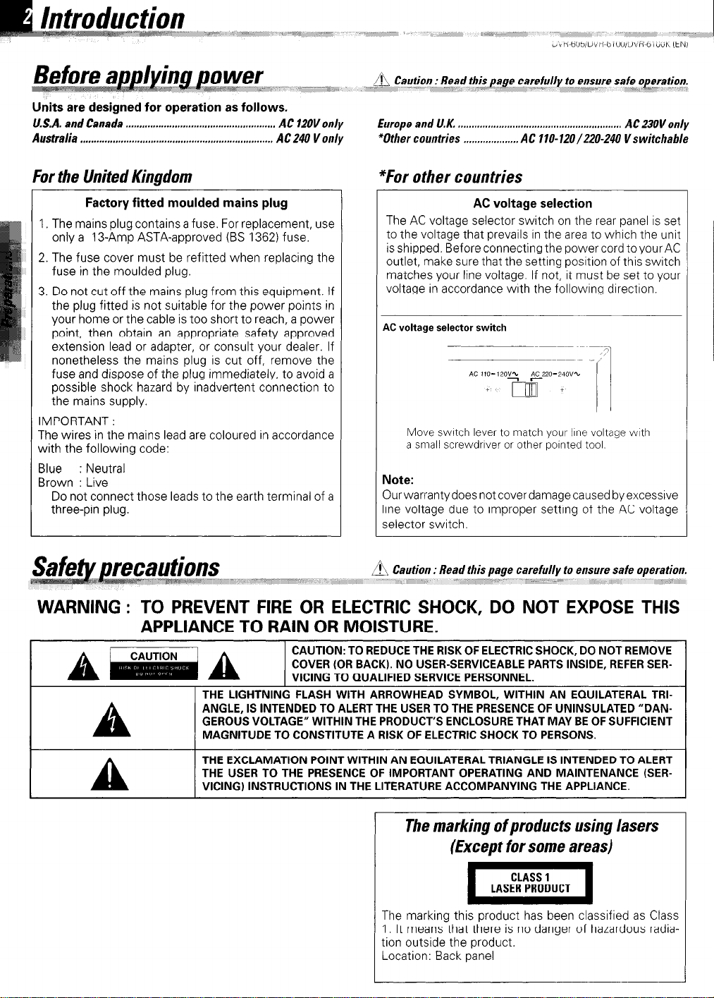
Units are designed for operation as follows.
U.S.A. and Canada
Australia
. . . . . . . . . . . . . . . . . . . . . . . . . . . . . . . . . . . . . . . . . . . . . . . . . . . . . . . . . . . . . . . . . . . . . . . AC 240 V only
. . . . . . . . . . . . . . . . . . . . . . . . . . . . . . . . . . . . . . . . . . . . . . . . . . . . . . . AC 120V only
(,,,,,,,,,, ,,,,e, f&;,,*
Europe and U.K. ,..........,,.,...,.....,............,....,,.......,.,...... AC 23011 only
*Other countries ,....,..,,.......,.. AC 1 IO- 120/220-240 V s witchable
For the United Kingdom
Factory fitted moulded mains plug AC voltage selection
I. The mains plug contains a fuse. For replacement, use
only a 13-Amp ASTA-approved (BS 1362) fuse.
2. The fuse cover must be refitted when replacing the
fuse in the moulded plug.
3. Do not cut off the mains plug from this equipment. If
the plug fitted is not suitable for the power points in
your home or the cable is too short to reach, a power
point, then obtain an appropriate safety approved
extension lead or adapter, or consult your dealer. If
nonetheless the mains plug is cut off, remove the
fuse and dispose of the plug immediately, to avoid a
possible shock hazard by inadvertent connection to
the mains supply.
IMPORTANT:
The wires in the mains lead are coloured in accordance
with the following code:
Blue : Neutral
Brown : Live
Do not connect those leads to the earth terminal of a
three-pin plug.
a&ions
“~~~##~~\~\$ I_^ I_ ~~~*~“<q““” ,,,,,, em;<7 ,, ;
*For other countries
The AC voltage selector switch on the rear panel is set
to the voltage that prevails in the area to which the unit
is shipped. Before connecting the powercord to your AC
outlet, make sure that the setting position of this switch
matches your line voltage. If not, it must be set to your
voltage in accordance with the following direction.
4C voltage selector switch
Move switch lever to match your lbne voltage with
a small screwdnver or other nolnted tool.
Vote:
Xrwarrantydoesnotcoverdamagecausedbyexcessive
ine voltage due to improper setting of the AC voltage
<elector switch.
A Caution : Read this page carefully to ensure safe operation.
,, ,, ,,,,____,,,,,,,,,,,, ;,, . .,.:,, .__ ,.i”, ,,
i <,i
WARNING : TO PREVENT FIRE OR ELECTRIC SHOCK, DO NOT EXPOSE THIS
APPLIANCE TO RAIN OR MOISTURE.
THE LIGHTNING FLASH WITH ARROWHEAD SYMBOL, WITHIN AN EQUILATERAL TRIANGLE, IS INTENDED TO ALERT THE USER TO THE PRESENCE OF UNINSULATED “DANGEROUS VOLTAGE” WITHIN THE PRODUCT’S ENCLOSURE THAT MAY BE OF SUFFICIENT
MAGNITUDE TO CONSTITUTE A RISK OF ELECTRIC SHOCK TO PERSONS.
THE EXCLAMATION POINT WITHIN AN EQUILATERAL TRIANGLE IS INTENDED TO ALERT
THE USER TO THE PRESENCE OF IMPORTANT OPERATING AND MAINTENANCE (SER-
a
VICING) INSTRUCTIONS IN THE LITERATURE ACCOMPANYING THE APPLIANCE.
The marking of products using lasers
(Except for some areas)
The marking this product has been classified as Class
1. It means that there is no danger of hazardous radiation outside the product.
Location: Back panel
Page 3
,__‘__ is,* 3 WAe/e&,,,2
#m&&S,. .;r;ri-:~~~~~~~~~~~~“~
DVR-605/DVR-6100/DVR-6100K (EN)
Caution : Read the pages marked /?‘J carefully to ensure safe operation.
Preparations
Introduction
‘!fi Before applying power
,!& Safety precautions..
Accessories
......................................................................................
.....................................................
...........................................................
...............................................................................
CHANNEL SPACE setting (Except for the U.S.A., Canada,
U.K., Europe and Australia)
A IMPORTANT SAFEGUARDS
Special features
Reference
Maintenance
information
Discs
..............................................................................
.........................................................................................
....................................................................................
............................................................................
Types of playable discs
Unplayable discs
......................................................................
Icons on the DVD discs
Region codes
.................................................................................
Region codes in the world
...............................................
....................................................
...........................................................
............................................................
....................................................
Examples of TVscreen display of each video format
Video formats
.................................................................................
Video formats of DVLJ discs that can be played on this unit
LlSystem
Connections ..............................................................
Loudspeakers
..........................................................................
AM loop antenna ....................................................................
FM antenna ..............................................................................
Connecting to a TV .................................................................
...........................................
Connecting to a Satellite
Connecting to Audio video
Tuner
equipments
.............................
Connecting a Camcorder or Video game machine..
Controls
Operation
and indicators.. ..............................................................
.............................................. 17
of remote control
unit..
2
:
4
4
5
7
7
8
9
9
9
9
10
10
......
10
11
...... 11
E
13
13
14
14
15
......... 15
16
Operations
put out some sound .............................................................
Let’s
Basic use method
Changing the Tone
............................................................................................
Dimmer
Receiving
broadcast station
...................................................................
..................................................................
....................................................... 21
Storing the broadcast stations {one-by-one presetting). 22
................. 23
Using RDS function (for Europe and U.K.
PN function (for Europe
Progressive
Playback
Scan (for US and Canada
............................................................................
of disc
and U.K. only) .............................
only)
........................... 25
only).
Basic play ................................................................................
Disc playback features..
the On-screen banner
Using
Selecting a Title
Selecting a Chapter or
Changing the Audio Language
Changing the Subtitle Language..
Changing the Camera angle
Using IntroScan function
........................................................
display.. .......................................
......................................................................
Track.. ..............................................
.............................................
........................................
.................................................
......................................................
Using Bookmarks ...................................................................
Repeat play
..............................................................................
A-B Repeat play ......................................................................
Random play ............................................................................
18
18
19
20
24
26
26
27
28
29
29
30
30
31
31
32
33
33
34
Program play
Menu playback
..................................................................................
..............................................................................
Hierarchical structure of VCD menus
.................................
35
37
37
Examples of operation keys and indications used during
VCD playback
....................................................................
37
Playback without using the menu playback function (In case
of a t?B.C.-compatible VCD) (To PB.C. On or Off)
Enjoying karaoke singing (DVR-61oOK only)
Selecting the Audio
channel.. ..............................................
Controlling the key of the music
Adjust the ECHO level
H/T MASTER function
MP3 function
..................................................................................
............................................................
...........................................................
............................
(KEY CONTROL)
Guidance of MP3 ....................................................................
Playing back MP3
Selecting MP3 files
...................................................................
................................................................
MP3 Repeat play .....................................................................
MP3 Random play ...................................................................
MP3 Program play ..................................................................
Up functions
Set
Set up menu
Select Audio language
Select Subtitle Language
Select Menu Language
Select Rating
Password
Naspect..
Setting up listen mode
What are listen modes?.
To set the LISTEN mode manually
Speaker
Level setting using a
Changing
............................................................................
.............................................................................
.........................................................
......................................................
..........................................................
...........................................................................
.................................................................................
................................................................................
.................................................................
.......................................................
.......................................
setting .............................................................................
music source.. ...................................
the INPUT MODE..
.......................................................
............. 38
39
39
............ 39
40
40
41
41
42
43
44
44
45
46
46
47
47
48
48
49
51
52
52
53
54
56
56
Control of a different device with the accessory remote
controller.. ................................................................................
Register the setup codes for your audio and video
Operating other devices
Setup code table (except for U.S.A.
Setup code table (for U.S.A. and Canada only)
........................................................
and Canada)
................. 59
Keys which can be used to operate connected devices
57
.......... 57
57
............ 58
63
Knowledge
Knowledge
case of difficulty .......................................................................
In
Specifications..
.....................................................................................
DVD menu language code list
.............................................. 64
..............................................................................
64
65
68
Page 4
Unpacking
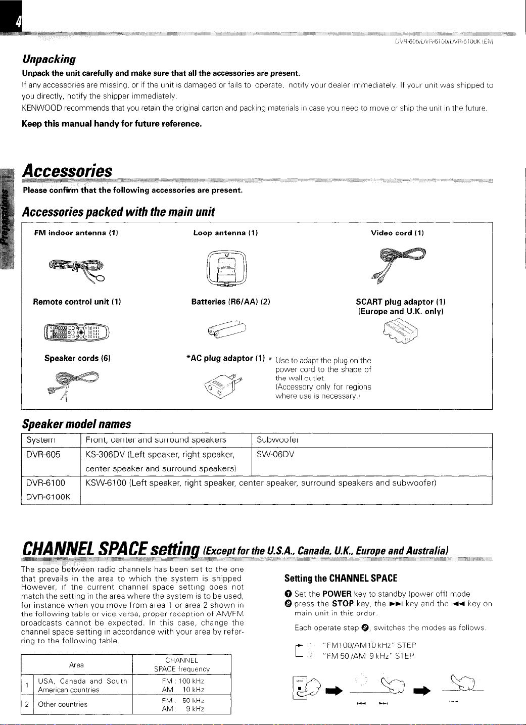
Unpack the unit carefully and make sure that all the accessories are present.
If any accessories are mrssing, or if the unit IS damaged or falls to operate, notrfy your dealer rmmedrately If yolrr unrt was shipped to
you directly, notify the shipper immediately
KENWOOD recommends that you retain the original carton and packing materrals In case you need to move or shop the unit In the future.
Keep this manual handy for future reference.
,A:c*@qw ,~,,,,,Y”““‘~~~~~~,~, , ,w: ,,_ /, ,, ,,/ ,,,, we,, ,, ,, ,,, ,, ,_,, ,, _
Please confirm that the following accessories are present.
! Accessories packed with the main unit
/
FM indoor antenna (1) Loop antenna (I)
Video cord (I )
Remote control unit (1) Batteries (RG/AA) (2) SCART plug adaptor (1)
Speaker cords (6)
*AC
Plug
adaptor (1) * Use to adapt the plug on the
power cord to the shape of
the wall outlet
(Accessory only for regrons
where use IS necessary.)
(Europe and U.K. only)
Speaker model names
1 System
DVR-605 KS-306DV (Left speaker, right speaker,
DVR-6100
DVR-61 OOK
CH,NM” SPACE setiing (Except for the U.S.A., Canada, U.K., Europe and Australia)
HH,H
The space between radio channels has been set to the one
that prevails in the area to which the system IS shipped
However, if the current channel space setting does not
match the setting in the area where the system IS to be used,
for instance when vou move from area 1 or area 2 shown In
the followrng table or vrce versa, proper receptron of AM/FM
broadcasts cannot be expected. In this case, change the
channel space setting In accordance wrth your area by referring to the following table.
* 1 USA, Canada and South
’ Amencan countrres
2 Other countrres
I I
1 Front, center and surround speakers 1 Subwoofer
center speaker and surround speakers)
KSW-6100 (Left speaker, right speaker, center speaker, surround speakers and subwoofer)
T,w####gqe AI.--_, \*$~‘~#p~~m*~;p~$ $y ,,,\,\, “‘*-> ,p<, :s W<““r(@!W ,,,,,, ,*
Area
I
CHANNEL
SPACE frequency
FM 100 kHr
AM 10 kHz
FM 50kHr
AM 9 kHz I
SW-OGDV
~~~~~~~~~~ ;#i, I ?,%; j I I ?,/ ,, _I
Setting the CHANNEL SPACE
0
Set the
Q press the
POWER
STOP
mart- unrt in this order.
Each operate step 0, swatches the modes as follows
“FMlOO/AMlb kHz” STEP
“FM 50 /AM 9 kHz” STEP
I ,,,., ,,.( (((,, ((( ,,,,,, _,*, “‘ ,,,,_ _
key to standby (power off) mode
key, the ))I key and the 144 key on
Page 5
A Caution : Read this page carefully to ensure
DVR-605/DVR-6100/DVR-6100K (EN)
Please read all of the safety and operatrng rnstructrons before
operatrng thus appliance. Adhere to all warnings on the appliance
and In the rnstruction manual. Follow all the safety and operatrng
Instructions. These safety and operatrng rnstructrons should be
retained for future reference.
1. Power sources - The applrance should be connected to a
power supply only of the type described in the Instruction
manual or as marked on the appliance. If you are not sure of
the type of power supply to your home, consult your appliance
dealer or local power company. For appliances Intended to
operate from battery power, or other sources, refer to the
instructron manual.
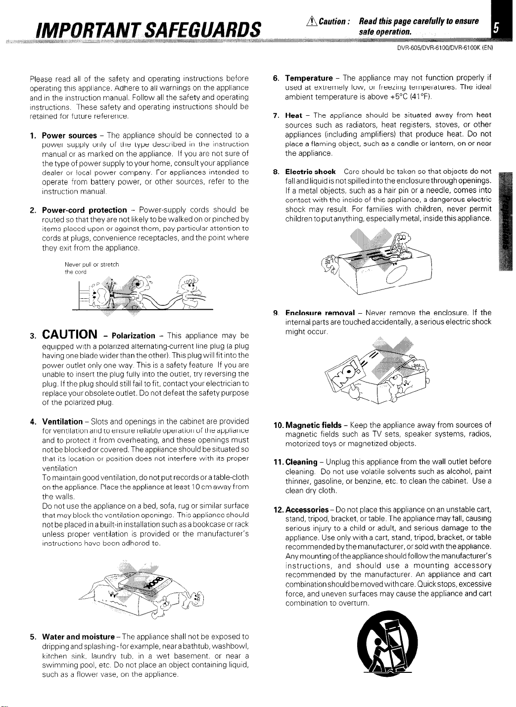
2. Power-cord protection - Power-supply cords should be
routed so that they are not likely to be walked on or pinched by
Items placed upon or against them, pay partrcular attention to
cords at plugs, convenrence receptacles, and the point where
they exrt from the applrance.
Never
pull
or stretch
the cord
3. CAUTION - P I
o arization - This appliance may be
equipped with a polarized alternating-current line plug (a plug
having one blade wrder than the other). Thus plug will fit into the
power outlet only one way This is a safety feature If you are
unable to Insert the plug fully Into the outlet, try reversing the
plug. If the plug should still fall to fit, contact your electrician to
replace your obsolete outlet. Do not defeat the safety purpose
of the polarized plug.
Temperature - The appliance may not function properly if
used at extremely low, or freezing temperatures. The ideal
ambient temperature is above +5”C (41°F).
Heat - The appliance should be situated away from heat
sources such as radiators, heat registers, stoves, or other
appliances (including amplifiers) that produce heat. Do not
place a flaming object, such as a candle or lantern, on or near
the appliance.
Electric shock - Care should be taken so that objects do not
fall and liquid is not spilled into the enclosure through openings.
If a metal objects, such as a hair pin or a needle, comes into
contact with the inside of this appliance, a dangerous electric
shock may result. For families with children, never permit
children to put anything, especially metal, inside thisappliance.
Enclosure removal - Never remove the enclosure. If the
Internal parts are touched accidentally, a serious electric shock
mraht occur.
4. Ventilation - Slots and openings in the cabrnet are provided
for ventrlatron and to ensure reliable operation of the applrance
and to protect It from overheating, and these openings must
not be blocked or covered. The appliance should be situated so
that Its locatron or position does not interfere with its proper
ventilation
To marntarn goodventilatron, do not put records or a table-cloth
on the appliance Place the appliance at least 10 cm away from
the walls.
Do not use the applrance on a bed, sofa, rug or srmrlar surface
that may block the ventilation openings. This appliance should
not be placed In a built-in installation such as a bookcase or rack
unless proper ventilation is provided or the manufacturer’s
rnstructrons have been adhered to.
5. Water and moisture-The appliance shall not be exposed to
dripprngandsplashlng-forexample, neara bathtub, washbowl,
krtchen srnk, laundry tub, In a wet basement, or near a
swrmmrng pool, etc Do not place an object contarning Irquid,
such as a flower vase, on the appliance.
10. Magnetic fields - Keep the appliance away from sources of
magnetic fields such as TV sets, speaker systems, radios,
motorized toys or magnetized objects.
11. Cleaning - Unplug this appliance from the wall outlet before
cleaning. Do not use volatile solvents such as alcohol, paint
thinner, gasoline, or benzene, etc. to clean the cabinet. Use a
clean dry cloth.
12. Accessories- Do not place this appliance on an unstable cart,
stand, tripod, bracket, or table. The appliance may fall, causing
serious injury to a child or adult, and serious damage to the
appliance. Use only with a cart, stand, tripod, bracket, or table
recommended by the manufacturer, or sold with the appliance.
Anymountingoftheapplianceshouldfollowthemanufacturer’s
instructions, and should use a mounting accessory
recommended by the manufacturer. An appliance and cart
combination should be movedwrth care. Quick stops, excessive
force, and uneven surfaces may cause the appliance and cart
combrnation to overturn.
Page 6
13.Lightning - For added protectlon for this appliance during a
lightning storm, or when it IS left unattended and unused for
long periods of time, unplug It from the wall outlet and
disconnect the antenna or cable system. This will prevent
damage to the appliance due to llghtnlng and power-l:ne
surges.
l&Power lines - An outsIde antenna systern should not be
located in the vlclnlty of overhead power lines or other electric
light or power circuits, or where It can fall Into such power lines
orclrcults When installlng an outsideantenna system extreme
care shoLlld be taken to keep from touching such power lanes
or circuits as contact with them might be fatal
14.Abnormal smell - If an abnormal smell or smoke IS
detected, immediately turn the power OFF and unplug
the appliance from the wall outlet. Contact your dealer 01
nearest service center
15.Damage requiring service - The appliance should be
serviced by qualified service personnel when:
A. The power-supply cord or the plug has been
damaged.
Objects have fallen, or liquid has been spllled Into
B.
the appliance
The appliance has been exposed to rain or water
C.
D. The appliance does not appear to operate normally
by followlng the instruction manual. Adjust only those controls
that are covered by the InstructIon manual as an Improper
adjustment of other controls may result In damage and WIII
often require extensive work by a quaIlfled technicIan to
restore the appliance to its normal operation.
E. The appliance has been dropped, or the enclosure
damaged.
F. The appliance exhibits a marked change in performance
lG.Servicing - The user should not attempt to service the
appliance beyond that described in the instruction
manual. All other servicing should be referred to quaIlfled
service personnel.
19.AC outlets - Do not connect other audio equipment
with a power consumption larger than that specified to
the AC outlet on the rear panel. Never connect other
electrical appliances, such as an Iron or toaster, to It to
prevent fire or electric shock
20. Overloading-Do not overload wall outlets, extension cords,
or integral convenience receptacles as this can reslllt In a risk
of fire or electric shock
21. Attachment - Do not use attachments not recommended by
the appliance manufacturer as they may cause hazards
22. Replacement parts-When replacement parts are required,
be sure the service technIcIan has used replacement parts
specified bythemanufacturerorhavethesamecharacterlstlcs
as the orlglnal parts Unauthorized substltutlons [nay result
flre, electric shock, or other hazards.
23. Safety check - Upon completion of any service or repalrs to
this appliance, ask the service technIcIan to perform safety
checks to determine that the appliance IS 111 pi-oper operating
condltlon.
II?
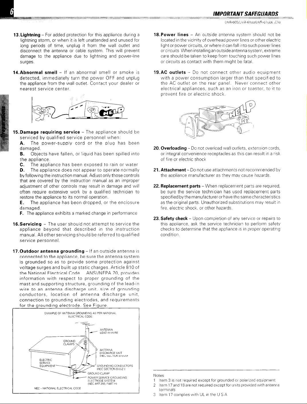
17.0utdoor antenna grounding - If an outslde antenna IS
connected to the appliance, be sure the antenna system
is grounded so as to provide some protection against
voltage surges and built up static charges Article 810 of
the National Electrical Code
ANSl/NFPA 70, provides
information with respect to proper grounding of the
mast and supporting structure, grounding of the lead-In
wire to an antenna discharge unit. size of grounding
conductors, location of antenna discharge unit,
connection to grounding electrodes, and requirements
for the grounding electrode. See Figure.
Notes
1 Iten? 3 IS not required except for groilnded 01 polarlied equipn?ent
2 Item 17 and 18 are not required except for units provided with at?tel?na
teirmnals
3 ltetn 17 comolies with UL in the U S A
Page 7
1 ’ “*-/ ,*a,, :
.,::.r /__
/ ‘%z<<~~p 1
DVR-605/DVR-6100/DVR-6lOOK (EN)
,_ _, _ :$:‘i,i :’
: ,‘A,, _ ,,,,,, ,,m” ,,,, / I //P-P ‘b
,, &i: ,~
,,, ,,a>* ,,,,,,,,, av&/m
This document classifies the applications of each feature using the following marks
@) : Description of a feature that can be used with DVD.
@ : Description of a feature that can be used with CD.
Q@ : Description of a feature that can be used with VCD.
@ Higher video quality than S-VHS video and LaserDisc
m 1 Higher audio quality than music CD
@ @@ 1 Graphical user interface (GUI) compatibility
@) 1 Versatile DVD playback features
m @ The D1/R-605/DVR-6100/6100K offers DTS decoder.
@ @D @I@ Dolby Pro Logic II decoder.
::%3B& %*mmw*
Caution on condensation
Condensation (of dew) may occur rnsrde the unrt when there IS
a great difference in temperature between thus unit and the
outsrde
Thus unrt may not function properly If condensatron occurs In
this case, leave the unit for a few hours, and restart the operation after the condensatron has dried up.
Be specially cautious against condensation in a following circumstances:
When this unit IS carried from one place to another across a large
difference In temperature, when the humldlty in the room where
this unit IS installed Increases, etc.
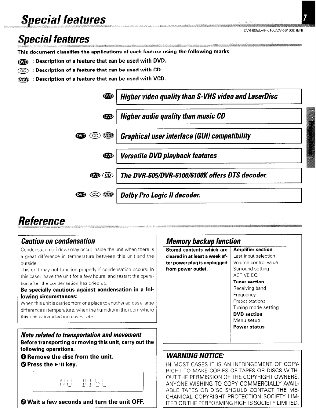
Note related to transportation and movement
Before transporting or moving this unit, carry out the
following operations.
0 Remove the disc from the unit.
0 Press the ./II key.
I_- l\i/ ;;;;;j j:j : .-;:T]
0 Wait a few seconds and turn the unit OFF.
Memorv backup function
Stored contents which are
cleared in at least a week after power plug is unplugged
From power outlet.
I
.
Amplifier section
Last input selection
Volume control value
Surround setting
ACTIVE EQ
Tuner section
Receiving band
Frequency
Preset stations
Tuning mode setting
DVD section
Menu setup
Power status
WARNING NOTICE:
IN MOST CASES IT IS AN INFRINGEMENT OF COPYRIGHT TO MAKE COPIES OF TAPES OR DISCS WITH-
OUTTHE PERMISSION OF THE COPYRIGHT OWNERS.
ANYONE WISHING TO COPY COMMERCIALLY AVAILABLE TAPES OR DISC SHOULD CONTACT THE MECHANICAL COPYRIGHT PROTECTION SOCIETY LIM-
ITED OR THE PERFORMING RIGHTS SOCIETY LIMITED.
Page 8
Do not use contact cleaners because It could cause a malfunction.
Be specrally careful not to use contact cleaners containrng 011, for
they may deform the plastrc component.
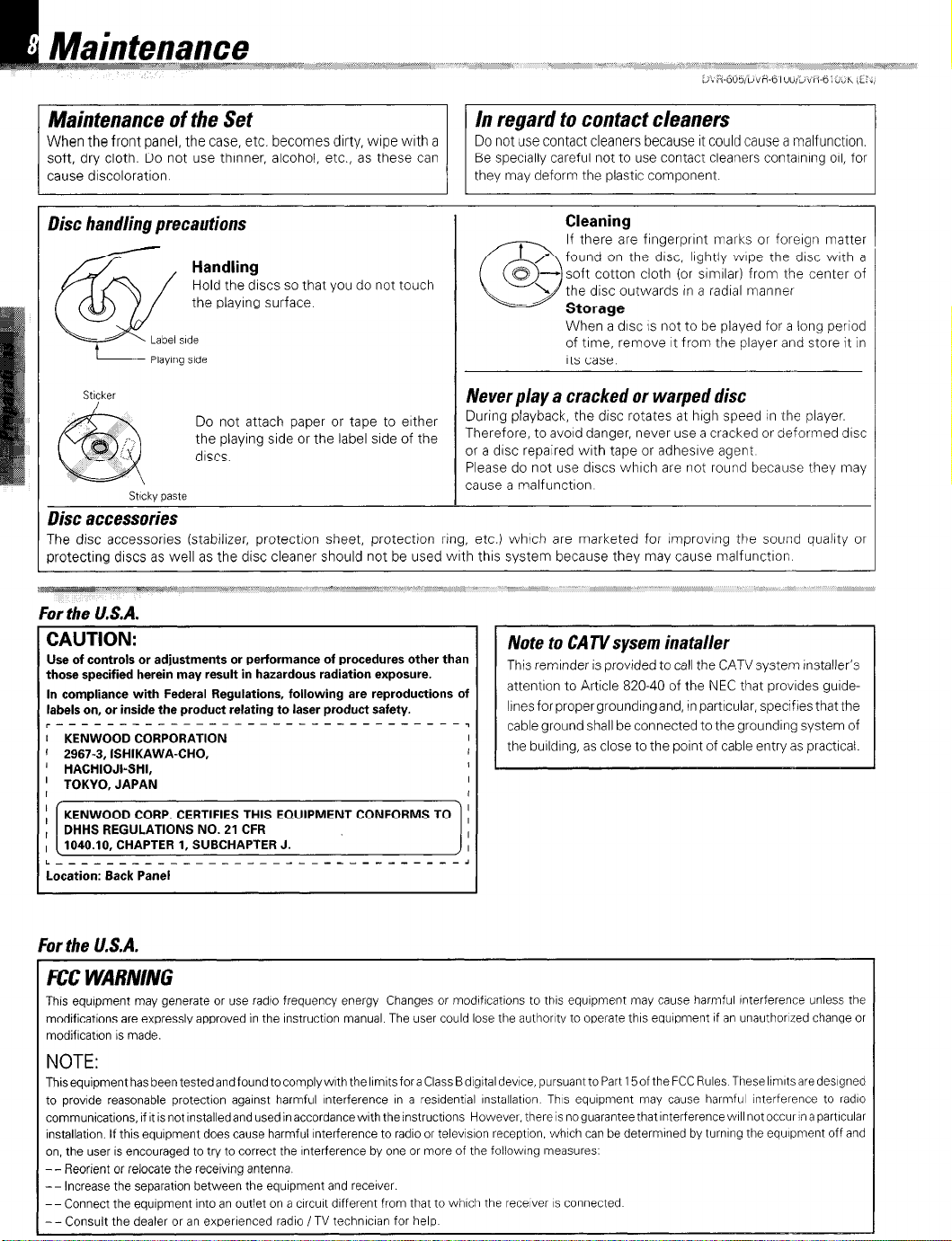
Disc handling precautions
Handling
Hold the discs so that you do not touch
the playrng surface.
c!ti?
t :a:::‘f:,e
Strcker
Do not attach paper or tape to erther
the playing side or the label side of the
discs.
Strcky paste
(3
Never play a cracked or warped disc
During playback, the disc rotates at high speed in the player.
Therefore, to avoid danger, never use a cracked or deformed disc
or a drsc repaired wrth tape or adhesive agent
Please do not use drscs whrch are not round because they may
cause a malfunctron
Cleaning
If there are frngerprrnt marks or forergn matter
t
/ 0 found on the drsc, lrghtly wrpe the drsc wrth a
0 - soft cotton cloth (or srmrlar) from the center of
L the disc outwards in a radial manner
Storage
When a drsc IS not to be played for a long period
of time, remove It from the player and store it in
Its case.
Disc accessories
The disc accessories (stabilizer, protectron sheet, protection ring, etc.) whrch are marketed for rmprovrng the sound quality or
xotectrng discs as well as the disc cleaner should not be used with this system because they may cause malfunction
For the U.S.A.
CAUTION:
Use of controls or adjustments or performance of procedures other than
those specified herein may result in hazardous radiation exposure.
In compliance with Federal Regulations, following are reproductions of
labels on, or inside the product relating to laser product safety.
~-------------------------------~,
I KENWOOD CORPORATION
’ 2967-3, ISHIKAWA-CHO,
; HACHIOJI-SHI,
, TOKYO, JAPAN
I ,
;
KENWOOD CORP. CERTIFIES THIS EQUIPMENT CONFORMS TO I
, DHHS REGULATIONS NO. 21 CFR
, 1040.10, CHAPTER 1, SUBCHAPTER J.
L----------------_-~_---_--~~~~~~~~~~,
Location: Back Panel
L
Note to CATVsysem installer
This reminder is provided to call the CATVsystem Installer’s
attentron to Article 820-40 of the NEC that provides gurde-
lrnesforpropergroundrngand, rnpartrcular, speclfresthatthe
cable ground shall be connected to the groundrng system of
I
the building, as close to the point of cable entry as practrcal.
I
I
I
I
I
I
-I
For the U.S.A.
1 FCC WARNING
This equrpment may generate or use radro frequency energy Changes or modrfrcatrons to thus equrpment may cause harmful rnterference unless the
modifications are expressly approved in the rnstruction manual The user could lose the authority to operate this equipment If an unauthorized change or
modifrcatron IS made.
1 NOTE:
Thisequipmenthasbeentestedandfoundtocomplyw~ththel~m~tsforaClassBd~g~taldev~ce,pursuanttoPart 15oftheFCCRules Theselrmrtsaredesrgned
to provide reasonable protection against harmful Interference rn a residential rnstallatron. Thus equipment may cause harmful interference to radio
communications, if It is not rnstalledand used in accordance wrth the rnstructrons
installation. If this equipment does cause harmful Interference to radio or telewsron reception. which can be determrned by turnrng the equrpment off and
on, the user IS encouraged to try to correct the Interference by one or more of the followrng measures.
-- Reorient or relocate the recervrng antenna.
-- Increase the separation between the equipment and recerver.
--Connect the equrpment into an outlet on a crrcurt different from that to whrch the recerver IS connected
- - Consult the dealer or an experienced radio /TV technrcran for help
However, there IS noguarantee that Interference wrll not occur in a partrcular
Page 9
DVR-605/DVR-6 1 OOIDVR-61 OOK (ENI
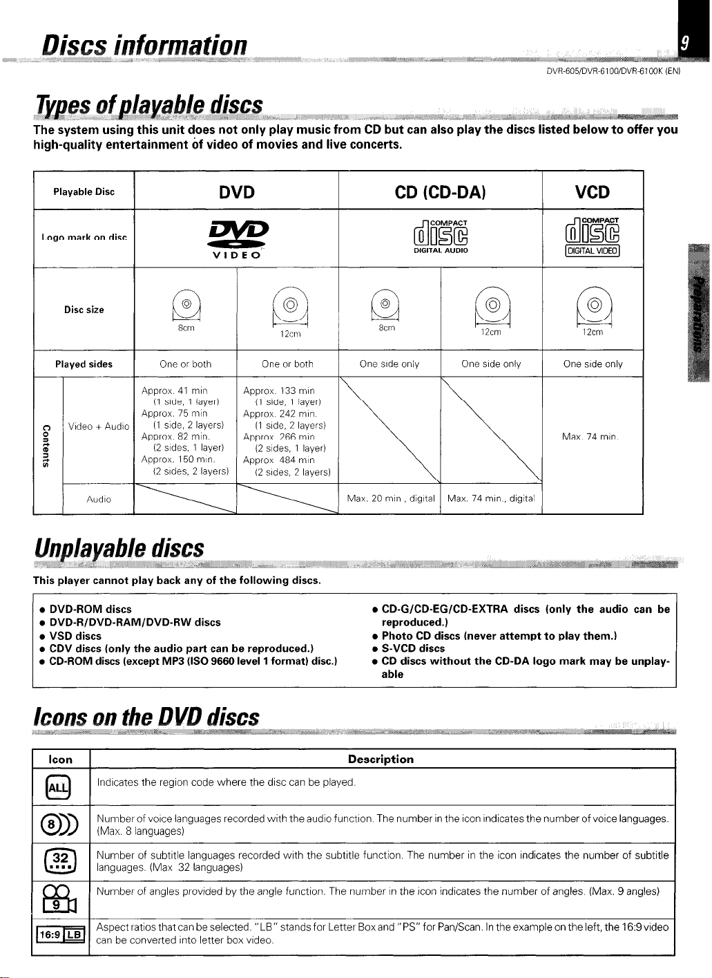
The system using this unit does not only play music from CD but can also play the discs listed below to offer you
high-quality entertainment 6f video of movies and live concerts.
Playable Disc
Logo mark on disc
Disc size
Played sides
Video + Audio
Audio
6:
Approx 41 rmn
(1 side, 1 layer)
Approx. 75 tmn
11 side. 2 layers)
Approx 82 rmn.
12 sides, 1 layer)
Approx. 150 rmn.
I2
sides. 2 layers)
G2
8cm
or both
DVD
VIDEO’
One
or both
4pprox 133 mm
(I srde, 1 layer)
4pprox 242 mm
(I side, 2 layers)
4pprox. 266 mm
(2
sides, 1 layer)
4pprox 484 rmn
(2 srdes, 2 layers)
This player cannot play back any of the following discs.
CD (CD-DA)
8
Q
8crn
One side only One side only One srde only One
Max. 20 min digital Max. 74 mm , digltal
VCD
Max. 74 n-In
l
DVD-ROM discs
l
DVD-R/DVD-RAM/DVD-RW discs
l
VSD discs
l
CDV discs (only the audio part can be reproduced.)
l
CD-ROM discs (except MP3 (IS0 9660 level 1 format) disc.)
l
l
l
l
Icon Description
ALL
0
lndrcates the region code where the disc can be played.
Number of vorce languages recorded with the audio functron. The number in the icon Indicates the number of voice languages.
(Max. 8 languages)
Number of subtitle languages recorded wrth the subtitle function. The number in the icon Indicates the number of subtitle
languages. (Max 32 languages)
Number of angles provrded by the angle function. The number In the Icon indicates the number of angles. (Max. 9 angles)
Aspect ratios that can be selected. “LB” stands for Letter Boxand “PS” for Pan/Scan. In the example on the left, the 16:9vrdeo
can be converted Into letter box vrdeo.
CD-G/CD-EGICD-EXTRA discs (only the audio can be
reproduced.)
Photo CD discs (never attempt to play them.)
S-VCD discs
CD discs without the CD-DA logo mark may be unplayable
I
Page 10
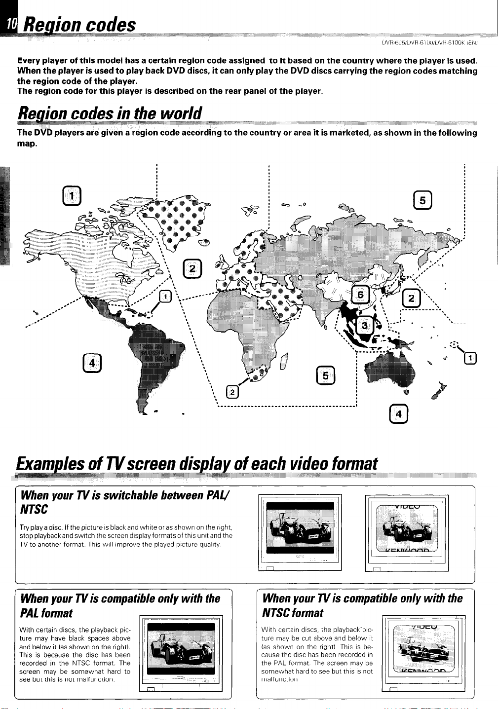
Every player of this model has a certain region code assigned to it based on the country where the player is used.
When the player is used to play back DVD discs, it can only play the DVD discs carrying the region codes matching
the region code of the player.
The region code for this player is described on the rear panel of the player.
the world
-~~~,~~,,,,,,,,,,,~~~~~~~~~~~~~~~~~~~~,,,,~,,, mar#~ I,,‘ .~ y
The DVD players are given a region code according to the country or area it is marketed, as shown in the following
_ ,,,,, __ j ,,,,_ ___ ,, ~~( ,, _ :
I.
When your TV is switchable between PAU
NTSC
Try play a disc. If the picture IS black and white or as shown on the right,
stop playbackand swatch the screen display formats of this unrt and the
TV to another format. Thus will improve the played picture quality
When your TVis compatible only with the
PAL format
With certain discs, the playback picture may have black spaces above
and below it (as shown on the right).
This is because the disc has been
recorded in the NTSC format. The
screen may be somewhat hard to
see but this is not malfunction.
II
When your n/is compa
NTSC format
Wrth certain discs, the playback‘prcture may be cut above and below It
(as shown on the nght) This is because the disc has been recorded rn
the PAL format. The screen may be
somewhat hard to see but this IS not
malfunctron
Page 11
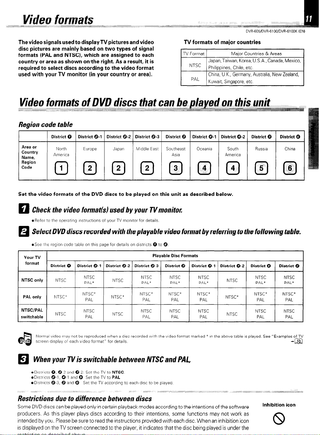
The video signals used to display TV pictures and video
roctrictinn
DC
dncrrihnd
ahn\,o
disc pictures are mainly based on two types of signal
formats (PAL and NTSC), which are assigned to each
country or area as shown on-the right. As a result, it is
required to select discs according to the video format
used with your TV monitor (in your country or area).
Region code table
1 District 0 1 District e-1 1 District O-2 1 District O-3 I District 0 1 District O-1 I District O-2 I District 0 1 District Q 1
TV formats of major countries
Japan, Taiwan, Korea, U.S.A., Canada, Mexico,
China, U.K., Germany, Australia, New Zealand,
Area or
Country
Name,
North
America
Europe
Japan MIddIe East Southeast
Asia
Oceania South
America
Russia China
Set the video formats of the DVD discs to be played on this unit as described below.
Check the video format(s) used by your n/monitor.
q
*Refer to the operating lnstructlons of your TV monitor for details.
Select DVD discs recorded with the playable video format by referring to the following table.
H
@See tile region code table on this page for details on dlstrlcts 0 to 0.
Your TV
format
NTSC only
PAL only
NTSCIPAL
switchable
District 0 District O-1 District o-2 District O-3 District 0
NTSC
NTSC’
NTSC
NTSC
PAL*
NTSC”
PAL
NTSC
PAL
NTSC
NTSC”
NTSC
Playable Disc Formats
NTSC
PAL*
NTSC”
PAL
NTSC
PAL
NTSC
PAL*
NTSC*
PAL
NTSC
PAL
District O-1 District O-2 District 0 District 0
NTSC
PAL*
NT%*
PAL
NTSC
PAL
NTSC
NTSC”
NTSC
NTSC
PAL*
NTSC”
PAL
NTSC
PAL
NTSC
PAL*
NTSC”
PAL
NTSC
PAL
Normal video may not be reproduced when a disc recorded wth the video format marked * in the above table IS played. See “Examples of TV
screen display of each vtdeo format” for cietalls
When your TV is switchable between NTSC and PAL,
H
l Dlstrlcts 0, O-2 and O-2 Set the TV to NTSC
.D~str~c~s O-1, O-1 and 0 Set the TV to PAL
.D~strlcts O-3, 0 and 0 Set the TV according to each disc to be played
Restrictions due to difference between discs
Some DVD discs can be played only in certain playback modes according to the intentions of the software
producers. As this player plays discs according to their intentions, some functions may not work as
intended by you. Please be sure to read the instructions provided with each disc. When an inhibition icon
is displayed on the lV screen connected to the player, it indicates that the disc being played is under the
-@a
Inhibition icon
Page 12
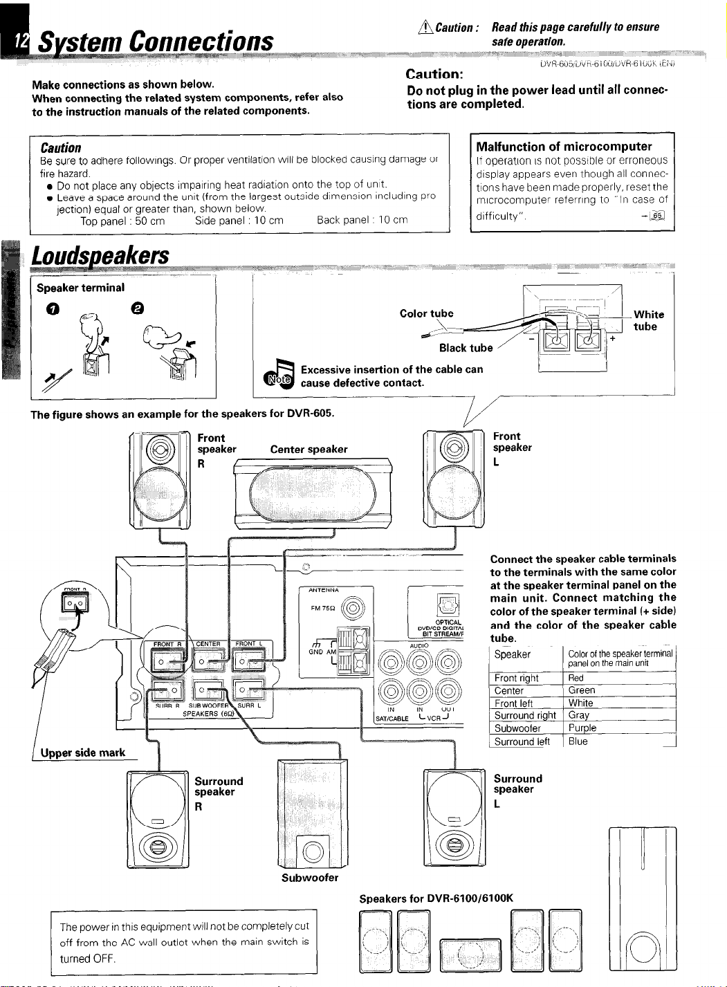
Make connections as shown below.
When connecting the related system components, refer also
to the instruction manuals of the related components.
Do not plug in the power lead
tions are completed.
until
all connec-
Caution
Be sure to adhere followings. Or proper ventilation WI/ be blocked causrng damage or
fire hazard.
. Do not place any objects imparrrng heat radration onto the top of unt.
l
Leave a space around the unrt (from the largest outside dimensron rncludrng pro-
lection) equal or greater than, shown below
Top panel : 50 cm
I ’
The figure shows an example for the speakers for DVR-605.
Side panel : 10 cm
I
I
Center speaker
Back panel 10 cm
Excessive insertion of the cable can
cause defective contact.
Malfunction of microcomputer
If operation IS not possible or erroneous
drsplay appears even though all connections have been made properly, reset the
mrcrocomputer referrrng to “In case of
drfficulty” -I&
tube
d I
Front
speaker
L
Surround
speaker
R
Subwoofer
The power in this equipment will not be completely cut
off from the AC wall outlet when the main switch is
Connect the speaker cable terminals
to the terminals with the same color
at the speaker terminal panel on the
main unit. Connect matching the
color of the speaker terminal (+ side)
and the color of the speaker cable
tube.
Speaker
Front right
Center
Front left
Surround right Gray
Subwoofer
Surround left Blue
Surround
speaker
L
Speakers for DVR-6100/6100K
Color of the speaker terminal
panel
on the main
Red
Green
White
Purple
unit
Page 13
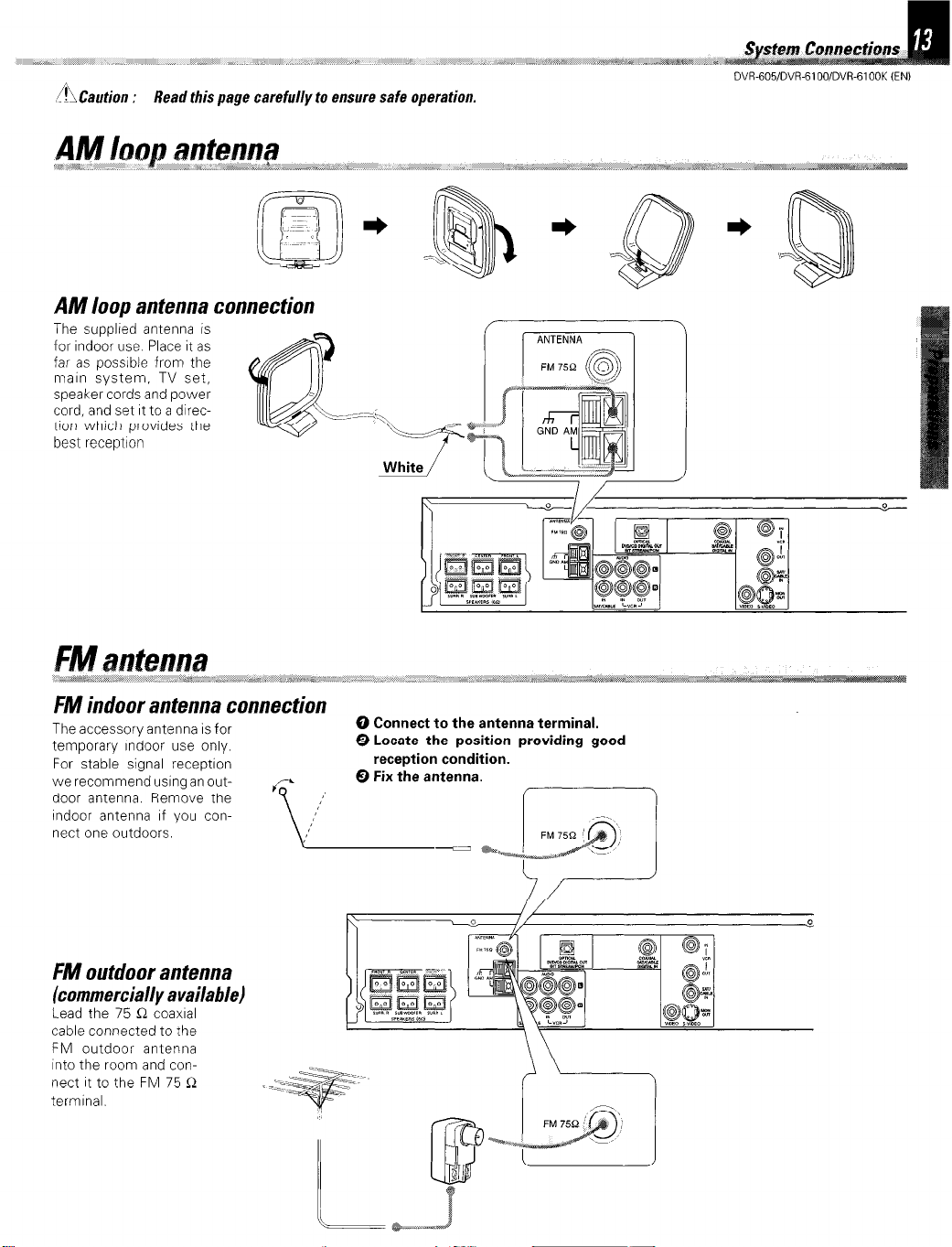
,A Caution :
Read this page carefully to ensure safe operation.
AM loop antenna connection
The supplied antenna is
for indoor use Place it as
far as possrble from the
marn system. TV set,
speaker cords and power
cord, and set It to a dlrectron which provides the
best reception
DVR-605/DVR-6100/DVR-6100K (ENI
FM indoor antenna connection
The accessory antenna is for
temporary Indoor use only.
For stable signal receptron
we recommend usrng an out-
door antenna. Remove the
Indoor antenna If you connect one outdoors.
FM outdoor antenna
(commercially available)
Lead the 75 C2 coaxral
cable connected to the
FM outdoor antenna
Into the room and connect It to the FM 75 R
termrnal.
0 Connect to the antenna terminal.
@ Locate the position providing good
reception condition.
Page 14
“-I,“ ,“. ” “~~~~~~~c,,,,,.~~~ll~~~l,~,~~~~- ._ ,&_/I
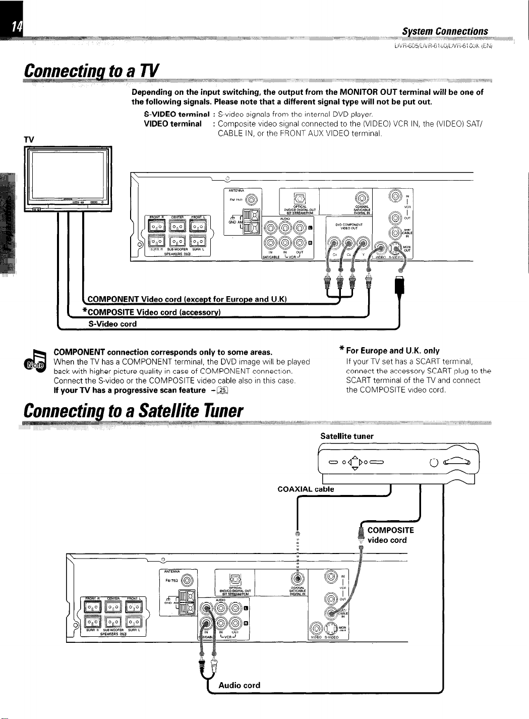
Depending on the input switching, the output from the MONITOR OUT terminal will be one of
the following signals. Please note that a different signal type will not be put out.
S-VIDEO terminal : S-vrdeo signals from the Internal DVD player.
VIDEO terminal : Composrte vrdeo srgnal connected to the (VIDEO) VCR IN, the (VIDEO) SAT/
CABLE IN, or the FRONT AUX VIDEO termrnal.
‘$‘i, ,, ,,
., dr ,,,a;, “$$ ,,, ,,,,,,,,,,, #,,,“, r
_,, I 9 ,, ,,,,,,,,,, 1_ ,,:, i”
COMPONENT connection corresponds only to some areas.
When the TV has a COMPONENT terminal, the DVD Image will be played
back with higher picture quality in case of COMPONENT connectlon.
Connect the S-video or the COMPOSITE video cable also In thus case. SCART termrnal of the TV and connect
If your TV has a progressive scan feature -m the COMPOSITE vrdeo cord.
* For Europe and U.K. only
If your TV set has a SCART terminal,
connect the accessory SCART plug to the
Satellite tuner
[[Z
Audio cord
Page 15
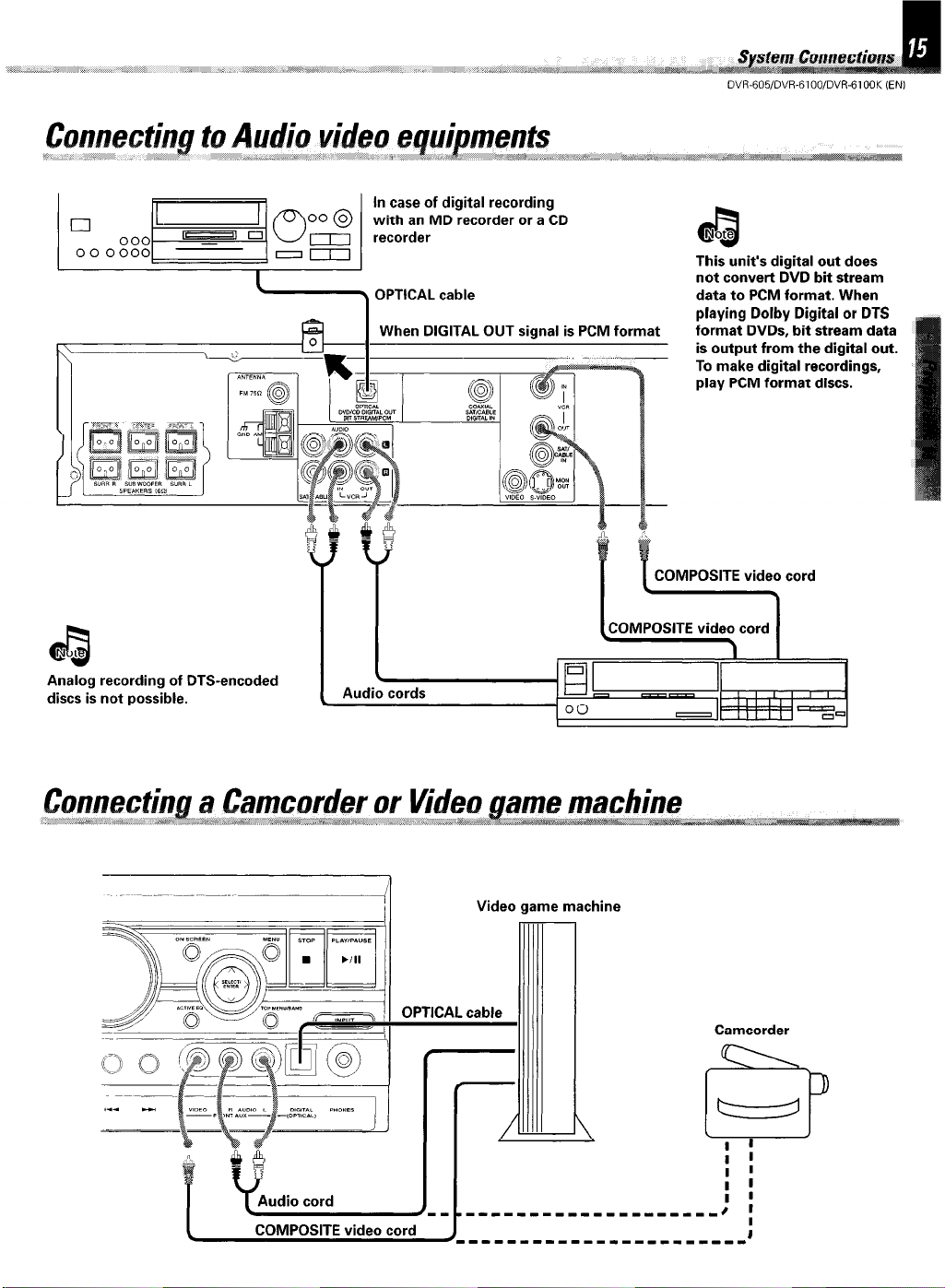
When DIGITAL OUT signal is PCM format
I
DVR-605/DVR-6100/DVR-6lOOK (EN1
This unit’s digital out does
playing Dolby Digital or DTS
format DVDs, bit stream data
is output from the digital out.
To make digital recordings,
play PCM format discs.
COMPOSITE video cord
Note
a
Analog recording of DTS-encoded
discs is not possible.
(COMPOSITE vide\cord 1
I I;=;I II 1
-HI , , , , , , -
Audio cords
Video game machine
00
- IIIII -=a
Camcorder
COMPOSITE video cord
_____-____-----_--_-___(
I
Page 16
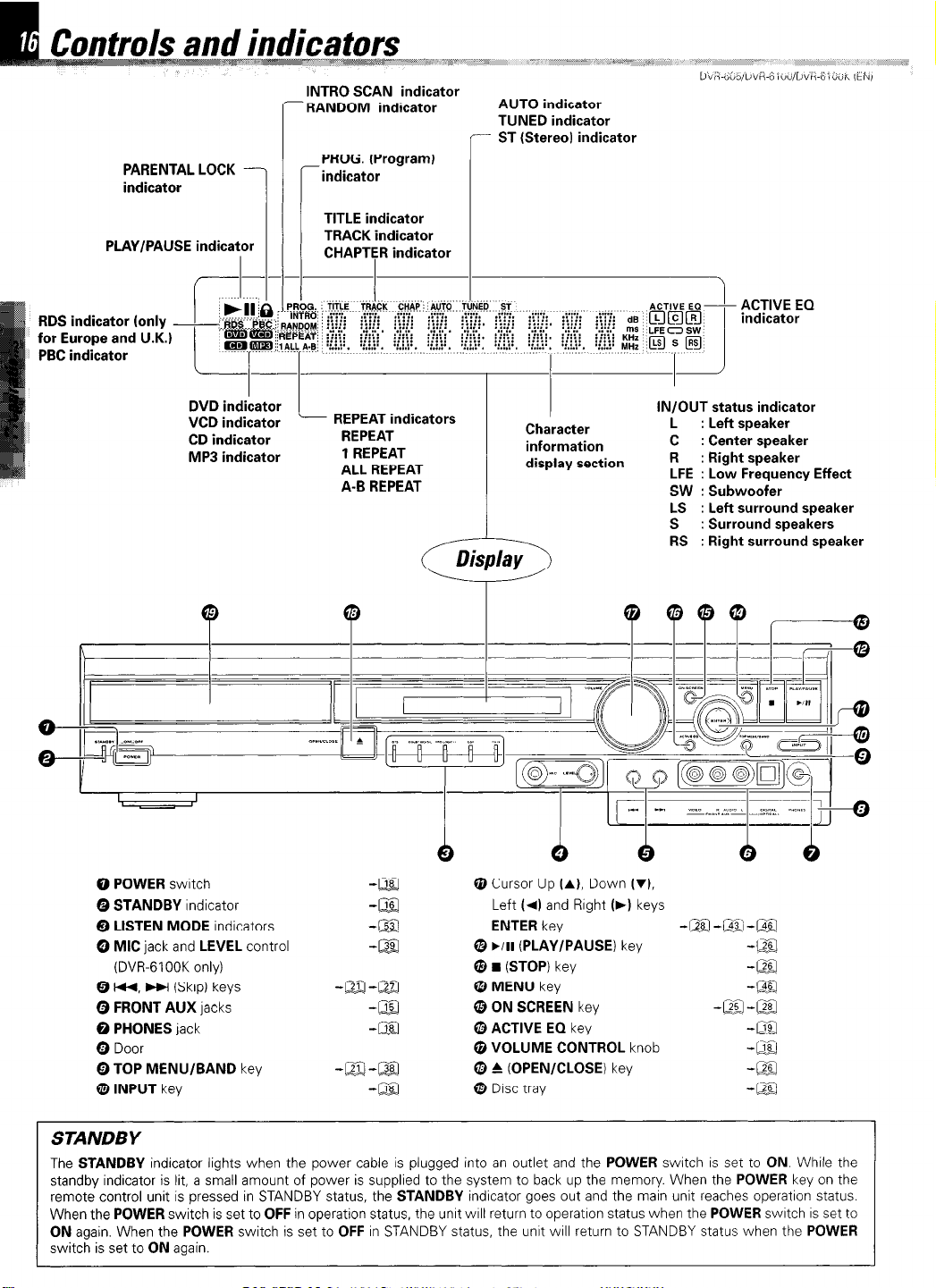
PARENTAL LOCK indicator
PLAY/PAUSE indicator
RDS indicator (only
for Europe and U.K.1
PBC indicator
f--
d,;m&:&:
: ,iiib
e.&
INTRO SCAN indicator
- RANDOM indicator
PROG. (Program)
-indicator
TITLE indicator
TRACK indicator
CHAPTER indicator
-I
s. TITLE TRACK qjfyi Aqq.;.Tu.NE~; ..?g
,a r iii. AG. .:‘:‘:. : yi’;‘: ::..I’:‘: ::.*p: ::..i’:‘: :yi’;‘:
..a.. i:*t;i :::::
‘M. : ::::: , . . . . . . . . . :::::
. . .,
di :::::
. . . . . ::::: ..**.
I
.B, ,:.:.:a. ‘:.:A’. *:.:.:a. G.V.
AUTO indicator
TUNED indicator
- ST (Stereo) indicator
1
.Y.:‘.’ :*;‘:x: .V.:‘.’ **:.:‘. *a:.:‘. ::.:.* .. . .
:::;:. :::;: :::::, :::::
.*.a.
:::::a :::::
*:A:*. 72.:. .
. . . . .
:::::. :::::
,:.:.:’ . ‘:.:.:a.
DVD indicator
VCD indicator
CD indicator
MP3 indicator
0 POWER switch
Q STANDBY indicator
Q LISTEN MODE indicators
0 MIC jack and LEVEL control
(DVR-61 OOK only)
0 H(, ~1 (Skip) keys
Q FRONT AUX jacks
@ PHONES jack
Q Door
0 TOP MENU/BAND key
0 INPUT key
I
- REPEAT indicators
REPEAT
1 REPEAT
ALL REPEAT
A-B REPEAT
I
Character
information
display section
5
Q Cursor Up (A), Down (v),
Left (4) and Rrght (,I keys
ENTER key -m-a-@g
@ ./II (PLAY/PAUSE) key
@ n
(STOP) key
Q MENU key
@ ON SCREEN key
0 ACTIVE EQ key
@ VOLUME CONTROL knob
0 & (OPEN/CLOSE) key
@ DISC tray
IN/OUT status indicator
L : Left speaker
C : Center speaker
R : Right speaker
LFE : Low Frequency Effect
SW : Subwoofer
LS : Left surround speaker
S : Surround speakers
RS : Right surround speaker
-Qg
-4
-m
-lx -cz
--
-m
-.G
-i
422
-
-
STANDBY
The STANDBY indicator lights when the power cable is plugged into an outlet and the POWER switch is set to ON. While the
standby indicator is lit, a small amount of power is supplied to the system to back up the memory. When the POWER key on the
remote control unit is pressed in STANDBY status, the STANDBY indicator goes out and the main unit reaches operation status.
When the POWER switch is set to OFF in operation status, the unrt WIII return to operatron status when the POWER swatch IS set to
ON again. When the POWER switch is set to OFF in STANDBY status, the unit will return to STANDBY status when the POWER
switch is set to ON again.
Page 17
-a
-@
DVR-605/DVR-6100/DVR-6lOOK (EN1
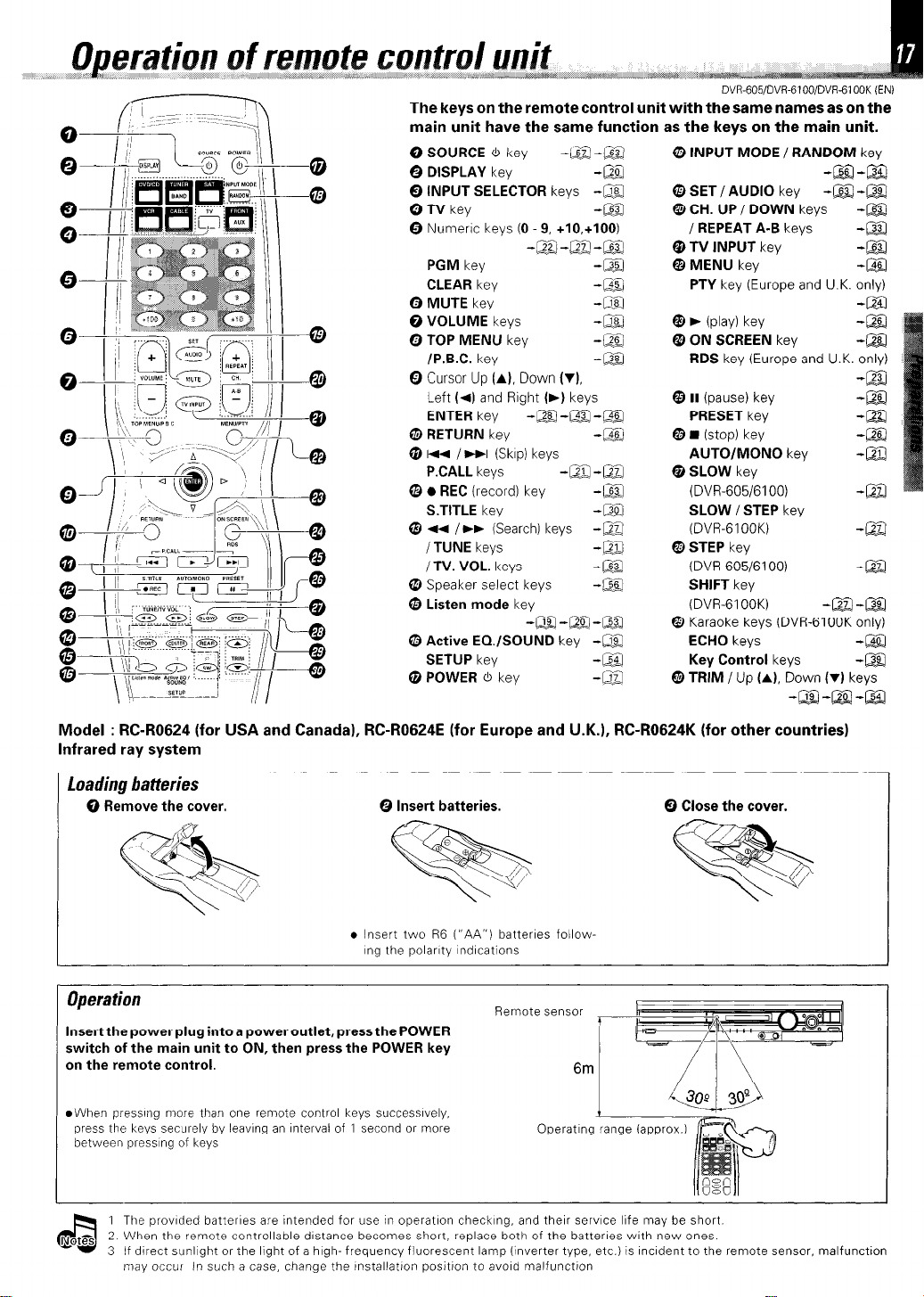
The keys on the remote control unit with the same names as on the
main unit have the same function as the keys on the main unit.
0 SOURCE 6 key
0 DISPLAY key
0 INPUT SELECTOR keys
0 TV key
0 Numeric keys (0 9, +10,+100)
PGM key
CLEAR key
0 MUTE key
0 VOLUME keys
0 TOP MENU key
/P.B.C key
0 Cursor Up (A), Down (‘11,
Left (4) and Right (b) keys
ENTER key -LB-@-m
Q RETURN key
@ HI /WI (Skrp) keys
P.CALL keys
0 l REC (record) key
S.TITLE key
0 ~4 /bb (Search) keys
/ TUNE keys
/TV. VOL. keys
0 Speaker select keys
@ Listen mode key
0 Active EQ./SOUND key -a
SETUP key
@ POWER ti key
-a-m
-lg
-m
-@g
--Egj -@j-J -m
-@
-@Q
-.&
-m
-G
-@g
-&@
-m-m
-!2g
-@q
-n
-m
-m
-g
-m-m-a
-@y
-E
@ INPUT MODE / RANDOM key
@ SET / AUDIO key -a -a
@ CH. UP / DOWN keys
I REPEAT A-B keys
@ TV INPUT key
@ MENU key
PTV key (Europe and U.K. only)
@ b (play) key -@%I
@ ON SCREEN key
RDS key (Europe and U.K. only)
@ II (pause) key
PRESET key
@ H (stop) key
AUTO/MONO key -m
@ SLOW key
(DVR-605/6100)
SLOW /STEP key
(DVR-61 OOK)
@ STEP key
(DVR-605/6100)
SHIFT key
(DVR-61 OOK)
@ Karaoke keys (DVR-6100K only)
ECHO keys
Key Control keys
@ TRIM/Up (A), Down MI keys
-@J-E!
-m
-M
-E
-&zl
-La
-@a
-a!
-m
IE
-El
-m
-El
-m-m
-m
-gg
-LXl-@Q-@jZ
Model : RC-R0624 (for USA and Canada), RC-R0624E (for Europe and U.K.), RC-R0624K (for other countries)
Infrared ray system
Loading batteries
0 Remove the cover. 0 Insert batteries.
. Insert two R6 (“AA”) batteries follow-
~ng the polarity lndlcations
Operation
Insert the power plug into a power outlet, press the POWER
switch of the main unit to ON, then press the POWER key
on the remote control.
@When pressing more than one remote control keys successwely,
press the keys securely by leaving an Interval of 1 second or more
between pressing of keys
1 The provided batteries are intended for use II? operation checking, and their service life may be short
2 When the remote controllable distance becomes short, replace both of the batteries with new ones.
3 If direct sunlIght or the lhght of a high- frequency fluorescent lamp (inverter type. etc.) is lncldent to the remote sensor, malfunction
may occur In such a case, change the lnstallatton positlon to avoid malfunction
Remote sensor
6m
Operating
0 Close the cover.
Page 18
t out some sound
‘q4$ _: j_ .f+ew
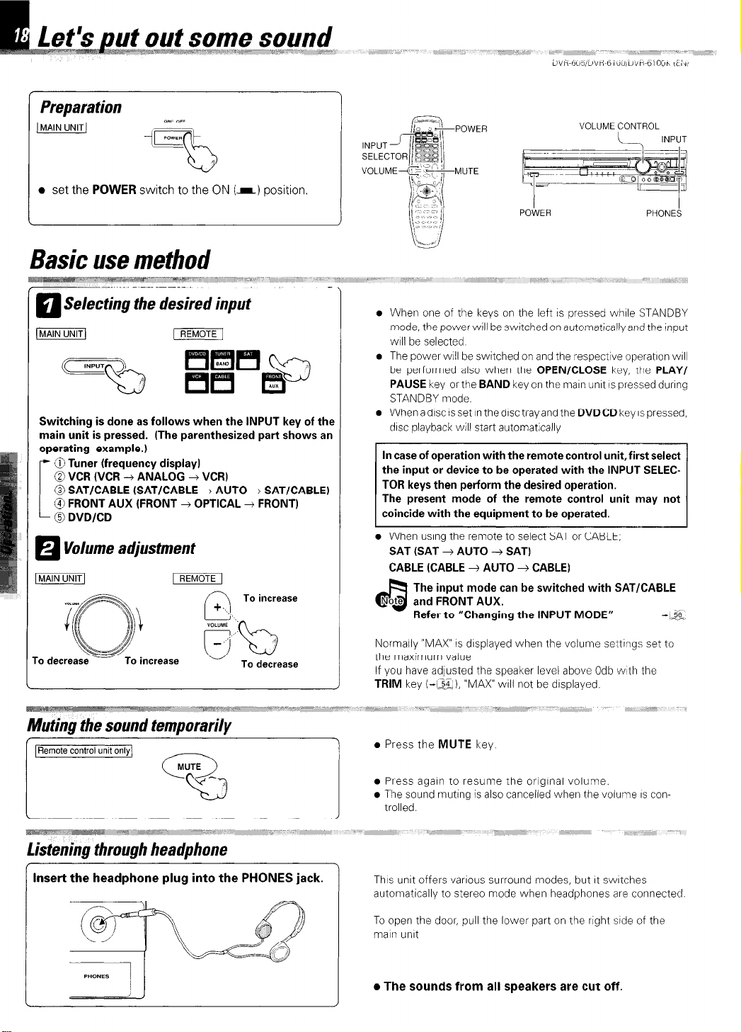
Preparation
)
l
set
the
POWER
ONI OFF
cE=
‘5
switch to the
”
ON
(-1 position
Basic use method
Selecting the desired input
m
Switching is done as follows when the INPUT key of the
main unit is pressed. (The parenthesized part shows an
operating example.)
@Tuner (frequency display)
@ VCR (VCR --+ ANALOG + VCR)
@ SAT/CABLE (SAT/CABLE 3 AUTO + SAT/CABLE)
@ FRONT AUX (FRONT 3 OPTICAL 3 FRONT)
0 DVDICD
Volume adjustment
H
To increase
VOLUME CONTROL
L
I
POWER
l
When one of the keys on the left IS pressed while STANDBY
mode, the power will be switched on automatically and the input
WIII be selected
l
The power WIII be switched on and the respective operation WIII
be performed also when the
PAUSE
key or the
STANDBY mode.
l
WhenadlscIssetlnthedlsctrayandtheDVDCDkeyIspressed,
disc playback will start automatically
The present mode of the remote control unit may not
l
When using the remote to select SAT or CABLE,
SAT (SAT 3 AUTO --f SAT)
CABLE (CABLE 4 AUTO + CABLE)
The input mode can be switched with SAT/CABLE
Note and FRONT AUX.
a
Refer to “Changing the INPUT MODE” -I-$
BAND
OPEN/CLOSE
key on the maln unit IS pressed during
PHONES
key, the
INPUT
I
PLAY/
To decrease
Inset-t the headphone plug into the PHONES jack.
Normally “MAX” IS dlsplayed when the volume settings set to
the maximum value
If you have adjusted the speaker level above Odb with the
TRIM
key (-Lx), “MAX” WIII not be dlsplayed.
l
Press the
l
Press agaln to resume the orIgInal volume.
l
The sound muting IS also canceiled when the volume IS controlled.
This unit offers various surround modes, but It switches
automatically to stereo mode when headphones are connected.
To open the door, pull the lower part on the right side of the
main unit
l
The sounds from all speakers are cut off.
MUTE
key.
Page 19
DVR-605/DVR-6100/DVR-6100K (EN)
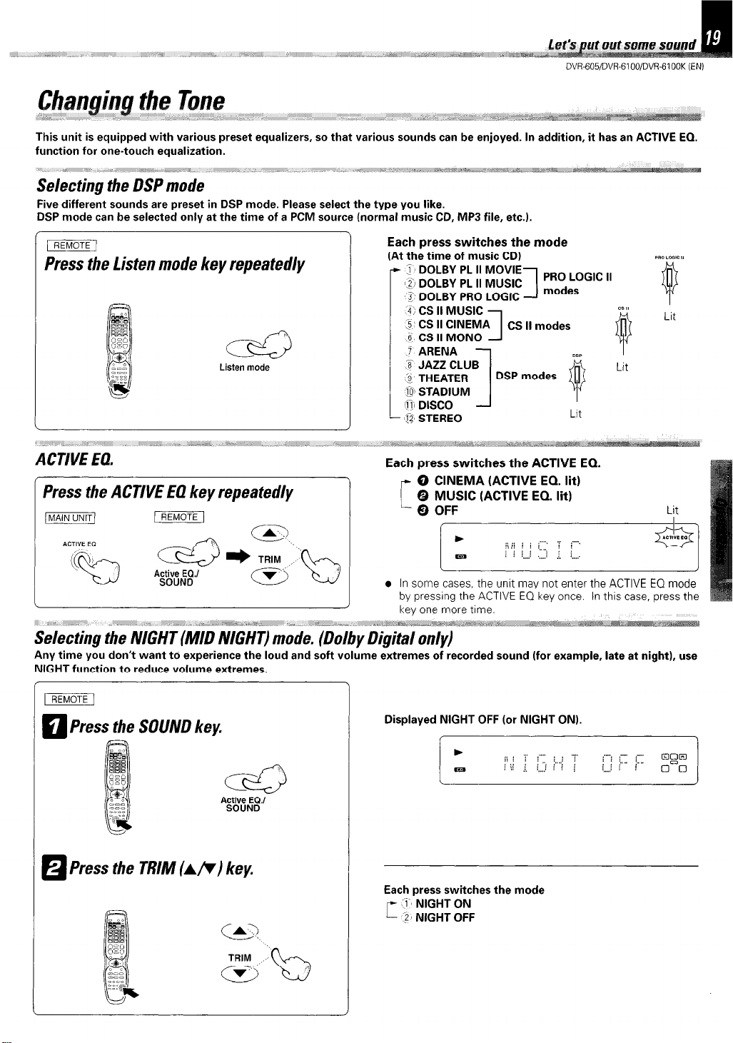
This unit is equipped with various preset equalizers, so that various sounds can be enjoyed. In addition, it has an ACTIVE EQ.
function for one-touch equalization.
Selecting the DSP mode
Five different sounds are preset in DSP mode. Please select the type you like.
DSP mode can be selected only at the time of a PCM source (normal music CD, MP3 file, etc.).
Each press switches the mode
Press the Listen mode key repeatedly
cc2
Listen mode
(At the time of music CD)
- 38 DOLBY PL II MOVIE
1,2i DOLBY PL II MUSIC
2 DOLBY PRO LOGIC
4; CS II MUSIC
5‘ CS II CINEMA CS ll modes
6 CS II MONO
1
1
PRO LOGIC II
modes
CI II
9
Dsm
Lit
Lit
Lit
ACTIVE EQ.
@ STEREO
Each press switches the ACTIVE EQ.
-7
Press the ACTIVE EQ key repeatedly
picmmiq
AOTIYE EO
p7EimF
;i~~~
l In some cases,
by
pressing
the
unit may not enter
the ACTIVE EQ key once. In this case, press the
the ACTIVE EQ mode
Selecting the NIGHT (MID NIGHT) mode. (Dolby Digital only)
Any time you don’t want to experience the loud and soft volume extremes of recorded sound (for example, late at night), use
NIGHT function to reduce volume extremes.
IREMoTE/
Press the SOUND key.
q
Displayed NIGHT OFF (or NIGHT ON).
c&
A~CgeE~.’
Press the TRIM (AR) key.
H
Each press switches the mode
r ;: ;I;;; gFF
Page 20
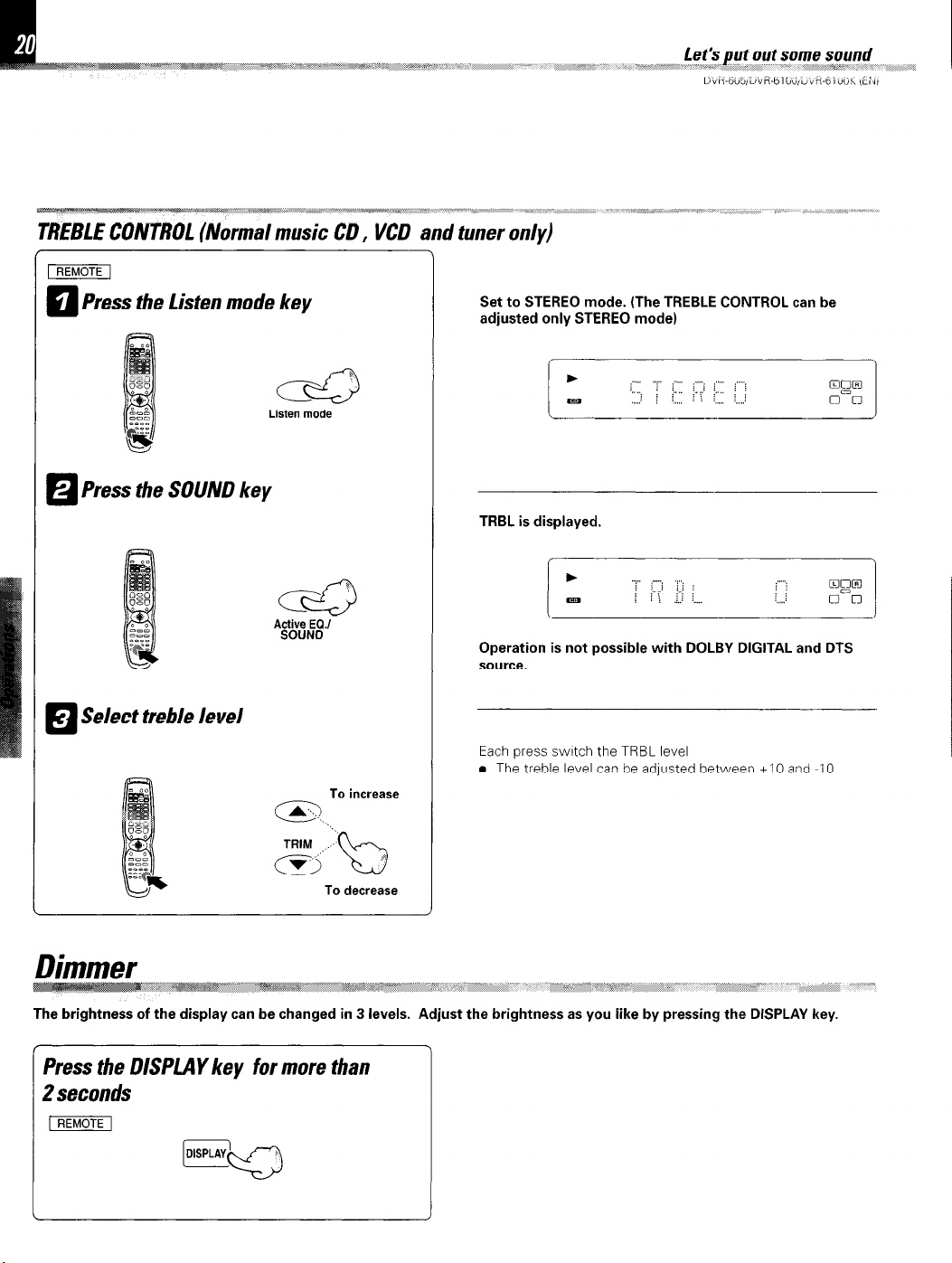
rREmF
Press the Listen mode key
q
Press the SOUND key
a
Select treble level
El
c&
Listen mode
To increase
Set to STEREO mode. (The TREBLE CONTROL can be
adjusted only STEREO mode)
TRBL is displayed.
Operation is not possible with DOLBY DIGITAL and DTS
source.
Each press switch the TRBL level
l
The treble level can be adjusted between +I 0 and -10
To decrease
Dimmer
The brightness of the display can be changed in 3 levels.
Press the DISPLAY key for more than
2 seconds
[rizix%F
.~~~.-.
**j
#N,&sF ,,-““““““~~~~~~~~~=~ ,_
,* .; /‘
_ _ . ..*.*,,* -/, ~~“a :-yii,><*: _ L _‘
.\
Adjust the brightness as you iike by pressing the DISPLAY key.
,, ,,/,/
Page 21
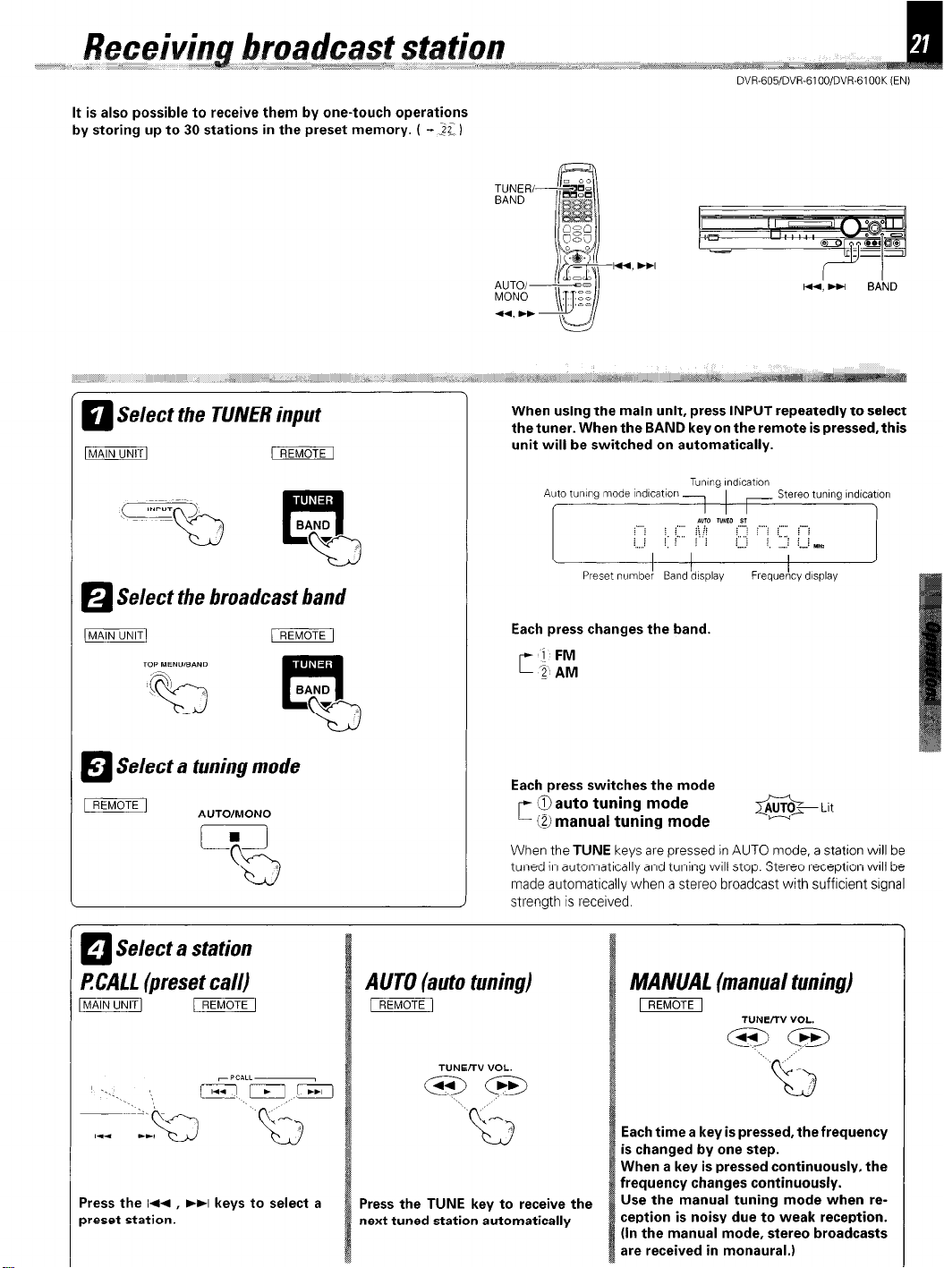
It is also possible to receive them by one-touch operations
by storing up to 30 stations in the preset memory. ( - 22 1
TUNER/BAND
AUTOIMONO
DVR-605/DVR-6100/DVR-6100K (EN)
Select the TUNER input
a
Select the broadcast band
Select a tuning mode
VJ
AUTOIMONO
i=i
b
i
When using the main unit, press INPUT repeatedly to select
the tuner. When the BAND key on the remote is pressed, this
unit will be switched on automatically.
Each press changes the band.
[I ‘;~ ;“M
Each press switches the mode
c 0 auto tuning mode
0 manual tuning mode
When the TUNE keys are pressed in AUTO mode, a station will be
tuned in automatically and tuning will stop. Stereo reception will be
made automatlcally when a stereo broadcast with sufficient slgnal
strength is received
i
AUTO- Lit
0
1 Select a station
0
RCALL (preset call)
Press the 144 , )+I keys to select a
preset station.
AUTO (auto tuning)
-1
TUNE/TV VOL.
@lm
Press the TUNE key to receive the
next tuned station automatically
MANUAL (manual tuning)
pEmF
TUNE/TV VOL.
+z3
Each time a key is pressed, the frequency
is changed by one step.
When a key is pressed continuously, the
frequency changes continuously.
Use the manual tuning mode when reception is noisy due to weak reception.
(In the manual mode, stereo broadcasts
are received in monaural.)
./’
Page 22
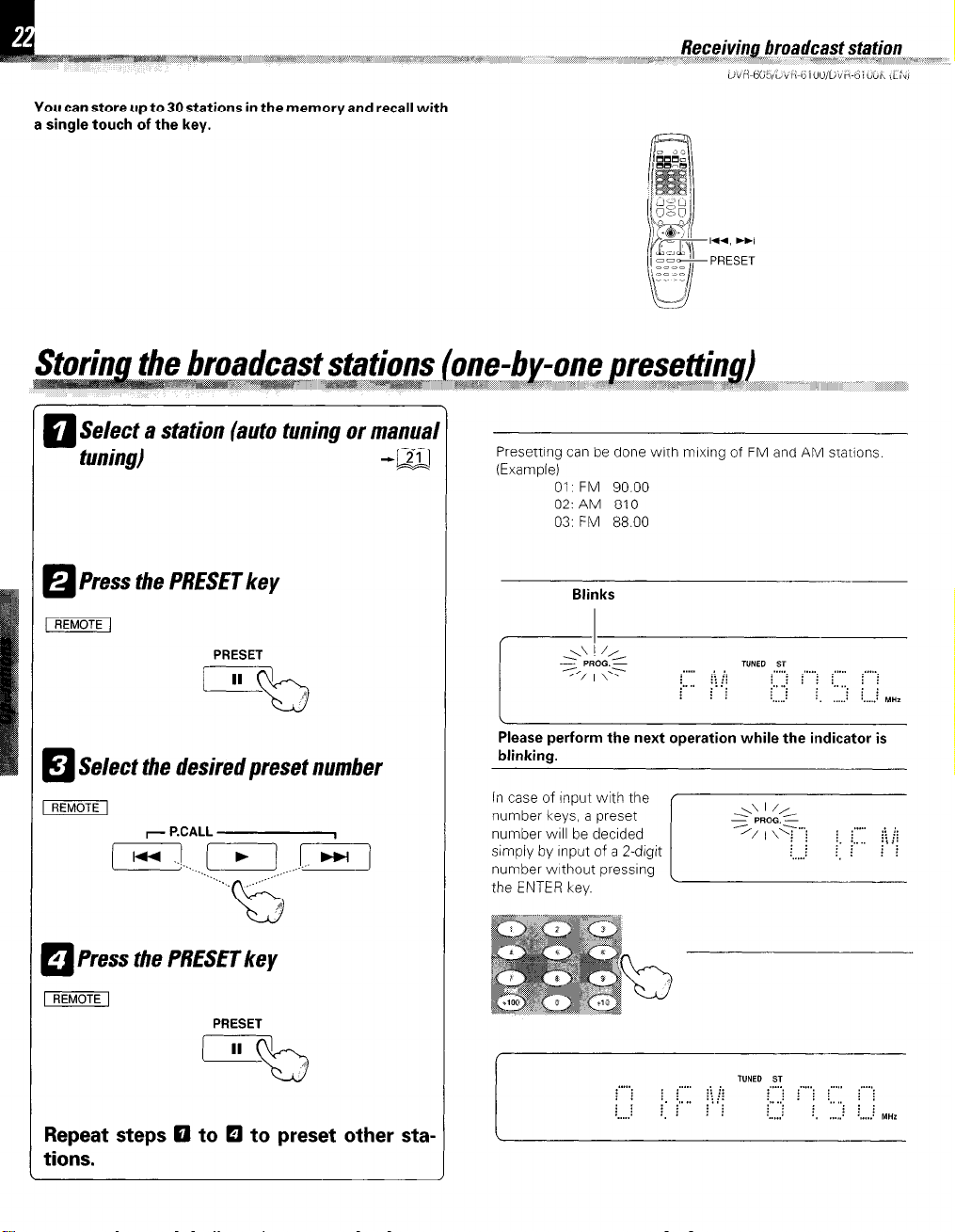
You can store up to 30 stations in the memory and recall with
a single touch of the key.
Select a station (auto tuning or manual
q
tuning)
Press the PRESET key
q
-a
I-
PRESET
Presetting can be done with mlxlng of FM and AM statlons
(Example)
01 FM 90.00
02: AM 810
03: FM 88.00
Blinks
Select the desired preset number
!a
REMOTE1
7 P.CALL
1 Press the PRESET key
q
PRESET
Repeat steps El to El to preset other sta-
tions.
f
Please perform the next operation while the indicator is
blinking.
in case of input with the
number keys, a preset
number WIII be decided
Page 23
d *
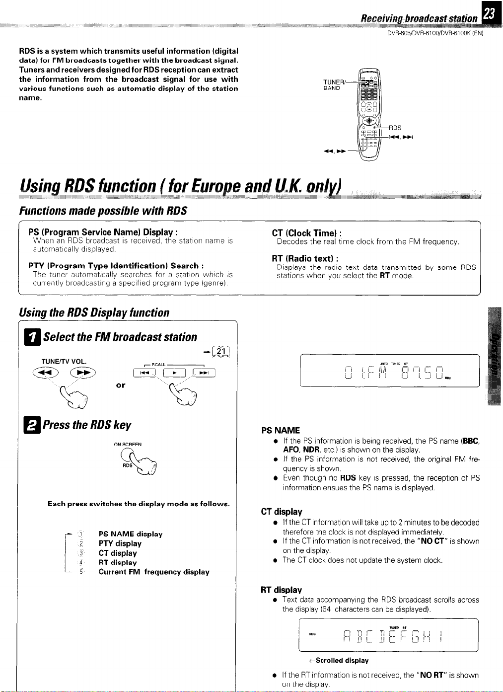
RDS is a system which transmits useful information (digital
data1 for FM broadcasts together with the broadcast signal.
Tuners and receivers designed for RDS reception can extract
the information from the broadcast signal for use with
various functions such as automatic display of the station
name.
Functions made possible with RDS
, ,&in‘ ,,,,,, > ,:. .,-‘&x*,*
-7&s;>‘. atom,,,,“.
TUNER/
BAND
Reb:
DVR-605/DVR-6100/DVR-6100K (EN)
RDS
PS (Program Service Name) Display :
When an RDS broadcast IS received, the statlon name IS
automatlcally dlsplayed.
PTY (Program Type Identification) Search :
The tuner automatlcally searches for a statlon which IS
currently broadcastlng a speclfled program type (genre).
Usina the RDS Disolav function
Select the FM broadcast station
El
Press the RDS key
H
, I
ON SCREEN
c
RDS
”
b
Each press switches the display mode as follows.
PS NAME display
1
i
PTY display
3‘
CT display
‘7
RT display
5
Current FM frequency display
--
CT (Clock Time) :
Decodes the real time clock from the FM frequency
RT (Radio text) :
Displavs the radio text data transmitted bv some RDS
staiio& when you select the
PS NAME
l
If the PS information
AFO, NDR,
l
If the PS information is not received, the original FM fre-
quency
l
Even though no
information ensues the PS name
CT display
l
If the CT information WIII take up to 2 minutes to be decoded
therefore the clock is not displayed immediately.
l
If the CT information is not received, the “NO
on the display.
l
The CT clock does not update the system clock.
etc.) is shown on the display.
IS
shown.
RDS
RT
mode
IS
being received, the PS name
key is pressed, the reception of PS
IS
displayed.
CT”
(BBC,
is shown
RT display
l
Text data accompanying the RDS broadcast scrolls across
the display (64 characters can be displayed).
tScrolled display
l
If the RT information
on the display.
IS
not received, the “NO
RT”
is shown
Page 24

and U.K. only)
,~,,~,,,,,,~~~~~‘~,,,“‘~ 1V<#@asS “r
The PTY information is composed of an identification symbol, which helps the FM radio to recognize the program type
of each FM station.
The 29 PTY modes are shown in the display by pressing
the PTY key.
Using the PTYsearch function
Select the FM band
q
Press the PTY key
El
TUNERIBAND
RDS Program types
PTY
l
The PTY MODE (POP M, ROCK M etc.) ap
pears on the display.
Press the RCALL M+bbi) keys to se.
lect the desired program ty-pe.
T P.CALL
1 When the program type is selected
L3
,
press the PTY key.
Auto-search the station sequentially
l
Press again during search to cancel.
1 PTY not found 1
After display of NO PTY, return is made to the nor-
mal display.
Program Type Name
News
Current Affairs
Information
Scort
Education
Drama
Culture
Science
Varied
Pop Music
Rock Music
Easy Listening Music
Light Classical Music
Serious Classical Music
Other Music
Weather
Finance
Children’s programs
Social affairs
Religion
Phone in
Travel
Leisure
Jazz Music
Country Music
National Music
Oldies Music
_. .~ --
Folk Music
Documentary
. -
Receiver Display
NEWS
AFFAIRS
INFO
SPORT
EDUCATE
DRAMA
CULTURE
SCIENCE
VARIED
POP M
ROCK M
EASY M
LIGHT M
CLASSICS
OTHER M
WEATHER
FINANCE
CHILDREN
SOCIAL
RELIGION
PHONE IN
TRAVEL
LEISURE
JAZZ
COUNTRY
NATION M
OLDIES
FOLK M
DOCUMENT
Page 25

,,,,_
If your TV has a progressive scan feature, the progressive scan function allows you to enjoy higher quality
video signals when you play back DVD (etc.) software
from this unit.
DVR-605/DVR-6100/DVR-61OOK (ENI
ON SCREEN
ON SCREEN
Press and hold the ON SCREEN key for more
than 5 seconds
PROGRESSIVE ON scrolls in the display.
Each time you switch to the DVD/CD input “PROGRESSIVE
ON” scrolls in the display.
To turn off the progressive scan
Repeat this operation.
l
PROGRESSIVE OFF scrolls in the display.
l
There is no display when you switch to the DVD/CD input.
Page 26

STOP
1 PLAY/PAUSE
Select the DVD CD
a
l
When a disc is set on the tray and DVDKD IS selected,
playback of the disc will be started automatically.
OPEN/CLOSE INPLh
OOpen the tray.
OPlace a disc.
@Close the tray.
l
When the
instead of the
close and playback will start automatically.
When a Disc Menu appears on the screen
In case of Interactive DVDs, a DISC Menu appears on the screen
ThenpressENTERtoselectspecif~cmenuyouwanttoplaybyuslng
Cursor keys.
menu screen will be displayed when the TOP MENU
selected by pressing the Cursor keys.
PLAY/PAUSE
OPEN/CLOSE
key on the main unrt is pressed
key in step 0, the tray will
TOP MENU
Label side
Start playback
5
l
Each press PLAY/PAUSE
key on the marn unrt
pauses and plays the disc
alternately.
To stop playback
l
Press II key on the remote
control unrt to pause the disc
PRESET
AUTO/MONO
. When the PLAY/PAUSE key on the main unit IS pressed whrle
an input other than drsc is selected, the unit will be swrtched to
DVD/CD and playback wrll start.
TRACK No. ICDI
CHAPiER No. WDI
TITLE No. IDVD)
Time display
1 RESUME playback
When the STOP key has been pressed once during
playback to stop the playback, and then playback is
started again, play will start from the point where
the playback had been stopped. This is called the
RESUME function. When the STOP key is pressed
again during stop, the RESUME function is cancelled.
RESUME is cancelled when 5 minutes have passed in
RESUME status.
1
Page 27

Disc playback features
~~~~sez,,,;“rr‘~~s=w~
Not%
a
l
You won’t hear the sound (audio) on the DVD
when you’re using the Skip, Search, Step or Slow
motion features.
o Playback features are not available during the
opening credits of a movie.
1.4, HI
STEP
@3GW&B SkimGn_a chapters or tracks
/MAlNUNIT/ pEmF
To skip
backward
(=-.. tQ
Id- D-1
l
The chapter (or track) in the direction of the key
. . 1 .
To skip
forward backward
-.__ ,
-.YIl
To skip To skip
rPc*LL
j, lry !?I
forward
../
..’
b
pressed is skipped, and the selected chapter (or track)
will be played from the beginning.
l
When the M key is pressed once during playback,
the chapter (or track) being played will be played from
the beginning.
@6&3B STEP (freeze frame and frame advance)
c \
I
DVR-605/6100 DVR-6100K
\
>a /_/I ,,,,,, ,,/ ,,,,,,, % ,‘S , ,,,,1.,,,,1 >__
SHIFT
STEP
a
+
I)
TI INF/T” vn,
.I.._.. .--.
-@3
i’.<
I
m@%B Slow motion playback
TUNE/TV VOL.
W@B Searching
m
To search
backward
l
During playback, press the M or H key
l
Each press switches the searching speed.
0 x 2 (F.SEARCH l)/(R.SEAFiCH 1)
@ x 4 (F.SEARCH 2MR.SEARCH 2)
@ x 8 (F.SEARCH 3MRSEARCH 3)
L
@ x 16 (F.SEARCH 4MRSEARCH 4)
l
Press the
playback.
l
Audio is not output during FSEARCH or RSEARCH
playback.
l
Select the desired track No.
l
Press the numeric kevs as shown below
(Example)
To select track No. 23 : m Bj
l
When a number exceedina the laraest track No. on
the CD being played is specified, a-question mark “Tr ?”
will be displayed.
_ i ,,-:,, _ ,,,, -,>,,- _ ,,,,,_ ,
l
Each time you press the M, - keys, the picture
advances one frame.
l
At the time of VCD playback, backward STEP is not
possible.
l
Press the
l
DVR61 OOK only
Press the SHIFT key before pressing the STEP key.
l
During playback, press the
M, H keys.
l
Each press M, w keys switches the motion speed.
(At the time of DVD playback)
0 F.SLOW l/16 (R.SLOW l/16)
@ F.SLOW l/8 (R.SLOW l/8)
@ F.SLOW l/4 (R.SLOW l/4)
L
@ F.SLOW l/2 (R.SLOW l/2)
(At the time of VCD playback)
0 F.SLOW l/8 (R.SLOW is not possible)
@ F.SLOW l/4 (R.SLOW is not possible)
L-
@ F.SLOW l/2
l
Press the
PLAY
PLAY
PLAY
T”NEnYYOL
00 To search
(At the time of DVD playback only)
key at any time to resume normal
,,. ,,,, ,,,, *,A,*,‘*. \\.,, ;> s#&” ,, _,,,,,_I Am
s
*
key to resume normal playback.
SLOW
keys, then press the
(RSLOW is not possible)
key to resume normal playback.
Page 28

The on-screen Banner Display contains many playback features. To see the Banner Display, press ON SCREEN (OSD)
while a disc is playing. Use the Cursor (Up/Down/Left/Right) keys to move through the different features in the
Banner Display. Each feature is illustrated with an icon.
0 During playback, press the ON SCREEN key.
When playing a DVD
CHAPTER SUBTITLES BOOKMARKS
TITLE
AUDIO
ANGLES
DISC TYPE
TIME INDICATOR
@Press the Cursor left/right (4)) keys to high-
light a banner display icon.
[MAIN
/
0 Press the ENTER key.
To display disappear from the screen
When playing a CD/VCD
INTROSCAN
TRACK
TIME INFORMATION
TIME INDICATOR
Switch the CD time indicator as follows.
0 Select the time information with the cursor key.
0 Each time the ENTER key is pressed, the time
indicator changes as follows.
@Track Elapsed
@Track Remain
(3 Disc Elapsed
@ Disc Remain
(elapsed time of the track being played)
(remaining time of the track being played)
(elapsed time of the disc being played)
VernalrIng tln?e of the disc being played)
Press the ON SCREEN (OSD).
l
You can only access the banner display when you’re
playing a disc.
l
The bannerdisplayfeatureareonlyavarlable if the disc was
created with that particular feature (i.e., if you select the
Subtitle icon, you won’t be able to change the subtitle
language unless the author of the disc created the disc wrth
subtitles).
l
The invalid symbol &I appears on the screen when you
press a key that doesn’t have any function. If one of the
icons is “grayed out,” the banner display feature isn’t
available for the disc you’re playing.
Page 29

DVR-605/DVR-61OO/DVRB1OOK (EN)
/ec
Some discs contain more than one title. For example,
there might be four movies on one disc (each movie
might be-considered a title).
0 During playback, press the ON SCREEN key.
0 Press the Cursor left/right (4)) keys until the
TITLE icon is highlighted.
IUNIT/
~~~~
~~,~*:,,.~,~~~:~~~.~~~~~~ * _
.,.
IREMOTEl
~C;. ,*n,,
Because DVD discs use digital technology, a title can
be divided into individual chapters (similar to tracks on
a CD). You can skip a specific chapter by using the
Chapter section in the Banner Display.
@During playback, press the ON SCREEN key.
@Press the Cursor left/right (d/b) keys until the
CHAPTER or TRACK icon is highlighted.
piViiGM
IREMOTEl
0 Press the ENTER key.
(“T-” appears)
/I IREMOTEl
0 Use the numeric keys on the remote or the cursor
keys on the main unit to enter the title number.
iNhen you enter a one-digit Title number, you may
iave to press ENTER on the remote after pressing
the numeric key (I-9) on the remote. Otherwise
press 0 first and the other value. Then play starts.
This varies depending on number of Title within the
disc you’re playing.
@Press the ENTER key.
(“C-” or “Tr-” appears)
[p&KUiWj IREMOTEl
Q Use the numeric keys on the remote, or the skip
keys on the main unit to enter the chapter or track.
piMTEi7
When you enter a one-digit chapter or track number,
you may have to press ENTER on the remote after
pressing the numeric key (I-9) on the remote. Otherwise press 0 first and the other value. Then play
starts. This varies depending on number of chapter
or track within the disc you’re playing.
-1
Some discs only have one title.
Not?5
a
l
The Chapter feature won’t work if the disc isn’t
formatted with separate chapters.
l
P.B.C. on mode of VCD, the Selecting a Track
function may not work.
Page 30

If the disc was created with different language tracks,
you can use the Banner Display to temporarily change
the DVD player’s Audio setting.
You can change the Subtitle language while you’re
watching a disc (but only if the disc was created with
subtitles).
Using the on-screen banner display
0 During playback, press the ON SCREEN key.
OPress the Cursor left/right (4/b) keys until the
AUDIO icon is highlighted.
piiiimm
0 Press the ENTER key.
piiiinm rEEfma
The audio menu appears
pimF
Using the on-screen banner display
0 During playback, press the ON SCREEN key.
pi?imm rmmc
ON SCREEN
\p
cl
@Press the Cursor left/right (r/b) keys until the
SUBTITLE icon is highlighted.
pciLimr /I
0 Press the ENTER key.
piiciEm rEEimq
ON SCREEN
c
b
Displayed whel
SUBTITLE is 01
@ Press the ENTER key repeatedly to select the
audio language.
piiiizm
l
The menu is switched off when no operation is
performed for about 5 seconds.
1. The language feature only works If the drsc was created
with multiple audio tracks
2. When you chose an audro language from the Banner Drsplay, you only override the audio language settrng rn the
DVD Player’s marn menu (in the Language Preferences
menu within Setup menu) temporarily.
ri?azF
9 Select the subtitle language with press the EN-
TER key.
p2GmiTy (1
0 Press the S.TITLE key to turn subtitles ON or OFF.
I Remote control unrt only1 S.T,TLE
,
o The menu is switched off when no operation is
performed for about 5 seconds.
1 The subtitle feature only works if the dtsc was createc
wrth multtple subtItle tracks
2 The subtltle menu of the disc appears rn sorme drscs
[ l
REC ’
4
b
Page 31

Page 32

Page 33

Page 34

Page 35

Page 36

Page 37

Page 38

Page 39

Page 40

Page 41

Page 42

Page 43

Page 44

Page 45

Page 46

Page 47

Page 48

Page 49

Page 50

Page 51

Page 52

Page 53

Page 54

Page 55

Page 56

Page 57

Page 58

Page 59

Page 60

Page 61

Page 62

Page 63

Page 64

Page 65

Page 66

Page 67

Page 68

Page 69

Page 70

Page 71

Page 72

Page 73

Balancing the Speakers
Place the surround
speakers as high 8s
,ms,ble, directly to the
sides of the listening area,
pomting at the listeners
000000
LEFT
FRONT FRONT
RlOHT CENTER Lwr RIGHT sue-
S"RRO"N0 SURROUND WOOFER
Page 74

I -
Page 75

TO get the best video quality from all your video sources, use the chart below to determine
what connections you need to make between the DVD receiver and your TV:
MAKE THESE CONNECTIONS
FROM DVD RECEIVER TO TV
Note: Since the Component Video output only funcfmns wth the DVD recwver’s buikrn DVD
player, If you have connected any other video components to the DVD receiver you will also
need to connect the DVD receiver to the TV using the same type(s) of connect!ons used for the
connected components.
DVR-
Page 76

(Speaker Quick-Connect Guide on other side)
TO TO
WOE0 WOE0
PLAY RECORD
OVT IN
tt
DVR-606 DVD RECEIVER
DSSREIIEIVER + +
CABLE TUNER
TO AVOlO OVT
ii
TV or MONITOR
TO 0IeITALO”T
se contact our Customer Service Department at (800) KENWOOD, or visit our Web site at www.kenwoodusa.com
 Loading...