

Kenwood DVK-750, DVS-700 Service manual
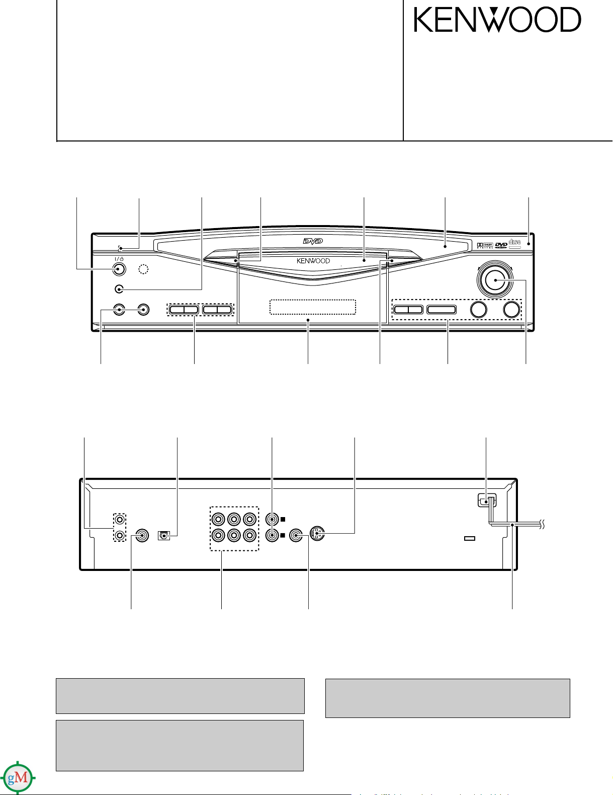
L
R
FRONT
SURROUND
CENTER
SUB
WOOFER
MIX LINE
OUTPUT
VIDEO
OUTPUT
COAXIAL
SYSTEM
CONTROL
OPTICAL
7 3
¢4
¡1
MIC 2MIC 1
POWER
- ON – OFF
ON / STANDBY
DVD/VCD/CD PLAYER DV-K750
SHUTTLE
0
w∑ 8
/
D.R.I.V.E.
DIGITAL AUDIODIGITAL AUDIO
COMPACTCOMPACT
TEXTTEXT
FL
DISPLAY
CD/VIDEO-CD/DVD PLAYER
DV-K750/S700
SERVICE MANUAL
© 1997-12/B51-5400-00 (K/K) 3207
Knob
(K29-6835-12)
Phone jack
(E11-0366-05)
Miniature phone jack
(E11-0188-05)
Indicator
(B12-0311-04)
Oscillating module
(W02-1114-05)
Knob
(K27-2449-04)
Knob
(K29-6835-12)
Dressing panel *
(A21-)
Front glass
(B10-2386-12)
Phono jack
(E63-0068-15)
Dressing panel *
(A21-)
Dressing panel *
(A21-)
Cylindrical receptacle
(E56-0014-05)
Dressing panel
(A21-3627-12)
Knob
(K29-6835-12)
Power cord bushing
(J42-0083-05)
Panel *
(A60-)
Knob
(K29-6945-04)
Phono jack *
(E63-)
Phono jack
(E63-0199-05)
In compliance with Federal Regulations, following are
reproductions of labels on, or inside the product relating to laser
product safety.
KENWOOD-Crop. certifies this equipment conforms to DHHS
Regulations No. 21 DFR 1040. 10, Chapter 1, Subchapter J.
DANGER : Laser radiation when open and interlock defeated.
AVOID DIRECT EXPOSURE TO BEAM
Phono jack
(E63-0130-08)
Caution : No connection of ground line if disassemble the
NOTE : Please replace the mechanism PCB
AC power cord *
(E30-)
* Refer to parts list on page 36.
unit. Please connect the ground line on rear
panel, PCBs, Chassis and some others.
(W02-2626-05) with new one, if it is
malfunction.
DV-K750/S700
Note related to transportation and movement
Before transporting or moving this unit, carry out the following
operations.
1. Turn the unit ON but do not load a disc.
2. Verify that the display shown appears.
3. Wait a few seconds and set the unit to STANDBY mode.
Beware of condensation
When the difference between the internal temperature of the unit
and external atmosphere is large, dew (mist) may be produced on the
internal parts of the unit. In such a case, turn the unit ON and leave
it for a few hours until the condensation has dried up.
Be especially careful in the following conditions:
When the unit is brought into a place where there is a large difference
in temperature between the previous location, when the humidity of
the listening room is high, etc.
Operation to reset
The microcomputer may fall into malfunction (impossibility to operate, erroneous display, etc.) when the connection cords are unplugged while unit is ON or due to an
external factor. In this case, execute the following method
to reset the microcomputer and return it to normal condition.
While holding the stop (7) key depressed, press the
POWER switch to OFF then ON again.
÷ Please be aware that resetting this unit will erase all stored informa-
tion and return it to the factory settings.
CONTENTS/ACCESSORIES/CAUTIONS
CONTENTS
CONTENTS/ACCESSORIES/CAUTIONS...................2
CONTROLS.................................................................3
DISASSEMBLY FOR REPAIR.....................................5
BLOCK DIAGRAM.......................................................9
CIRCUIT DESCRIPTION...........................................12
ADJUSTMENT...........................................................19
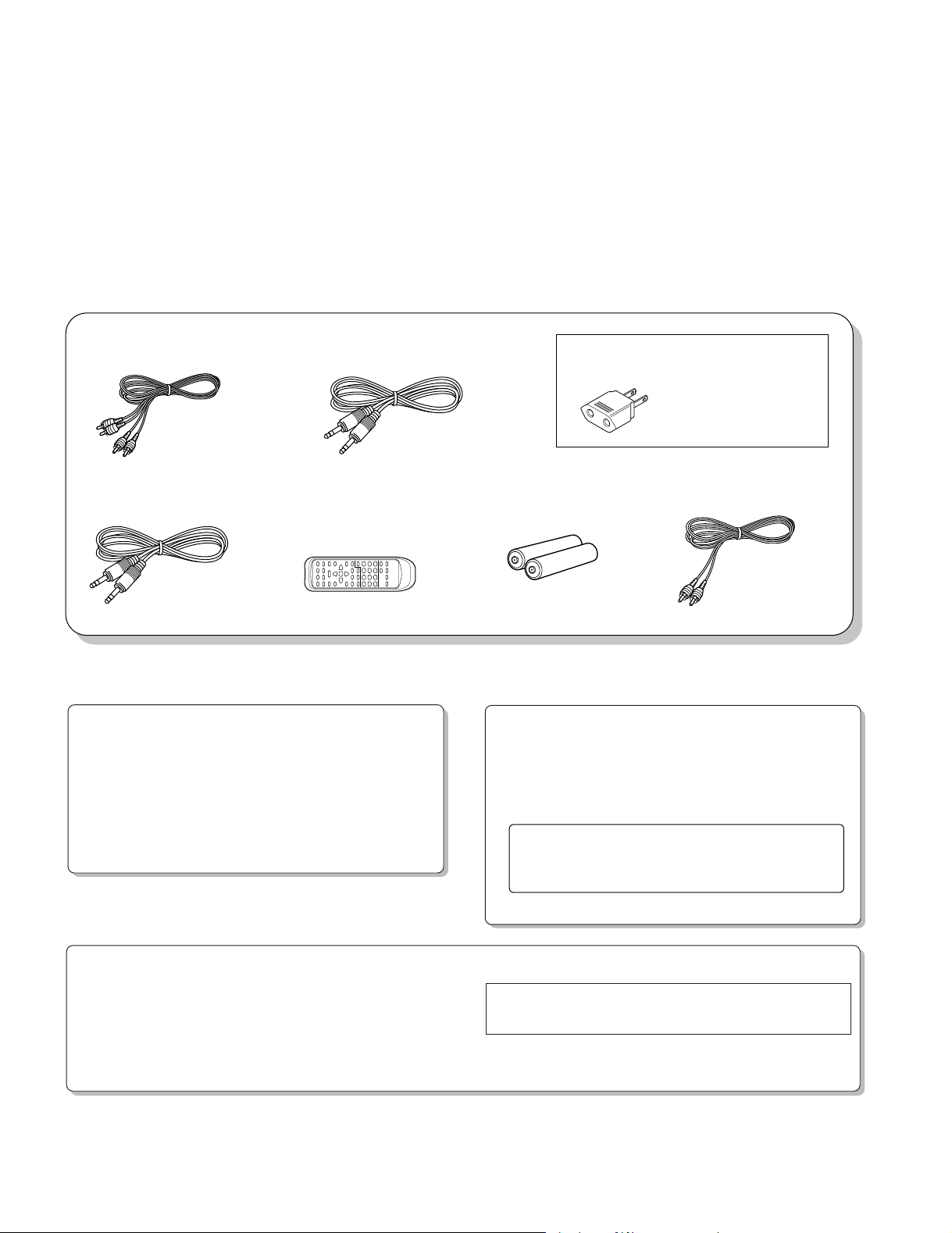
Accessories
PARTS DESCRIPTION..............................................20
PC BOARD ............................................................... 21
SCHEMATIC DIAGRAM........................................... 23
EXPLODED VIEW .....................................................33
PARTS LIST...............................................................36
SPECIFICATIONS.....................................................45
Audio cord (Red, White).....(1)
(E30-0505-05)
System control cord............(2)
(E30-2733-05)
Cautions
Digital cord (Orange)..........(1)
(E30-2365-05)
Remote control unit ............(1)
RC-D0701 : A70-1192-05
RC-D0702 : A70-1193-05
RC-D0700 : A70-1198-05
battery cover : A09-0362-08
AC plug adapter................. (1)
(E03-0115-05)
Batteries (R6/AA)................(2)
(–)
Use to adapt the plug on
the power cord to the shape
of the wall outlet.
(Accessory only for regions
where use is necessary.)
Video cord (Yellow) ............(1)
(E30-1427-05)
2
N O D I S C
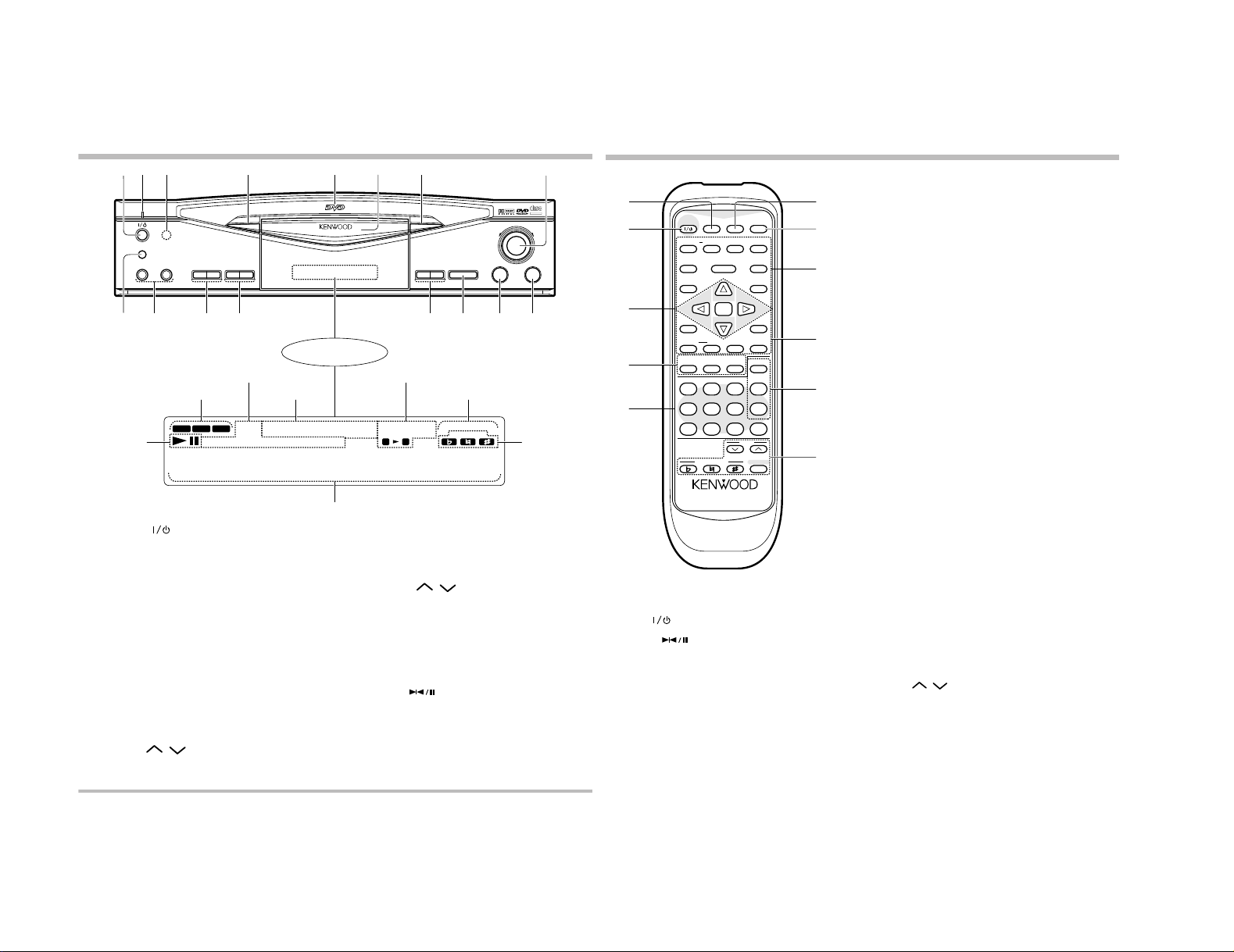
32 4 5 7
Main unit keys with the same names as the keys on the
remote control unit have the same functions as them.
Main unit (DV-K750)
Display
Character information display
Play and pause
indicators
DVD, VCD and CD indicators
VCD and CD information indicators
DVD information
indicators
Special playback indicators
L, STEREO and R indicators
1ON/STANDBY ( ) key
Press to turn power of the unit from on to standby or vice versa.
2 Standby indicator
Lights in power standby mode and goes off in power on mode.
3Remote sensor
4FL DISPLAY key
Press to switch the displayed information contents.
5DVD indicator
Lights when a DVD disc is played.
6Disc tray
Place the disc to be played on the tray.
7Open/close (0) key
Press to open or close the disc tray.
(When the unit is connected to another component through a system
cord and is in standby mode, pressing this key automatically turns the
unit on and opens the disc tray.)
8SHUTTLE (1, ¡) control
Press to fast forward or reverse a track or chapter.
9POWER switch
Press to turn the power of the unit between the standby and off
modes.
0MIC 1 and MIC 2 jacks (DV-K750 only)
Connect microphones to these jacks.
!MIC 1 LEVEL ( , ) controls (DV-K750 only)
Press to adjust the microphone 1 volume.
Karaoke operation
indicators (DV-K750
only)
TEXT DISPLAY key (DV-S700 only)
During playback of a CD-TEXT disc, press to switch the character
information display.
ALL INFO. key (DV-S700 only)
During playback of a CD-TEXT disc, press to display all character
information available.
@MIC 2 LEVEL ( , ) controls (DV-K750 only)
Press to adjust the microphone 2 volume.
TITLE SEARCH key (DV-S750 only)
During playback of a CD-TEXT disc, press to switch title search on and
off.
REPEAT key (DV-S700 only)
Press for repeated playback.
#Skip (4, ¢) keys
DVD or VCD: Press either key to skip chapters or locate the begin-
ning of a chapter
CD: Press to skip tracks or locate the beginning of a track.
$Still/pause ( ) key
DVD or VCD: Press during playback to freeze the video or press
during pause to advance the video frame by frame.
CD: Press to let playback pause temporarily.
%Stop (7) key
^Play (3) key
Press to play audio and video.
(When the unit is connected to another component through a system
cord and is in standby mode, pressing this key automatically turns the
unit on and starts playback.)
About the STANDBY mode
While the STANDBY indicator is lit, a small amount of power is supplied to the system to back up the memory. This is called the standby mode. Under
that condition, the system can be turned ON by the remote control unit.
Remote control unit
1FL DISPLAY key
2POWER (
) key
3CD, VCD and DVD operation keys
Still/pause ( ) and up (%) key
Press to move the cursor upward or let playback pause temporarily.
During VCD or DVD playback, this key is also used to freeze the video
and advance it frame by frame.
ENTER key
Press to input the item selected with the cursor. This key is also used to
start playback of the track, chapter or title selected with the numeric keys.
Fast forward (¡), fast reverse (1), SLOW and left/right (@, #) keys
Press either key to move the cursor to the left or right or to play a disc
at a high speed in the forward or reverse direction. During VCD or DVD
playback, these keys are also used in slow playback.
Down (fi) key
Press to move the cursor downward.
4CD-TEXT operation keys
TEXT DISPLAY key (CD)
When a CD-TEXT disc is used, press to switch the character information display.
ALL INFO key (CD)
When a CD-TEXT disc is used, press to display all character information.
TITLE SEARCH key (CD)
When a CD-TEXT disc is used, press to switch the title search mode
on and off.
The remote control keys with the same names as the keys on
the main unit have the same functions as them.
5Numeric (0 to 9) keys
Press for direct input of track and chapter numbers. When a CD or VCD
disc is used, press to input the track number to be searched by track
search. When a DVD disc is used, press to input the figures for title
search, chapter search or time search.
6STEREO key (DVD)
When a DVD disc is used, press to switch the surround setup on and off.
7OPEN/CLOSE (0) key
8TV monitor operation keys
SUBTITLE key (DVD)
During playback of a DVD disc, press to display the subtitle language
code on the TV screen.
SUBTITLE ON/OFF key (DVD)
During playback of a DVD disc, press to switch the subtitle on and off.
AUDIO key (VCD, DVD)
During playback of a VCD disc, press to display the voice language
code on the TV screen. During playback of a DVD disc, press to switch
the audio between STEREO, L and R.
ANGLE key (DVD)
During playback of a DVD disc, press to display the angle number on
the TV screen.
ON SCREEN key (CD, VCD, DVD)
Press to switch the search picture display on the TV screen on and off.
RETURN key (VCD, DVD)
Press to return to the previous menu.
SETUP key (DVD)
Press to display the initial setting screen.
TITLE key (DVD)
Press to display the title menu recorded in the DVD disc.
MENU key (DVD)
Press to display the DVD menu recorded in the DVD disc.
9CD, VCD and DVD operation keys
PREV. (4) and NEXT (¢) keys
Press to skip tracks or locate the beginning of a track. When a VCD or
DVD disc is used, press to select the P.B.C., skip chapters or locate
the beginning of a chapter.
REPEAT key
Press to switch repeated playback on and off.
REPEAT A-B key
Used in A-B repeated playback.
Stop (7) key
SELECT/play (3 ) key
Press to start playback. When a VCD disc is used, press to select a
menu in the PBC mode.
0Program operation keys
CLEAR key (CD, VCD, DVD)
Press in the program mode to clear the last track or chapter in the
program. In the memory mode, press to clear the selected memory
number. During numeric input, press to clear the input figures.
MEMORY key (DVD)
Press to store in memory a scene that you want to see later again.
P.MODE key (CD, VCD)
Press when programming tracks in the desired order.
!Karaoke operation keys (DV-K750 only)
ECHO (
, ) keys
Press to adjust the echo effect in the karaoke mode.
Flat (I) key
Press to lower the key of the music in the karaoke mode.
Natural (È) key
Press to return the key of the music to the original key (0) in the
karaoke mode.
Sharp (i) key
Press to higher the key of the music in the karaoke mode.
KARAOKE key
Press to switch the karaoke mode on and off.
1
6
8
ON / STANDBY
POWER
- ON – OFF
MIC 2MIC 1
D.R.I.V.E.
9
0 ! @ # $ % ^
DVD VCD CD
FL
DISPLAY
P.B.C. DOLBY DIGITAL RANDOM PROG.
TITLE CHAPTER TRACK CD TEXT
•••••••••••••••
3
A B
0
¢4
L R
/
w∑
8
STEREO
KARAOKE
DVD/VCD/CD PLAYER DV-K750
ANGLE REPEAT ALL
1
7 3
SHUTTLE
COMPACTCOMPACT
DIGITAL AUDIODIGITAL AUDIO
TEXTTEXT
¡
1
2
3
4
5
RC-D0702
POWER
FL DISPLAY
STEREO
OPEN/CLOSE
SUBTITLE ON/OFF AUDIO ANGLE
ON SCREEN
TITLE MENU
SLOW
1
PREV. NEXT
4
REPEAT A-B SELECT
TEXT
DISPLAY
1 2 3
4 5 6
7 8 9 0
KEY CONTROL
REMOTE CONTROL UNIT
SETUP
RETURN
/
8
w∑
SLOW
ENTER
ALL
TITLE
INFO.
SEARCH
CLEAR
MEMORY
P.MODE
ECHO
KARAOKE
0
¡
¢
37
6
7
8
9
0
CONTROLS
!
DV-K750/S700
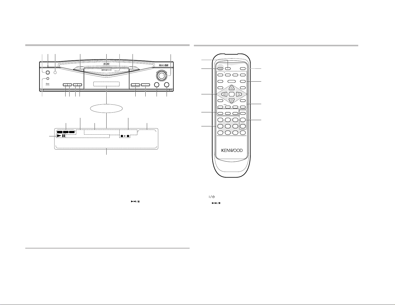
Main unit keys with the same names as the keys on the
remote control unit have the same functions as them.
Main unit (DV-S700)
Display
Character information display
Play and pause
indicators
DVD, VCD and CD indicators
VCD and CD information indicators
DVD information
indicators
Special playback indicators
L, STEREO and R indicators
1REMOTE POWER key
Press to turn power of the unit from on to standby or vice versa.
2 Standby indicator
Lights in power standby mode and goes off in power on mode.
3Remote sensor
4FL DISPLAY key
Press to switch the displayed information contents.
5DVD indicator
Lights when a DVD disc is played.
6Disc tray
Place the disc to be played on the tray.
7Open/close (0) key
Press to open or close the disc tray.
(When the unit is connected to another component through a system
cord and is in standby mode, pressing this key automatically turns the
unit on and opens the disc tray.)
8SHUTTLE (1, ¡) control
Press to fast forward or reverse a track or chapter.
9MAIN POWER switch
Press to turn the power of the unit between the standby and off
modes.
0TEXT DISPLAY key
During playback of a CD-TEXT disc, press to switch the character
information display.
!ALL INFO. key
During playback of a CD-TEXT disc, press to display all character
information available.
@TITLE SEARCH key
During playback of a CD-TEXT disc, press to switch title search on and
off.
#REPEAT key
Press for repeated playback.
$Skip (4, ¢) keys
DVD or VCD: Press either key to skip chapters or locate the begin-
ning of a chapter
CD: Press to skip tracks or locate the beginning of a track.
%Still/pause ( ) key
DVD or VCD: Press during playback to freeze the video or press
during pause to advance the video frame by frame.
CD: Press to let playback pause temporarily.
^Stop (7) key
&Play (3) key
Press to play audio and video.
(When the unit is connected to another component through a system
cord and is in standby mode, pressing this key automatically turns the
unit on and starts playback.)
About the STANDBY mode
While the STANDBY indicator is lit, a small amount of power is supplied to the system to back up the memory. This is called the standby mode. Under
that condition, the system can be turned ON by the remote control unit.
4
Remote control unit
1FL DISPLAY key
2POWER (
) key
3CD, VCD and DVD operation keys
Still/pause ( ) and up (%) key
Press to move the cursor upward or let playback pause temporarily.
During VCD or DVD playback, this key is also used to freeze the video
and advance it frame by frame.
ENTER key
Press to input the item selected with the cursor. This key is also used
to start playback of the track, chapter or title selected with the numeric
keys.
Fast forward (¡), fast reverse (1), SLOW and left/right (@, #)
keys
Press either key to move the cursor to the left or right or to play a disc
at a high speed in the forward or reverse direction. During VCD or DVD
playback, these keys are also used in slow playback.
Down (fi) key
Press to move the cursor downward.
The remote control keys with the same names as the keys on
the main unit have the same functions as them.
4CD-TEXT operation keys
TEXT DISPLAY key (CD)
When a CD-TEXT disc is used, press to switch the character information display.
ALL INFO key (CD)
When a CD-TEXT disc is used, press to display all character information.
TITLE SEARCH key (CD)
When a CD-TEXT disc is used, press to switch the title search mode
on and off.
5Numeric (0 to 9) keys
Press for direct input of track and chapter numbers. When a CD or VCD
disc is used, press to input the track number to be searched by track
search. When a DVD disc is used, press to input the figures for title
search, chapter search or time search.
6OPEN/CLOSE (0) key
7TV monitor operation keys
SUBTITLE key (DVD)
During playback of a DVD disc, press to display the subtitle language
code on the TV screen.
SUBTITLE ON/OFF key (DVD)
During playback of a DVD disc, press to switch the subtitle on and off.
AUDIO key (VCD, DVD)
During playback of a VCD disc, press to display the voice language
code on the TV screen. During playback of a DVD disc, press to switch
the audio between STEREO, L and R.
ANGLE key (DVD)
During playback of a DVD disc, press to display the angle number on
the TV screen.
ON SCREEN key (CD, VCD, DVD)
Press to switch the search picture display on the TV screen on and off.
RETURN key (VCD, DVD)
Press to return to the previous menu.
SETUP key (DVD)
Press to display the initial setting screen.
TITLE key (DVD)
Press to display the title menu recorded in the DVD disc.
MENU key (DVD)
Press to display the DVD menu recorded in the DVD disc.
8CD, VCD and DVD operation keys
PREV. (4) and NEXT (¢) keys
Press to skip tracks or locate the beginning of a track. When a VCD or
DVD disc is used, press to select the P.B.C., skip chapters or locate
the beginning of a chapter.
REPEAT key
Press to switch repeated playback on and off.
REPEAT A-B key
Used in A-B repeated playback.
Stop (7) key
SELECT/play (3 ) key
Press to start playback. When a VCD disc is used, press to select a
menu in the PBC mode.
9Program operation keys
CLEAR key (CD, VCD, DVD)
Press in the program mode to clear the last track or chapter in the
program. In the memory mode, press to clear the selected memory
number. During numeric input, press to clear the input figures.
MEMORY key (DVD)
Press to store in memory a scene that you want to see later again.
P.MODE key (CD, VCD)
Press when programming tracks in the desired order.
DV-K750/S700
32 4 5 7
1
REMOTE POWER
ON / STANDBY
MAIN POWER
- ON – OFF
COMPACTCOMPACT
DIGITAL AUDIODIGITAL AUDIO
D.R.I.V.E.
TEXTTEXT
9
TEXT
DISPLAY
0 ! @ # $ % ^ &
DVD VCD CD
TITLE CHAPTER TRACK CD TEXT
•••••••••••••••
DISPLAY
ALL
TITLE
INFO.
SEARCHREPEAT
P.B.C. DOLBYDIGITAL RANDOM PROG.
DVD/VCD/CD PLAYER DV-S700
FL
6
/
w∑
8
STEREO
1
7 3
0
ANGLE REPEAT ALL
A B
¢4
L R
SHUTTLE
8
1
¡
2
3
4
5
RC-D0701
POWER
FL DISPLAY
OPEN/CLOSE
SUBTITLE ON/OFF AUDIO ANGLE
ON SCREEN
TITLE MENU
SLOW
1
PREV. NEXT
4
REPEAT A-B SELECT
TEXT
DISPLAY
1 2 3
4 5 6
SETUP
RETURN
/
8
w∑
SLOW
ENTER
ALL
TITLE
INFO.
SEARCH
CLEAR
MEMORY
P.MODE
7 8 9 0
REMOTE CONTROL UNIT
0
6
7
¡
¢
37
8
9
CONTROLS
DISASSEMBLY FOR REPAIR
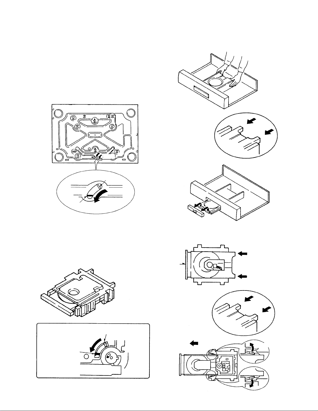
How to Disassemble
1. The disc is not coming out by pressing the open botton.
1. Remove the case and DVD disc in the unit.
2. Insert the small screw driver into the hole on
the bottom chassis.
3. Travel the rotary cam to the tray open position.
4. Travel the tray to open position by hand.
5. Remove the dress panel.
OPEN
DV-K750/S700
CLOSE
OPEN
2. The Loading Tray
1. Travel the rotary cam to the tray open position.
2. Travel the tray to open position by hand.
3. Open the hooks of the tray holder and pull out it.
TRAY
CLOSE
PUSH
TRAY
TRAY
OPEN
OPEN
5
DV-K750/S700
DISASSEMBLY FOR REPAIR
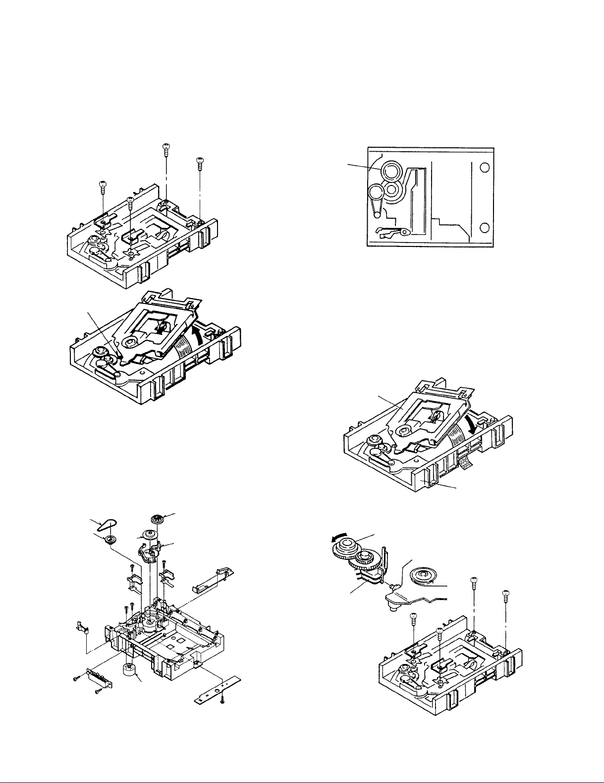
3. Traverse Unit
1. Remove the screws fixing the plate spring, the chassis
stopper and the spring.
2. Lift the back of the traverse unit and remove it.
CONNECTING
POINT
How to Assemble
1. Loading Mechanism
This mechanism has no order for assembling the
loading parts.
TRAY GEAR
2. Traverse Unit
1. Pass the flexible cable from the inside of the loading
base to the outside of that.
2. Insert the top of the traverse unit to the groove of the
rotary cam and fix it with screws.
4. Loading Mechanism Parts
1.The loading parts is avalable without disassemble.
Refer to the followings.
BELT
PULLEY
GEAR
GEAR
TRAY
GEAR
ROTARY
CAM
ROTARY CAM
TRAVERSE
UNIT
TRAY GEAR
LOADING BASE
LOADING
MOTOR
6
DV-K750/S700
DISASSEMBLY FOR REPAIR
3. Loading Tray
1.Turn the tray gear to move the traverse unit at the
bottom position counterclockwisely.
2. Push the
3. Check the hook to be locked.
4. Load the tray to the loading base straightly.
A of the rotary cam to the arrow direction.
TRAY GEAR
HooK
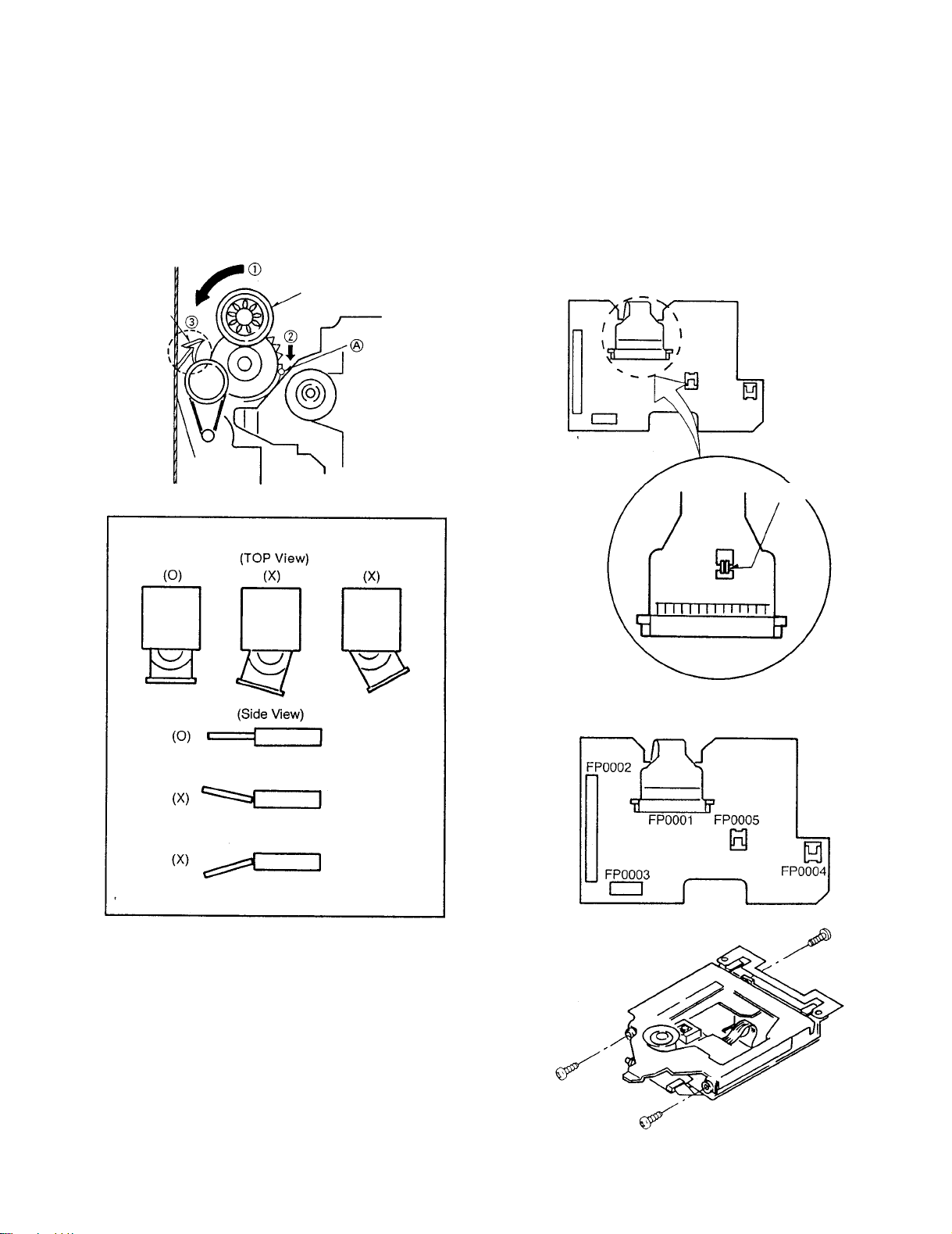
How to Replace
1. Preparation
1. Short the pickup short lands for protecting the
damage of the statics.
2. Remove all of the flexible cables on the connection
pcb.
3. Remove screws to divide the traverse unit
SHORT
4. Clamper
1. Mount the clamper plate before assembling the
loading base to the unit.
7
DV-K750/S700
DISASSEMBLY FOR REPAIR
2. Laser Pickup
1.Remove the screws fixing the pickup.
2.Remove the screws fixing the traverse motor.
Pickup
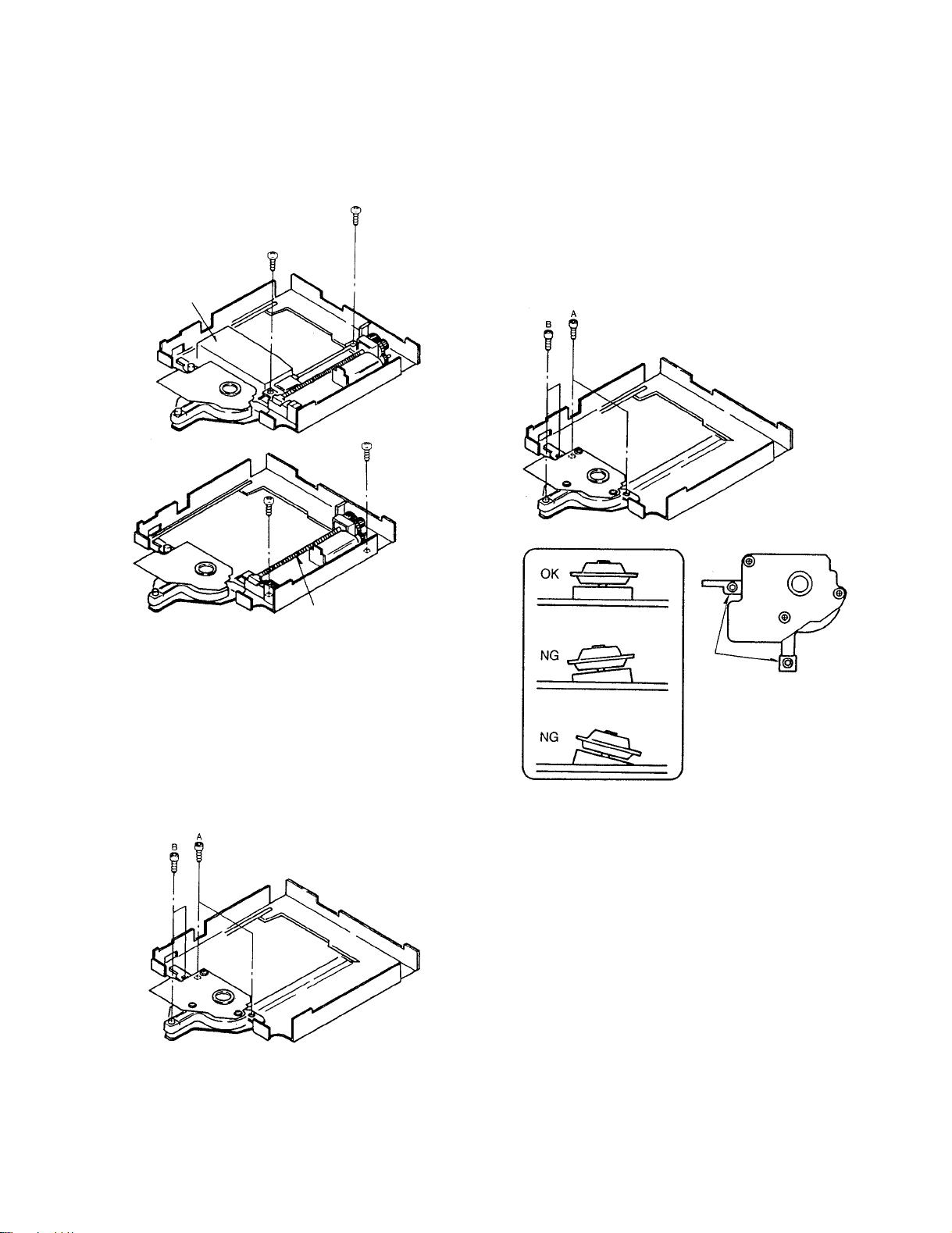
4. Assemble
1. Assemble the traverse unit and the pickup in the
reverse order of disassembly.
2. Fix the A screw and the B adjusting screw when the
disc motor unit mount.
3. Fix the B screw so that the disc motor unit is at a level
with the traverse unit.
TRAVERSE
UNIT
3. Disc Motor
1. Remove the A screw and the B screw in the order.
Note: No need to remove the laser pickup when disc
motor replace procedure.
B SCREW
(BLK)
8
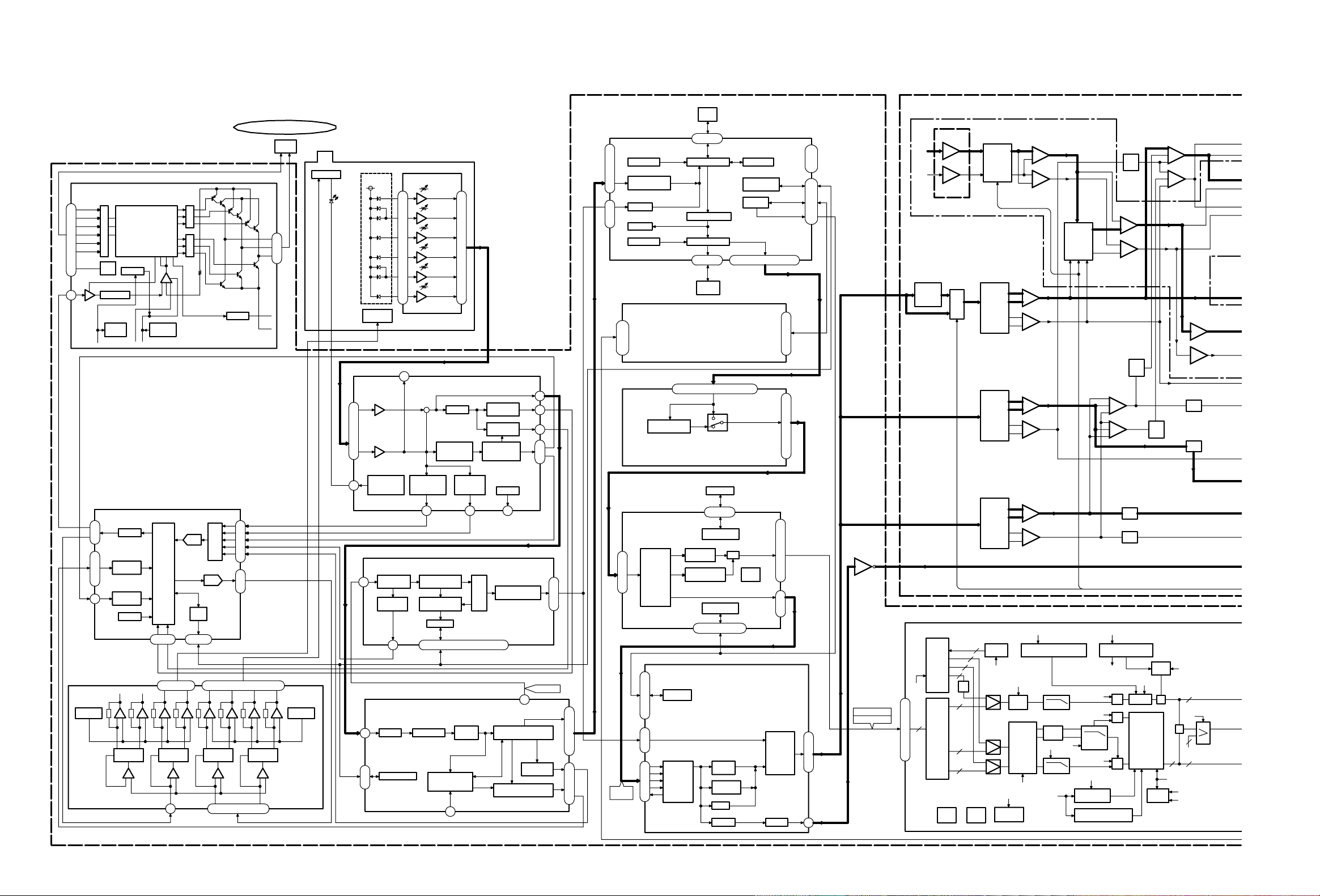
IC4001
A-DEC
IC2001
SERVO PROCESSOR
DV-K750 ONLY
MIC INPUT
(X25- )
DA/MIX/OUTPUT
DESCRAMBLE
IC6301
IC3511
V-DEC
IC3501
MAIN CPU
IC6031
IC6022
IC6021
IC6001
DEM/ECC
IC7501
CD-DSP
READ CHANNEL
IC7001
PRE AMP
IC5001
IC2051
IC001
HEAD AMP
SERVO
DRIVE
DM DRIVE
IC2071
DVD MECHA-MAIN P.C.B. (MAIN CBA)
NTSC/PAL ENCODER D/A
IC3532
C+
C-
+
-
LFE+
LFE-
-
+
SL+
SL-
SR-
SR+
+
-
-
+
-
-
+
-
+
-
L+
L-
R+
R-
+
-
+
-
-
-
-
-
-
-
-
-
+
+
+
+
2
-
+
-
+
-
++
-
-+-+-+-+-+-+-
+++
-
-
+
-
-
-
-
KARAOKE CONT.
DIGITAL
8
10
-
-
47
SELECTOR
55
54
49
-
32
42
46
-
PCM
LINEAR
MPEG 1
LAYER 2
DATA I/F
2
3
AUDIO-
4
6
37
HOST I/F
23
IC4002
STREAM
IEC958
57
FORMAT
AC-3
3
PWM
2
43
42
47
46
64
MPXA/D 81
74
79
75
82
DSP
D/A
CPU
I/F
90
91
62 63 12-28
MOTOR
CONTROL
SEEK
CONTROL
TIMER
DRIVE CONT.
IC1
IC23
SELECT
D.R.I.V.E.
IC9
(2/2)
HPF
HPF
IC9
(1/2)(1/2)
IC7
IC3
DAC
(2/2)
IC7
IC6
IC4
(1/2)
(2/2)
IC6
DAC
HPF
(2/2)
IC16
(1/2)
IC16
LPF
IC14
IC14
(2/2)
(1/2)
dB
-3.5
-3.5
dB
DAC
IC2
(2/2)
(1/2)
IC5
IC5
IC15
(2/2)
IC15
(1/2)
dB
-9.5
IC10
(1/2)
IC10
(2/2)
IC
KARAOKE
IC19
MIC2
MIC1
IC29
(1/2)
IC29
(2/2)
IC21
IC22
(2/2)
VOL
ELECTRIC
(1/2)
IC22
DVD MPEG 2
9
AUDIO PES PACKET
-
-
39
36
3
BUS MASTER 2
2,4-16,33-35,42-45,57-59
22
-
19
28
17
-
51
REF.CLK
8
99
9
8
8
8
BUS
BUS
DVID
RESET
SYNCHRO
BUS
BUSBUS
BUS
DECODER
I C BUS
BUS
BUS
B1
CKREF
CKREF
BUS
BUSB1
BUSBUS
BUS
BUS
6
6
6
3
RESET TEST
1
0
COLOR SUBCARRIER
SYNTHESIZER
COLOR
BURST GEN
CLOCK
GEN
C
+
AND GAIN
MODULATOR
UIO
W1
INT
OFFSET
6MHz
INT
INT
1.3MHz
1.6 OR
Q
0.5MHz
DELAY
DEMUX
CB
CR
MATRIX
U10
W1
DELAY
CB
CR
Y
INT
BARS
COLOR
CR
Y
CB
CLUT
SYNC
GEN
GENERATOR
COPY PROTECTIONCLOSED-CAPTION AND
CGMS GENERATORS
10
11
9
13
14
15
12
16
-
64
59
90
89
83
82
85
86
84
87
AV
SYNC
SUB PICTURE
DECODER
DECODER
S-DRAM
VIDEO
MIX
DECODER
106-159
S-DRAM I/F
17,22-26,31-39
HOST I/F
2
16
18
STREAM
SYSTEM
19
17
57
-
51
-
32
43
44
45
55
4MB
PSRAM
SRAM
IMB
202
-
200
CONTROLLER
DRIVE
CPU I/F
ARBITOR 2
EDC
DE-SCRAMBLER
CD-PRE
ECC CORE
8-16
DEMODULATOR
ARBITOR 1
47-77
BUS MASTER 1
83-113
--
152
127
124
17
20
18
36
34
38
40
39
37
122
159,168,175-191,193
CPU I/F
55
454443424140
SUBCODE
PROCESSING
26
28
29
36
CONTROL
MOTOR
37 4739
EFM
SEPARATOR
DATA
INTERPOLATION
DEMODULATOR
& MUTING ETC.
27
3
ECC
FE
TE
17
10
12
11
9
DISC MOTOR
SPEED DETECTOR
JITTER
DETECTOR
DATA SYNCHRONIZER
PLL
CONTROLLER
DETECTOR
OFFSET
RD FREQUENCY
AUTO
SLICER
EQUALIZERAGC
27
28
62
4
6
7
27
5
28
91127
33
30
43
64
48
VREFDETECTOR
HF
ENVELOPE
CONTROLLER
BALANCE
FOCUS-
DIFFERENTIAL
PHASE
DETECTORDELAYLINE
CONTROLLED
VOLTAGE-
DETECTOR
OFFTRACK
5
CONTROLLER
49
AMP
AMP
74
76
75
69
73
70
AGC
POWER
LASER
DETECTOR
DROP-OUT
MOTOR
TRAVERSE
LD
ACTUATOR
PD
I/V AMP
I/V AMP
I/V AMP
I/V AMP
I/V AMP
I/V AMP
24
23
21
18
20
17
4
8
6
10
12
2
20
1718
1098765
DETECTOR
DIRECTION
DETECTOR
DIRECTION
1/2PVCC1/2PVCC
DETECTOR
DIRECTIONDIRECTION
DETECTOR
26
25
1
STOP
START/
EA
ABSOLUTE
LOGIC
FG
12
DISC
MOTOR
HEAT
PROTECT
+
CD EFM
VCD MPEG 1
CORE
DE-SCRAMBLE
MATRIX HALL AMP
10
9
8
5
4
3
2
AMPAMP
LOGICAL
CIRCUIT
HALL
BIAS
IC12
(1/2)
IC12
(2/2)
DV-K750/S700 DV-K750/S700
BLOCK DIAGRAM
9
10
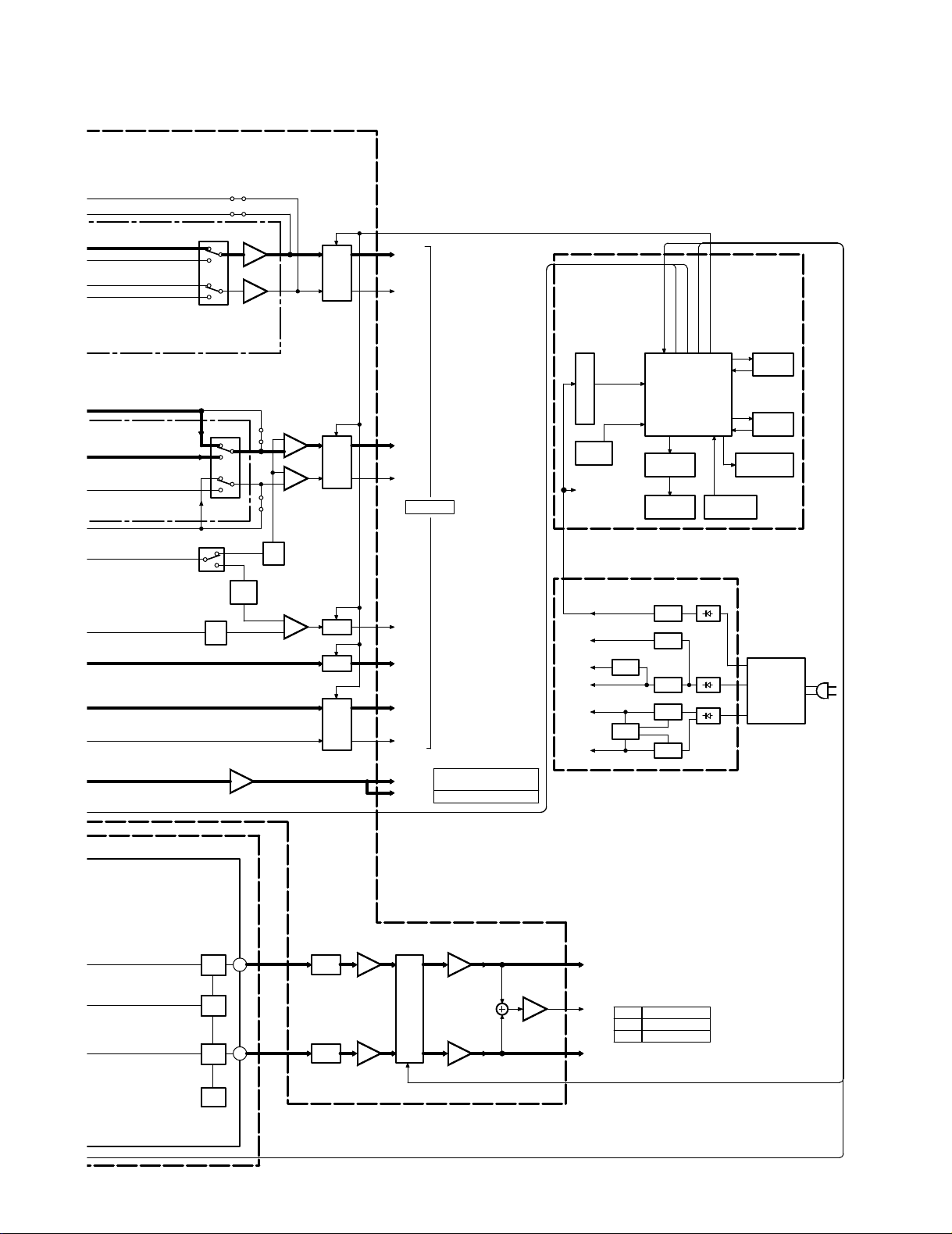
DV-S700/DV-K750
POWER SUPPLY
DISPLAY
-
-
W86W84
-
-
-
-
W155
W156
+
+
(MECHA)
12V
D503
D502
D501
5V
IC501
IC503
MAIN CONT.
IC602
Q27,28
OSD CONT.
Q503-12V
IC506
12V Q502
3.3V
5V IC502
TRANSFORMER
POWER
IC504
D5V
FL-AC
V-FL
MAIN CONT.
MUTE CONT. 1,2,3,4
OSD CONT.
DRIVE CONT.
KARAOKE CONT.
DOT DRIVER
u-COM 5V
IC605
S-RAM
KEY/SWITCH
REMOTE
STANDBY/DVD
DECODER
LED
D611,612
FL-DISPLAY
MUTE3
MUTE4
Q7,9
Q1-4
MUTE1
MUTE1
Q21-24
Y
COMP.
C
75 DRIVER
IC303
C
(2/2)
IC302
75 DRIVER
Y
(1/2)
IC302
75 DRIVER
309
C
Q306-
6dB
FILTER
Y
6dB
Q301305
IC301
O.S.D.
FILTER
SR
SL
CENTER
-5.0
dB
SW
(2/2)
IC17
dB
-15.0
IC18
Lch
Rch
dB
-4.5
(2/2)
(1/2)
IC8
IC8
IC31
IC20
MIX Lch
MIX Rch
IC11
IC11
ED1
IC603
VFD
C623
POWER BACK-UP
IC609
CD-TEXT
CONTROL u-COM
A601
SENSOR
IEC OUT
COAX: 0.5Vp-p/75
(Wave length 660nm)
OPT: -15dBm~-21dBm
1.2V/300
1Vp-p/75
1Vp-p/75
0.286Vp-p/75
Y
COMP.
C
COAXIAL
OPTICAL
MUTE2
Q15-18
Q8,10
36
38
9BIT
D/A
9BIT
D/A
D/A
REF.
9BIT
D/A
(2/2)
(1/2)
Ω
Ω
Ω
Ω
Ω
Ω
Ω
Ω
DV-K750/S700
BLOCK DIAGRAM
11
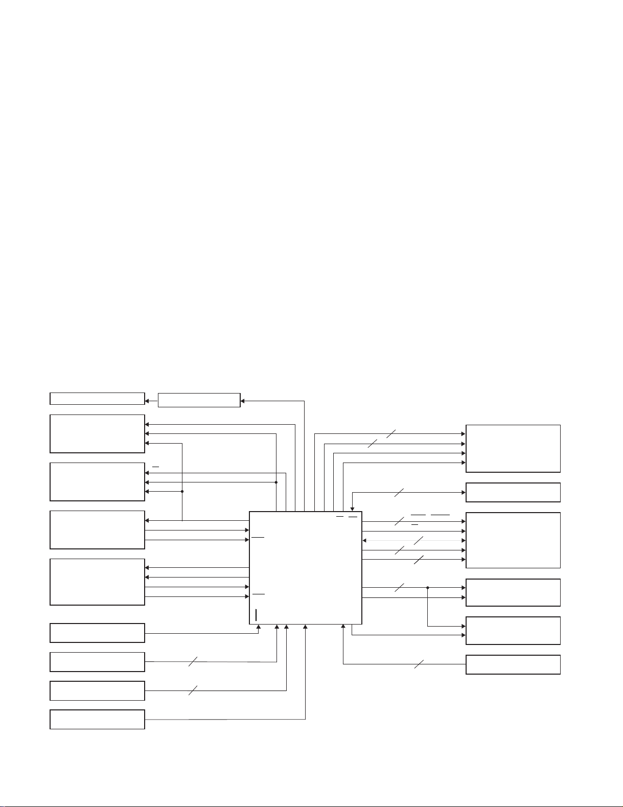
DV-K750/S700
(X25) ED1
(X25) IC
CE
DI
CL
CS
SIN
SCLK
SCLK1
RxD1
IRQ2
SCK0
TxD0
TxD1
RxD0
IRQ1
IRQ0
AN 0, 1
AN2
D0~D7
A0~A15
DV-S700 /
DV-K750
RD, WR
4 ANALOG MUTE
SUBW, AC-3, KARAOKE
DVD LED
POWER
AS
BUSY, DATA
READ / WRITE
DATA
Address
BANK
IFL
STB
IFS, IFD
CK, DATA
3
2
2
8
16
3
2
2
SCLK
SRDT
DQST
DSPSCLK
CMD
STATUS
READY
2
2
(X25) IC301
(X25) IC604
(X25)
IC602
(X25) J1
(X25) IC605
(X25) IC19
(X25) IC21
(X25) S613
(W02) IC6031
(X05) A601
(X25) IC603
FL DISPLAY
VFD Display
ON SCREEN DISPLAY
CD TEXT DECODER
MECHA MAIN u-COM
VFD DOT DRIVER
LC75710N
MB90089FP-188
LC89170M
MN1020819N2C
HD6433397A48F
MAIN u-COM
OTHER CIRCUIT
SYSYTEM CONTROL
HM62256BLFP-8T
TC9409BF
TC9210P
SRAM
KARAOKE
ELECTRIC VOL.
SHUTTLE SW(JOG DIAL)
REMOTE SENSOR
KEY BOARD
REGION CODE/MODEL
OUTPUT
CIRCUIT DESCRIPTION
1. DV-K750 is constructed by DV-S700 and Karaoke function.
When the port #34 of the microprocessor will be
connected to High level, specifications is the DV-S700. To
be connected to Low level will be the DV-K750.
2. DVD disc will have the region code in it.
(Refer to page 15.)
3. Initialization of unit
a) POWER : STANDBY
b) 2-CHANNEL : OFF
c) KARAOKE : OFF
d) MIC-1 VOLUME : 6
e) MIC-2 VOLUME : 6
f) MIC ECHO : 8
g) KEY CONTROL : ±0
4. Main microprocessor : HE643339A48F.
4-1 Block diagram
h) MEMORY✽ : NON FIX
I) PROGRAM PLAY✽ : NON FIX
j) REPEAT✽ : NORMAL PLAY
k) VISUAL and AUDIO LIMIT : LEVEL 8 (NON LIMIT)
l) PASS WORD of
VISUAL and AUDIO
LIMIT (DVD) : NON LIMIT
m) AUDIO OUTPUT (DVD) : ORIGINAL
n) CAPTION (DVD) : AUTOMATIC
o) DISC MENU (DVD ) : ENGLISH
p) TV SCREEN (DVD) : LETTER BOX
q) OSD display : ON
r) CENTER CHANNEL : ON
s) SUB-WOOFER CHANNEL : ON
t) SURROUND CHANNEL : ON
✽ non backup
12
DV-K750/S700
CIRCUIT DESCRIPTION
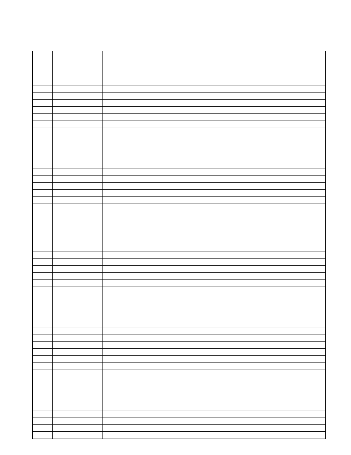
4-2 Pin description.
No Pin Name I/O Description
1 /RESET I Input port of microprocessor reset
2,3 X/ETAL I / O Port of ceramic oscillator
4,5 MD0 / 1 I Operation mode 0 and 1
6 /NMI – No use
7 /STBY – No use
8 VCC – Power supply (+5V)
9 M-SCLK O Output port of clock signal to the main processor (DSPSCLK)
10 M-STAT O Input port to the main microprocessor (SRDT)
11 M-CMD O Output port to the main processor (DQSY)
12 VSS – GND
13 POW.LED O Standby LED (H : standby)
14 – – No use
15 /RAM-CS O Access mode of extra-address ( / CS)
16 /RAM-WR O Read mode of extra-address ( / WE)
17 /RAM-RD O Write mode of extra-address ( / OE)
18 /REMOTE I Input port of remote signal
19 /M-READY I Ready/resend signal to the main microprocessor
20 /T-DQSY I Input port of read signal from CD-TEXT IC (DQSY)
21 SBUSY I/O Synchro busy signal (BUSY)
22 SDATA I/O Synchro data signal (DATA)
23 DVD LED O DVD LED (H : light, L : dis-light)
24 POWER O Power LED (H : ON, L : OFF)
25 MUTE 4 O Mute 4, analog mute (SW)
26 MUTE 3 O Mute 3, analog mute (C)
27 MUTE 2 O Mute 2, analog mute (SL / SR)
28 MUTE 1 O Mute 1, analog mute
29 AVCC – A/D standard voltage
30,31 KEY I Key input 1, 2
32,33 – – No use
34 SET I Model selection (H : DV-S700, L : DV-K750)
35, 36 SMUTE1, 2 I Input port of shuttle switch 1, 2
37 SMUTE3 I Output selection of 6 channel (H : yes, L : no)
38 AVSS – GND
39 KARA O KARAOKE output (H : on, L : off)
40 SUBW O Sub woofer output (H : on, L : off)
41 AC3 O AC-3 output (H : on, L : other)
42 IFL2 O Latch signal of serial control to electronics volume IC (TC9210P) (STB)
43 IFL1 O Latch signal of serial control to KARAOKE IC (TC9409BF) (IFL)
44 IFD O Serial data output to electronics volume IC and KARAOKE IC (DATA, IFD)
45 IFS O Serial clock output to electronics volume IC and KARAOKE IC (CK, IFS)
46 BANKA O S-RAM bank selection A
47 VCC – Power supply (+5V)
48 CE I Chip enable port
49-52 A14-11 I No use
53-55 A10-8 O S-RAM access bus address
56 VSS – GND
57-64 A7-0 O S-RAM access bus address
65-72 D0-7 I/O S-RAM access bus data
73 VSS – –
74,75 BANK B,C O S-RAM bank select b, c
76 VFD-CE O VFD display IC serial control latch (CE)
77 OSD-CS O OSD display IC serial control latch (STB)
78 OSD/VFD-SD O OSD display IC/VFD display ic serial data output (SIN / DI)
79 T-SRDT I CD-TEXT IC data input (SRDT)
80 VFD-CL O CD-TEXT/OSD/VFD IC serial clock (SCLK / SCLK / CL)
13
 Loading...