

Page 1
COMPACT
COMPACT
DV-4900 DV-4070
DVF-R9030
DVF-R7030
This instruction manual is used to
describe multiple models listed above.
Model availability and features
(functions) may differ depending on the
country and sales area.
DIGITAL VIDEODIGITAL VIDEO
DIGITAL AUDIO
TEXTTEXT
Multiple DVD VCD CD
Player
B60-4707-00 00 CS (T,K,M,X) AP @0004
Page 2
Before applying power
Caution : Read this page carefully to ensure safe operation.
Units are designed for operation as follows.
U.S.A. and Canada.................................AC 120 V
Australia ......................................... AC 110-240 V
Europe and U.K.................................... AC 230 V
Other countries .............................. AC 110-240 V
For the United Kingdom
Factory fitted moulded mains plug
1. The mains plug contains a fuse. For replacement, use only a 13-Amp ASTA-approved (BS1362) fuse.
2. The fuse cover must be refitted when replacing the fuse in the moulded plug.
3. Do not cut off the mains plug from this equipment. If the plug fitted is not suitable for the power points
in your home or the cable is too short to reach a power point, then obtain an appropriate safety approved
extension lead or adapter, or consult your dealer.
If nonetheless the mains plug is cut off, remove the fuse and dispose of the plug immediately, to avoid a
possible shock hazard by inadvertent connection to the mains supply.
IMPORTANT : The wires in the mains lead are coloured in accordance with the following code:
Blue : Neutral Brown : Live
Do not connect those leads to the earth terminal of a three-pin plug.
Safety precautions
WARNING : TO PREVENT FIRE OR ELECTRIC SHOCK, DO NOT EXPOSE
THIS APPLIANCE TO RAIN OR MOISTURE.
CAUTION
RISK OF ELECTRIC SHOCK
DO NOT OPEN
THE LIGHTNING FLASH WITH ARROWHEAD SYMBOL, WITHIN AN
EQUILATERAL TRIANGLE, IS INTENDED TO ALERT THE USER TO THE
PRESENCE OF UNINSULATED “DANGEROUS VOLTAGE” WITHIN THE
PRODUCT’S ENCLOSURE THAT MAY BE OF SUFFICIENT MAGNITUDE
TO CONSTITUTE A RISK OF ELECTRIC SHOCK TO PERSONS.
CAUTION: TO REDUCE THE RISK OF ELECTRIC SHOCK,
DO NOT REMOVE COVER (OR BACK). NO USERSERVICEABLE PARTS INSIDE. REFER SERVICING TO
QUALIFIED SERVICE PERSONNEL.
The marking of products using lasers
(Except for some areas)
CLASS 1
LASER PRODUCT
The marking is located on the rear panel and says
this product has been classified as Class 1. It means
that there is no danger of hazardous radiation
outside the product.
CAUTION
INVISIBLE LASER RADIATION
WHEN OPEN AVOID EXPOSURE
TO BEAM
THE EXCLAMATION POINT WITHIN AN EQUILATERAL TRIANGLE IS
INTENDED TO ALERT THE USER TO THE PRESENCE OF IMPORTANT
OPERATING AND MAINTENANCE (SERVICING) INSTRUCTIONS IN THE
LITERATURE ACCOMPANYING THE APPLIANCE.
Inside this laser product, a laser diode classified as
Class 2 laser radiation is contained as alerted by the
internal caution label shown above. To avoid
exposure to laser beams, do not open the cover.
2
Page 3
Features
Compatible with DVD AUDIO, one of the latest
digital audio formats
The DVD AUDIO reproduces 2-channel, 192
kHz, 24-bit sampled digital audio or 6-channel,
96 kHz, 24-bit sampled audio. This innovative
technology has made possible audio
reproduction in unprecedented high quality.
Picture information and character information
(ALBUM TEXT) are also provided.
Versatile DVD VIDEO Functions
The DVD VIDEO provides horizontal resolution
of 430 lines, which exceeds that of DVD or S
VHS video (400 lines) or laserdisc (430 lines).
The difference is obvious when the screen size is
increased.
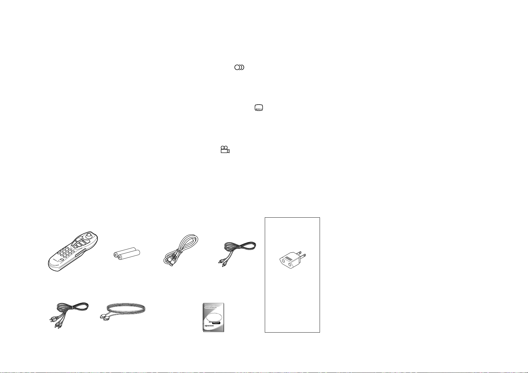
Accessories
Joystick remote control
unit (1)
Batteries (R6/AA)
(2)
S Video cable
(1)
Multi-audio function: With DVD discs marked
8
with the
icon, the desired language can be
played back by selecting it from up to 8
languages. (The number of available languages
is variable depending on the discs.)
Multi-subtitle function: With DVD discs
32
marked with the
icon, the subtitle language
can be selected from up to 32 languages. (The
number of subtitle languages is variable
depending on the discs.)
Angle function: With DVD discs marked with
the
icon, a single object can be viewed in
9
up to 9 angles by switching. (The number of
available angles is variable depending on the
discs.)
Video cable
(1)
AC plug adapter (1)
Unpacking
Unpack the unit carefully and make sure that all accessories
are put aside so they will not be lost.
Compatibility with Wide Range of Digital
Surround Software
The unit incorporates Dolby Digital decoder,
DTS decoder, MPEG multi-channel decoder and
Packed PCM decoder so that the users can enjoy
the sound of real cinemas. The unit can also be
connected to the user's existing TV set
6-Channel Output Terminals
These output terminals can be connected to an
amplifier with 6-channel input compatibility to
enjoy high-bit, high-sampling rate multi-channel
sound.
5-Disc Carousel Disc Changer
The disc tray can accommodate up to 5 discs and
the disc can be changed while another disc is
being played.
Audio cables
(3)
Optical fiber cable
(1)
Instructoin manual/
separate User's Guide (1)
Multiple DVD VCD CD
Use to adapt the plug
on the power cord to
the shape of the wall
outlet. (Accessory only
for regions where use is
necessary.)
Examine the unit for any possibility of shipping damage. If
your unit is damaged or fails to operate, notify your dealer
immediately. If your unit was shipped to you directly, notify
the shipping company without delay. Only the consignee (the
person or company receiving the unit) can file a claim against
the carrier for shipping damage.
We recommend that you retain the original carton and
packing materials for use should you transport or ship the
unit in the future.
Keep this manual handy for future reference.
3
Page 4

Contents Caution : Read the pages marked carefully to ensure safe operation.
Before applying power ................... 2
Safety precautions................................... 2
Features .......................................................... 3
Accessories ..................................................... 3
Systems and Types of Playable Discs ............. 5
Unplayable Discs ............................................ 5
Icons Inscribed on DVD Discs ....................... 6
Region Codes of This Player (DVD VIDEO disc
only) ............................................................... 6
Region codes of the DVD VIDEO discs that can be
played with this player..............................................7
Region codes in the world ....................................... 7
Video Formats ................................................ 8
Checking the Video Format ..................................... 8
Chapter 1: Connection of Equipment... 9
Connection with a TV or Stereo System....... 10
To Connect a TV ...................................................... 11
To Connect a Stereo System ................................... 11
To Set Up of the Player ........................................... 11
Connection with an AV Amplifier ................. 12
To Connect an AV Amplifier.................................. 13
To Setup of the Player ............................................ 13
Chapter 2: Various Setups .................. 14
Preparation of Remote Control Unit ........... 14
Installing the batteries : ......................................... 14
Remote control range :........................................... 14
Turning Power on ........................................ 14
Standby mode:........................................................ 14
Control Buttons Used in Setups .................. 15
Basic Operations in Setup Screen ................ 15
When "MAIN" is selected in "SET UP MENU": ... 16
When "SOUND" is selected in "SET UP MENU": 16
When "VISUAL" is selected in "SET UP MENU": 17
"MAIN" Setting ............................................. 18
"Rating" Setting ...................................................... 18
"TV Aspect" Setting ................................................ 20
"TV Mode" Setting ................................................. 20
"TV Monitor Type" Setting .................................... 21
"DVD VIDEO Mode" Setting................................. 22
"OSD Position" Setting.......................................... 22
"On Screen Message" Setting ................................ 23
"IPB Display" Setting ............................................. 24
"SOUND" Setting.......................................... 26
"Digital Audio PCM Down Conversion"
Setting.................................................................. 26
"Digital Audio Dolby Digital" Setting .................. 26
"Digital Audio DTS" Setting .................................. 27
"Digital Audio MPEG" Setting .............................. 28
"Speaker Setting" .................................................... 28
"Audio During Search" Setting ............................. 32
"Dynamic Range Control" Setting ........................ 32
"Audio Filter" Setting ............................................ 33
"VISUAL" Setting .......................................... 34
"Player Menu Language" Setting ........................... 34
"Disc Menu Language" Setting .............................. 34
"Audio Language" Setting...................................... 35
"Subtitle Language" Setting ................................... 36
"Still Mode" Setting ............................................... 36
"FL Mode" Setting .................................................. 37
"NTSC = PAL" Setting (Except for the U.S.A. and
Canada) ................................................................... 38
"SCART Output Select" Setting (For Europe and U.K.)
............................................................................. 38
Disc Language Code Table..................................... 40
Chapter 3: Other Information ............ 41
To Be Noted .................................................. 41
Glossary........................................................ 43
Index ............................................................ 45
Specifications ............................................... 46
As an
ENERGY STAR
Kenwood Corporation has determined
that this products meets the ENERGY
guidelines for energy efficiency.
STAR
®
This product can save energy. Saving energy reduces
air pollution and lowers utility bills.
®
Partner,
4
Page 5
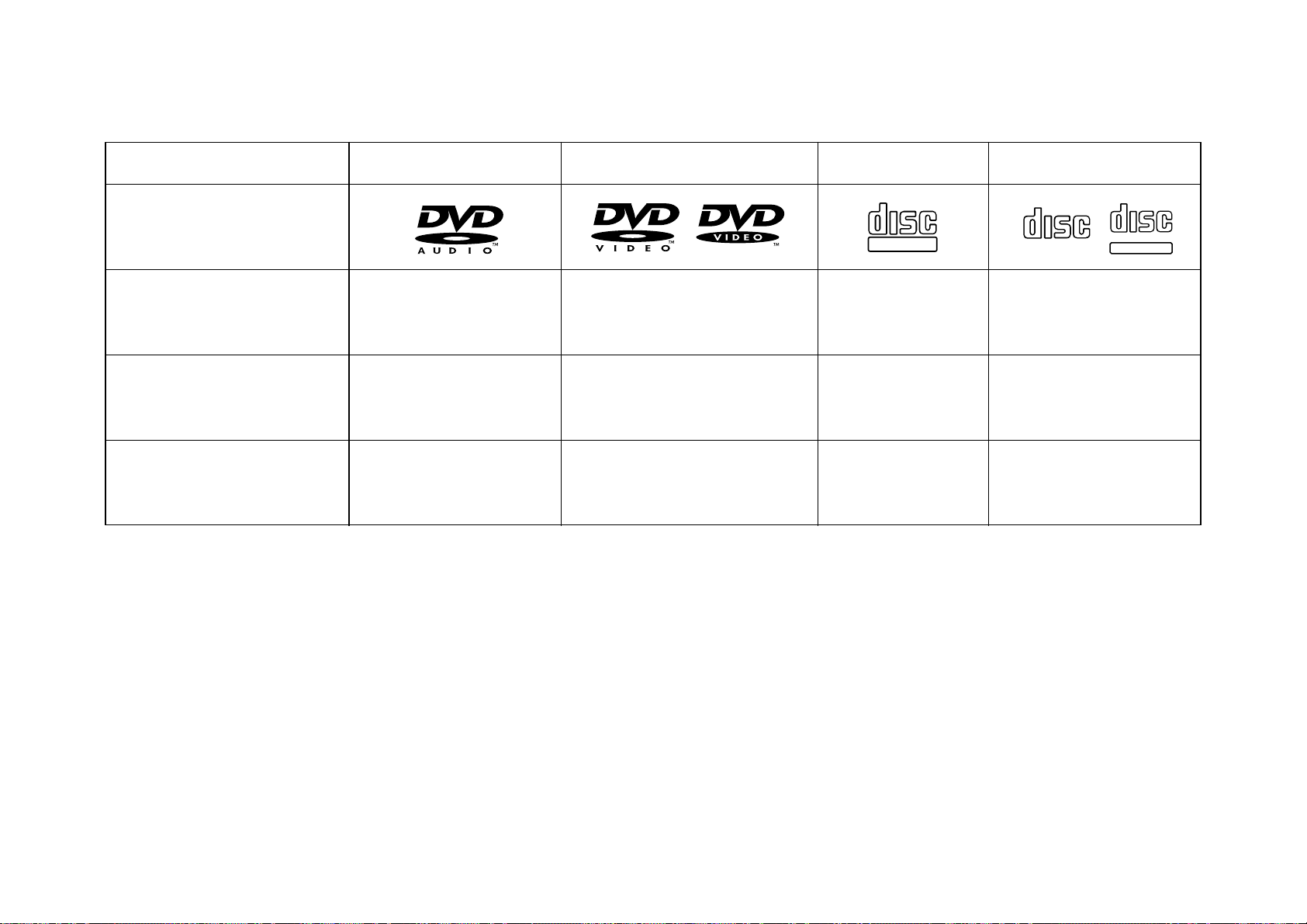
Systems and Types of Playable Discs
Playable Disc
Logo mark
Disc size
Played side(s)
Sampling rate
Unplayable Discs
DVD AUDIO DVD VIDEO CD
12 cm or 8 cm
1 or 2
Max. 192 kHz/24 bit (2CH) Max. 96 kHz/24 bit (2CH) 44.1 kHz/ 16 bit (2CH) 44.1 kHz/ 16 bit (2CH)
12 cm or 8 cm
1 or 2 1 side only 1 side only
VCD
COMPACT
DIGITAL VIDEO
12 cm or 8 cm
COMPACT
DIGITAL AUDIO
12 cm or 8 cm
COMPACT
DIGITAL AUDIO
TEXT
Never attempt to play a Photo CD, CD-R or CDRW disc on this unit. Otherwise, the disc data may
be destroyed.
Other discs which cannot be played on this unit:
¶ SACD, DVD-ROM, DVD-R/RAM, DVD-RW, CD-
ROM, VSD, CDV*, CD-G*, CD-EG*, CDEXTRA*, etc.
* Only the audio part can be reproduced.
¶ A DVD VIDEO disc with a region code which
does not match this unit or without a region
code. For details, see "Region Codes of This
Player". 6
¶ When the video format of a disc differs from that
of the TV in use, the disc cannot be played
normally. For details, see "Video Formats".
8
5
Page 6
Icons Inscribed on DVD Discs
ALL
Indicates the playable region code.
8
Indicates the number of languages in the
audio. The figure in the icon shows the number (max.
8 languages).
32
Indicates the number of available subtitle
languages. The figure in the icon shows the number
(max. 32 subtitle languages).
9
Indicates the number of viewing angles which
can be viewed with the angle function. The figure in
the icon shows the number (max. 9 angles).
16:9 LB
ratios. LB stands for Letter Box and PS stands for Pan
& Scan. (The example shown means that the 16:9 video
can be converted into letterbox.)
Indicates the number of available aspect
Region Codes of This Player
(DVD VIDEO disc only)
A region code defined for each country or area is
assigned for each DVD VIDEO player, so it cannot
play a DVD VIDEO disc if its region code do not
match that of this unit. Also, a disc which does not
contain any region code may sometimes be unable
to be played on the player.
When purchasing a DVD VIDEO disc, make sure that
it has a region code which can be played on your
player.
Region Code of Player:
Usable Country or Area : Canada, United States,
American Samoa, Bermuda, Johnston Island,
Midway Islands, Puerto Rico, St. Pierre and
Miquelon, United States Virgin, Wake Island
Region Code of Player :
Usable Country or Area : Albania, Andorra,
Austria, Bahrain, Belgium, Bosnia and
Herzegovina, Bulgaria, Croatia, Cyprus, Czech,
Denmark, Egypt, Finland, France, Germany,
Greece, Hungary, Iceland, Iran, Iraq, Ireland,
Israel, Italy, Japan, Jordan, Kuwait, Lebanon,
Lesotho, Liechtenstein, Luxembourg,
Macedonia, Malta, Monaco, Netherlands,
Norway, Oman, Poland, Portugal, Qatar,
Romania, San Marino, Saudi Arabia, Slovakia,
Slovenia, South Africa, Spain, Swaziland,
Sweden, Switzerland, Syrian Arab Republic,
Turkey, United Arab Emirates, United Kingdom,
Vatican City State, Yemen, Yugoslavia, Channel
1
2
Islands, Faeroe Islands, Gibraltar, Greenland, Isle
of Man, Svalbard and Jan Mayen Islands
Region Code of Player :
Usable Country or Area : Brunei Darussalam,
Cambodia, Indonesia, Korea, Laos, Malaysia,
Myanmar, Philippines, Singapore, Thailand,
Viet Nam, East Timor, Hong Kong, Macau,
Taiwan
Region Code of Player :
Usable Country or Area : Antigua and
Barbuda, Argentina, Australia, Bahamas,
Barbados, Belize, Bolivia, Brazil, Chile,
Colombia, Costa Rica, Cuba, Dominica,
Dominican Republic, Ecuador, El Salvador,
Fiji, Grenada, Guatemala, Guyana, Haiti,
Honduras, Jamaica, Kiribati, Marshall
Islands, Mexico, Micronesia, Nauru, New
Zealand, Nicaragua, Palau, Panama, Papua
New Guinea, Paraguay, Peru, Saint
Christopher and Nevis, Saint Lucia, Saint
Vincent and the Grenadines, Samoa,
Solomon Islands, Suriname, Tonga, Trinidad
and Tobago, Tuvalu, Uruguay, Vanuatu,
Venezuela, Anguilla, British Virgin Islands,
Cayman Islands, Christmas Island, Cocos
Islands, Cook Islands, Falkland Islands,
French Guiana, French Polynesia,
Guadeloupe, Guam, Martinique, Montserrat,
Netherlands Antilles, New Caledonia, Niue,
Norfolk Island, Northern Mariana Islands,
Pitcairn, Tokelau, Turks and Caicos Islands,
Wallis and Futuna Islands
3
4
6
Page 7
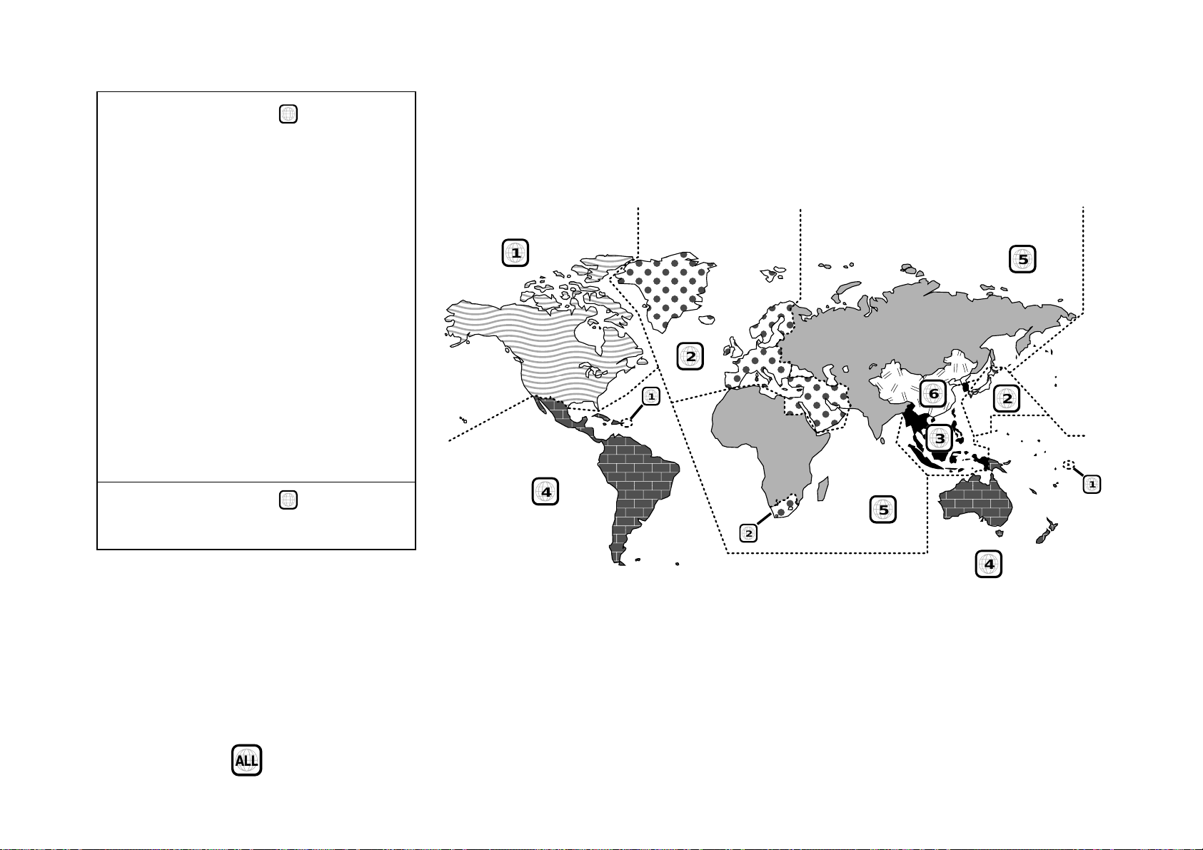
Region Code of Player :
Usable Country or Area : Afghanistan, Algeria,
Angola, Armenia, Azerbaijan, Bangladesh,
Belarus, Benin, Bhutan, Botswana, Burkina Faso,
Burundi, Cameroon, CapeVerde, Central Africa,
Chad, Comoros, Congo, Cote d'Ivoire, Djibouti,
Equatorial Guinea, Eritrea, Estonia, Ethiopia,
Gabon, Gambia, Georgia, Ghana, Guinea,
Guinea-Bissau, India, Kazakhstan, Kenya, Kyrgyz
Republic, Latvia, Liberia, Libya, Lithuania,
Madagascar, Malawi, Maldives, Mali,
Mauritania, Mauritius, Moldova, Mongolia,
Morocco, Mozambique, Namibia, Nepal, Niger,
Nigeria, North Korea, Pakistan, Russia, Rwanda,
Sao Tome and Principe, Senegal, Seychelles,
Sierra Leone, Somalia, Sri Lanka, Sudan,
Tadzhikistan, Tanzania, Togo, Tunisia,
Turkmenistan, Uganda, Ukraine, Uzbekistan,
Zaire, Zambia, Zimbabwe, British Indian
Territory, Jammu and Kashmir, Mayotte,
Reunion, St. Helena ex. dep., Western Sahara
Region Code of Player :
Usable Country or Area : China
5
6
Region codes in the world
The DVD players are given a region code according to the country or area it is marketed, as shown in the following
map.
1
2
1
6
3
4
5
2
5
2
1
Region codes of the DVD VIDEO discs that can be played with this player
This player can play back a DVD VIDEO disc which
carries the corresponding code to the region code of
the player shown in the table above, a marking
containing the region code of the player or the “ALL”
marking shown below. Even when a DVD VIDEO disc
does not carry any indication of the region code, it
may sometimes unable to be played on this player due
to certain restrictions.
ALL
4
7
Page 8
Video Formats
The TV picture display and disc signal systems can be
divided roughly into two TV formats (NTSC and PAL).
They are variable depending on countries and areas.
This unit reproduces NTSC discs in NTSC format and
PAL discs in PAL format. If the video formats of the
disc and TV do not match, the disc cannot be
reproduced correctly. It is therefore required to select
the disc according to the TV set in use (country and
area).
TV formats in major countries
NTSC : Japan, Taiwan, Korea, USA, Canada, Mexico,
Philippines, Chile, etc.
PAL : China, U.K., Germany, Australia, New
Zealand, Kuwait, Singapore, etc.
Checking the Video Format
Check the video format of the VCD and DVD discs to
be played on the player as described below.
1. Check if the video formats of the TV to be used
and disc to be played match each other.
¶ For details, refer to the instructions provided with
the TV and disc.
2. When the TV is switchable between NTSC and
PAL, set the TV format according to the disc
format.
TV Format Playable Disc Format
NTSC only *
PAL only
NTSC/PAL
switchable
¶ Correct video cannot be reproduced if the video
formats of the TV and disc do not match.
NTSC*
PAL
NTSC/PAL
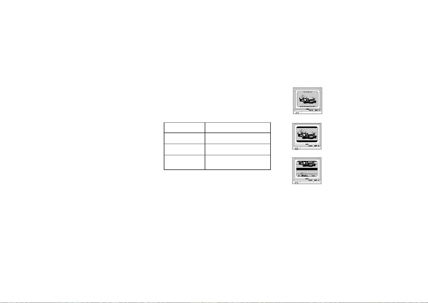
When the video formats are different : Try playing
the disc. If the video formats of the disc and TV do not
match, the played video may be black and white or become as shown below.
Top and bottom edges are not
displayed.
Top and bottom areas are
dark.
Picture turbulence due to sync
unmatching.
8
Page 9

Chapter 1: Connection of Equipment
Chapter 1: Connection of Equipment
Connections
This manual describes the standard, most typical
connections of the player. When an associated system
component is connected, also refer to their instruction
manuals.
For details on the connection of the following
components, see the indicated reference pages.
Connection with a TV or Stereo System 0
Connection with an AV Amplifier @
Before Start
Do not install the player in a place where the remote
control sensor is subjected to direct sunlight or the
light of a fluorescent lamp base on high-frequency
lighting (inverter system, etc.). Otherwise, the control
range of the joystick remote will be reduced.
Do not insert the power cord plugs of the player and
the connected components until all of the components
have been connected.
Be sure to insert all connection cables securely. If a
cable is plugged incompletely, lack of video, lack of
audio or noise may result.
Before connecting or disconnecting a connection cord,
be sure to unplug the power plug from the wall power
outlet. If a connection cable is connected or
disconnected while the power plug is left connected,
malfunction or equipment damage may result.
When a DVD AUDIO disc is played, the player can output
audio signals at very high frequencies. As this may
sometimes lead to speaker damage due to a high-volume
sound, do not set "Audio Filter" to "Filter 110 kHz"
when the speakers in use are not suitable for highfrequency reproduction. ‹
Malfunction of Microcomputer
In case the microcomputer malfunctions, making
operations impossible or showing wrong messages on
the display even if you connected everything properly.
When the microcomputer malfunctions, perform the
following procedure to reset the microcomputer and
return it to the normal condition.
1. While holding
press
POWER
- ON – OFF
.
7
on the player main unit,
2. The display on the main unit shows blinking
"INIT"(initializing), then shows "INIT OK!" (Ini-
tialization OK) to indicate that the microcomputer
is reset.
POWER
3. Press
press it again to turn it on.
¶ The resetting clears the setups stored in the
microcomputer and returns it to the factory-set
initial condition. After resetting, you should
perform the various setups of the player again
from the beginning.
on the main unit to turn it off, then
- ON – OFF
Also, be sure to check the actual sound level when
increasing or decreasing the volume control setting.
9
Page 10
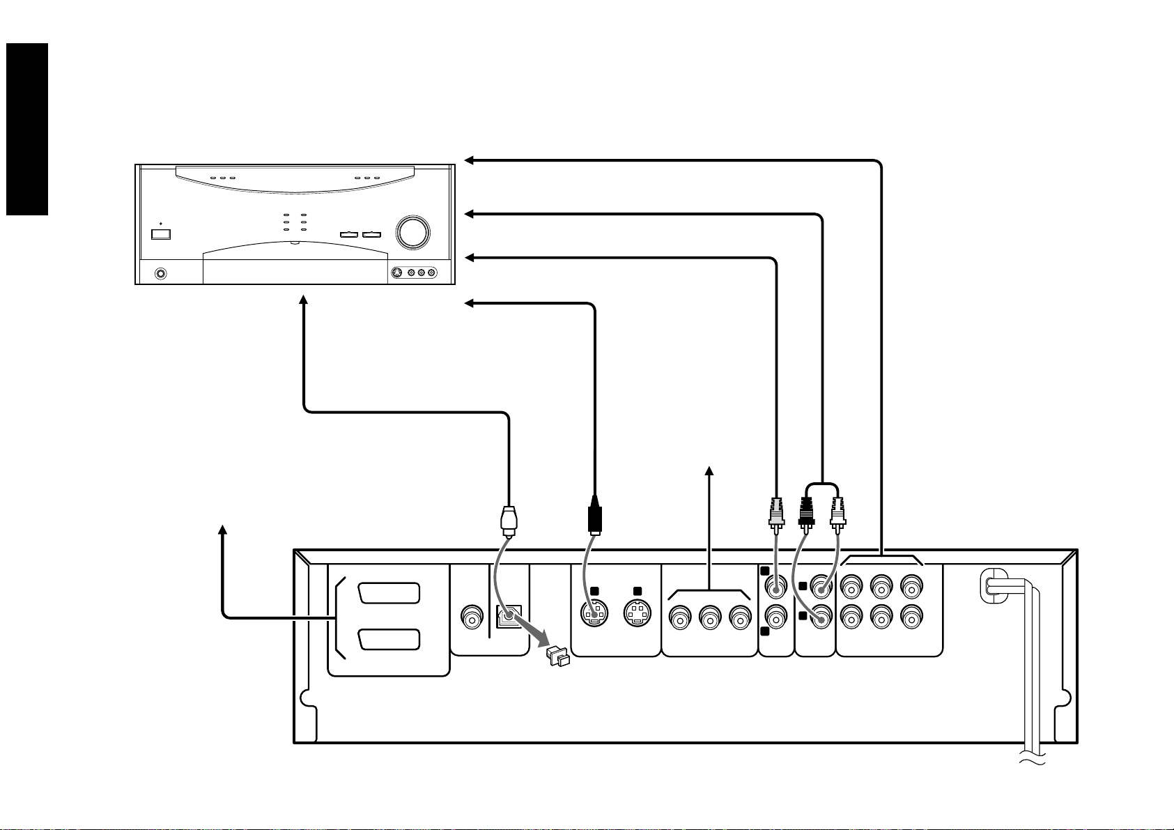
Connection with a TV or Stereo System
Chapter 1: Connection of Equipment
Connections
Audio connection: To audio input jacks
TV
Video connection: To video input jack
Component video connection:
To color difference (Cr) input jack
To color difference (Cb) input jack
To luminance (Y) input jack
S Video connection: To S Video input connector
SCART connection (For U.K. and Europe):
Connect the TV SCART connector to the TV's input connector.
Connect the VCR SCART connector to the VCR's input connector.
TV SCART
TV SCART
VCR SCART
VCR SCART
S Video cable (provided)
COAXIAL
OPTICAL
DIGITAL OUTPUT
(
PCM/BIT STREAM
)
Video cable (provided)
Video cable (optional)
Video cable (optional)
Video cable (optional)
1 2
12
S VIDEO OUTPUT
COMPONENT VIDEO OUTPUT
Audio cable (provided)
YCbCr
1
2
VIDEO
OUTPUT
L
R
MIX LINE
OUTPUT
Stereo system
Audio connection: To audio input jacks
Audio cable (provided)
FRONT SURROUND
6CH. OUTPUT
CENTER
SUB WOOFER
10
Select the video connection method according to the TV in use. When S-Video cable is connected, the ordinary video connection is not necessary.
Page 11

Connection with a TV or Stereo System
Chapter 1: Connection of Equipment
Connections
Do not insert the power cord plugs of the player and
the connected components until all of the components
have been connected.
For details on the connection terminals and functions
of the TV, refer to its instruction manual.
The video output from the player should be connected
directly to the TV. If the video output is connected
through a VCR, the picture displayed on the TV may
be disturbed due to the copy protect function.
To Connect a TV
Video connection: Connect the VIDEO OUTPUT jack
of the player to the video input of the TV using the
provided video cable.
S Video connection: If the TV has an S Video input
connector, connect the S VIDEO OUTPUT con-
nector of the player to it using the provided S Video
cable.
¶ As S Video separates video signal into the
luminance signal (Y) and color signal (C), it can
provide sharper pictures than ordinary video
connection.
Component video connection: If the TV has com-
ponent video input jacks, connect the Y, Cb and
Cr COMPONENT VIDEO OUTPUT jacks of the
player to the corresponding jacks on the TV using
video cables.
¶ As component video separate video signal into
the luminance signal (Y) and color difference
signals (Cb, Cr), it can provide sharper image
than the S Video connection.
¶ When the TV in use is a HDTV or "Hi-Vision"
TV, connect the component video signals from
the player only to the DVD-compatible input
jacks.
SCART connection (For Europe and U.K.): If the
TV or VCR has SCART connectors, connect the
TV SCART or VCR SCART connector of this unit
to the TV or VCR using SCART cables.
¶ The audio and video signals can be output using
a single cable. The signal output from the TV
SCART connector can be switched between
composite video, S Video and RGB. (The VCR
SCART connector always outputs composite
video signals so its output signals cannot be
selected.)
¶ When the TV is connected through a VCR using
SCART connection, the picture displayed on the
TV may be disturbed due to the copy protect
function.
¶ When using only the TV and VCR which are
both connected with the player using the
SCART connection, the signal from the VCR
cannot be sent to the TV if the player is
switched off. (In this case, set the player to the
power standby mode.)
Audio connection: Connect the MIX LINE OUTPUT
jacks of the player to the audio input jacks of the
TV using the provided audio cables.
To Connect a Stereo System
Audio connection: Connect the MIX LINE OUTPUT
jack of the player to the audio input jacks of the
connected audio component such as a stereo system
using the provided audio cables.
To Set Up of the Player
Setup of Menu screen: The language to be used in
the menus of the player can be selected.
"Player Menu Language" Setting ›
Setups Related to TV: The following setups can be
made according to the TV connected to the player.
"TV Aspect" Setting )
"TV Mode" Setting )
"TV Monitor Type" Setting ¡
Setup of SCART output signals: The signals output
from the TV SCART connector of the player can be
selected.
"SCART Output Select" Setting °
¶ Depending on the TV or video monitor in use,
the terminal names may be different from those
used with the player (Y/Pb/Pr or Y/B-Y/R-Y, etc.)
11
Page 12
Connection with an AV Amplifier
Chapter 1: Connection of Equipment
Connections
AV amp
Digital audio connection:
To digital audio input connector
Optical fiber cable (provided)
Used when the TV or VCR has the SCART connection
capability.
0
6-channel audio connection: To 6-channel audio input jacks
Audio cable (provided)
Audio connection: To audio input jacks
Audio cables (provided)
Video connection: To video input jack
Video cable (provided)
S Video connection: To S Video input connector
S Video cable
(provided)
Used when the AV amplifier and TV
have the component video
connection capability.
0
Used when the AV amp has 6-channel
inputs.
12
CENTER
SUB WOOFER
6CH. OUTPUT
TV SCART
TV SCART
VCR SCART
VCR SCART
COAXIAL OPTICAL
DIGITAL OUTPUT
(
PCM/BIT STREAM
1
2
VIDEO
OUTPUT
L
R
MIX LINE
OUTPUT
FRONT SURROUND
12
12
S VIDEO OUTPUT
)
S VIDEO OUTPUT
YCbCr
COMPONENT VIDEO OUTPUT
Select the video connection method according to the TV in use. When S-Video cable is connected, the ordinary video connection is not necessary.
Page 13

Connection with an AV Amplifier
Chapter 1: Connection of Equipment
Connections
Do not insert the power cord plugs of the player and
the connected components until all of the components
have been connected.
For details on the connection terminals and functions
of the AV amplifier, refer to its instruction manual.
The video output from the player should be connected
directly to the AV amplifier. If the video output is
connected through a VCR, the picture displayed on
the TV may be disturbed due to the copy protect
function.
To Connect an AV amplifier
6-Channel audio connection: When the connected
AV amplifier has 6-channel audio input jacks, connect the 6CH. OUTPUT jacks of the player to them.
¶ When an amplifier which is not compatible with
6-channel inputs is connected, use the signals
from the MIX LINE OUTPUT jacks of the player.
The multi-channel surround audio will be downmixed and output. e
Audio connection: Connect the MIX LINE OUTPUT
jacks of the player to the audio input jacks of the
AV amplifier using the provided audio cables.
Digital audio connection: Connect the OPTICAL
DIGITAL OUTPUT connector of the player to the
digital audio input connector of the AV amplifier.
¶ Do not bend or bundle the optical fiber cable.
Be sure to attach the protection caps on the
optical connectors when they are not used.
¶ It is also possible to perform digital connection
using a commercially available coaxial cable and
the COAXIAL DIGITAL OUTPUT jack. In the
coaxial digital connection, be sure to use a digital
audio cable, not an ordinary audio cable.
Video connection: Connect the VIDEO OUTPUT jack
of the player to the video input jack of the AV amplifier using the provided video cable.
S Video connection: When the connected TV has an
S Video connector, connect the S VIDEO OUTPUT
connector of the player to it using the provided
S Video cable.
¶ As S Video separates video signal into the
luminance signal (Y) and color signal (C), it can
provide sharper pictures than ordinary video
connection.
To Set Up of the Player
Setup of Menu screen: The language to be used in
the menus of the player can be selected.
"Player Menu Language" Setting ›
Setups Related to TV: The following setups can be
made according to the TV connected to the player.
"TV Aspect" Setting )
"TV Mode" Setting )
"TV Monitor Type" Setting ¡
Setup for digital audio connection: If the connected
AV amplifier does not contain any of Dolby Digital, DTS and MPEG decoder, be sure to set the
"Digital Audio" settings after connecting the player
to it.
For the nonexistent decoders, set the "Digital Audio"
setting to "PCM". If the player is played without
changing the initial "Bitstream" setting, extremely
loud noise will be produced and may damage the
speakers.
"Digital Audio PCM Down Conversion" Setting
§
"Digital Audio Dolby Digital" Setting §
"Digital Audio DTS" Setting ¶
"Digital Audio MPEG" Setting •
Setup for 6-channel audio connection: When the
audio is connected using the 6CH. OUTPUT jacks
of the player, set the player as follows.
"Speaker Setting" •
Audio output from DVD AUDIO
When the "D.MIX" (down-mix) indicator is not lit,
the MIX LINE OUTPUT, DIGITAL OUTPUT and
PHONES output jacks output the front (L/R) channel
signals instead of the down-mixed 2-channel signals.
The 6CH. OUTPUT jacks output the same number of
channels as the original number of channels recorded
in the DVD AUDIO disc, regardless of the speaker
setting. When the "P.PCM" indicator is lit, the 6CH.
OUTPUT jacks output the same number of channels
as the original number of channels regardless of
whether the "D.MIX" indicator is lit or not.
13
Page 14

Chapter 2: Various Setups
Chapter 2: Various Setups
This chapter describes the setup operations of the player according to the connected components. Most of the operations described below can be performed using the
provided joystick remote control unit. For the operations, also refer to the separate "User's Guide".
Settings
Preparation of Remote Control Unit
Installing the batteries:
Open the cover and insert the batteries (R6/AA) by
observing the polarity marking.
2
1
\ \
Remote control range:
6m
30° 30°
@
If the joystick remote is used
outside this area, correct
operations will not be possible.
¶ When the controllable distance of the joystick
remote reduces, replace both batteries with new
ones.
Turning Power on
When the power plug of the player is inserted in a wall
outlet and the POWER button is pressed, the
"STANDBY" indicator lights up to indicate that the
power of the player is in standby mode.
1. Turn on the connected components and set the am-
plifier for the DVD player input.
POWER
2. Press
player main unit on.
¶ When the "STANDBY" indicator is lit, the power
of the player main unit cannot be turned on by
pressing the POWER button on the main unit.
(To turn the power of the player main unit on it,
press the 3 button.)
3. The player's tray starts rotation to detect if any disc
is inserted, and the display shows "MECHA INIT"
(Mechanism Initialization).
4. When no disc is inserted, the display shows "NO
DISC" and the player enters stop mode.
¶ If there is any disc inserted in the tray at the
moment the power is turned ON, playback of
the disc starts automatically. If you want to
perform setups, press the 7 STOP button on
the joystick remote or the 7 button on the player
main unit to stop the player. The setup
operations are not available while a disc is being
played.
on the joystick remote to turn the
STANDBY mode:
While the "STANDBY" indicator of the unit is lit, a
small amount of current is flowing into the unit’s
internal circuitry to back up the memory. This
condition is referred to as the standby mode of the
unit. While the unit is in the standby mode, it can be
turned on from the remote control unit.
[
When you are going to leave the listening room
When the power is on or standby, it can be turned off
by pressing the POWER button on the player main
unit. (The "STANDBY" indicator does not lit in this
status.)
]
14
Page 15

Chapter 2: Various Setups
Control Buttons Used in Setups
SET UP button: Press to display the "SETUP MENU".
(Set the mode switch to the Purple position before
pressing this button.)
Joystick: Tilt the joystick in the 4 directions of up,
down, left and right to move the cursor to the desired point.
ENTER button: After moving the cursor to the de-
sired point, press the ENTER button to enter the
point and display the next setup screen.
RETURN button: Press to return to the previous setup
screen.
Numeric buttons, C (Clear) button: Use these but-
tons to input a figure using numeric buttons or to
clear an input with the C button. (Set the mode
switch to Orange position before pressing any of
these buttons.)
ENTER button
Joystick
RETURN button
DISPLAY
C (Clear) button
Mode switch
SET UP button
Numeric buttons
ENTER
¢
PAGE
INDEX
4
PAGE
INDEX
1
REPEAT A-B REPEAT CHECK
DISC
T.SEARCH
P.AUDIO
AUDIO
TOP MENU
SQ.MODE
0
1
4
7
P.MODE
8
+10
2
ALL INFO.SET UP
5
TEXT DISP.
8
P.B.C.
TIME DISP.
STOP
ON SCREEN
RETURN
7
PLAY
MENU
3
¡
C
3
6
SKIP
9
Basic Operations in Setup Screen
The "SET UP MENU" includes the "MAIN", "SOUND"
and "VISUAL" menus. When a setup screen is
displayed, select the desired item according to the
purpose.
If the power is turned off while the setup screen
remains displayed after setting changes, the changes
will be invalid. Be sure to close the setup screen before
turning power off.
1. Set the mode switch of the joystick remote to the
Purple position.
2. Press
"MAIN" is displayed.
Tilt the joystick up or down to switch the displayed
menu name to "SOUND" or "VISUAL".
¶ When you press the RETURN button or tilt the
1
to open the "SET UP MENU" in which
SET UP
SET UP MENU
MAIN
EXIT
joystick in the direction of arrow "EXIT" while
the "SET UP MENU" screen is displayed, the
setup mode can be canceled.
3. Press
ENTER
to open the setup screen.
¶ While a setup screen is displayed, tilting the
joystick toward "EXIT" allows the setup mode
to be canceled and tilting it toward "MENU"
returns to the "SETUP MENU".
4. Select the desired item by tilting the joystick in the
required direction, then press
setup change screen.
ENTER
to open the
5. Select a setting by tilting the joystick in the required
direction and press
memory.
¶ Press the RETURN button or tilt the joystick to
the left to return to the setup screen.
For actual setup operations, see page 18 and after.
ENTER
to enter the change in
Settings
15
Page 16

Chapter 2: Various Setups
EXIT
MENU
Digital Audio
Dolby Digital
Speaker Setting
Audio During Search
Dynamic Range Control
Audio Filter
DTS
MPEG
PCM Down Conversion
SOUND
7
On
7
Bitstream
7
Bitstream
7
Bitstream
7
On
7
Wide
7
Filter 60kHz
Settings
When "MAIN" is selected in "SET UP
MENU":
The setups according to the connected TV, viewing
restriction, DVD VIDEO mode, OSD position, onscreen messages and IPB display can be set.
MAIN
7
Level 8
7
4:3
7
Letterbox
7
Standard
7
Off
7
Normal
7
On
7
Off
EXIT
MENU
Rating
TV Aspect
TV Mode
TV Monitor Type
DVD VIDEO Mode
OSD Position
On Screen Message
IPB Display
"Rating" Setting *
¶ Sets the viewing restriction of DVD VIDEO. (This
functions only with DVD VIDEO discs
compatible with viewing restriction.)
"TV Aspect" Setting )
¶ Sets the picture aspect ratio according to that of
the connected TV.
"TV Mode" Setting )
¶ This setting is required when the aspect ratio of
the connected TV is 4:3.
"TV Monitor Type" Setting ¡
¶ Set this item according to the format of the
connected TV or video monitor.
"DVD VIDEO Mode" Setting ™
¶ Sets the play mode of DVD discs.
"OSD Position" Setting ™
¶ Sets the position of the OSD (On-Screen
Display).
"On Screen Message" Setting £
¶ Switches the on-screen message on/off.
"IPB Display" Setting ¢
¶ Switches the IPB display on/off.
When "SOUND" is selected in "SET UP
MENU":
"SOUND" is to be selected when you want to set the
audio output method when system components are
connected using the digital audio output connector
of the player.
When the system is connected using the 6CH.
OUTPUT jacks of the player, also select "SOUND" to
set the speakers, audio output during DVD or VCD
search, dynamic range control function and audio
filters.
16
Page 17

"Digital Audio PCM Down Conversion" Setting
§
¶ Switches on/off the down-sampling conversion
for the digital signal output with a high sampling
rate.
"Digital Audio Dolby Digital" Setting §
¶ Sets the Dolby Digital output.
"Digital Audio DTS" Setting ¶
¶ Sets the DTS output.
"Digital Audio MPEG" Setting •
¶ Sets the MPEG output.
"Speaker Setting" •
¶ This setting is required when the 6CH. OUTPUT
jacks of the player is used in system connection.
"Audio During Search" Setting ¤
¶ Switches on/off the audio during search.
"Dynamic Range Control" Setting ¤
¶ Switches the dynamic range control function.
"Audio Filter" Setting ‹
¶ Sets the audio filters for protecting the connected
speakers.
When "VISUAL" is selected in "SET UP
MENU":
Select "VISUAL" when you want to change the
language used to display the menu screens, language
use in menus on the disc, audio language, subtitle
language, etc.
Also select "VISUAL" to set the still mode, FL mode,
video format conversion system or TV SCART
connector output signals.
VISUAL
7
Player Menu Language
Disc Menu Language
Audio Language
Subtitle Language
Still Mode
MENU
FL Mode
NTSC = PAL
SCART Output Select
¶ The "NTSC = PAL" and "SCART Output
Select" settings are not displayed in certain
countries and areas.
English
7
English
7
English
7
English
7
Auto
7
Brightness
7
On
7
Composit
EXIT
Chapter 2: Various Setups
"Player Menu Language" Setting ›
¶ Sets the language used to display the menu
screens of the player.
"Disc Menu Language" Setting ›
¶ Sets the language used to display the menu screens
of the disc.
"Audio Language" Setting fi
¶ Sets the language of the disc audio.
"Subtitle Language" Setting fl
¶ Sets the language of the disc subtitles.
"Still Mode" Setting fl
¶ Reduces blur in still images.
"FL Mode" Setting ‡
¶ Sets the brightness of the FL display. (on the
player front panel.)
"NTSC = PAL" Setting °
¶ Switches if the signal from an NTSC format disc
is to be converted into PAL or not.
"SCART Output Select" Setting °
¶ Switches the output signals from the TV SCART
connector of the player.
Settings
17
Page 18

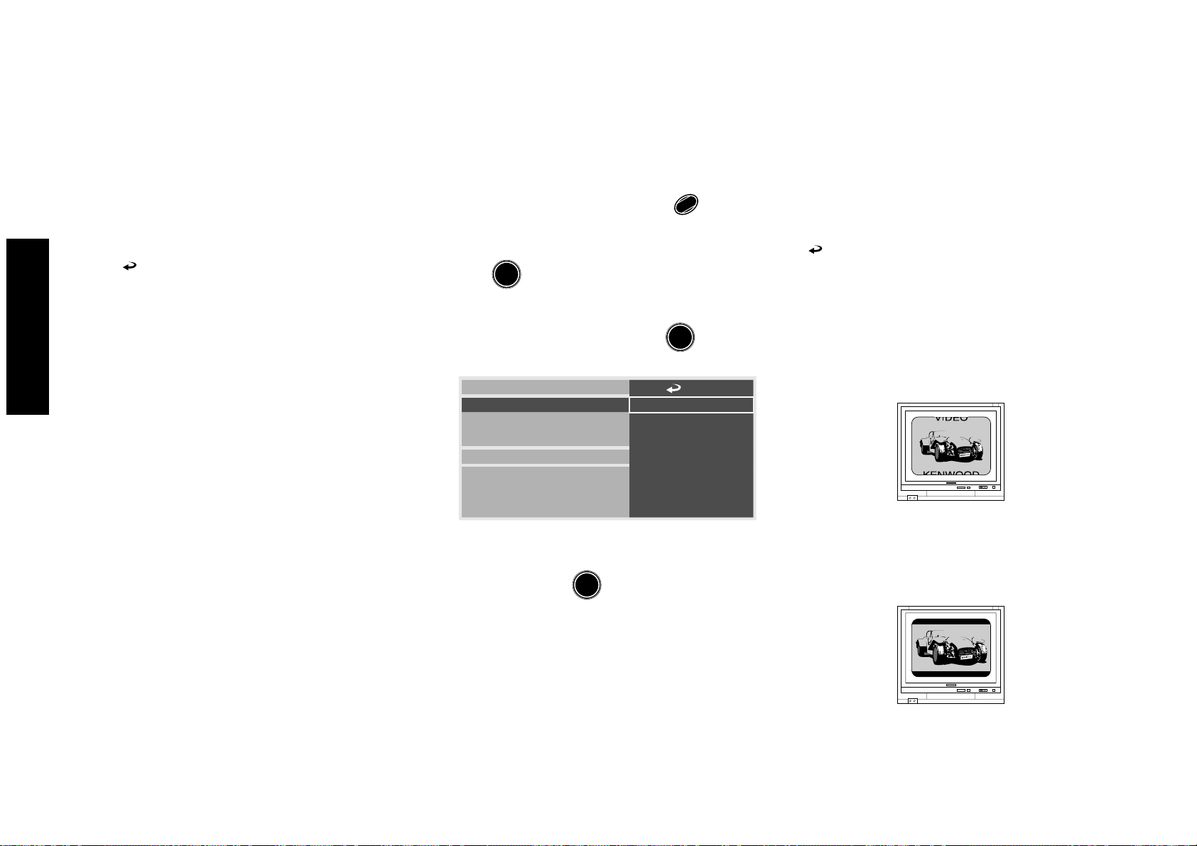
"MAIN" Setting
7
7
8 No Limit
7
7
7
6
7
5
7
4
7
3
7
2
7
1
7
0 Lock All
7
Change Password
7
Temporary Unlocked
Rating
Chapter 2: Various Setups
Settings
"Rating" Setting
This setting makes it possible to inhibit the playback
of adult DVD videodiscs that you do not want the
children to view. However, there are some discs which
carries an X-rating indication on the jacket but do not
contain recording of the viewing restriction label. With
such discs, the viewing restriction of the player is
invalid and playback cannot be inhibited.
The default setting is "Level 8" which means no
restriction. When you change the restriction level for
the first time, you will also be requested to register a
password.
Setting items
" ": Select to return to the previous screen.
"8 No Limit" : Select to enable playback of any
DVD discs whether their targets are adults,
general public or children.
"7" to "2": Select to enable playback of DVD for
general and children.
¶ This setting inhibits playback of adult-
oriented DVD.
"1": Select to play only the children-oriented DVD.
¶ This setting inhibits playback of adult- and
general-oriented DVD.
"0 Lock All": Select to inhibit any DVD. Use this
setting for example when you want to inhibit
playback of an adult-oriented DVD which does
not contain the restriction information.
"Change Password": Select to change the viewing
restriction password which has been registered
before. (This item cannot be selected unless a
password has already been registered.)
"Temporary Unlocked": Select to disable
temporarily the viewing restriction which has
been set previously. (This item cannot be selected
unless a password has been set previously.)
Operation procedure
Set the mode switch of the joystick remote to the
1.
Purple position.
2. While the player is in stop mode, press
1
SET UP
to
display the "MAIN" menu of "SET UP MENU".
3. Press
ENTER
to open the setup screen.
4. In the setup menu, select "Rating" by tilting the
joystick up or down and press
ENTER
.
18
5. Select a viewing level by tilting the joystick up or
down, then press
input screen.
¶ See "Input of Password".
ENTER
to display the password
Page 19

Input of Password
Chapter 2: Various Setups
When no password has been set previously:
1 In step 5, the password input screen as shown
below appears. Now, set the mode switch of the
joystick remote to the Orange position, compose
the password using the numeric buttons and
press the ENTER button.
Rating
7 Cange Level
Input a 4-digit password.
Then press ENTER.
7
----
¶ When " " in the screen is selected and the
ENTER button is pressed, the display returns to
the setting screen. (This effect can also be
achieved by pressing the RETURN button or
tilting the joystick toward the left.)
2 The password input screen changes to the con-
firmation screen, and the input password is
shown on the TV screen.
Rating
The player is locked.
Please remember the password.
Press ENTER to continue.
When a password has already been set:
In step 5, the password input screen as shown
below appears. Now set the mode switch of the
joystick remote to the Orange position, input the
password using the numeric buttons and press
the ENTER button.
Rating
7 Cange Level
Input a 4-digit password.
Then press ENTER.
7
----
¶ When " " in the screen is selected and the
ENTER button is pressed, the display returns to
the setting screen. (This effect can also be
achieved by pressing the RETURN button or
tilting the joystick toward the left.)
If you select "Change Password", the screen for
input of the new password will open. Input the new
password using the numeric buttons and press the
ENTER button. When the password confirmation
screen appears, note the password in a memo and
retain it in a safe place then pressing the ENTER
button.
Settings
0214
3 Note the password in a memo and retain it in a
safe place before pressing the ENTER button. The
password is required when setting the viewing
restriction.
19
Page 20
Chapter 2: Various Setups
Settings
"TV Aspect" Setting
If the connected TV is a widescreen TV, set the aspect
ratio (the ration between the horizontal and vertical
sizes of TV screen) of the player output to 16:9.
The player has been set to a the conventional aspect
ratio of "4:3" before it was shipped from the factory.
Setting items
" " : Select to return to the previous screen.
"4 : 3" : Select when the connected TV uses the
conventional aspect ratio of 4:3.
"16 : 9" : Select when the connected TV uses the
wide-screen aspect ratio of 16:9. Widescreen
video will be reproduced in full screen. (Set the
screen mode of the TV to the full mode.)
Operation procedure
Set the mode switch of the joystick remote to the
1.
Purple position.
2. While the player is in stop mode, press
1
to display
SET UP
the "MAIN" menu of "SET UP MENU".
3. Press
ENTER
to open the setup screen.
4. In the setup menu, select "TV Aspect" by tilting
7
7
4:3
7
16:9
ENTER
.
the joystick up or down and press
Rating
TV Aspect
TV Mode
TV Monitor Type
DVD VIDEO Mode
OSD Position
On Screen Message
IPB Display
5. Select an aspect ratio by tilting the joystick up or
down, then press
ENTER
to enter the selection in
"TV Mode" Setting
When the connected TV has a 4:3 aspect ratio while
the played software is recorded in widescreen video,
the mode of TV screen display can be selected.
At the factory, the player has been set to "Letterbox".
Setting items
" " : Select to return to the previous screen.
"Pan & Scan" : Select to play widescreen software
with pan & scan specification on a pan & scan
screen (screen with the left and/or right edges
cut off). When widescreen software without pan
& scan specification is played with this setting,
it will be reproduced in the Letterbox screen
mode. e
"Letterbox" : Widescreen software without pan &
scan specification is reproduced in the Letterbox
screen (screen with black bands on the top and
bottom). e
20
memory.
Page 21

"TV Monitor Type" Setting
Chapter 2: Various Setups
Operation procedure
Set the mode switch of the joystick remote to the
1.
Purple position.
2. While the player is in stop mode, press
SET UP
1
to
display the "MAIN" menu of "SET UP MENU".
3. Press
ENTER
to open the setup screen.
4. In the setup menu, select "TV Mode" by tilting the
joystick up or down and press
Rating
TV Aspect
TV Mode
TV Monitor Type
DVD VIDEO Mode
OSD Position
On Screen Message
IPB Display
ENTER
.
7
7
Pan & Scan
7
Letterbox
This setting adjusts the picture quality according to
the type of the connected TV. If you use a means of
display other than ordinary CRT TV, such as a video
monitor or projector, you can adjust this setting
according to your taste.
At the factory, the player has been set to "Standard"
for using a CRT-based TV.
Setting items
" : Select to return to the previous screen.
"
"Standard" : Select when connecting a CRT-based
TV. Usually select this item.
"CRT Projector" : Select when connecting a 3-tube
front projector.
"LCD Projector" : Select when connecting a LCD
front projector.
"Projection TV" : Select when connecting a
projection TV.
"PDP" : Select when connecting a plasma display
panel.
Operation procedure
Set the mode switch of the joystick remote to the
1.
Purple position.
2. While the player is in stop mode, press
1
SET UP
to
display the "MAIN" menu of "SET UP MENU".
3. Press
ENTER
to open the setup screen.
4. In the setup menu, select "TV Monitor Type" by
tilting the joystick up or down and press
Rating
TV Aspect
TV Mode
TV Monitor Type
DVD VIDEO Mode
OSD Position
On Screen Message
IPB Display
7
7
Standard
7
CRT Projector
7
LCD Projector
7
Projection TV
7
PDP
ENTER
.
Settings
5. Select a TV screen mode by tilting the joystick up
or down, then press
memory.
ENTER
to enter the selection in
5. Select a monitor type by tilting the joystick up or
down, and press
memory.
ENTER
to enter the selection in
21
Page 22

Chapter 2: Various Setups
Settings
"DVD VIDEO Mode" Setting
When playing a disc in which DVD VIDEO and DVD
AUDIO are mixed, this setting makes it possible to
select whether the DVD VIDEO part or DVD AUDIO
part is to be played. To reproduce only the DVD VIDEO
part, set this item to "On".
At the factory, the player has been set to "Off" with
which the DVD AUDIO part is played back.
Setting items
" " : Select to return to the previous screen.
"On" : Select to play only the DVD VIDEO part in
a DVD VIDEO/DVD AUDIO mixed disc.
"Off" : Select to pay only the DVD AUDIO part in
a DVD VIDEO/DVD AUDIO mixed disc.
Operation procedure
Set the mode switch of the joystick remote to the
1.
Purple position.
2. While the player is in stop mode, press
1
SET UP
to
display the "MAIN" menu of "SET UP MENU".
3. Press
ENTER
to open the setup screen.
4. In the setup menu, select "DVD VIDEO Mode" by
ENTER
tilting the joystick up or down and press
7
7
7
On
Off
Rating
TV Aspect
TV Mode
TV Monitor Type
DVD VIDEO Mode
OSD Position
On Screen Message
IPB Display
.
"OSD Position" Setting
When the connected TV is a widescreen TV, the OSD
(On-Screen Display) or on-screen messages may be
displayed incorrectly or overflow outside the screen
depending on the TV screen mode setting. The OSD
position switching makes it possible to display the
OSD and on-screen messages normally.
At the factory, the player has been set to "Normal".
Setting items
" " : Select to return to the previous screen.
"Normal" : Select to display the OSD and messages
on the top of the TV screen. Usually select this
setting.
"Cinema" : Select to display the OSD and messages
on the lower part of the TV screen. Select this
setting when the OSD or messages are deviated
outside the TV screen.
22
5. Select "On" or "Off" by tilting the joystick up or
down, then press
memory.
¶ This setting is reset to default "Off" when the
disc is changed or the power is set to off or
standby.
ENTER
to enter the selection in
Page 23

"On Screen Message" Setting
Chapter 2: Various Setups
Operation procedure
Set the mode switch of the joystick remote to the
1.
Purple position.
2. While the player is in stop mode, press
SET UP
1
to
display the "MAIN" menu of "SET UP MENU".
3. Press
ENTER
to open the setup screen.
4. In the setup menu, select "OSD Position" by tilting
7
7
7
Normal
7
Cinema
ENTER
.
the joystick up or down and press
Rating
TV Aspect
TV Mode
TV Monitor Type
DVD VIDEO Mode
OSD Position
On Screen Message
IPB Display
This setting makes it possible to enable or display of
on-screen messages which notifies the user of various
information.
At the factory, the player has been set to "On" for
displaying on-screen messages.
Setting items
" " : Select to return to the previous screen.
"On" : Select to display on-screen messages.
"Off" : Select to not to display on-screen messages.
Operation procedure
Set the mode switch of the joystick remote to the
1.
Purple position.
2. While the player is in stop mode, press
1
SET UP
to
display the "MAIN" menu of "SET UP MENU".
3. Press
ENTER
to open the setup screen.
4. In the setup menu, select "On Screen Message"
by tilting the joystick up or down and press
7
7
Rating
TV Aspect
TV Mode
TV Monitor Type
DVD VIDEO Mode
OSD Position
On Screen Message
IPB Display
7
On
7
Off
ENTER
Settings
.
5. Select the OSD position by tilting the joystick up
or down, then press
memory.
ENTER
to enter the selection in
5. Select "On" or "Off" by tilting the joystick up or
down, then press
memory.
ENTER
to enter the selection in
23
Page 24

"IPB Display" Setting
Chapter 2: Various Setups
Settings
With the MPEG2 which is one of the video display
methods of DVD, each picture is divided into the
following three picture types before being coded in
digital signal.
I-picture (in-frame coding): This is the standard
video and can constitute a picture by itself. As the
highest picture quality can be obtained, the still
image of I-picture is most suitable for use when
adjusting the picture quality.
P-picture (forward prediction coding): Picture cal-
culated based on past pictures (I-picture or P-picture).
B-picture (bidirectional prediction coding): Pic-
ture calculated by comparing the previous and next
pictures (I-pictures or P-pictures). This picture type
contains least amount of video information.
When IPB Display is set to "On", the I, P or B type of
DVD still picture is displayed on the TV screen to help
identify whether the picture is I-picture, P-picture or
B-picture. This makes it possible to find the I-picture
which is the standard video containing most amount
of information.
At the factory, the player has been set to "Off" with
which the IPB display is not shown.
Operation procedure
Set the mode switch of the joystick remote to the
1.
Purple position.
2. While the player is in stop mode, press
1
SET UP
to
display the "MAIN" menu of "SET UP MENU".
3. Press
ENTER
to open the setup screen.
4. In the setup menu, select "IPB Display" by tilting
7
7
7
On
Off
ENTER
.
the joystick up or down and press
Rating
TV Aspect
TV Mode
TV Monitor Type
DVD VIDEO Mode
OSD Position
On Screen Message
IPB Display
5. Select "On" or "Off" by tilting the joystick up or
ENTER
down, then press
to enter the selection in
Setting items
" " : Select to return to the previous screen.
"On" : Select to view the IPB display.
"Off" : Select to not to view the IPB display.
24
memory.
Page 25

MEMORANDUM
Chapter 2: Various Setups
Settings
25
Page 26

"SOUND" Setting
Chapter 2: Various Setups
Settings
"Digital Audio PCM Down Conversion" Setting
The player can output digital signal with maximum
sampling rate of 96 kHz from the digital audio output
connector. When a DVD disc recorded in high
sampling rate PCM is played, this setting makes it
possible to select whether the signal is converted into
48 kHz signal or 44.1 kHz/16-bit signal.
At the factory, the player has been set to "On" for AV
amplifiers incompatible with high sampling rate
digital signal connection. If the connected AV amplifier
is compatible with 96 kHz digital input, change the
setting to "Off".
Setting items
" " : Select to return to the previous screen.
"On" : Select to down-convert the signal to 44.1
kHz/16-bit PCM signal. Select this setting when
the connected AV amplifier is incompatible with
96 kHz digital input.
¶ The analog output signals are also converted
accordingly.
"Off" : Select to skip down conversion. Select this
setting when the connected AV amplifier is
compatible with 96 kHz digital input. However,
if the disc inhibits the 96 kHz digital output,
the signal is down-converted even when this
setting is selected.
Operation procedure
Set the mode switch of the joystick remote to the
1.
Purple position.
2. While the player is in stop mode, press
1
SET UP
and
tilt the joystick up or down to display the "SOUND"
menu of "SET UP MENU".
3. Press
ENTER
to open the setup screen.
4. In the setup menu, select "Digital Audio PCM
Down Conversion" by tilting the joystick up or
down and press
Digital Audio
PCM Down Conversion
Dolby Digital
DTS
MPEG
Speaker Setting
Audio During Search
Dynamic Range Control
Audio Filter
ENTER
.
7
7
On
7
Off
"Digital Audio Dolby Digital" Setting
When a DVD recorded in Dolby Digital is played, this
setting makes it possible to select the audio signal from
the digital output connector of the player.
At the factory, the player has been set to "Bitstream" to
enable digital connection to an AV amplifier with builtin Dolby Digital decoder. Change the setting to "PCM"
when the digitally connected amplifier does not
incorporate the decoder.
Setting items
"
" : Select to return to the previous screen.
"Bitstream" : The signal is output as a bitstream.
Select when connecting a component containing
Dolby Digital decoder.
"PCM" : The signal is converted onto 48 kHz
(2CH.) PCM signal before being output. Select
when connecting a component without Dolby
Digital decoder.
26
¶ With DVD AUDIO discs, the signal is always
output after down sampling conversion.
5. Select "On" or "Off" by tilting the joystick up or
ENTER
down, then press
memory.
to enter the selection in
Page 27

"Digital Audio DTS" Setting
Chapter 2: Various Setups
Operation procedure
Set the mode switch of the joystick remote to the
1.
Purple position.
2. While the player is in stop mode, press
tilt the joystick up or down to display the "SOUND"
menu of "SET UP MENU".
3. Press
ê›Å@íËÅ@ï“
4. In the setup menu, select "Digital Audio Dolby
Digital" by tilting the joystick up or down and
press
ENTER
to open the setup menu.
ENTER
.
Digital Audio
PCM Down Conversion
Dolby Digital
DTS
MPEG
Speaker Setting
Audio During Search
Dynamic Range Control
Audio Filter
7
7
Bitstream
7
PCM
1
SET UP
and
When a DVD or DTS-CD recorded in DTS is played,
this setting makes it possible to select the audio signal
output from the digital output connector.
At the factory, the player has been set to "Bitstream"
to enable digital connection to an AV amplifier with
built-in DTS decoder. Change the setting to "PCM"
when the digitally connected amplifier does not
incorporate the decoder.
Setting items
" : Select to return to the previous screen.
"
"Bitstream" : The signal is output as a bitstream.
Select when connecting a component containing
DTS decoder.
"PCM" : The signal is converted onto 48 kHz
(2CH.) PCM signal before being output. Select
when connecting a component without DTS
decoder.
Operation procedure
Set the mode switch of the joystick remote to the
1.
Purple position.
2. While the player is in stop mode, press
SET UP
1
and
tilt the joystick up or down to display the "SOUND"
menu of "SET UP MENU".
3. Press
ENTER
to open the setup screen.
4. In the setup menu, select "Digital Audio DTS" by
tilting the joystick up or down and press
7
Digital Audio
PCM Down Conversion
Dolby Digital
DTS
MPEG
Speaker Setting
Audio During Search
Dynamic Range Control
Audio Filter
7
Bitstream
7
PCM
ENTER
.
5. Select the audio output by tilting the joystick up or
Settings
5. Select the audio output by tilting the joystick up or
down, and press
memory.
ENTER
to enter the selection in
down, and press
memory.
ENTER
to enter the selection in
27
Page 28

Chapter 2: Various Setups
Settings
"Digital Audio MPEG" Setting
When a DVD recorded in MPEG Audio is played, this
setting makes it possible to select the audio signal
output from the digital output connector.
At the factory, the player has been set to "Bitstream"
to enable digital connection to an AV amplifier with
built-in MPEG decoder. Change the setting to "PCM"
when the digitally connected amplifier does not
incorporate the decoder.
Setting items
" " : Select to return to the previous screen.
"Bitstream" : The signal is output as a bitstream.
Select when connecting a component containing
MPEG decoder.
"PCM" : The signal is converted onto 48 kHz (2CH)
PCM signal before being output. Select when
connecting a component without MPEG
decoder.
Operation procedure
Set the mode switch of the joystick remote to the
1.
Purple position.
2. While the player is in stop mode, press
1
SET UP
and
tilt the joystick up or down to display the "SOUND"
menu of "SET UP MENU".
3. Press
ENTER
to open the setup screen.
4. In the setup menu, select "Digital Audio MPEG"
by tilting the joystick up or down and press
7
Digital Audio
PCM Down Conversion
Dolby Digital
DTS
MPEG
Speaker Setting
Audio During Search
Dynamic Range Control
Audio Filter
7
Bitstream
7
PCM
ENTER
"Speaker Setting"
When an associated system component is connected
to the 6CH. OUTPUT jacks of the player, this setting
is required on the player.
At the factory, the player has been set to the standard
setting with which the speakers can reproduce the 6channel signals as soon as the connections are made.
This setting can be changed according to each listening
environment. When you want to change this setting,
be sure to perform it in the listening area in your own
listening environment.
¶ For the "Speaker Setting" when an AV amplifier
is connected digitally to the player, refer to the
instruction manual of the AV amplifier.
.
Front speakers (L, R)
Size: "Large"
Center speaker (C)
Size: "Large"
Use of center speaker: Used
Level: "0 dB"
Delay time: "0 ms"
Surround speakers (LS, RS)
Size: "Large"
28
5. Select the audio output by tilting the joystick up or
ENTER
down, and press
memory.
to enter the selection in
Use of surround speakers: Used
Level: "0 dB"
Delay time: "0 ms"
Subwoofer
Use of subwoofer: Used
Level: "0 dB"
Page 29
Chapter 2: Various Setups
0 dB
0 dB
0 ms
0 ms 0 dB0 dB
LS
R
RS
L
SW
C
L R
Speaker Setting
Exit
Size
Normal
Large
Operation procedure
Set the mode switch of the joystick remote to the
1.
Purple position.
2. While the player is in stop mode, press
tilt the joystick up or down to display the "SOUND"
menu of "SET UP MENU".
3. Press
ê›Å@íËÅ@ï“
4. In the setup menu, select "Speaker Setting" by
tilting the joystick up or down and press
ENTER
to open the setup screen.
1
SET UP
ENTER
and
.
5. Set each speaker by tilting the joystick up/down
and to the left/right. Select the item to be set and
ENTER
press
Speaker Setting
LS
To set the front speakers: Select and adjust either
"L" or "R". The other, non-selected front speaker
will automatically set to the same setting as the
selected speaker.
To set the center speaker: Select "C".
To set the surround speakers: Select and adjust
"LS" and "RS" separately.
To set the subwoofer: Select "SW".
To output the test tone: Select "Test"
.
Test
L
0 dB
SW
Exit
CSWR
L
RSLS
0 dB
C
0 ms
0 ms 0 dB0 dB
R
RS
6. Select the desired speaker setting by tilting the joy-
stick up/down and to the left/right.
" is selected, the screen in step 5 appears again
If "
without entering the performed changes in the
speaker setting in memory.
[Front Seakers setting]
Size: Select "Normal" when the connected speaker
is incapable of reproducing audio below 100 Hz.
Select "Large" when the connected speaker can
reproduce audio below 100 Hz.
After completing the speaker setting, select "Exit"
to enter the setting and return to the screen in
step 5.
Settings
To exit from the screen: Select "Exit"
29
Page 30
Chapter 2: Various Setups
0 dB
dB
0 dB
0 ms
Speaker Setting
0 ms 0 dB0 dB
-6 -5 -4 -3 -2 -1 0 +1 +2 +3 +4 +5 +6
ms
01.3
2.6
3.9 5.3
LS
R
RS
L
SW
C
C
Level
Delay Time
Exit
Off
Size
Normal
Large
Settings
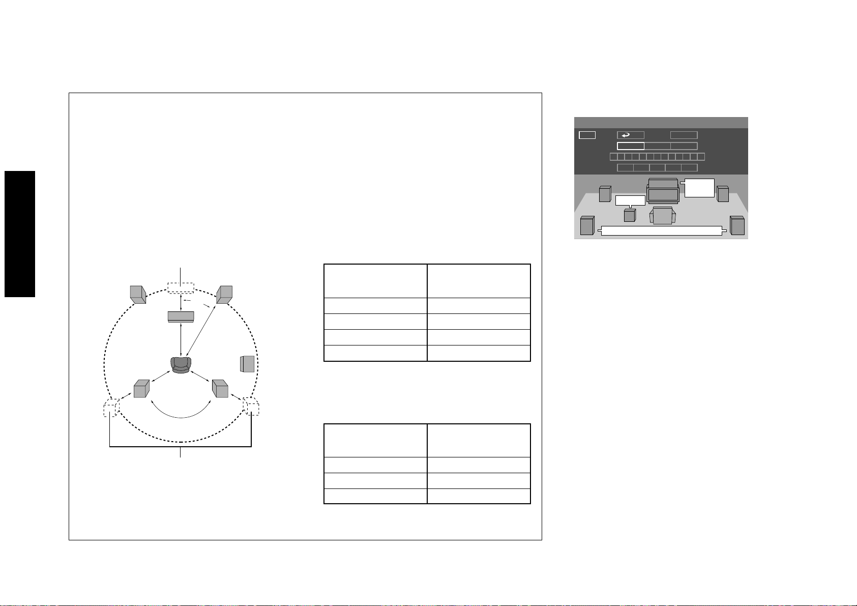
Delay Time Setting
When playing a DVD recorded with Dolby Digital audio, the distances from the listening position to the
center and surround speakers should ideally be identical to those of all other speakers except for the
subwoofer. The delay time setting makes it possible to compensate for the difference in distances of actual
speakers by delaying the audio output from the center speaker and surround speakers so that the sounds
from all speakers reach the listening position at the same timing. (The delay time adjustment is available
only with Dolby Digital.)
Before starting the speaker setting, see the following figure and measure distance A of the center speaker
(A = Df - Dc) and distance B for the surround speakers (B = Df - Ds). The standard delay time settings can
be identified based on these values and the following tables.
Ideal center speaker position
L R
30°
A
C
Dc
Df
Ds
LS RS
120°
SW
B
Delay time of center speaker
Distance A
(A = Df - Dc)
Setting Value
Approx. 50 cm "1.3" ms
Approx. 100 cm "2.6" ms
Approx. 150 cm "3.9" ms
Approx. 200 cm "5.3" ms
¶ If distance Df is equal to or shorter than
Dc, set to "0".
Delay time of surround speakers
[Center speaker setting]
Size: Select "Normal" when the connected speaker
is incapable of reproducing audio below 100 Hz.
Select "Large" when the connected speaker can
reproduce audio below 100 Hz.
Use of center speaker: Select "Off" if the center
speaker is not used.
Level: Set the volume level.
Delay Time: Set the delay time. For the setting
value, see "Delay Time Setting".
After completing the speaker setting, select "Exit"
to enter the setting and return to the screen in
step 5.
30
Ideal surround speaker positions
¶ All speakers should be laid out within a circle
as shown in the figure.
Distance B
(B = Df - Ds)
Setting Value
Approx. 200 cm "5.3" ms
Approx. 400 cm "10.6" ms
Approx. 600 cm "15.9" ms
¶ If distance Df is equal to or shorter than
Ds, set to "0".
Page 31

Chapter 2: Various Setups
[Surround speakers setting]
Speaker Setting
Size
Level
Delay Time
Size: Select "Normal" when the connected speaker
ê›Å@íËÅ@ï“
Use of surround speaker: Select "Off" if the
Level: Set the volume level.
Delay Time: Set the delay time. For the setting
After completing the speaker setting, select "Exit"
to enter the setting and return to the screen in
step 5.
Normal
10.6
0 ms 0 dB0 dB
Exit
Off
15.9
C
ms
0 dB
0 ms
dB
R
RS
LS
Large
-6 -5 -4 -3 -2 -1 0 +1 +2 +3 +4 +5 +6
05.3
L
0 dB
SW
LS
is incapable of reproducing audio below 100 Hz.
Select "Large" when the connected speaker can
reproduce audio below 100 Hz.
surround speaker is not used.
value, see "Delay Time Setting".
[Subwoofer setting]
Speaker Setting
SW
Size
Level
LS
On
-5 -4 -3 -2 -1 +1 +2 +3 +4 +5 +6
-6 0
L
0 dB
SW
Exit
Off
dB
0 dB
C
0 ms
0 ms 0 dB0 dB
R
RS
Use of subwoofer: Select "Off" if the subwoofer
is not used.
Level: Set the volume level.
After completing the speaker setting, select "Exit"
to enter the setting and return to the screen in
step 5.
7. After completing the speaker settings, select "Test"
by tilting the joystick up/down or to the left/right
ENTER
and press
across the speakers in sequence from "L" and the
test tone is output from each speaker indicated by
the cursor.
ENTER
Press
screen for the speaker being indicated by the cursor.
¶ The cursor skips the subwoofer and the speakers
set to "Off" and test tone is not output from
them.
¶ After adjusting the level of each speaker channel
by tilting the joystick to the left or right, press
the ENTER button, then select "Exit" and press
the ENTER button to restart the test tone output.
Repeat the volume level adjustment until the
volumes of all speakers are identical.
¶ When the joystick is tilted in any direction during
the test tone output, the test tone output stops.
(The same effect can also be obtained by pressing
the RETURN button)
. The cursor will automatically move
again to display the speaker setting
Settings
8. After completing the speaker setting, select "Exit"
and press
¶ As the test tone is not output from the subwoofer,
its volume level should be adjusted after listening
to the actual sound.
ENTER
to enter the setting in memory.
31
Page 32

Chapter 2: Various Setups
Settings
"Audio During Search" Setting
During DVD or VCD search at the first speed step, this
setting makes it possible to select whether the
reproduced audio is output or not.
At the factory, the player has been set to "On" for
outputting the reproduced audio during search.
Setting items
" " : Select to return to the previous screen.
"On" : Select to output audio during search.
"Off" : Select to mute audio during search.
Operation procedure
Set the mode switch of the joystick remote to the
1.
Purple position.
2. While the player is in stop mode, press
1
SET UP
and
tilt the joystick up or down to display the "SOUND"
menu of "SET UP MENU".
3. Press
ENTER
to open the setup screen.
4. In the setup menu, select "Audio During Search"
by tilting the joystick up or down and press
7
Digital Audio
PCM Down Conversion
Dolby Digital
DTS
MPEG
Speaker Setting
Audio During Search
Dynamic Range Control
Audio Filter
7
On
7
Off
ENTER
"Dynamic Range Control" Setting
When playing a DVD recorded with Dolby Digital
Surround, set the dynamic range control according to
the software being played. For instance, when the
words are hard to be listened to due to effects sound
in a move, this setting makes it possible to adjust the
volume level of only the low-level sound and can
reduce repetition of complicated volume level
adjustments.
At the factory, the player has been set to "Wide" with
which the audio levels recorded in discs are reproduced
as they are.
.
Setting items
" " : Select to return to the previous screen.
"Wide" : Select to reproduced the audio at the level
recorded in the disc.
"Normal" : Select to reduce the difference between
the maximum and minimum volume levels.
"Midnight" : Select to further reduce the difference
between the maximum and minimum volume
levels. This setting is suitable for low-level
listening in late at night, etc.
32
5. Select "On" or "Off" by tilting the joystick up or
ENTER
down, then press
memory.
to enter the selection in
Page 33

"Audio Filter" Setting
Chapter 2: Various Setups
Operation procedure
Set the mode switch of the joystick remote to the
1.
Purple position.
2. While the player is in stop mode, press
tilt the joystick up or down to display the "SOUND"
menu of "SET UP MENU".
3. Press
ê›Å@íËÅ@ï“
4. In the setup menu, select "Dynamic Range
Control" by tilting the joystick up or down and
press
5. Select the level by tilting the joystick up or down,
then press
ENTER
to open the setup screen.
ENTER
.
Digital Audio
PCM Down Conversion
Dolby Digital
DTS
MPEG
Speaker Setting
Audio During Search
Dynamic Range Control
Audio Filter
ENTER
to enter the selection in memory.
7
7
Wide
7
Normal
7
Midnight
1
SET UP
and
DVD AUDIO is recorded with a maximum sampling
rate of 192 kHz and theoretically capable of
reproducing up to 96 kHz. As a result, the speakers
used may be damaged if they are not compatible with
high frequencies. When an ordinary speaker system is
connected, set the "Audio Filter" setting to "Filter
60 kHz" to protect the speakers. When the speaker in
use are compatible with high frequencies, set this
setting to "Filter 110 kHz". (For details, refer to the
instruction manuals provided with your speakers.)
At the factory, the player has been set to "Filter 60
kHz" to protect the speakers from damage.
Setting items
" : Select to return to the previous screen.
"
"Filter 60 kHz" : Select when the speakers in use
are not suitable for reproduction of high
frequencies.
"Filter 110 kHz" : Select when the speakers in use
are suitable for reproduction of high frequencies.
Operation procedure
Set the mode switch of the joystick remote to the
1.
Purple position.
2. While the player is in stop mode, press
SET UP
1
and
tilt the joystick up or down to display the "SOUND"
menu of "SET UP MENU".
3. Press
ENTER
to open the setup screen.
4. In the setup menu, select "Audio Filter" by tilting
ENTER
the joystick up or down and press
7
Digital Audio
PCM Down Conversion
Dolby Digital
DTS
MPEG
Speaker Setting
Audio During Search
Dynamic Range Control
Audio Filter
7
Filter 60kHz
7
Filter 110kHz
.
5. Select "Filter 60 kHz" or "Filter 110 kHz" by tilting
the joystick up or down, then press
the selection in memory.
ENTER
to enter
Settings
33
Page 34

"VISUAL" Setting
Chapter 2: Various Setups
Settings
"Player Menu Language" Setting
This setting makes it possible to select the language
used to display the menus of the player.
At the factory, the language used in displaying the
menus of the player has been set to "English".
Setting items
"
" : Select to return to the previous screen.
"English" : Select to display menus in English.
"French" : Select to display menus in French.
"Spanish" : Select to display menus in Spanish.
"German" : Select to display menus in German.
"Italian" : Select to display menus in Italian.
"Japanese" : Select to display menus in Japanese.
"Chinese" : Select to display menus in Chinese.
"Taiwanese" : Select to display menus in traditional
Chinese letters.
Operation procedure
Set the mode switch of the joystick remote to the
1.
Purple position.
2. While the player is in stop mode, press
1
SET UP
and
tilt the joystick up or down to display the "VISUAL"
menu of "SET UP MENU".
3. Press
ENTER
to open the setup screen.
4. In the setup menu, select "Player Menu Language"
by tilting the joystick up or down and press
7
Player Menu Language
Disc Menu Language
Audio Language
Subtitle Language
Still Mode
FL Mode
NTSC = PAL
SCART Output Select
7
English
7
French
7
Spanish
7
German
7
Italian
7
Japanese
7
Chinese
7
Taiwanese
ENTER
"Disc Menu Language" Setting
This setting makes it possible to select the language
used to display the menus recorded in discs. (If the
selected language is not used in a specific disc, the
language specified as the priority language for the disc
will be used.)
At the factory, the language used in displaying the
menus of the disc has been set to "English".
Setting items
" : Select to return to the previous screen.
"
"English" : Select to display menus in English.
"French" : Select to display menus in French.
.
"Spanish" : Select to display menus in Spanish.
"German" : Select to display menus in German.
"Italian" : Select to display menus in Italian.
"Chinese" : Select to display menus in Chinese.
"Other
----
" : Select to specify the language
using a code No. listed in the "Disc Language
Code Table". ‚
¶ The languages displayed with this setting item
are variable depending on country and area.
34
5. Select the language by tilting the joystick up or
ENTER
down, then press
memory.
to enter the selection in
Operation procedure
Set the mode switch of the joystick remote to the
1.
Purple position.
2. While the player is in stop mode, press
tilt the joystick up or down to display the "VISUAL"
menu of "SET UP MENU".
SET UP
1
and
Page 35

"Audio Language" Setting
7
Other
- - - -
7
Disc Menu Language
Audio Language
Subtitle Language
Still Mode
FL Mode
SCART Output Select
NTSC = PAL
Player Menu Language
7
Italian
7
Spanish
7
French
7
German
7
Original
7
English
Chapter 2: Various Setups
3. Press
4. In the setup menu, select "Disc Menu Language"
by tilting the joystick up or down and press
5. Select the language by tilting the joystick up or
down, then press
memory.
¶ When "Other
¶ If you make a mistake when pressing numeric
ENTER
to open the setup screen.
ENTER
Player Menu Language
Disc Menu Language
Audio Language
Subtitle Language
Still Mode
FL Mode
NTSC = PAL
SCART Output Select
ENTER
----
7
7
English
7
French
7
Spanish
7
German
7
Italian
7
Other
- - - -
to enter the selection in
"is selected, set the mode
switch of the joystick remote to the Orange
position, input the desired code No. using the
numeric keys and press the ENTER button.
keys, press the C button and restart the code No.
input from the beginning.
This setting makes it possible to select the language
used to reproduce the audio recorded in the disc in
the desired language. (If the selected language is not
used in a specific disc, the language specified as the
.
priority language for the disc will be used.)
At the factory, the audio language has been set to
"English".
Setting items
" : Select to return to the previous screen.
"
"Original" : Select to reproduce audio in the
language specified as the priority language by
the disc.
"English" : Select to display menus in English.
"French" : Select to display menus in French.
"Spanish" : Select to display menus in Spanish.
"German" : Select to display menus in German.
"Italian" : Select to display menus in Italian.
"Chinese" : Select to display menus in Chinese.
"Other
----
" : Select to specify the language
using a code No. listed in the "Disc Language
Code Table". ‚
¶ The languages displayed with this setting item
are variable depending on country and area.
Operation procedure
Set the mode switch of the joystick remote to the
1.
Purple position.
2. While the player is in stop mode, press
SET UP
1
and
tilt the joystick up or down to display the "VISUAL"
menu of "SET UP MENU".
3. Press
ENTER
to open the setup screen.
4. In the setup menu, select "Audio Language" by
ENTER
tilting the joystick up or down and press
.
5. Select the desired audio language by tilting the
ENTER
joystick up or down, then press
selection in memory.
¶ When "Other
----
"is selected, set the mode
switch of the joystick remote to the Orange
position, input the desired code No. using the
numeric keys and press the ENTER button.
¶ If you make a mistake when pressing numeric
keys, press the C button and restart the code No.
input from the beginning.
to enter the
Settings
35
Page 36

Chapter 2: Various Setups
Settings
"Subtitle Language" Setting
This setting makes it possible to select the language
used to display the subtitles recorded in discs. (When
the disc does not contain the recording of the selected
subtitle language, the default subtitle language defined
for the disc will be used.)
At the factory, the language used in displaying the
subtitles has been set to "English".
Setting items
" : Select to return to the previous screen.
"
"Auto" : The subtitle language is selected automatically
according to the "Audio language" setting.
Case in which subtitles are not displayed: When
the voices are reproduced in the language
selected with "Audio language", the subtitles
are not displayed.
Case in which subtitles are displayed: When
the voices cannot be reproduced in the
language selected with "Audio language",
subtitles are displayed in the language selected
with "Audio language".
"English" : Select to display menus in English.
"French" : Select to display menus in French.
"Spanish" : Select to display menus in Spanish.
"German" : Select to display menus in German.
"Italian" : Select to display menus in Italian.
"Chinese" : Select to display menus in Chinese.
"Other
----
using a code No. listed in the "Disc Language
Code Table". ‚
¶ The languages displayed with this setting item
are variable depending on country and area.
" : Select to specify the language
Operation procedure
Set the mode switch of the joystick remote to the
1.
Purple position.
2. While the player is in stop mode, press
1
SET UP
and
tilt the joystick up or down to display the "VISUAL"
menu of "SET UP MENU".
3. Press
ENTER
to open the setup screen.
4. In the setup menu, select "Subtitle Language" by
ENTER
tilting the joystick up or down and press
7
Player Menu Language
Disc Menu Language
Audio Language
Subtitle Language
Still Mode
FL Mode
NTSC = PAL
SCART Output Select
7
Auto
7
English
7
French
7
Spanish
7
German
7
Italian
7
Other
- - - -
.
5. Select the desired subtitle language by tilting the
ENTER
joystick up or down, then press
selection in memory.
¶ When "Other
----
"is selected, set the mode
switch of the joystick remote to the Orange
position, input the desired code No. using the
numeric keys and press the ENTER button.
to enter the
"Still Mode" Setting
This setting makes it possible to reduce blur in still
pictures automatically. In addition, it also allows you
to select the frame still or field still picture.
At the factory, the player has been set to "Auto", with
which frame still and field still pictures are switched
automatically.
Setting items
" : Select to return to the previous screen.
"
"Auto" : Frame still and field still pictures are
switched automatically. Usually select this
setting.
"Frame" : Select to display still pictures in a higher
picture quality. (As the field and still pictures are
displayed alternately, the picture may blur
accordingly.)
"Field" : Select to display still pictures without blur.
(As the video information is halved compared
to the frame pictures, the picture quality
deteriorates accordingly.)
36
¶ If you make a mistake when pressing numeric
keys, press the C button and restart the code No.
input from the beginning.
Page 37

"FL Mode" Setting
7
Dimmer
7
Brightness
7
Auto Off
7
Disc Menu Language
Audio Language
Subtitle Language
Still Mode
FL Mode
SCART Output Select
NTSC = PAL
Player Menu Language
Chapter 2: Various Setups
Operation procedure
Set the mode switch of the joystick remote to the
1.
Purple position.
2. While the player is in stop mode, press
1
SET UP
and
tilt the joystick up or down to display the "VISUAL"
menu of "SET UP MENU".
3. Press
ENTER
to open the setup screen.
4. In the setup menu, select "Still Mode" by tilting
ENTER
the joystick up or down and press
Player Menu Language
Disc Menu Language
Audio Language
Subtitle Language
Still Mode
FL Mode
NTSC = PAL
SCART Output Select
7
7
Auto
7
Frame
7
Field
.
This setting makes it possible to select the brightness
of the player's display panel.
At the factory, the player has been set to "Brightness",
with which the display is permanently displayed in
high brightness.
Setting items
" : Select to return to the previous screen.
"
"Brightness" : The display is permanently in high
brightness.
"Dimmer" : The display is permanently displayed
in low brightness.
"Auto Off" : The display is disapled when playing
a DVD VIDEO or VCD. (The display is shown
when DVD AUDIO without video is played.) At
this time, the "Disc 1 to 5" indicators light in
low brightness and other indicators are off.
Operation procedure
Set the mode switch of the joystick remote to the
1.
Purple position.
2. While the player is in stop mode, press
SET UP
1
and
tilt the joystick up or down to display the "VISUAL"
menu of "SET UP MENU".
3. Press
ENTER
to open the setup screen.
4. In the setup menu, select "FL Mode" by tilting the
ENTER
joystick up or down and press
.
Settings
5. Select the desired still mode by tilting the joystick
up or down, then press
in memory.
ENTER
to enter the selection
5. Select the FL mode by tilting the joystick up or
down, then press
memory.
ENTER
to enter the selection in
37
Page 38

Chapter 2: Various Setups
Settings
"NTSC = PAL" Setting
(Except for the U.S.A. and Canada)
This setting makes it possible to play an NTSC-format
disc by converting signal into PAL format. Select "On"
when it is required to convert NTSC-format discs into
PAL signals.
Setting items
" " : Select to return to the previous screen.
"On" : Select to enable conversion from NTSC to
PAL.
"Off" : Select to disable conversion from NTSC to
PAL.
Operation procedure
Set the mode switch of the joystick remote to the
1.
Purple position.
2. While the player is in stop mode, press
1
SET UP
and
tilt the joystick up or down to display the "VISUAL"
menu of "SET UP MENU".
3. Press
ENTER
to open the setup screen.
4. In the setup menu, select "NTSC = PAL" by tilting
7
7
7
On
Off
ENTER
.
the joystick up or down and press
Player Menu Language
Disc Menu Language
Audio Language
Subtitle Language
Still Mode
FL Mode
NTSC = PAL
SCART Output Select
"SCART Output Select" Setting
(For Europe and U.K.)
This setting makes it possible to select the output
signals from the TV SCART connector of the player.
(The VCR SCART connector always outputs composite
video signals so its output signals cannot be selected.)
When the "RGB" output signals are selected with this
setting, the COMPONENT VIDEO OUTPUT jacks of
the player do not output any video signal.
At the factory, the TV SCART connector output signals
of the player has been set to "Composite".
Setting items
" " : Select to return to the previous screen.
"Composite" : Select to output composite video
signal.
"S Video" : Select to output S Video signals.
"RGB" : Select to output RGB signals.
38
5. Select "On" or "Off" by tilting the joystick up or
down, then press
memory.
ENTER
to enter the selection in
Page 39

Operation procedure
Set the mode switch of the joystick remote to the
1.
Purple position.
Chapter 2: Various Setups
2. While the player is in stop mode, press
1
SET UP
and
tilt the joystick up or down to display the "VISUAL"
menu of "SET UP MENU".
3. Press
ENTER
to open the setup screen.
4. In the setup menu, select "SCART Output Select"
by tilting the joystick up or down and press
7
Player Menu Language
Disc Menu Language
Audio Language
Subtitle Language
Still Mode
FL Mode
NTSC = PAL
SCART Output Select
7
Composite
7
S Video
7
RGB
ENTER
.
5. Select the desired output signals by tilting the
joystick up or down, then press
ENTER
to enter the
Settings
selection in memory.
39
Page 40

Disc Language Code Table
Chapter 2: Various Setups
Settings
Cord No. : Language
Afar
6565 :
Abkhazian
6566 :
Afrikaans
6570 :
Amharic
6577 :
Arabic
6582 :
Assamese
6583 :
Aymara
6588 :
Azerbaijani
6590 :
Bashkir
6665 :
Byelorussian
6669 :
Bulgarian
6671 :
Bihari
6672 :
Bengali; Bangla
6678 :
Tibetan
6679 :
Breton
6682 :
Catalan
6765 :
Corsican
6779 :
Czech
6783 :
Welsh
6789 :
Danish
6865 :
German
6869 :
Bhutani
6890 :
Greek
6976 :
English
6978 :
Esperanto
6979 :
Spanish
6983 :
Estonian
6984 :
Basque
6985 :
Persian
7065 :
Finnish
7073 :
Fiji
7074 :
Faroese
7079 :
French
7082 :
Cord No. : Language
7089 :
Frisian
7165 :
Irish
7168 :
Scots Gaelic
7176 :
Galician
7178 :
Guarani
7185 :
Gujarati
7265 :
Hausa
7273 :
Hindi
7282 :
Croatian
7285 :
Hungarian
7289 :
Armenian
7365 :
Interlingua
7378 :
Indonesian
7383 :
Icelandic
7384 :
Italian
7387 :
Hebrew
7465 :
Japanese
7473 :
Yiddish
7487 :
Javanese
7565 :
Geogian
7575 :
Kazakh
7576 :
Greenlandic
7577 :
Cambodian
7578 :
Kannada
7579 :
Korean
7583 :
Kashmiri
7585 :
Kurdish
7589 :
Kirghiz
7665 :
Latin
7678 :
Lingala
7679 :
Laothian
7684 :
Lithuanian
7686 :
Latvian; Lettish
Cord No. : Language Cord No. : Language
7771 :
Malagasy
7773 :
Maori
7775 :
Macedonian
7776 :
Malayalam
7778 :
Mongolian
7779 :
Moldavian
7782 :
Marathi
7783 :
Malay
7784 :
Maltese
7789 :
Burmese
7865 :
Nauru
7869 :
Nepali
7876 :
Dutch
7879 :
Nowegian
7982 :
Oriya
8065 :
Punjabi
8076 :
Polish
8083 :
Pashto; Pushto
8084 :
Portuguese
8185 :
Quechua
8277 :
Rhaeto-Romance
8279 :
Romanian
8285 :
Russian
8365 :
Sanskrit
8368 :
Sindhi
8372 :
Serbo-Croatian
8373 :
Singhalese
8375 :
Slovak
8376 :
Slovenian
8377 :
Samoan
8378 :
Shona
8379 :
Somali
8381 :
Albanian
8382 :
8385 :
8386 :
8387 :
8465 :
8469 :
8471 :
8472 :
8473 :
8475 :
8476 :
8479 :
8482 :
8484 :
8487 :
8575 :
8582 :
8590 :
8673 :
8679 :
8779 :
8872 :
8979 :
9072 :
9085 :
Serbian
Sundanese
Swedish
Swahili
Tamil
Telugu
Tajik
Thai
Tigrinya
Turkmen
Tagalog
Tonga
Turkish
Tatar
Twi
Ukrainian
Urdu
Uzbek
Vietnamese
Volapük
Wolof
Xhosa
Yoruda
Chinese
Zulu
40
Page 41

Chapter 3: Other Information
To Be Noted
Chapter 3: Other Information
DVF-R9030
Maintenance of the unit
When the front panel or case becomes dirty, wipe with
a soft, dry cloth. Do not use thinner, benzine, alcohol,
etc. for these agents may cause discoloration.
In regard to contact cleaner
Do not use contact cleaners because it could cause a
malfunction. Be specially careful not to use contact
cleaners containing oil, for they may deform the plastic
component.
Never play a cracked or warped disc
During playback, the disc rotates at high speed in the
player.
Therefore, to avoid danger, never use a cracked or
deformed disc or a disc repaired with tape or adhesive
agent.
Please do not use discs which are not round because
they may cause a malfunction.
Disc accessories
The disc accessories (stabilizer, protection sheet,
protection ring, etc.) which are marketed for improving
the sound quality or protecting discs as well as the
disc cleaner should not be used with this system
because they may cause malfunction.
Disc handling precautions
Handling : Hold a disc taking care not to touch the disc
surface.
Sticker
Sticky paste
Do not attach paper or tape to either the playing
side or the label side of the discs.
Cleaning : If fingerprints or foreign matter become
attached to the disc, lightly wipe the disc with a soft
cotton cloth (or similar) from the center of the disc
outwards in a radial manner.
Storage : When a disc is not to be played for a long
period of time, remove it from the player and store it
in its case.
Laboratories. “DOLBY” and the double-D symbol are trademarks
Manufactured under license from Dolby
of Dolby Laboratories. Confidential Unpublished Works. ©19921997 Dolby Laboratories. All rights reserved.
Manufactured under license from Digital Theater
Systems, Inc. US Pat. No. 5,451,942 and other worldwide patents
issues and pending. “DTS” and “DTS Digital Surround” are
trademarks of Digital Theater Systems, Inc. © 1996 Digital Theater
Systems, Inc. All rights reserved.
It is prohibited by laws to duplicate, broadcast, perform in public
or rent a disc without the permission of the copyright owners.
This product is compatible with the Macrovision type copy
protection. Some discs contain the recording of copy inhibit
signals, and the video may be disturbed when the video of such
discs is recorded onto a VCR and played back.
This product incorporates copyright protection technology that
is protected by method claims of certain U.S. patents and other
intellectual property rights owned by Macrovision Corporation
and other rights owners. Use of this copyright protection
technology must be authorized by Macrovision Corporation,
and is intended for home and other limited viewing uses only
unless otherwise authorized by Macrovision Corporation.
Reverse engineering or disassembly is prohibited.
General Knowledge
41
Page 42

Chapter 3: Other Information
General Knowledge
Transport or moving precautions
When transporting or moving the player, first remove the
disc and observe the following procedure.
1. Turn the player power on.
2. Wait for a few seconds, until the display shows "NO
DISC".
3. Turn the player power off by pressing
POWER
.
- ON – OFF
DTS disclaimer clause
DTS Digital Surround™ is a discrete 5.1 channel digital
audio format available on CD, LD, and DVD software
which consequently cannot be decoded and played
back inside most CD, LD, or DVD players. For this
reason, when DTS-encoded software is played back
through the analog outputs of the CD, LD, or DVD
player, excessive noise will be exhibited. To avoid
possible damage to the audio system, proper
precautions should taken by the consumer if the analog
outputs are connected directly to an amplification
system. To enjoy DTS Digital Surround™ playback, an
external 5.1 channel DTS Digital Surround™ decoder
system must be connected to the digital output (S/P
DIF, AES/EBU, or TosLink) of the CD, LD or DVD
player.
This unit is equipped with DTS Digital Surround™
decoder.
Caution on condensation
Condensation (of dew) may occur inside the unit when
there is a great difference in temperature between this
unit and the outside.
This unit may not function properly if condensation
occurs. In this case, leave the unit for a few hours and
restart the operation after the condensation has dried up.
Be specially cautious against condensation in a
following circumsatance:
When this unit is carried from a place to another across
a large difference in temperature, when the humidity
in the room where this unit is installed increases, etc.
CAUTION (For the U.S.A.)
Use of controls or adjustments or performance of
procedures other than those specified herein may result
in hazardous radiation exposure.
In compliance with Federal Regulations, following are
reproductions of labeles on, or inside the product relating
to laser product safety.
KENWOOD CORPORATION
2967-3, ISHIKAWA-CHO,
HACHIOJI-SHI,
TOKYO, JAPAN
KENWOOD CORP. CERTIFIES THIS
EQUIPMENT CONFORMS TO DHHS
REGULATIONS NO. 21 CFR
1040.10, CHAPTER 1, SUBCHAPTER J.
Location: Back Panel
CAUTION- LASER RADIATION WHEN OPEN.
DO NOT STARE INTO BEAM.
FCC WARNING (For the U.S.A.)
This equipment may generate or use radio frequency
energy. Changes or modifications to this equipment
may cause harmful interference unless the
modifications are expressly approved in the
instruction manual. The user could lose the
authority to operate this equipment if an
unauthorized change or modification is made.
NOTE :
This equipment has been tested and found to
comply with the limits for a Class B digital device,
pursuant to Part 15 of the FCC Rules. These limits
are designed to provide reasonable protection
against harmful interference in a residential
installation. This equipment may cause harmful
interference to radio communications, if it is not
installed and used in accordance with the
instructions. However, there is no guarantee that
interference will not occur in a particular
installation. If this equipment does cause harmful
interference to radio or television reception, which
can be determined by turning the equipment off
and on, the user is encouraged to try to correct the
interference by one or more of the following
measures:
–––
Reorient or relocate the receiving antenna.
–––
Increase the separation between the equipment
and receiver.
–––
Connect the equipment into an outlet on a
circuit different from that to which the receiver
is connected.
42
Location: Laser Pick-up Unit Cover inside this
product
–––
Consult the dealer or an experienced radio / TV
technician for help.
Page 43

Glossary
Chapter 3: Other Information
DVF-R9030
Linear PCM (Pulse Code Modula-
tion): Audio signal format without
using compression. In the DVD
which has a very large disc capacity,
the linear PCM signal using high
sampling rate can be recorded.
Packed PCM : The packed PCM
(P.PCM) signal is obtained by compressing the linear PCM signal featuring large data amount and high
sampling rate. With this compression, the signal before compression
can be restored perfectly.
Sampling rate: Sampling refers to con-
verting an analog signal into digital
signal by slicing the analog signal
into fine parts at a certain time interval and digitizing every sliced part.
The sampling rate is the count of slicing per second. The original sound
can be reproduced more faithfully
when the sampling rate is higher.
Quantization bit: The quantization bit
count refers to the number used in
digitizing the sliced parts obtained
by slicing the analog signal as described above. The quantization bit
count is the number of bits used in
digitization per second. The original
sound can be reproduced more faithfully when the quantization bit
count is larger.
Bitstream (DVD): This is the generic
name given for the flow of data
based on a standard such as Dolby
Digital, DTS, MPEG, etc.
Downmixing: Conversion of multi-
channel audio signals of DVD or
DTS-CD into 2-channel stereo signals.
Downconversion: Conversion of PCM
signal with high sampling rate such
as 96 kHz and 192 kHz into a signal
with a sampling rate of 48 kHz or
44.1 kHz.
Decoder: A device for restoring stan-
dard audio signal from audio data
recorded based on coding into DVD
data, etc. This processing is referred
to as decoding.
Dolby Digital: A digital audio compres-
sion technology developed by Dolby
Laboratories, Inc. It is compatible
with 5.1-channel surround audio as
well as 2-channel stereo, and capable
of recording a large amount of audio data efficiently in a disc.
DTS : Digital surround system devel-
oped by Digital Theater Systems, Inc.
MPEG (Moving Picture Expert
Group) (DVD, VCD): A digital
video and audio compression and
decompression system which is standardized as an international standard.
Aspect ratio: The ratio between the
horizontal and vertical sizes of picture displayed on a TV screen. The
aspect ratio of ordinary TV is 4:3, and
that of widescreen TV is 16:9.
Pan & scan (DVD): Method of display-
ing a horizontally-long picture recorded in 16:9 aspect ratio on a 4:3
TV screen by trimming part of picture.
In general, the trimming positions
for pan & scan are determined uniformly by the reproducing device.
However, the pan & scan of DVD allows the software producer to specify
the trimming positions to be used
in playback.
Letterbox (DVD): Method of display-
ing a horizontally-long picture recorded in 16:9 aspect ratio on a 4:3
TV screen by attaching bands at the
top and bottom of the screen and
displaying the horizontally-long picture at the center of screen.
Frame (DVD, VCD): Each frame of a
moving picture, that is displayed 30
times a second with NTSC and 25
times a second with PAL. These TV
formats reproduce moving pictures
by displaying still pictures sequentially.
Field (DVD, VCD): Part of a frame
obtained by diving the video data of
each frame by two. Each frame of
ordinary TV is constitute by displaying the fields alternately.
Frame still/Field still (DVD, VCD):
Types of still pictures obtained by
temporarily stopping a moving picture. The frame still picture may produce blur in the picture because it
displays two specific fields alternately, but the picture quality is
higher. The field still picture has
General Knowledge
43
Page 44

Chapter 3: Other Information
General Knowledge
lower picture quality because it uses
half the picture information of frame
still, but is not accompanies with
picture blur.
IPB display (DVD): With the MPEG2
which is one of the video display
methods of DVD, each picture is divided into the following three picture types before being coded in digital signal.
I-picture (in-frame coding): This
is the standard video and can constitute a picture by itself. As the highest picture quality can be obtained,
the still image of I-picture is most
suitable for use when adjusting the
picture quality.
P-picture (forward prediction
coding): Picture calculated based on
past pictures (I-picture or P-picture).
B-picture (bidirectional prediction coding): Picture calculated by
comparing the previous and next
pictures (I-pictures or P-pictures).
This picture type contains least
amount of video information.
Dynamic range: Difference between
the minimum reproducible audio
signal and maximum reproducible
audio signal.
44
Page 45

Index
Chapter 3: Other Information
DVF-R9030
A
accessories .................................................. 3
aspect ratio ............................................... 20
audio language ....................................... 35
audio filter .............................................. 33
B
bitstream .....................................26, 27, 28
C
connection
AV amplifier................................ 12, 13
stereo system................................ 10, 11
TV.................................................. 10, 11
D
delay time ................................................ 30
digital output
Dolby Digital ................................ 26
DTS ................................................ 27
MPEG ............................................ 28
PCM downconversion ................. 26
disc menu language ............................... 34
DVD video mode.................................... 22
dynamic range control ........................... 32
F
FL mode ................................................... 37
H
humidity .................................................. 42
I
IPB ............................................................ 24
J
joystick .................................................... 15
joystick remote
installing the batteries ..................... 14
control range .................................... 14
L
language code ......................................... 40
N
NTSC .......................................................... 8
M
MAIN ....................................................... 18
maintenance ............................................ 41
microcomputer resetting .......................... 9
O
on screen message .................................. 23
OSD position .......................................... 22
P
PAL..............................................................8
PCM ......................................................... 26
playable disc ..............................................5
player menu language ............................ 34
power supply .......................................... 14
R
region code ................................................ 6
S
setting screen .......................................... 15
IPB ..................................................... 24
audio filter ........................................ 33
audio language ................................. 35
basic operation ................................. 15
digital output .................................... 26
MPEG ............................................ 28
DTS ................................................ 27
Dolby Digital ................................ 26
PCM downconversion ................. 26
disc menu language ......................... 34
DVD video mode ............................. 22
dynamic range control ..................... 32
FL mode ............................................ 37
MAIN ................................................. 18
on screen message ............................ 23
OSD position.................................... 22
player menu language...................... 34
SCART output select......................... 38
search audio...................................... 32
SOUND ............................................. 26
speaker setting .................................. 28
still mode .......................................... 36
subtitle language .............................. 36
TV aspect ratio .................................. 20
TV mode ............................................ 20
TV monitor ........................................ 21
viewing restriction............................ 18
VISUAL .............................................. 34
standby mode ......................................... 14
T
TV aspect ratio .........................................20
TV mode ................................................... 20
TV monitor .............................................. 21
U
unplayable disc..........................................5
V
video formats ............................................. 8
video monitor.......................................... 21
viewing restriction .................................. 18
VISUAL .................................................... 34
General Knowledge
45
Page 46

Specifications
Chapter 3: Other Information
Format section
Format ............................. DVD audio ver. 1.2 / DVD video ver.1.1
Laser ............................................................. Semiconductor laser
Video output format ......................................................... NTSC/PAL
Audio section
Frequency response
Sampling frequency: 44.1kHz (CD only) ........... 4 Hz~20 kHz
Sampling frequency: 48 kHz ............................... 4 Hz~22 kHz
Sampling frequency: 96 kHz ............................... 4 Hz~44 kHz
Sampling frequency: 192 kHz (DVD AUDIO only)
........................................................................ 4 Hz~88 kHz
Signal to noise ratio ............................................. More than 120 dB
Dynamic range..................................................... More than 100 dB
Total harmonic distortion ................... Less than 0.0025 % (1kHz)
Channel separation .................................. More than 95 dB (1kHz)
Analog output level/impedance
MIX LINE OUTPUT ................................................... 2 V/ 510 Ω
6 CH. OUTPUT ........................................................ 2 V / 510 Ω
Digital output level/impedance
COAXIAL ............................................................ 0.5 Vp-p/ 75 Ω
OPTICAL (Wave length 660 nm) ............... -21 dBm ~ -15 dBm
Headphone output ........... 30 mW/ 32 Ω load (Phones level MAX)
Video Section
Composite video output level ................................... 1 Vp-p (75 Ω)
S-video output level
(Y-signal) .............................................................. 1 Vp-p (75 Ω)
(C-signal) ...................................................... 0.286 Vp-p (75 Ω)
Component video output level
(Y-signal) .............................................................. 1 Vp-p (75 Ω)
(Cb-signal) ........................................................ 0.7 Vp-p (75 Ω)
(Cr-signal) ......................................................... 0.7 Vp-p (75 Ω)
RGB output level (SCART) ...................................... 0.7 Vp-p (75 Ω)
Video signal to noise ratio ....................................................... 65 dB
Horizontal resolution ......................................................... 500 lines
Laser Section
Wavelength .................................................................... 660~676 nm
Laser power class............................................................ class 2 (IEC)
General Section
[DV-4900, DVF-R9030]
Power consumption ................................................................. 35 W
Dimensions ............................................... W : 474 mm (18-11/16”)
..................................................... H : 127 mm (5”)
..................................................... D : 410 mm (16-1/8”)
Weight (net) .............................................................. 7.4 kg (16.3 lb)
[DV-4070, DVF-R7030]
Power consumption ................................................................. 35 W
Dimensions ............................................... W : 440 mm (17-5/16”)
..................................................... H : 127 mm (5”)
..................................................... D : 410 mm (16-1/8”)
Weight (net) .............................................................. 6.3 kg (13.9 lb)
General Knowledge
46
KENWOOD follows a policy of continuous
advancements in development. For this reason
specifications may be changed without notice.
Sufficient performance may not be exhibited at
extremely cold locations (Where water freezes).
Page 47

MEMORANDUM
Page 48

For your records
Record the serial number, found on the back of the unit, in the spaces designated on the warranty card, and in
the space provided below. Refer to the model and serial numbers whenever you call upon your dealer for
information or service on this product.
Model ............................. Serial Number .............................
 Loading...